EP3762147B1 - Texturierte nadel für verbesserte durchstechungsleistung bei flüssigkeitschromatografieanwendungen - Google Patents
Texturierte nadel für verbesserte durchstechungsleistung bei flüssigkeitschromatografieanwendungen Download PDFInfo
- Publication number
- EP3762147B1 EP3762147B1 EP19712362.3A EP19712362A EP3762147B1 EP 3762147 B1 EP3762147 B1 EP 3762147B1 EP 19712362 A EP19712362 A EP 19712362A EP 3762147 B1 EP3762147 B1 EP 3762147B1
- Authority
- EP
- European Patent Office
- Prior art keywords
- needle
- sample
- surface finish
- tip
- needle body
- Prior art date
- Legal status (The legal status is an assumption and is not a legal conclusion. Google has not performed a legal analysis and makes no representation as to the accuracy of the status listed.)
- Active
Links
Images



Classifications
-
- B—PERFORMING OPERATIONS; TRANSPORTING
- B01—PHYSICAL OR CHEMICAL PROCESSES OR APPARATUS IN GENERAL
- B01D—SEPARATION
- B01D15/00—Separating processes involving the treatment of liquids with solid sorbents; Apparatus therefor
- B01D15/08—Selective adsorption, e.g. chromatography
- B01D15/10—Selective adsorption, e.g. chromatography characterised by constructional or operational features
- B01D15/14—Selective adsorption, e.g. chromatography characterised by constructional or operational features relating to the introduction of the feed to the apparatus
-
- B—PERFORMING OPERATIONS; TRANSPORTING
- B23—MACHINE TOOLS; METAL-WORKING NOT OTHERWISE PROVIDED FOR
- B23K—SOLDERING OR UNSOLDERING; WELDING; CLADDING OR PLATING BY SOLDERING OR WELDING; CUTTING BY APPLYING HEAT LOCALLY, e.g. FLAME CUTTING; WORKING BY LASER BEAM
- B23K26/00—Working by laser beam, e.g. welding, cutting or boring
- B23K26/0006—Working by laser beam, e.g. welding, cutting or boring taking account of the properties of the material involved
-
- B—PERFORMING OPERATIONS; TRANSPORTING
- B23—MACHINE TOOLS; METAL-WORKING NOT OTHERWISE PROVIDED FOR
- B23K—SOLDERING OR UNSOLDERING; WELDING; CLADDING OR PLATING BY SOLDERING OR WELDING; CUTTING BY APPLYING HEAT LOCALLY, e.g. FLAME CUTTING; WORKING BY LASER BEAM
- B23K26/00—Working by laser beam, e.g. welding, cutting or boring
- B23K26/20—Bonding
- B23K26/21—Bonding by welding
- B23K26/24—Seam welding
- B23K26/28—Seam welding of curved planar seams
- B23K26/282—Seam welding of curved planar seams of tube sections
-
- B—PERFORMING OPERATIONS; TRANSPORTING
- B23—MACHINE TOOLS; METAL-WORKING NOT OTHERWISE PROVIDED FOR
- B23K—SOLDERING OR UNSOLDERING; WELDING; CLADDING OR PLATING BY SOLDERING OR WELDING; CUTTING BY APPLYING HEAT LOCALLY, e.g. FLAME CUTTING; WORKING BY LASER BEAM
- B23K26/00—Working by laser beam, e.g. welding, cutting or boring
- B23K26/352—Working by laser beam, e.g. welding, cutting or boring for surface treatment
- B23K26/3568—Modifying rugosity
- B23K26/3584—Increasing rugosity, i.e. roughening
-
- B—PERFORMING OPERATIONS; TRANSPORTING
- B29—WORKING OF PLASTICS; WORKING OF SUBSTANCES IN A PLASTIC STATE IN GENERAL
- B29C—SHAPING OR JOINING OF PLASTICS; SHAPING OF MATERIAL IN A PLASTIC STATE, NOT OTHERWISE PROVIDED FOR; AFTER-TREATMENT OF THE SHAPED PRODUCTS, e.g. REPAIRING
- B29C66/00—General aspects of processes or apparatus for joining preformed parts
- B29C66/01—General aspects dealing with the joint area or with the area to be joined
- B29C66/05—Particular design of joint configurations
- B29C66/303—Particular design of joint configurations the joint involving an anchoring effect
- B29C66/3032—Particular design of joint configurations the joint involving an anchoring effect making use of protrusions or cavities belonging to at least one of the parts to be joined
- B29C66/30321—Particular design of joint configurations the joint involving an anchoring effect making use of protrusions or cavities belonging to at least one of the parts to be joined making use of protrusions belonging to at least one of the parts to be joined
- B29C66/30322—Particular design of joint configurations the joint involving an anchoring effect making use of protrusions or cavities belonging to at least one of the parts to be joined making use of protrusions belonging to at least one of the parts to be joined in the form of rugosity
-
- B—PERFORMING OPERATIONS; TRANSPORTING
- B29—WORKING OF PLASTICS; WORKING OF SUBSTANCES IN A PLASTIC STATE IN GENERAL
- B29C—SHAPING OR JOINING OF PLASTICS; SHAPING OF MATERIAL IN A PLASTIC STATE, NOT OTHERWISE PROVIDED FOR; AFTER-TREATMENT OF THE SHAPED PRODUCTS, e.g. REPAIRING
- B29C66/00—General aspects of processes or apparatus for joining preformed parts
- B29C66/70—General aspects of processes or apparatus for joining preformed parts characterised by the composition, physical properties or the structure of the material of the parts to be joined; Joining with non-plastics material
- B29C66/73—General aspects of processes or apparatus for joining preformed parts characterised by the composition, physical properties or the structure of the material of the parts to be joined; Joining with non-plastics material characterised by the intensive physical properties of the material of the parts to be joined, by the optical properties of the material of the parts to be joined, by the extensive physical properties of the parts to be joined, by the state of the material of the parts to be joined or by the material of the parts to be joined being a thermoplastic or a thermoset
- B29C66/731—General aspects of processes or apparatus for joining preformed parts characterised by the composition, physical properties or the structure of the material of the parts to be joined; Joining with non-plastics material characterised by the intensive physical properties of the material of the parts to be joined, by the optical properties of the material of the parts to be joined, by the extensive physical properties of the parts to be joined, by the state of the material of the parts to be joined or by the material of the parts to be joined being a thermoplastic or a thermoset characterised by the intensive physical properties of the material of the parts to be joined
- B29C66/7316—Surface properties
- B29C66/73161—Roughness or rugosity
-
- G—PHYSICS
- G01—MEASURING; TESTING
- G01N—INVESTIGATING OR ANALYSING MATERIALS BY DETERMINING THEIR CHEMICAL OR PHYSICAL PROPERTIES
- G01N30/00—Investigating or analysing materials by separation into components using adsorption, absorption or similar phenomena or using ion-exchange, e.g. chromatography or field flow fractionation
- G01N30/02—Column chromatography
- G01N30/04—Preparation or injection of sample to be analysed
- G01N30/16—Injection
- G01N30/18—Injection using a septum or microsyringe
-
- G—PHYSICS
- G01—MEASURING; TESTING
- G01N—INVESTIGATING OR ANALYSING MATERIALS BY DETERMINING THEIR CHEMICAL OR PHYSICAL PROPERTIES
- G01N30/00—Investigating or analysing materials by separation into components using adsorption, absorption or similar phenomena or using ion-exchange, e.g. chromatography or field flow fractionation
- G01N30/02—Column chromatography
- G01N30/04—Preparation or injection of sample to be analysed
- G01N30/16—Injection
- G01N30/20—Injection using a sampling valve
-
- G—PHYSICS
- G01—MEASURING; TESTING
- G01N—INVESTIGATING OR ANALYSING MATERIALS BY DETERMINING THEIR CHEMICAL OR PHYSICAL PROPERTIES
- G01N30/00—Investigating or analysing materials by separation into components using adsorption, absorption or similar phenomena or using ion-exchange, e.g. chromatography or field flow fractionation
- G01N30/02—Column chromatography
- G01N30/04—Preparation or injection of sample to be analysed
- G01N30/24—Automatic injection systems
-
- B—PERFORMING OPERATIONS; TRANSPORTING
- B23—MACHINE TOOLS; METAL-WORKING NOT OTHERWISE PROVIDED FOR
- B23K—SOLDERING OR UNSOLDERING; WELDING; CLADDING OR PLATING BY SOLDERING OR WELDING; CUTTING BY APPLYING HEAT LOCALLY, e.g. FLAME CUTTING; WORKING BY LASER BEAM
- B23K2101/00—Articles made by soldering, welding or cutting
- B23K2101/04—Tubular or hollow articles
- B23K2101/06—Tubes
-
- B—PERFORMING OPERATIONS; TRANSPORTING
- B23—MACHINE TOOLS; METAL-WORKING NOT OTHERWISE PROVIDED FOR
- B23K—SOLDERING OR UNSOLDERING; WELDING; CLADDING OR PLATING BY SOLDERING OR WELDING; CUTTING BY APPLYING HEAT LOCALLY, e.g. FLAME CUTTING; WORKING BY LASER BEAM
- B23K2101/00—Articles made by soldering, welding or cutting
- B23K2101/20—Tools
Definitions
- the following relates to embodiments of a textured needle, and more specifically to embodiments of a sample needle for liquid chromatography systems having a rough textured surface region.
- Liquid chromatography is a technique in analytic chemistry where distinct components of a mixture are identified by separating the individual components by passing the mixture through an adsorbent medium using fluid flow so that the components elute at different rates.
- Liquid chromatography systems are typically comprised of a solvent delivery pump, an autosampler, a column, and a detector.
- the solvent delivery pump pumps mobile phase fluid through the system
- the autosampler introduces the sample to be analyzed to the analytic flow path
- the column contains the adsorbent packing material used to effect separation
- the detector detects the separated components as they elute out of the column.
- Samples for chromatographic analysis can be stored in either vials or wellplates.
- Wellplates are typically flat, rectangular plates with an array of wells that hold the samples. Often times, seals are applied to a top surface of the wellplates over the openings of the wells to better contain the samples.
- the wellplates are inserted into liquid chromatography autosamplers, where a needle is inserted into the individual wells to aspirate the sample contained in the wellplate, and then to insert the sample into a flow path for chromatographic analysis.
- the needle When a wellplate in an autosampler has a seal, the needle must pierce through the seal to aspirate the sample, but needle does not always cleanly pierce through the seal and instead the seal material will stretch before tearing leaving material wrapped around the tip of the needle. The torn material remaining on the needle tip can cause clogs when the needle aspirates the sample or inserts the sample into the analytic flow path.
- CN 204600539 which discloses a drag reduction surface texture biopsy needle
- US 2010/107783 which discloses a flow channel in a needle that is mechanically polished
- EP 2423679 which discloses an analysis apparatus that is provided with a storage tank, an injection nozzle, a syringe, a collection nozzle, a test sample tank, a microchip having two or more separation channels, detectors, a waste liquid tank, a controller, and a power supply.
- a needle for aspirating a sample from a sample source as recited by Claim 1 in a first aspect there is provided a needle for aspirating a sample from a sample source as recited by Claim 1.
- an autosampler of a liquid chromatography system as recited by Claim 11.
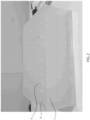
- FIG. 1 depicts a current needle design with a smooth exterior surface piercing a seal of a sample source, wherein portions of a seal material 8 are clinging to the needle. It has been determined that a high coefficient of friction on a smooth exterior of current needle designs for liquid chromatography applications causes certain plastic seals 8 of a sample source to cling to the smooth exterior surface of the needle, and stretch around the needle during piercing, as shown in FIG. 1 . The stretching and clinging of the seal material 8 can results in parts of the seal material 8 to break-off, resulting in unwanted plastic sleeves, pieces, objects, wads, etc.
- FIG. 2 depicts stretched, leftover seal material 9 on a sample source 7, such as a wellplate, caused by unwanted clinging of the seal material onto the current needle of FIG. 1 .
- Embodiments of needle 100 may be a needle, a sample needle, an injection needle, a textured needle, a liquid chromatography needle, an autosampler needle, an injector, a sample injector, and the like.
- Embodiments of the needle 100 may include a first end 1, a second end 2, and a needle body 50.
- Embodiments of the needle body 50 may be a body, a body portion, or other structural element that defines a general structure of the needle 100.
- the needle body 50 of the needle 100 may have an overall length, L.
- the overall length, L may vary depending on the application, a size of a sample compartment of an autosampler, a volume of sample to be analyzed, etc. In an exemplary embodiment, the overall length, L, may be between 3-4 inches (7.62cm-10.16cm).
- Embodiments of the needle 100 may be comprised of metal, metal alloy, metal alloys, or a combination thereof. In an exemplary embodiment, the needle 100 may be comprised of stainless steel or a chromium alloy, such as MP35N ® .
- the needle 100 includes a smooth surface region 10 and a textured surface region 20, and may include a non-textured region 30.
- the needle 100 is a needle for aspirating a sample from a sample source 7 and injecting the sample into a liquid chromatography system, wherein the needle 100 includes a needle body 50 having a rough textured surface finish 25 applied to the textured region 20, which is offset from a tip of the needle body 50 by the smooth surface region 10, wherein the rough textured surface finish 25 reduces a coefficient of friction of the needle body 50.
- a friction between the needle body 50 and the seal 8 can be reduced to prevent, hinder, or otherwise reduce a likelihood of a stretching of the seal 8 (e.g. plastic seal material over a wellplate) as the needle 100 pierces the seal 8 to aspirate the sample from within the sample source 7.
- the seal 8 e.g. plastic seal material over a wellplate
- embodiments of the needle 100 include a smooth surface region 10.
- Embodiments of the smooth surface region 10 may be a region, portion, section, etc. of an exterior surface of the needle body 50 having a smooth surface, or smooth surface finish 15.
- the smooth surface finish 15 may have a max surface roughness Ra of 16 ⁇ inch (0.4064 ⁇ m).
- the smooth surface region 10 is proximate a tip 11 of the needle body 50.
- the smooth surface region 10 may encompass the tip 11 of the needle body 50.
- the tip 11 of the needle body 50 may be a tip, a nose, an aspirating end of the needle body 50, and the like, which may be configured to initially engage and pierce a cover seal 8 of a sample source 7.
- the smooth surface region 10 of the needle body 50 extends from the first end 1 of the needle 100, or from a tip 11 of the needle body 50 a distance, prior to reaching the textured surface region 20.
- the smooth surface region 10 may extend at least 0.01 inches (0.0254cm) from the first end 1 of the needle 100.
- the smooth surface region 10 may extend 0.025 inches ⁇ 0.15 inches (0.065cm ⁇ 0.381cm) from the first end 1 of the needle 100.
- the smooth surface region 10 may extend from the first end 1 of the needle 100 less than 0.01 inches (0,0254cm).
- Embodiments of the needle 100 include the smooth surface region 10 so that smooth surface finish 15 of the tip 11 maintains a liquid tight seal between the tip 11 of the needle body 50 and an injection seat when the needle injects the sample into an analytic flow path of the liquid chromatography system. Preserving a smooth surface finish 15 on the tip 11 of the needle body 50 can maintain a proper sealing when the needle 100 inserts the sample in to the analytic flow path. For example, after the needle 100 aspirates the sample, the needle 100 moves to an inject station where the needle 100 is loaded against an inject seat creating a liquid-tight seal during injection. A smooth surface finish 15 on the needle tip 11 may ensure that a liquid tight seal forms between the needle tip 11 and the inject seat during injection.
- embodiments of the needle body 50 include a textured surface region 20.
- Embodiments of the textured surface region 20 may be a textured region, a rough surface texture region, a region of reduced coefficient of friction, an enhanced surface roughness region, a region of increased roughness, and the like.
- the textured surface region 20 may reside next to or contiguous with the smooth surface region 10 along the exterior surface of the needle 100. Further, the textured surface region 20 may be offset a distance from the tip 11 of the needle body 50.
- a smooth surface finish 15 is preserved at the tip, while a total surface area of smooth surface finish of the needle 100 that causes problems with clinging of the seal material of the sample source 8 as described above, is limited.
- an exterior surface of the needle 100 includes a rough surface texture finish 25.
- Embodiments of the rough surface texture finish 25 may have a roughness Ra greater than 15 ⁇ inch (0.3810 ⁇ m).
- the rough surface texture finish 25 may have a roughness Ra between 15 ⁇ inch (0.3810 ⁇ m) and 30 ⁇ inch (0.7620 ⁇ m).
- Embodiments of the rough surface texture finish 25 may have a roughness Ra greater than 30 ⁇ inch (0.7620 ⁇ m), but a surface roughness Ra of the textured surface finish 25 may be limited because a surface that has been overly roughened will increase the coefficient of friction and the seal material may still cling and stretch.
- the textured surface finish 25 may have a max Ra of 80 ⁇ inch (2.032 ⁇ m).
- a coefficient of friction is reduced so that the plastic seal material 8 does not stretch or sleeve during piercing of the seal 8 of the sample source 7.
- the addition of a textured surface finish 25 to the exterior of the needle body 50 may improve on current needle designs by improving piercing performance and decreasing a number of failures due to stretching or sleeving of plastic seals (e.g. wellplate seal).
- the textured surface finish 25 may be created using a bead blast technique.
- the exterior surface of the needle body 50 may be bead blasted by spraying glass beads at a specific pressure to form the surface texture finish 25.
- measurements may be taken to ensure that the roughness Ra falls within a certain range (e.g. 15 ⁇ inch - 30 ⁇ inch / 0.381 ⁇ m - 0.762 ⁇ m).
- the textured surface finish 25 may be created using shot peening methods.
- the surface texture may be formed using shot peening processes involving bombarding the needle body 50 with a stream of stainless steel balls being at a specific pressure to form the surface texture finish 25.
- the textured surface may be formed using a laser etching process.
- the textured surface may be formed by a grinding technique.
- Other surface texturing and/or roughening methods may be used to accomplish a surface roughness Ra of the needle 100 described herein.
- embodiments of the needle body 50 may also include a non-textured region 30.
- Embodiments of the non-textured region 30 may potentially comprise a region, section, portion, etc. of the needle body 50 residing next to or contiguous with the textured surface region 20 between the textured surface region 20 and the second end 2 of the needle 100.
- the non-textured region 30 may have a same roughness Ra as the smooth surface region 10 proximate the tip, or a different roughness Ra than both the smooth surface region 10 and the textured region 20.
- the needle 100 may not have a non-textured region 30, wherein the needle body 50 comprised the rough surface texture finish 25 from an edge of the smooth surface region 10 to the second end 2 of the needle 100.
- an entire needle body 50 may be comprised of the textured region 20.
- the needle body 50 may not include a smooth surface finish proximate the needle tip 11, and may instead be textured as in the textured region 20.
- the textured region 20 may extend from a point between the first end 1 and the second end 2 of the needle body 50 to the tip 11 of the needle body 50.
- the needle body 50 may thus in this arrangement be textured starting at a tip 11 of the needle body 50 and continuing for a certain length from the tip 11, and even up to the second end 2 of the needle body 50.
- FIG. 5 depicts a detailed view of Detail B of FIG. 3 , in accordance with embodiments of the present invention.
- the detailed view of FIG. 5 depicts the tip 11 of the needle body 50, the smooth surface region 10 and a portion of the textured surface region 20.
- Embodiments of the tip 11 may have a diameter, referred to as a nose diameter ND.
- the ND may be a diameter of the needle body 50 at the tip 11. In an exemplary embodiment, the ND may be about 0.014 inches (0.03556cm).
- a diameter D of the needle body 50 may be a max diameter of the needle body 50. The max diameter D of the needle body 50 may vary.
- the max needle diameter D may be about 0.04inches (0.1016cm).
- embodiments of the needle 100 may include an inner fluidic pathway 12.
- Embodiments of the inner fluidic pathway 12 may be an inner bore extending generally axially through the needle 100.
- the sample from the sample source 7 may flow through the fluidic pathway 12.
- Embodiments of the fluidic pathway 12 may have a bore diameter BD that may vary depending on a volume of sample to be tested.
- the BD of the fluidic pathway 12 of the needle 100 may be about 0.005 inches (0.0127cm). In other embodiments, the BD may be about 0.010 inches (0.0254cm).
- the max diameter of the inner bore is 0.01 inches (0.0254cm).
- embodiments of the needle body 50 include a conical section CS.
- Embodiments of a conical section CS may be a portion of the needle body 50 that tapers towards the needle tip 11.
- a majority of the needle body 50 may have a uniform max diameter D, but the conical section CS may have a gradually reducing max diameter moving towards the tip 11 of the needle body 50.
- a length of the conical section CS of the needle body 50 may vary. In an exemplary embodiment, the length of the CS may be about 0.10 inches (0.0254cm).
- An angle, ⁇ , of the CS of the needle body 50 may be less than 15°. However, the angle, ⁇ , may vary and be greater than 15°.
- FIG. 6 depicts a detailed view of Detail C of FIG. 3 , in accordance with embodiments of the present invention.
- the detailed view of FIG. 6 depicts the second end 2 of the needle body 50.
- Embodiments of the needle body 50 may include a component attachment region 70.
- Embodiments of the component attachment region 70 may be configured to receive a component, fastener, element, part, etc. of a liquid chromatography system.
- FIG. 7 depicts a textured needle 100 attached to a tubing 95 of a liquid chromatography system, in accordance with embodiments of the present invention.
- the needle 100 may be operably connected to a tubing 95 of a liquid chromatography system.
- a ferrule 90 may surround portions of the tubing 95 and the needle 100.
- FIG. 8 depicts an enlarged view of FIG. 7 , showing the tubing 95 connected to the textured needle 100, in accordance with embodiments of the present invention.
- the needle 100 may be welded to the tubing 95.
- the needle 100 may be laser welded to the tubing 95.
- FIG. 9 depicts a detailed view of Detail J of FIG. 8 , in accordance with embodiments of the present invention.
- the component attachment region 70 of the needle body 50 may receive an end of tubing 95, which may be laser welded (welding spots shown schematically as 93).
- embodiments of the needle 100 may be operably connected to a tubing 95 of a liquid chromatograph system.
- FIG. 10 depicts a schematic fluidic diagram of an autosampler 200 of a liquid chromatography system, having a needle 100 of FIG. 3 , in accordance with embodiments of the present invention.
- the needle 100 may be used to aspirate sample 5 from a sample source 7 for injection into an analytic flow path and eventually to a column for chromatographic analysis.
- the position shown in FIG. 10 is an aspirate position of the needle 100, which has pierced a seal 8 of the sample source 7, such as a well plate, for aspirating the sample 5.
- Embodiments of the autosampler 200 e.g.
- sample manager may include a sample compartment 80 and an injection valve 81, as well as other features and components of an autosampler for liquid chromatography applications.
- Embodiments of the injection valve 81 may be inject the sample 5 into an analytic flow path of the liquid chromatography system to a column for chromatographic analysis.
- Embodiments of the sample compartment 80 may be configured to receive at least one sample source 7 having a seal 8.
- the sample compartment 80 may house, receive, or otherwise cooperate with an array of wellplates containing sample 5.
- Components of autosampler 200 such as a process sample manager, may automatically programmatically obtain sample 5 from the sample sources 7, for ultimately injecting into the column via the injection valve 81.
- the needle 100 may be a part of the sample compartment 80 for cooperating with the sample source containers 7.
- the needle 100 may be housed within the sample compartment 80 of the autosampler 200 for liquid chromatography processes.
- the needle 100 may be fluidically connected to the injection valve 81, wherein the needle 100 may be configured to aspirate the sample 5 from the at least one sample source 7 by piercing the seal 8 of the at least one sample source 7, and then inject the sample 5 into the analytic flow path of a liquid chromatography system.
- FIG. 11 depicts a schematic diagram of a liquid chromatography system 300, in accordance with embodiments of the present invention.
- Embodiments of a liquid chromatography system 300 may include a mobile phase, such as a solvent reservoir/source, one or more pumps, the autosampler 200 in fluid communication with the sample, a column, and a detector, , as known to those skilled in the art of liquid chromatography.
- a method of improving a piercing performance of a needle 100 in a liquid chromatography system 200 may include reducing a coefficient of friction of the needle 100 by forming a rough textured surface region 20 on an exterior surface of the needle 100, such that when the needle pierces a seal 8 of a sample source 7, the seal 8 does not cling to the rough textured surface region 20 of the needle 100 as a result of the reduced coefficient of friction.
Landscapes
- Engineering & Computer Science (AREA)
- Physics & Mathematics (AREA)
- Mechanical Engineering (AREA)
- Optics & Photonics (AREA)
- Chemical & Material Sciences (AREA)
- Analytical Chemistry (AREA)
- Plasma & Fusion (AREA)
- Health & Medical Sciences (AREA)
- General Physics & Mathematics (AREA)
- Immunology (AREA)
- Pathology (AREA)
- General Health & Medical Sciences (AREA)
- Biochemistry (AREA)
- Life Sciences & Earth Sciences (AREA)
- Chemical Kinetics & Catalysis (AREA)
- Sampling And Sample Adjustment (AREA)
Claims (13)
- Nadel (100) zum Ansaugen einer Probe von einer Probenquelle und zum Injizieren der Probe in ein Flüssigkeitschromatographiesystem, wobei die Nadel umfasst:einen Nadelkörper (50) einschließend eine Spitze (11) und einen konischen Abschnitt (CS) angrenzend an die Spitze, wobei der konische Abschnitt in einem Bereich (20), der von der Spitze versetzt ist, eine raue texturierte Oberflächenbeschaffenheit (25) aufweist, wobei der Nadelkörper ferner eine glatte Oberflächenausführung (15) in einem Bereich (10) aufweist, der sich von der Spitze zu dem rauen texturierten Oberflächenbereich (20) erstreckt;wobei die raue texturierte Oberflächenausführung (25) einen Reibungskoeffizienten des Nadelkörpers reduziert, um zu verhindern, dass ein Dichtungsmaterial, das die Probenquelle bedeckt, an dem Nadelkörper haftet, wenn die Nadel in die Probenquelle eintritt oder aus ihr austritt;wobei die glatte Oberflächenausführung (15) eine flüssigkeitsdichte Abdichtung zwischen der Spitze des Nadelkörpers und einem Injektionssitz aufrechterhält, wenn die Nadel die Probe in einen analytischen Strömungsweg des Flüssigkeitschromatographiesystems injiziert.
- Nadel nach Anspruch 1, wobei die raue texturierte Oberflächenausführung eine Oberflächenrauheit Ra größer als 0,3810 µm aufweist.
- Nadel nach Anspruch 1, wobei der Nadelkörper aus Metall oder einer Metalllegierung besteht.
- Nadel nach Anspruch 1, wobei die raue texturierte Oberflächenausführung von der Spitze des Nadelkörpers um mindestens 0,0254 cm versetzt ist.
- Nadel nach Anspruch 1, wobei die raue texturierte Oberflächenausführung durch Kugelstrahlen des Nadelkörpers gebildet wird.
- Nadel nach Anspruch 1, ferner umfassend: eine Innenbohrung, die einen Flüssigkeitsweg (12) der Probe durch den Nadelkörper bereitstellt, und ein gegenüberliegendes Befestigungsende zum Befestigen an einer Komponente eines Autosamplers des Flüssigkeitschromatographiesystems.
- Nadel nach Anspruch 6, wobei die Innenbohrung einen maximalen Durchmesser von 0,0254 cm aufweist.
- Nadel nach Anspruch 1, wobei eine Rauheit Ra der rauen texturierten Oberflächenausführung zwischen 0,3810 µm und 0,7620 µm liegt.
- Nadel nach Anspruch 1, wobei sich die raue texturierte Oberflächenausführung mindestens 5,08 cm von der glatten Oberflächenausführung der Spitze des Nadelkörpers entlang einer Außenoberfläche des Nadelkörpers erstreckt.
- Nadel nach Anspruch 1, wobei die glatte Oberflächenausführung einen höheren Reibungskoeffizienten aufweist als die raue texturierte Oberflächenausführung.
- Autosampler (200) eines Flüssigkeitschromatographiesystems, umfassend:ein Injektionsventil (81) zum Injizieren einer Probe (5) in einen analytischen Strömungsweg des Flüssigkeitschromatographiesystems;ein Probenfach (80), wobei das Probenfach so konfiguriert ist, dass es mindestens eine Probenquelle (7) mit einer Dichtung aufnimmt; undeine Nadel (100) nach Anspruch 1.
- Verfahren zum Herstellen einer Nadel (100) nach Anspruch 1, wobei das Verfahren umfasst:
Reduzieren eines Reibungskoeffizienten der Nadel durch Bilden einer raue texturierten Oberflächenausführung (20) auf einer Außenoberfläche eines konischen Abschnitts (CS) der Nadel. - Verfahren nach Anspruch 12, wobei der raue texturierte Oberflächenbereich eine Rauheit Ra von zwischen 0,3810 µm und 0,7620 µm aufweist.
Applications Claiming Priority (2)
| Application Number | Priority Date | Filing Date | Title |
|---|---|---|---|
| US201862639305P | 2018-03-06 | 2018-03-06 | |
| PCT/US2019/020699 WO2019173300A1 (en) | 2018-03-06 | 2019-03-05 | Textured needle for improved piercing performance in liquid chromatography applications |
Publications (2)
| Publication Number | Publication Date |
|---|---|
| EP3762147A1 EP3762147A1 (de) | 2021-01-13 |
| EP3762147B1 true EP3762147B1 (de) | 2024-12-25 |
Family
ID=65818631
Family Applications (1)
| Application Number | Title | Priority Date | Filing Date |
|---|---|---|---|
| EP19712362.3A Active EP3762147B1 (de) | 2018-03-06 | 2019-03-05 | Texturierte nadel für verbesserte durchstechungsleistung bei flüssigkeitschromatografieanwendungen |
Country Status (4)
| Country | Link |
|---|---|
| US (1) | US10859541B2 (de) |
| EP (1) | EP3762147B1 (de) |
| CN (1) | CN111819001A (de) |
| WO (1) | WO2019173300A1 (de) |
Family Cites Families (19)
| Publication number | Priority date | Publication date | Assignee | Title |
|---|---|---|---|---|
| JP3442153B2 (ja) * | 1994-08-23 | 2003-09-02 | マニー株式会社 | 縫合針の成形型及び縫合針 |
| JP3417263B2 (ja) * | 1997-08-29 | 2003-06-16 | マニー株式会社 | 縫合針 |
| US6214030B1 (en) * | 1998-08-10 | 2001-04-10 | Mani, Inc. | Suture needle |
| JP4155218B2 (ja) * | 2004-03-30 | 2008-09-24 | 株式会社島津製作所 | オートサンプラ |
| JP2005099056A (ja) * | 2004-12-28 | 2005-04-14 | Shimadzu Corp | オートサンプラ |
| GB2433122B (en) * | 2005-12-10 | 2008-07-23 | Endet Ltd | Gas sampling probe |
| JP2010107389A (ja) * | 2008-10-30 | 2010-05-13 | Shimadzu Corp | オートサンプラ |
| WO2011085285A1 (en) * | 2010-01-11 | 2011-07-14 | Waters Technologies Corporation | Injection port needle support and washing |
| JP5471846B2 (ja) * | 2010-05-31 | 2014-04-16 | 株式会社島津製作所 | 液体試料導入装置及び液体試料導入方法 |
| JP5843516B2 (ja) | 2010-08-25 | 2016-01-13 | アークレイ株式会社 | 分析装置および分析方法 |
| GB201117467D0 (en) * | 2011-10-11 | 2011-11-23 | Rolls Royce Plc | A method of providing through-thickness reinforcement of a laminated material |
| JP3180120U (ja) * | 2012-09-21 | 2012-12-06 | 株式会社島津製作所 | キャップピアッシング用穿孔針 |
| US10154924B2 (en) * | 2013-01-28 | 2018-12-18 | Novartis Ag | Schlemm's canal devices and method for improving fluid flow |
| CN103602396A (zh) * | 2013-11-18 | 2014-02-26 | 青岛广联达精密机械有限公司 | 一种新型切削液组合物 |
| CN204600539U (zh) | 2015-04-10 | 2015-09-02 | 山东大学 | 一种新型减阻表面纹理活检针 |
| TWI554391B (zh) * | 2015-05-15 | 2016-10-21 | 國立臺灣科技大學 | 金屬玻璃薄膜 |
| CN105033461B (zh) * | 2015-06-24 | 2017-03-22 | 江苏大学 | 一种利用激光获得减摩耐磨工件表面的方法 |
| US10545073B2 (en) * | 2016-03-02 | 2020-01-28 | Jp Scientific Limited | Method and instrument for extracting a component from a sample |
| CN206239830U (zh) * | 2016-06-20 | 2017-06-13 | 吕霄玲 | 注射器 |
-
2019
- 2019-03-05 WO PCT/US2019/020699 patent/WO2019173300A1/en not_active Ceased
- 2019-03-05 CN CN201980017499.8A patent/CN111819001A/zh active Pending
- 2019-03-05 US US16/292,857 patent/US10859541B2/en active Active
- 2019-03-05 EP EP19712362.3A patent/EP3762147B1/de active Active
Also Published As
| Publication number | Publication date |
|---|---|
| CN111819001A (zh) | 2020-10-23 |
| US20190277812A1 (en) | 2019-09-12 |
| EP3762147A1 (de) | 2021-01-13 |
| US10859541B2 (en) | 2020-12-08 |
| WO2019173300A1 (en) | 2019-09-12 |
Similar Documents
| Publication | Publication Date | Title |
|---|---|---|
| JP2984376B2 (ja) | ダストワイパー付き注入隔壁 | |
| US4954149A (en) | Injection septum | |
| US8388268B2 (en) | Cutting assembly | |
| US20140064996A1 (en) | Plunger pump | |
| EP2668988B1 (de) | Kanalblasenreduzierungsvorrichtung, Kanalblasenreduzierungsprogramm, Kanalblasenreduzierungsverfahren, Flüssigkeitsbereitstellungsvorrichtung und Chromatographievorrichtung | |
| US9322750B2 (en) | Needle trap for use with a gas chromatograph-mass spectrometer for field sampling and analysis | |
| JP6375690B2 (ja) | シリンジニードル一体型固相抽出装置及びそれを用いた試料前処理方法 | |
| JPS6318137B2 (de) | ||
| GB0129656D0 (en) | Beverage brewing methods and apparatus | |
| US20130019699A1 (en) | Injection port needle support and washing | |
| US20160252435A1 (en) | Solid phase extraction cartridge | |
| JP6908125B2 (ja) | 超臨界流体クロマトグラフ、及び超臨界流体クロマトグラフィー分析方法 | |
| US5114033A (en) | Apparatus for discharging contents of a sealed container | |
| US10859541B2 (en) | Textured needle for improved piercing performance in liquid chromatography applications | |
| US20070095158A1 (en) | Automatic sampler | |
| JP5181257B2 (ja) | 自動分析装置において使用可能なサンプリング装置及びサンプリング方法 | |
| US10502332B2 (en) | Duckbill valve assemblies and apparatus and methods including same | |
| DE2004181A1 (de) | Vorsaeulen-Einlass fuer Chromatographen | |
| WO2010037827A2 (de) | Tiefsttemperaturbehälter | |
| US3783694A (en) | Punch for piercing sample capsules | |
| EP3775871B1 (de) | Dichtungspackung für automatischen probenehmer zur verminderung von verschleppung | |
| Fiselier et al. | Injector‐internal thermal desorption from edible oils. Part 2: Chromatographic optimization for the analysis of migrants from food packaging material | |
| US20190187110A1 (en) | Chambered septum | |
| DE102011075146A1 (de) | Kapillarende als sitz für einen probeninjektor | |
| JP2008164498A (ja) | 試料注入装置及び液体クロマトグラフィー装置 |
Legal Events
| Date | Code | Title | Description |
|---|---|---|---|
| STAA | Information on the status of an ep patent application or granted ep patent |
Free format text: STATUS: UNKNOWN |
|
| STAA | Information on the status of an ep patent application or granted ep patent |
Free format text: STATUS: THE INTERNATIONAL PUBLICATION HAS BEEN MADE |
|
| PUAI | Public reference made under article 153(3) epc to a published international application that has entered the european phase |
Free format text: ORIGINAL CODE: 0009012 |
|
| STAA | Information on the status of an ep patent application or granted ep patent |
Free format text: STATUS: REQUEST FOR EXAMINATION WAS MADE |
|
| 17P | Request for examination filed |
Effective date: 20200701 |
|
| AK | Designated contracting states |
Kind code of ref document: A1 Designated state(s): AL AT BE BG CH CY CZ DE DK EE ES FI FR GB GR HR HU IE IS IT LI LT LU LV MC MK MT NL NO PL PT RO RS SE SI SK SM TR |
|
| AX | Request for extension of the european patent |
Extension state: BA ME |
|
| RIN1 | Information on inventor provided before grant (corrected) |
Inventor name: AUCLAIR, JOHN M. Inventor name: KELLEY, SCOTT Inventor name: SOLOW, ROSE Inventor name: OSSWALD, PETER |
|
| DAV | Request for validation of the european patent (deleted) | ||
| DAX | Request for extension of the european patent (deleted) | ||
| STAA | Information on the status of an ep patent application or granted ep patent |
Free format text: STATUS: EXAMINATION IS IN PROGRESS |
|
| 17Q | First examination report despatched |
Effective date: 20221117 |
|
| REG | Reference to a national code |
Ref country code: DE Ref legal event code: R079 Ref document number: 602019063914 Country of ref document: DE Free format text: PREVIOUS MAIN CLASS: B01L0003020000 Ipc: G01N0030180000 |
|
| GRAP | Despatch of communication of intention to grant a patent |
Free format text: ORIGINAL CODE: EPIDOSNIGR1 |
|
| STAA | Information on the status of an ep patent application or granted ep patent |
Free format text: STATUS: GRANT OF PATENT IS INTENDED |
|
| RIC1 | Information provided on ipc code assigned before grant |
Ipc: B23K 26/282 20140101ALI20240702BHEP Ipc: B23K 26/352 20140101ALI20240702BHEP Ipc: G01N 30/24 20060101ALI20240702BHEP Ipc: G01N 30/18 20060101AFI20240702BHEP |
|
| INTG | Intention to grant announced |
Effective date: 20240717 |
|
| GRAS | Grant fee paid |
Free format text: ORIGINAL CODE: EPIDOSNIGR3 |
|
| GRAA | (expected) grant |
Free format text: ORIGINAL CODE: 0009210 |
|
| STAA | Information on the status of an ep patent application or granted ep patent |
Free format text: STATUS: THE PATENT HAS BEEN GRANTED |
|
| AK | Designated contracting states |
Kind code of ref document: B1 Designated state(s): AL AT BE BG CH CY CZ DE DK EE ES FI FR GB GR HR HU IE IS IT LI LT LU LV MC MK MT NL NO PL PT RO RS SE SI SK SM TR |
|
| REG | Reference to a national code |
Ref country code: GB Ref legal event code: FG4D |
|
| REG | Reference to a national code |
Ref country code: CH Ref legal event code: EP |
|
| REG | Reference to a national code |
Ref country code: DE Ref legal event code: R096 Ref document number: 602019063914 Country of ref document: DE |
|
| P01 | Opt-out of the competence of the unified patent court (upc) registered |
Free format text: CASE NUMBER: APP_64532/2024 Effective date: 20241205 |
|
| REG | Reference to a national code |
Ref country code: IE Ref legal event code: FG4D |
|
| REG | Reference to a national code |
Ref country code: LT Ref legal event code: MG9D |
|
| PG25 | Lapsed in a contracting state [announced via postgrant information from national office to epo] |
Ref country code: FI Free format text: LAPSE BECAUSE OF FAILURE TO SUBMIT A TRANSLATION OF THE DESCRIPTION OR TO PAY THE FEE WITHIN THE PRESCRIBED TIME-LIMIT Effective date: 20241225 |
|
| PG25 | Lapsed in a contracting state [announced via postgrant information from national office to epo] |
Ref country code: BG Free format text: LAPSE BECAUSE OF FAILURE TO SUBMIT A TRANSLATION OF THE DESCRIPTION OR TO PAY THE FEE WITHIN THE PRESCRIBED TIME-LIMIT Effective date: 20241225 |
|
| PG25 | Lapsed in a contracting state [announced via postgrant information from national office to epo] |
Ref country code: NO Free format text: LAPSE BECAUSE OF FAILURE TO SUBMIT A TRANSLATION OF THE DESCRIPTION OR TO PAY THE FEE WITHIN THE PRESCRIBED TIME-LIMIT Effective date: 20250325 |
|
| PG25 | Lapsed in a contracting state [announced via postgrant information from national office to epo] |
Ref country code: GR Free format text: LAPSE BECAUSE OF FAILURE TO SUBMIT A TRANSLATION OF THE DESCRIPTION OR TO PAY THE FEE WITHIN THE PRESCRIBED TIME-LIMIT Effective date: 20250326 Ref country code: LV Free format text: LAPSE BECAUSE OF FAILURE TO SUBMIT A TRANSLATION OF THE DESCRIPTION OR TO PAY THE FEE WITHIN THE PRESCRIBED TIME-LIMIT Effective date: 20241225 |
|
| PG25 | Lapsed in a contracting state [announced via postgrant information from national office to epo] |
Ref country code: RS Free format text: LAPSE BECAUSE OF FAILURE TO SUBMIT A TRANSLATION OF THE DESCRIPTION OR TO PAY THE FEE WITHIN THE PRESCRIBED TIME-LIMIT Effective date: 20250325 |
|
| REG | Reference to a national code |
Ref country code: NL Ref legal event code: MP Effective date: 20241225 |
|
| PG25 | Lapsed in a contracting state [announced via postgrant information from national office to epo] |
Ref country code: NL Free format text: LAPSE BECAUSE OF FAILURE TO SUBMIT A TRANSLATION OF THE DESCRIPTION OR TO PAY THE FEE WITHIN THE PRESCRIBED TIME-LIMIT Effective date: 20241225 |
|
| REG | Reference to a national code |
Ref country code: AT Ref legal event code: MK05 Ref document number: 1754567 Country of ref document: AT Kind code of ref document: T Effective date: 20241225 |
|
| PG25 | Lapsed in a contracting state [announced via postgrant information from national office to epo] |
Ref country code: SM Free format text: LAPSE BECAUSE OF FAILURE TO SUBMIT A TRANSLATION OF THE DESCRIPTION OR TO PAY THE FEE WITHIN THE PRESCRIBED TIME-LIMIT Effective date: 20241225 |
|
| PG25 | Lapsed in a contracting state [announced via postgrant information from national office to epo] |
Ref country code: PL Free format text: LAPSE BECAUSE OF FAILURE TO SUBMIT A TRANSLATION OF THE DESCRIPTION OR TO PAY THE FEE WITHIN THE PRESCRIBED TIME-LIMIT Effective date: 20241225 |
|
| PG25 | Lapsed in a contracting state [announced via postgrant information from national office to epo] |
Ref country code: ES Free format text: LAPSE BECAUSE OF FAILURE TO SUBMIT A TRANSLATION OF THE DESCRIPTION OR TO PAY THE FEE WITHIN THE PRESCRIBED TIME-LIMIT Effective date: 20241225 |
|
| PG25 | Lapsed in a contracting state [announced via postgrant information from national office to epo] |
Ref country code: IS Free format text: LAPSE BECAUSE OF FAILURE TO SUBMIT A TRANSLATION OF THE DESCRIPTION OR TO PAY THE FEE WITHIN THE PRESCRIBED TIME-LIMIT Effective date: 20250425 |
|
| PG25 | Lapsed in a contracting state [announced via postgrant information from national office to epo] |
Ref country code: PT Free format text: LAPSE BECAUSE OF FAILURE TO SUBMIT A TRANSLATION OF THE DESCRIPTION OR TO PAY THE FEE WITHIN THE PRESCRIBED TIME-LIMIT Effective date: 20250428 |
|
| PG25 | Lapsed in a contracting state [announced via postgrant information from national office to epo] |
Ref country code: EE Free format text: LAPSE BECAUSE OF FAILURE TO SUBMIT A TRANSLATION OF THE DESCRIPTION OR TO PAY THE FEE WITHIN THE PRESCRIBED TIME-LIMIT Effective date: 20241225 |
|
| PG25 | Lapsed in a contracting state [announced via postgrant information from national office to epo] |
Ref country code: RO Free format text: LAPSE BECAUSE OF FAILURE TO SUBMIT A TRANSLATION OF THE DESCRIPTION OR TO PAY THE FEE WITHIN THE PRESCRIBED TIME-LIMIT Effective date: 20241225 Ref country code: AT Free format text: LAPSE BECAUSE OF FAILURE TO SUBMIT A TRANSLATION OF THE DESCRIPTION OR TO PAY THE FEE WITHIN THE PRESCRIBED TIME-LIMIT Effective date: 20241225 |
|
| PG25 | Lapsed in a contracting state [announced via postgrant information from national office to epo] |
Ref country code: SK Free format text: LAPSE BECAUSE OF FAILURE TO SUBMIT A TRANSLATION OF THE DESCRIPTION OR TO PAY THE FEE WITHIN THE PRESCRIBED TIME-LIMIT Effective date: 20241225 |
|
| PG25 | Lapsed in a contracting state [announced via postgrant information from national office to epo] |
Ref country code: CZ Free format text: LAPSE BECAUSE OF FAILURE TO SUBMIT A TRANSLATION OF THE DESCRIPTION OR TO PAY THE FEE WITHIN THE PRESCRIBED TIME-LIMIT Effective date: 20241225 |
|
| PG25 | Lapsed in a contracting state [announced via postgrant information from national office to epo] |
Ref country code: IT Free format text: LAPSE BECAUSE OF FAILURE TO SUBMIT A TRANSLATION OF THE DESCRIPTION OR TO PAY THE FEE WITHIN THE PRESCRIBED TIME-LIMIT Effective date: 20241225 |
|
| PG25 | Lapsed in a contracting state [announced via postgrant information from national office to epo] |
Ref country code: SE Free format text: LAPSE BECAUSE OF FAILURE TO SUBMIT A TRANSLATION OF THE DESCRIPTION OR TO PAY THE FEE WITHIN THE PRESCRIBED TIME-LIMIT Effective date: 20241225 |
|
| REG | Reference to a national code |
Ref country code: DE Ref legal event code: R097 Ref document number: 602019063914 Country of ref document: DE |
|
| PG25 | Lapsed in a contracting state [announced via postgrant information from national office to epo] |
Ref country code: DK Free format text: LAPSE BECAUSE OF FAILURE TO SUBMIT A TRANSLATION OF THE DESCRIPTION OR TO PAY THE FEE WITHIN THE PRESCRIBED TIME-LIMIT Effective date: 20241225 |
|
| PG25 | Lapsed in a contracting state [announced via postgrant information from national office to epo] |
Ref country code: MC Free format text: LAPSE BECAUSE OF FAILURE TO SUBMIT A TRANSLATION OF THE DESCRIPTION OR TO PAY THE FEE WITHIN THE PRESCRIBED TIME-LIMIT Effective date: 20241225 |
|
| REG | Reference to a national code |
Ref country code: CH Ref legal event code: H13 Free format text: ST27 STATUS EVENT CODE: U-0-0-H10-H13 (AS PROVIDED BY THE NATIONAL OFFICE) Effective date: 20251024 |
|
| PLBE | No opposition filed within time limit |
Free format text: ORIGINAL CODE: 0009261 |
|
| STAA | Information on the status of an ep patent application or granted ep patent |
Free format text: STATUS: NO OPPOSITION FILED WITHIN TIME LIMIT |
|
| PG25 | Lapsed in a contracting state [announced via postgrant information from national office to epo] |
Ref country code: LU Free format text: LAPSE BECAUSE OF NON-PAYMENT OF DUE FEES Effective date: 20250305 |
|
| 26N | No opposition filed |
Effective date: 20250926 |
|
| REG | Reference to a national code |
Ref country code: BE Ref legal event code: MM Effective date: 20250331 |
|
| PG25 | Lapsed in a contracting state [announced via postgrant information from national office to epo] |
Ref country code: FR Free format text: LAPSE BECAUSE OF NON-PAYMENT OF DUE FEES Effective date: 20250331 |
|
| PG25 | Lapsed in a contracting state [announced via postgrant information from national office to epo] |
Ref country code: BE Free format text: LAPSE BECAUSE OF NON-PAYMENT OF DUE FEES Effective date: 20250331 |
|
| PG25 | Lapsed in a contracting state [announced via postgrant information from national office to epo] |
Ref country code: CH Free format text: LAPSE BECAUSE OF NON-PAYMENT OF DUE FEES Effective date: 20250331 |
|
| PG25 | Lapsed in a contracting state [announced via postgrant information from national office to epo] |
Ref country code: IE Free format text: LAPSE BECAUSE OF NON-PAYMENT OF DUE FEES Effective date: 20250305 |
|
| PGFP | Annual fee paid to national office [announced via postgrant information from national office to epo] |
Ref country code: GB Payment date: 20260220 Year of fee payment: 8 |
|
| PGFP | Annual fee paid to national office [announced via postgrant information from national office to epo] |
Ref country code: DE Payment date: 20260219 Year of fee payment: 8 |
|
| PG25 | Lapsed in a contracting state [announced via postgrant information from national office to epo] |
Ref country code: HR Free format text: LAPSE BECAUSE OF FAILURE TO SUBMIT A TRANSLATION OF THE DESCRIPTION OR TO PAY THE FEE WITHIN THE PRESCRIBED TIME-LIMIT Effective date: 20241225 |