EP3760954A1 - Dispositif formant appareil électroménager - Google Patents
Dispositif formant appareil électroménager Download PDFInfo
- Publication number
- EP3760954A1 EP3760954A1 EP20179995.4A EP20179995A EP3760954A1 EP 3760954 A1 EP3760954 A1 EP 3760954A1 EP 20179995 A EP20179995 A EP 20179995A EP 3760954 A1 EP3760954 A1 EP 3760954A1
- Authority
- EP
- European Patent Office
- Prior art keywords
- inner container
- household appliance
- latching
- latching element
- appliance device
- Prior art date
- Legal status (The legal status is an assumption and is not a legal conclusion. Google has not performed a legal analysis and makes no representation as to the accuracy of the status listed.)
- Ceased
Links
Images


Classifications
-
- F—MECHANICAL ENGINEERING; LIGHTING; HEATING; WEAPONS; BLASTING
- F25—REFRIGERATION OR COOLING; COMBINED HEATING AND REFRIGERATION SYSTEMS; HEAT PUMP SYSTEMS; MANUFACTURE OR STORAGE OF ICE; LIQUEFACTION SOLIDIFICATION OF GASES
- F25D—REFRIGERATORS; COLD ROOMS; ICE-BOXES; COOLING OR FREEZING APPARATUS NOT OTHERWISE PROVIDED FOR
- F25D23/00—General constructional features
- F25D23/06—Walls
- F25D23/062—Walls defining a cabinet
-
- F—MECHANICAL ENGINEERING; LIGHTING; HEATING; WEAPONS; BLASTING
- F25—REFRIGERATION OR COOLING; COMBINED HEATING AND REFRIGERATION SYSTEMS; HEAT PUMP SYSTEMS; MANUFACTURE OR STORAGE OF ICE; LIQUEFACTION SOLIDIFICATION OF GASES
- F25D—REFRIGERATORS; COLD ROOMS; ICE-BOXES; COOLING OR FREEZING APPARATUS NOT OTHERWISE PROVIDED FOR
- F25D21/00—Defrosting; Preventing frosting; Removing condensed or defrost water
- F25D21/04—Preventing the formation of frost or condensate
Definitions
- the invention relates to a household appliance device, in particular a household refrigerator device, according to the preamble of claim 1.
- the object of the invention is in particular to provide a generic device with improved properties with regard to assembly.
- the object is achieved according to the invention by the features of claim 1, while advantageous embodiments and developments of the invention can be found in the subclaims.
- the invention is based on a household appliance device, in particular a household refrigerator device, with at least one inner container, with at least one end strip and with a latching unit which connects the inner container to the end strip in an assembled state by means of a detent.
- the latching unit have at least one latching element which is located at least essentially in the center with respect to at least one lateral extension of the inner container.
- Such a configuration makes it possible to provide a generic device with improved properties with regard to assembly, in particular with regard to an assembly-compatible connection of the end strip to the inner container.
- an advantageously tunable and positionally accurate connection of the inner container to the end strip can be achieved.
- a high manufacturing accuracy can in particular be achieved by such a configuration.
- Such a configuration also enables a cost-effective connection solution for at least one inner container with at least one end strip.
- a “household appliance device”, in particular a “household refrigerator device”, should be understood to mean in particular at least one part, in particular a subassembly, of a household appliance, in particular a household refrigerator.
- the household appliance device, in particular the household refrigerator device can also include the entire household appliance, in particular the entire household refrigerator.
- a household appliance designed as a household refrigerator is provided to cool goods to be chilled, in particular food such as beverages, meat, fish, milk and / or dairy products, in the at least one operating state, in particular to ensure a longer shelf life of the goods to be cooled.
- the household appliance designed as a household refrigerator can in particular be a freezer and advantageously a refrigerator and / or freezer.
- a household appliance comprising the household appliance device could, for example, alternatively be designed as a household cleaning appliance, such as a washing machine and / or a dishwasher and / or a dryer, and / or as a household cooking appliance, such as an oven and / or a stove be.
- a household cleaning appliance such as a washing machine and / or a dishwasher and / or a dryer
- a household cooking appliance such as an oven and / or a stove be.
- an “inner container” is to be understood in particular as a unit which defines at least one usable space of the household appliance device and in particular of the household appliance, wherein the usable space can be designed in particular as a cooking space, a cleaning space or preferably as a cooling space. Accordingly, the inner container can in particular be designed as a cooking muffle or as an inner liner.
- the inner container has, in particular, several walls which at least partially delimit the usable space.
- the inner container has, in particular on one side, an opening through which the usable space of the inner container is accessible, the opening in particular defining a plane referred to as the “opening plane”.
- the usable space of the inner container is provided to receive at least one item, for example a cooking item and / or a cleaning item and / or preferably a cooling item.
- the inner container comprises at least one material and is advantageously produced from this material, in particular in a shaping process suitable for this material.
- the material could be a metal, for example.
- the inner container comprises in particular one Plastic, preferably a thermoplastic plastic, and is particularly advantageously formed from such.
- the inner container can be produced in a thermoforming process, preferably a deep-drawing process.
- the inner container is produced from a suitable plastic by another shaping process, for example by an injection molding process or another shaping process that appears sensible to a person skilled in the art.
- a "front strip” is to be understood in particular as a unit which, in an assembled state, is provided to at least partially cover a component, a specific area of a component and / or a specific area between several components, the front strip being available to an operator in an operating state in particular is facing.
- the end strip forms a cover for a partial area of the at least one inner container and / or an area surrounding the inner container.
- the end strip is preferably provided to cover and / or produce a transition from the inner container to at least one adjoining component, in particular at least one further inner container.
- the end strip comprises a material and is advantageously produced from this material, in particular in a shaping process suitable for this material.
- the material can in particular be a material from one of the material groups of metals, non-metals, plastics, composite materials and / or ceramic materials.
- the end strip is produced as a stamped and bent component, in particular as a stamped and bent sheet metal part, preferably from a metal, in particular from sheet steel.
- the household appliance device can have several end strips, in particular an upper and a lower end strip. In an embodiment with more than one inner container, at least one further central end strip arranged between the inner containers can be provided.
- the household appliance device has at least one first laterally arranged end strip, the household appliance device in this case preferably additionally having a second laterally arranged end strip, which is arranged in particular opposite the first laterally arranged end strip on the opposite side.
- the end strip can in particular also have at least one of the following functions cover additionally: Backing parts can be attached to the front strip, to which, for example, door hinges and / or side walls of the household appliance device can be fixed. Together with side walls of the inner container, the end strip can form an upper and / or lower edge of the household appliance.
- the end strip can serve as a receptacle and in particular form a carrier part for different electronic components of the household appliance device and in particular the household appliance, such as, for example, operating electronics, a sensor and / or a switch.
- the end strip can also form, together with side walls of the inner container on the front side of a household appliance device, a metallic support surface for a magnetic door seal of the household appliance device and in particular of the household appliance.
- a “latching unit” is to be understood as meaning, in particular, a unit with at least one latching element which experiences an elastic deflection during a fastening process in order to subsequently latch into and / or behind a cooperating counter-latching element of the latching unit by an internal tensioning force.
- the latching unit can have several latching elements, preferably at least one second latching element, particularly preferably at least one third latching element.
- a “latching element” is to be understood as meaning, in particular, a specially shaped elastic element which experiences a particularly macroscopic and elastic deflection during a fastening process and, due to its geometry, is intended to engage in a further specially shaped part of a counter-latching element, for example a groove, and a enter into force-fit and / or preferably form-fit connection.
- the latching element can in particular be formed by an accumulation of material, the geometry of the latching element being in particular such that the portion of the latching unit which forms the latching element has a neck that enlarges the cross-section.
- the latching element is formed by material deformation, the latching element having a constant material thickness in a cross section.
- the latching element is formed by a material deformation and at the same time has a cross-section-enlarging attachment.
- An “elastic element” is to be understood in particular as an element which exhibits a targeted deformation under a load and, after a relief, through an elastic return returns to its original shape.
- a “latching” is to be understood in particular as a latching connection which connects at least a first component of the household appliance device to at least one further component of the household appliance device.
- the detent is in particular a force-fit and / or preferably form-fit connection.
- an "assembled state” is to be understood in particular as a state in which at least one component of the household appliance device, specifically the front strip, is connected to at least one further component of the household appliance device, specifically the inner container.
- a “lateral extension” is to be understood in particular as a direction which is parallel to an edge of the inner container which lies in the opening plane of the inner container.
- the lateral extension is advantageously oriented at least essentially parallel to a width direction of the inner container, in particular of the household appliance.
- the lateral extension can also be oriented at least essentially parallel to a height direction of the inner container, in particular of the household appliance. In an installation position of the household appliance device and in particular of the household appliance, the width direction of the inner container is oriented horizontally and the height direction of the inner container is oriented vertically.
- At least substantially parallel is to be understood as meaning, in particular, an alignment of a direction relative to a reference direction, in particular in a plane, the direction having a deviation from the reference direction, in particular less than 8 °, advantageously less than 5 ° and particularly advantageously less than 2 °.
- At least essentially in the middle is to be understood in particular that a deviation from a center point of the inner container with respect to the lateral extension is less than 10%, preferably less than 5% and particularly preferably less than 2% of the extension length of the inner container along the lateral extension.
- “Provided” is to be understood in particular as specifically designed and / or equipped. The fact that an object is provided for a specific function is to be understood in particular that the object fulfills and / or executes this specific function in at least one application and / or operating state.
- the locking element is designed as a locking cam.
- a latching element can advantageously be realized with simple technical means.
- a "locking cam” is to be understood as meaning, in particular, a sub-area of a component with a cross-section-enlarging attachment, which is provided in particular to engage in an opening and / or preferably a groove and, in an assembled state, a force-fit and / or preferably a non-positive connection at a point provided for this purpose to enter into a positive connection.
- the locking cam is advantageously formed by an accumulation of material.
- the locking cam can for example be peg-shaped and have an at least substantially round or oval cross-section.
- the latching element be elongated, in particular web-shaped, with respect to the direction of lateral extent of the inner container.
- Bar-shaped is to be understood in particular to mean that a structure has an at least substantially quadrangular, in particular trapezoidal and preferably rectangular, cross section.
- the fact that there is a shape "at least essentially” is to be understood in this context in particular as meaning that the shape with a circumference and / or surface area of at least 75%, in particular of at least 85%, advantageously of at least 95% and particularly advantageous is technically fully achieved, neglecting tolerances.
- the locking element is integrally connected to the inner container.
- Production of the latching element can thereby advantageously be simplified.
- a manufacturing process can be implemented with a small number of process steps.
- a cost-effective manufacturing process can advantageously be achieved in this way.
- a number of components can be reduced.
- "In one piece” is to be understood in particular as materially bonded, such as by a welding process and / or adhesive process, etc., and particularly advantageously molded, such as by production from a cast and / or by production in a single or multi-component injection molding process.
- the locking element is arranged on at least one foam sealing element of the inner container, whereby it can be achieved that the locking element can be produced with simple technical means.
- a manufacturing process can be implemented with a small number of process steps.
- a cost-effective manufacturing process can advantageously be achieved in this way.
- a "foam sealing element” is to be understood in particular as an element of a foam sealing of the household appliance device, which is provided to prevent an insulating foam from escaping during a foaming process, in particular below and / or above the end strip, in particular in cooperation with a further foam sealing element the foam seal, in particular an element, preferably a clamping spring section, the end strip.
- a “clamping spring section” is to be understood as meaning, in particular, an elastic element of the end strip which is provided to at least partially accommodate a sub-area of a component and to fasten it by means of a clamping connection, in particular at least non-positively and / or positively.
- the clamping spring section exerts, in particular, a spring force on the component at least partially received by the clamping spring section.
- the clamping spring section can preferably be designed as a bent and / or deformed element of the end strip.
- the clamping spring section is particularly advantageously designed in one piece on the end strip.
- the foam sealing element can be designed as a circumferential element which extends on an outer surface of the inner container facing away from the usable space.
- the latching unit advantageously has at least one counter-latching element which cooperates with the latching element and which, in particular, is connected in one piece to the end strip.
- a “counter-latching element” is to be understood in particular as an element of the latching unit which, due to its geometry, cooperates with the latching element in the assembled state and is in particular provided to receive the latching element.
- the locking element In a mounted state, has a force-locking connection with the counter-locking element and / or preferably a form-fitting connection, in particular a latching at a point provided for this purpose.
- a geometry of the counter-locking element is in particular such that the partial area of the component on which the counter-locking element is formed has a cross-sectionally tapering recess.
- the cross-sectionally tapering recess can be implemented, for example, by a cutout, depression and / or an embossing.
- the locking unit can have several counter-locking elements, preferably at least one second counter-locking element, particularly preferably at least one third counter-locking element.
- a number of latching elements of the latching unit corresponds to a number of counter-latching elements of the latching unit.
- the latching unit prefferably has a greater number of latching elements than the number of counter-latching elements of the latching unit, with a plurality of latching elements latching into a common counter-latching element in such a configuration.
- the counter-locking element is arranged on at least one clamping spring section of the end strip, which in the assembled state receives at least a part, in particular the foam sealing element, of the inner container, a simple and precisely fitting assembly with in particular very low dimensional tolerances can advantageously be achieved.
- the latching unit has at least one second latching element, which is located eccentrically with respect to the lateral extension of the inner container and outside an edge section area of the inner container with respect to the lateral extension of the inner container.
- a simple fixation of the end strip along the lateral extension can thereby advantageously be achieved.
- An "edge section area” is to be understood in particular as a spatial area, each point of the spatial area being arranged outside a usable space of the inner container when viewed on an opening plane of the inner container and / or at a distance of when viewed onto the opening plane of the inner container an outer edge of the inner container of a maximum of 15% of an extension length of the inner container with respect to the width direction and / or height direction of the inner container.
- the second latching element is thus located within the useful space, in particular with respect to the lateral extension.
- the second latching element is integrally connected to the inner container.
- the second latching element is advantageously connected in one piece to the inner container, as a result of which production of the second latching element can advantageously be simplified.
- a manufacturing process can be implemented with a small number of process steps.
- a cost-effective manufacturing process can advantageously be achieved in this way.
- a number of components can be reduced.
- the latching element and the second latching element have at least essentially the same minimum distances from an edge of the inner container that is parallel to the lateral extension of the inner container, in particular an upper edge of the usable space.
- the latching element and the second latching element are arranged at least essentially at the same height.
- a possibly provided third latching element can additionally have an at least essentially the same minimum distance from the edge of the inner container that is parallel to the lateral extension of the inner container. A particularly simple and precisely fitting assembly can thereby be achieved.
- At least essentially the same minimum distances are to be understood as meaning, in particular, minimum distances which differ by less than 10%, in particular by less than 7%, preferably by less than 5% and particularly preferably by less than 2%.
- At least substantially the same minimum heights should accordingly be understood to mean heights differing by less than 10%, in particular by less than 7%, preferably by less than 5% and particularly preferably by less than 2%.
- the household appliance device have at least one frame heater, which runs at least partially along the edge section area, whereby a frame heater can advantageously also be arranged at a corner of two outer edges of the inner container, in particular without the contours of a connection between the inner container and the end strip interfering with this.
- a “frame heater” is to be understood in particular as a heater which is arranged at least essentially on and / or in a frame, in particular on a frame of the inner container of the household appliance device and is provided in particular to freeze on at least one seal, in particular a door seal , to prevent.
- the frame heater can in particular be designed as an electrical heater and / or as a heating line, advantageously as a hot gas line.
- the frame heater is particularly advantageously designed as a return line of a refrigerant line of the domestic refrigerator.
- the latching unit have at least one second counter-latching element which cooperates with the second latching element and which, based on the lateral extent of the inner container, has a greater extension length than the second latching element, in particular by at least 5%, preferably by at least 10% and especially preferably at least 15% greater extension length.
- this advantageously allows the end strip to be initially fixed with respect to a direction orthogonal to the lateral extension of the inner container, while the second locking element within the second counter-locking element initially remains movable with respect to the lateral extension until a final position is reached .
- an advantageous and technically easy to implement fixation of the inner container with the end strip can be achieved in a lateral extension orthogonal to this lateral extension.
- assembly can be facilitated.
- the latching element and the counter-latching element have extension lengths that at least essentially correspond to one another in relation to the lateral extension of the inner container.
- "at least substantially matching extension lengths” should be understood to mean extension lengths differing by less than 25%, in particular by less than 10%, preferably by less than 5% and particularly preferably by less than 2%.
- the household appliance device have at least one further inner container and at least one further latching unit, which connects the further inner container to the end strip in an assembled state by means of at least one further latching mechanism.
- a household appliance device with a plurality of inner containers and thus with a high degree of convenience for a user can advantageously be provided.
- a household appliance device with a plurality of inner containers can particularly advantageously be provided, which enables a very well-coordinated and positionally accurate connection of a plurality of inner containers with at least one end strip.
- very small dimensional tolerances can advantageously be achieved.
- simple assembly of the further inner container with the end strip can advantageously be achieved.
- the further latching unit can be designed accordingly to the latching unit.
- the further inner container can be designed at least essentially in accordance with the inner container, and in particular differ only in a length along the height extension and / or the width extension of the inner container.
- the household appliance device should not be limited to the application and embodiment described above.
- the household appliance device can have a number of individual elements, components and units that differs from a number of individual elements, components and units mentioned herein in order to fulfill a mode of operation described herein.
- FIG. 1 shows a household appliance 46 designed as a household refrigerator.
- the household appliance 46 is designed as a refrigerator / freezer combination and comprises two superposed cold rooms which can be closed independently of one another by means of doors.
- the higher-lying cold room could be a cooling room and the lower-lying cold room could be a freezing room.
- a different arrangement and / or number of cold rooms and / or doors would also be conceivable.
- the household appliance 46 comprises a household appliance device 10, which in FIG Figure 2 is shown in more detail.
- the household appliance device 10 has an inner container 12, a further inner container 32 and one in an assembled state end strip 14 connected to the inner container 12 and the further inner container 32.
- the inner containers 12, 32 define the cold rooms of the household appliance 46.
- the end strip 14 covers a transition between the two inner containers 12, 32, in particular also with respect to a foam leakage during a foaming process during the manufacture of the household appliance 46
- only one inner container could be provided, with an end strip in this case being able to cover an area between the inner container and an outer container (not shown) of a household appliance.
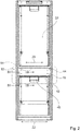
- the household appliance device 10 and parts thereof are in the Figures 2 to 7 shown in different views. It shows Figure 2 a front view of the household appliance device 10.
- FIG. 13 shows a sectional view along a line III-III in FIG Figure 2
- Figure 4 a corresponding section along a line IV-IV in Figure 2 shows.
- Figure 5 shows the front strip 14 in an individual view from behind
- Figure 6 shows an upper edge of the inner container 12 in a plan view from the front.
- Figure 7 finally shows the end strip 14 connected to the inner container 12 in an isometric rear view.
- the inner container 12 and the end strip 14 are connected to one another by a latching unit 16 of the household appliance device 10 by means of a latching mechanism.
- the further inner container 32 is connected to the end strip 14 by a further latching unit 44 by means of a further latching mechanism.
- the further inner container 32 is designed at least essentially identical to the inner container 12 and differs from the inner container 12 in terms of an extension length in a height direction.
- the further latching unit 44 is designed at least substantially identical to the latching unit 16, which is why a detailed description of the further latching unit 44 is dispensed with at this point and reference is made to the corresponding description of the latching unit 16.
- the latching unit 16 comprises a latching element 18 (cf. Figure 3 ).
- the latching element 18 is formed in one piece with the inner container 12.
- the latching element 18 is related to at least one side extension 20 of the inner container 12, which in the present case is parallel to a width direction 22 (cf. Figure 2 ), located at least essentially in the middle.
- the locking element 18 is based on the lateral extension 20 of the inner container 12 is elongated (cf. Figure 6 ).
- the locking element 18 is designed as a locking cam 24.
- the latching element 18 is arranged on a foam sealing element 26 (cf. Figures 3 and 6th ).
- the foam sealing element 26 is part of the inner container 12 and is designed in one piece with the inner container 12 (cf. Figure 3 ).
- the latching unit 16 comprises a counter-latching element 28 cooperating with the latching element 18 (cf. Figures 3 and 5 ).
- the counter-locking element 28 is formed in one piece with the end strip 14.
- the counter-locking element 28 is designed as a locking recess.
- the counter-locking element 28 is located at least essentially in the middle with respect to the lateral extension 20 of the inner container 12 (cf. Figure 5 ).
- the counter-locking element 28 has an extension length which is at least substantially identical to an extension length of the first locking element 18 related to the lateral extension 20 of the inner container 12 (cf. Figures 5 and 6th ).
- the counter-locking element 28 is arranged on a clamping spring section 30 of the end strip 14 (cf. Figure 3 ).
- the clamping spring section 30 receives the foam sealing element 26 in the assembled state. During a foaming process, the foam sealing element 26 prevents an insulating foam from escaping below and / or above the end strip 14.
- the latching unit 16 comprises a second latching element 34 (cf. Figure 4 ).
- the second latching element 34 is formed in one piece with the inner container 12.
- the second latching element 34 is designed as a latching cam 58.
- the second latching element 34 is arranged on the foam sealing element 26.
- the second latching element 34 is located eccentrically with respect to the lateral extension 20 of the inner container 12.
- the second latching element 34 is elongated in relation to the lateral extension 20 of the inner container 12.
- the second latching element 34 is located outside of an edge section area 36 of the inner container 12 (cf. Figure 6 ).
- the latching element 18 and the second latching element 34 have at least essentially the same minimum distances from an edge 48 of the inner container 12 which is parallel to the lateral extension 20 of the inner container 12 and delimits the cold space upward (cf. Figure 6 ).
- the latching unit 16 comprises a second counter-latching element 38 that cooperates with the second latching element 34.
- the second counter-latching element 38 is formed in one piece with the end strip 14.
- the second counter-locking element 38 is designed as a second locking recess.
- the second counter-locking element 38 is arranged on the clamping spring section 30 (cf. Figure 4 ).
- the second counter-locking element 38 is located off-center with respect to the lateral extension 20 of the inner container 12.
- the second counter-locking element 38 is elongated in relation to the lateral extension 20 of the inner container 12 (cf. Figure 5 ).
- the second counter-locking element 38 has a greater extension length in relation to the lateral extension 20 of the inner container 12 than the second locking element 34 (cf. Figures 5 and 6th ).
- the locking unit 16 comprises a third locking element 52.
- the third locking element 52 is formed in one piece with the inner container 12.
- the third latching element 52 is designed as a latching cam 60.
- the third latching element 52 is arranged on the foam sealing element 26.
- the third latching element 52 is located eccentrically with respect to the lateral extension 20 of the inner container 12.
- the third latching element 52 is elongated in relation to the lateral extension 20 of the inner container 12.
- the third latching element 52 is arranged outside of a further edge section area 56 of the inner container 12 (see FIG. 6).
- the latching element 18, the second latching element 34 and the third latching element 52 have at least essentially the same minimum distances from the edge 48 of the inner container 12, which is parallel to the lateral extension 20 of the inner container 12 and delimits the cold space upward
- the latching unit 16 comprises a third counter-latching element 54 that cooperates with the third latching element 52.
- the third counter-latching element 54 is formed in one piece with the end strip 14.
- the third counter-locking element 54 is located eccentrically with respect to the lateral extension 20 of the inner container 12.
- the third counter-locking element 54 is elongated in relation to the lateral extension 20 of the inner container 12 (cf. Figure 5 ).
- the end strip 14 When the end strip 14 is assembled with the inner container 12, the end strip 14 is first placed on the inner container 12 in such a way that the clamping spring section 30 of the end strip 14 can accommodate the foam sealing element 26 of the inner container 12. The second locking element 34 and the third engage Latching element 52 first of all into the respective cooperating counter-latching elements 38, 54.
- the end strip 14 is thereby initially fixed with respect to the inner container 12 in a direction running orthogonally to the lateral extension 20 of the inner container 12.
- the end strip 14 In a subsequent assembly step, the end strip 14 is displaced in the direction of the lateral extension 20 until the latching element 18 has latched into the counter-latching element 28. Thereafter, the end strip 14 is also fixed in relation to the inner container 12 in the direction of the lateral extension 20 of the inner container 12.
- the inner container 12 In this assembled state, the inner container 12 is connected to the end strip 14 by the latching unit 16 by means of the latching.
- Figure 7 the inner container 12 and the end strip 14 are shown in an assembled state and connected by the latching unit 16 by means of a latch. Also shows Figure 7 a possible arrangement of a frame heater 50.
Landscapes
- Engineering & Computer Science (AREA)
- Chemical & Material Sciences (AREA)
- Combustion & Propulsion (AREA)
- Physics & Mathematics (AREA)
- Mechanical Engineering (AREA)
- Thermal Sciences (AREA)
- General Engineering & Computer Science (AREA)
- Cookers (AREA)
Applications Claiming Priority (1)
| Application Number | Priority Date | Filing Date | Title |
|---|---|---|---|
| DE102019209959.9A DE102019209959A1 (de) | 2019-07-05 | 2019-07-05 | Haushaltsgerätevorrichtung |
Publications (1)
| Publication Number | Publication Date |
|---|---|
| EP3760954A1 true EP3760954A1 (fr) | 2021-01-06 |
Family
ID=71096581
Family Applications (1)
| Application Number | Title | Priority Date | Filing Date |
|---|---|---|---|
| EP20179995.4A Ceased EP3760954A1 (fr) | 2019-07-05 | 2020-06-15 | Dispositif formant appareil électroménager |
Country Status (2)
| Country | Link |
|---|---|
| EP (1) | EP3760954A1 (fr) |
| DE (1) | DE102019209959A1 (fr) |
Citations (10)
| Publication number | Priority date | Publication date | Assignee | Title |
|---|---|---|---|---|
| JPS5428501U (fr) * | 1977-07-28 | 1979-02-24 | ||
| JPS6086889U (ja) * | 1983-11-17 | 1985-06-14 | 株式会社東芝 | 断熱箱体 |
| DE20113468U1 (de) * | 2001-08-14 | 2001-10-11 | BSH Bosch und Siemens Hausgeräte GmbH, 81669 München | Gehäuse für ein Kältegerät |
| DE202008007362U1 (de) * | 2008-06-02 | 2008-08-21 | BSH Bosch und Siemens Hausgeräte GmbH | Kühlgutabstellfach |
| DE102008063390A1 (de) * | 2008-12-30 | 2010-07-01 | BSH Bosch und Siemens Hausgeräte GmbH | Kältegerät mit einem Ablageboden |
| EP2280235A2 (fr) * | 2009-07-10 | 2011-02-02 | BSH Bosch und Siemens Hausgeräte GmbH | Corps pour un appareil ménager |
| DE102009028789A1 (de) * | 2009-08-21 | 2011-02-24 | BSH Bosch und Siemens Hausgeräte GmbH | Kältegerät mit metallischer Stirnleiste |
| DE102011076486A1 (de) * | 2011-05-25 | 2012-11-29 | BSH Bosch und Siemens Hausgeräte GmbH | Haushaltskältegerät mit einer Stirnleiste |
| DE102013211734A1 (de) | 2013-06-21 | 2014-12-24 | BSH Bosch und Siemens Hausgeräte GmbH | Kältegerät mit einem innenbehälter |
| CN204494959U (zh) * | 2014-12-16 | 2015-07-22 | 广东奥马电器股份有限公司 | 一种改进中梁连接方式的冰箱 |
-
2019
- 2019-07-05 DE DE102019209959.9A patent/DE102019209959A1/de active Pending
-
2020
- 2020-06-15 EP EP20179995.4A patent/EP3760954A1/fr not_active Ceased
Patent Citations (10)
| Publication number | Priority date | Publication date | Assignee | Title |
|---|---|---|---|---|
| JPS5428501U (fr) * | 1977-07-28 | 1979-02-24 | ||
| JPS6086889U (ja) * | 1983-11-17 | 1985-06-14 | 株式会社東芝 | 断熱箱体 |
| DE20113468U1 (de) * | 2001-08-14 | 2001-10-11 | BSH Bosch und Siemens Hausgeräte GmbH, 81669 München | Gehäuse für ein Kältegerät |
| DE202008007362U1 (de) * | 2008-06-02 | 2008-08-21 | BSH Bosch und Siemens Hausgeräte GmbH | Kühlgutabstellfach |
| DE102008063390A1 (de) * | 2008-12-30 | 2010-07-01 | BSH Bosch und Siemens Hausgeräte GmbH | Kältegerät mit einem Ablageboden |
| EP2280235A2 (fr) * | 2009-07-10 | 2011-02-02 | BSH Bosch und Siemens Hausgeräte GmbH | Corps pour un appareil ménager |
| DE102009028789A1 (de) * | 2009-08-21 | 2011-02-24 | BSH Bosch und Siemens Hausgeräte GmbH | Kältegerät mit metallischer Stirnleiste |
| DE102011076486A1 (de) * | 2011-05-25 | 2012-11-29 | BSH Bosch und Siemens Hausgeräte GmbH | Haushaltskältegerät mit einer Stirnleiste |
| DE102013211734A1 (de) | 2013-06-21 | 2014-12-24 | BSH Bosch und Siemens Hausgeräte GmbH | Kältegerät mit einem innenbehälter |
| CN204494959U (zh) * | 2014-12-16 | 2015-07-22 | 广东奥马电器股份有限公司 | 一种改进中梁连接方式的冰箱 |
Also Published As
| Publication number | Publication date |
|---|---|
| DE102019209959A1 (de) | 2021-01-07 |
Similar Documents
| Publication | Publication Date | Title |
|---|---|---|
| EP2225513B1 (fr) | Dispositif de réfrigération | |
| EP2561292B1 (fr) | Vantail de porte, procédé de fabrication d'un vantail de porte et appareil frigorifique équipé d'un vantail de porte | |
| WO2007062934A2 (fr) | Appareil de refrigeration sans givre et procede de montage de cet appareil | |
| EP1397628A1 (fr) | Reservoir a marchandises a refrigerer pour appareil frigorifique | |
| EP2536984B1 (fr) | Appareil frigorifique comportant un dispositif de fixation pour un compresseur et procédé de montage d'un compresseur | |
| EP2467657B1 (fr) | Porte à poignée rapportée pour un appareil électroménager | |
| WO2019110307A1 (fr) | Appareil électroménager | |
| EP2536985B1 (fr) | Appareil électrique | |
| EP3211324B1 (fr) | Coussinet pour un appareil ménager comprenant un élément à ressort présentant une partie de recouvrement pour une ouverture d'insertion, module, appareil ménager et méthode de production d'un coussinet | |
| EP2697582A2 (fr) | Appareil frigorifique encastrable comportant un élément de montage | |
| EP3457056B1 (fr) | Compartiment de porte pour un appareil frigorifique | |
| EP3760954A1 (fr) | Dispositif formant appareil électroménager | |
| EP1895252B1 (fr) | Appareil de réfrigération et/ou de refroidissement | |
| DE102010039741A1 (de) | Kältegerät, insbesondere Haushaltskältegerät | |
| EP1030144B1 (fr) | Paroi avec éléments de soutien | |
| EP3336465A1 (fr) | Dispositif d'appareil ménager | |
| DE102018204776A1 (de) | Haushaltsgerätetür und Verfahren zu einer Montage der Haushaltsgerätetür | |
| EP2281159A1 (fr) | Porte pour appareil ménager | |
| DE102017213683A1 (de) | Hausgerätevorrichtung | |
| DE102011005892A1 (de) | Haushaltsgerät, insbesondere Kältegerät | |
| DE102018211263A1 (de) | Haushaltsgerätetür | |
| EP2561293B1 (fr) | Vantail de porte et appareil frigorifique équipé d'un vantail de porte | |
| DE102021213801A1 (de) | Haushaltsgerätevorrichtung, Haushaltsgerät und System | |
| EP4155634A1 (fr) | Appareil frigorifique, module compresseur pour un appareil frigorifique et procédé de montage du module compresseur | |
| EP3812672A1 (fr) | Appareil électroménager doté d'une charnière et charnière pour un appareil électroménager |
Legal Events
| Date | Code | Title | Description |
|---|---|---|---|
| PUAI | Public reference made under article 153(3) epc to a published international application that has entered the european phase |
Free format text: ORIGINAL CODE: 0009012 |
|
| STAA | Information on the status of an ep patent application or granted ep patent |
Free format text: STATUS: THE APPLICATION HAS BEEN PUBLISHED |
|
| AK | Designated contracting states |
Kind code of ref document: A1 Designated state(s): AL AT BE BG CH CY CZ DE DK EE ES FI FR GB GR HR HU IE IS IT LI LT LU LV MC MK MT NL NO PL PT RO RS SE SI SK SM TR |
|
| AX | Request for extension of the european patent |
Extension state: BA ME |
|
| STAA | Information on the status of an ep patent application or granted ep patent |
Free format text: STATUS: REQUEST FOR EXAMINATION WAS MADE |
|
| 17P | Request for examination filed |
Effective date: 20210706 |
|
| RBV | Designated contracting states (corrected) |
Designated state(s): AL AT BE BG CH CY CZ DE DK EE ES FI FR GB GR HR HU IE IS IT LI LT LU LV MC MK MT NL NO PL PT RO RS SE SI SK SM TR |
|
| STAA | Information on the status of an ep patent application or granted ep patent |
Free format text: STATUS: EXAMINATION IS IN PROGRESS |
|
| 17Q | First examination report despatched |
Effective date: 20230320 |
|
| STAA | Information on the status of an ep patent application or granted ep patent |
Free format text: STATUS: THE APPLICATION HAS BEEN REFUSED |
|
| 18R | Application refused |
Effective date: 20230519 |