EP3760803A1 - Schacht aus schachtelementen, die aus bauelementen hergestellt sind - Google Patents
Schacht aus schachtelementen, die aus bauelementen hergestellt sind Download PDFInfo
- Publication number
- EP3760803A1 EP3760803A1 EP20180894.6A EP20180894A EP3760803A1 EP 3760803 A1 EP3760803 A1 EP 3760803A1 EP 20180894 A EP20180894 A EP 20180894A EP 3760803 A1 EP3760803 A1 EP 3760803A1
- Authority
- EP
- European Patent Office
- Prior art keywords
- shaft
- connecting means
- trench
- component
- components
- Prior art date
- Legal status (The legal status is an assumption and is not a legal conclusion. Google has not performed a legal analysis and makes no representation as to the accuracy of the status listed.)
- Granted
Links
Images


Classifications
-
- E—FIXED CONSTRUCTIONS
- E03—WATER SUPPLY; SEWERAGE
- E03F—SEWERS; CESSPOOLS
- E03F1/00—Methods, systems, or installations for draining-off sewage or storm water
- E03F1/002—Methods, systems, or installations for draining-off sewage or storm water with disposal into the ground, e.g. via dry wells
- E03F1/005—Methods, systems, or installations for draining-off sewage or storm water with disposal into the ground, e.g. via dry wells via box-shaped elements
Definitions
- the present invention relates to a shaft for a trench made of shaft elements which are made from structural elements.
- the invention also relates to a trench shaft and a trench with such a trench shaft.
- Trenches are used to take up, store and release a fluid, especially rainwater.
- a shaft is provided for access to such a trench so that inspections, maintenance and cleaning of the trench can be carried out from there.
- These shafts are complex to manufacture from polymer material, in which they are either welded together from semi-finished products, or are produced in a blow molding process or in a rotary sintering process.
- the wall thicknesses of the shaft or shaft element are uneven, so that either the stability of these shafts or shaft elements is in need of improvement, or - in order to counteract this - a high wall thickness must be formed, which requires increased use of material.
- a further object of the invention is to specify a trench shaft and a trench with such a trench shaft.
- the first object of specifying a shaft made of shaft elements is achieved by the subject matter of claim 1.
- the shaft for a trench is composed of shaft elements made from a number of identical components, the component in Is essentially plate-shaped with a first side and a second opposite the first side Side, which are each arranged flat and essentially parallel to one another, with a third side and a fourth side opposite the third side, connection means being provided on the third side and on the fourth side, such that a first connection means on the third side and a second connecting means is formed on the fourth side, and a fifth side and a sixth side, wherein the sixth side is opposite the fifth side and both are arranged flat and substantially parallel to one another, on the fifth side and on the sixth side Connecting means are provided in such a way that a third connecting means is formed on the fifth side and a fourth connecting means is formed on the sixth side, the first connecting means on the third side and the second connecting means on the fourth side being formed congruently to one another in order to be between
- the shaft for a trench made of shaft elements that are made from a number of components can be designed to be particularly stable in this way. In this way, appropriate precautions can also be taken to ensure that the connection of the components to one another to form the shaft element is very solid.
- the shaft for a trench comprises two identical shaft elements which are connected to one another to form the shaft.
- the structural elements are designed in this way is that the first connecting means on the third side and the second connecting means on the fourth side are so congruent to one another that when establishing a connection state between two adjacent identical components, by connecting the first connecting means on the third side of the first component to the second connecting means on the fourth side of the second component or by connecting the second connecting means on the fourth side of the first component to the first connecting means on the third side of the second component, the components at an angle of 90 ° or about 90 ° based on the orientation of the each first side of the components are arranged.
- a very favorable further development of the present invention can consist in that the component is designed in such a way that the third connecting means on the fifth side and the fourth connecting means on the sixth side are designed so that they are congruent to one another when a connection state is established between two adjacent ones Components these are arranged in alignment or approximately in alignment with respect to the orientation of the respective first side of the components.
- a further advantageous development of the present invention can consist in that the component is designed in such a way that the first connecting means on the third side and the second connecting means on the fourth side have at least one engagement section, preferably two engagement sections.
- first and second connecting means By providing one or more engagement sections on the first and second connecting means, a particularly stable, secure and firm connection of two components arranged next to one another can be achieved and ensured.
- the component of the present invention can then be designed in a particularly practical manner if it is provided that a projection protrudes approximately perpendicularly from the second side, which projection is preferably formed at the end of the second side in the direction of the sixth side.
- a projection is particularly practical for the sections of a manhole or manhole element which, when installed in the ground, are oriented either in or against the direction of gravity. It is therefore particularly easy to close the shaft in or against the direction of gravity by arranging, attaching or assigning covers or adapters or similar devices to the projections or with the aid of the projections.
- the projection has, at least in sections, the contour of a circular ring, in particular the contour of a quarter circular ring.
- the component is designed in such a way that it consists of a polymer material or contains one, the polymer material being selected from a thermoplastic, in particular a polyolefin such as polypropylene (PP), polyethylene (PE), polybutylene (PB), their copolymers and mixed compositions.
- PP polypropylene
- PE polyethylene
- PB polybutylene
- Fiber-reinforced polymer materials and / or mineral-filled polymer materials can also be used to advantage.
- Long and short fibers are suitable as fibers. These can be selected from mineral fibers and synthetic reinforcing fibers. Examples are fibers of glass, polyamide, aramid, carbon, polyester and others.
- Natural too Reinforcing fibers from plants such as cotton, kapok, poplar fluff, bamboo, nettle, hemp, jute, linen, ramie, wood, sisal, coconut and hard Manila fiber can be used.
- Chalk, talc, mica, serpentine, vermiculite, muscovite, kaolinite and others are suitable as mineral fillers. Due to the fiber reinforcement and / or mineral filling of the polymer material, its range of properties can be adapted to the technical requirements or the requirements of the customer.
- the polymer materials referred to above are inert, resistant, long-lasting, resilient, comparatively easy to process, impact-resistant, flexible and inexpensive.
- a shaft or a shaft element is technically upgraded if it is provided that it is formed from a plurality of components - as described above.
- the component of the present invention can be produced in a polymer molding process such as an injection molding process or a rotational molding process or a rotational sintering process or a pressing process or a deep drawing process or an extrusion blow molding process or an additive manufacturing process such as a 3D printing process or a combination of the processes listed above.
- a polymer molding process such as an injection molding process or a rotational molding process or a rotational sintering process or a pressing process or a deep drawing process or an extrusion blow molding process or an additive manufacturing process such as a 3D printing process or a combination of the processes listed above.
- the processes mentioned above are suitable for producing a component according to the present invention in large numbers in a reproducible, dimensionally stable and inexpensive manner.
- the component is formed with the aid of a molding tool for molding the polymeric composition into the molded composition, the molding tool being an injection molding tool and / or a blow molding tool and / or a deep-drawing tool and / or is a pressing tool.
- a component can be manufactured precisely according to customer specifications in a simple, inexpensive and serial manner getting produced.
- the component is produced in an additive manufacturing process, such as a 3D printing process.
- an additive manufacturing process such as a 3D printing process.
- Such a process is suitable for producing a component according to the present invention in large numbers in a reproducible, dimensionally stable and cost-effective manner.
- the component is manufactured entirely or partially using a generative manufacturing process, for example by a 3-D printing process.
- a data processing machine-readable three-dimensional model can advantageously be used for the production.
- the invention also comprises a method for generating a data processing machine-readable three-dimensional model for use in a manufacturing method for a component.
- the method also includes, in particular, the input of data representing a component into a data processing machine and the use of the data to display a component as a three-dimensional model, the three-dimensional model being suitable for use in the manufacture of a component.
- the method also includes a technique in which the inputted data of one or more 3D scanners, which function either on contact or in a non-contact manner, in which case energy is emitted onto a component and the reflected energy is received, and in which a virtual three-dimensional Model of a component is generated using computer-aided design software.
- the manufacturing process can be a generative powder bed process, in particular selective laser melting (SLM), selective laser sintering (SLS), selective heat sintering (SHS), selective electron beam melting (electron beam melting - EBM / Electron Beam Additive Manufacturing - EBAM) or solidification of powder material by means of binder (binder jetting).
- the manufacturing process can be a generative free space process, in particular build-up welding, wax deposition modeling (WDM), Contour crafting, metal powder application processes (MPA), plastic powder application processes, cold gas spraying, electron beam welding (EBW) or melt coating processes such as fused deposition modeling (FDM) or fused filament fabrication (FFF).
- the manufacturing method can include a generative liquid material method, in particular stereolithography (SLA), digital light processing (DLP), multi jet modeling (MJM), polyjet modeling or liquid composite molding (LCM).
- the manufacturing method can include other generative layer construction methods, in particular laminated object modeling (LOM), 3D screen printing or light-controlled electrophoretic deposition.
- the present invention includes that two shaft elements, each formed from four components, can be connected to one another to form a shaft in such a way that each of the four fifth sides of the four components of a shaft element with the corresponding fifth side of the four components of the opposite shaft element through each third Connection means are brought into plug connection.
- This enables a firm connection of the two shaft elements.
- the orientation of the two shaft elements, which are connected to one another in the manner described above, takes place in such a way that the two openings are at a maximum distance from one another.
- the respective third connection means on the fifth side of the four components of a shaft element can be plugged into the fourth connection means on the sixth side of the four components of the opposite shaft element.
- the shaft elements are connected in such a way that the two openings are oriented close to one another.
- an orientation of two shaft elements can also be provided in such a way that the respective fourth connecting means of the sixth side of the four components one Shaft element can be brought into plug-in connection with the fourth connecting means on the sixth side of the four components of the opposite shaft element.
- the shaft elements are connected in such a way that the two openings are oriented directly adjacent to one another.
- the shaft elements can be stacked in any orientation, depending on the requirements that the arrangement of a trench shaft on a trench requires.
- the second object of specifying a trench shaft for a trench is achieved by the subject matter of claim 7.
- the trench shaft according to the invention comprising at least one shaft made of two shaft elements connected to one another, in which the openings are opposite one another and are maximally separated from one another, a closure element which closes an opening, an adapter which is arranged at the opening opposite to the opening closed by the closure element , and a pipe, in particular a corrugated pipe, which is connected to the adapter, is particularly advantageously suitable for equipping a trench.
- the closure part and / or the adapter and / or the corrugated tube contains a polymer material or consists of a polymer material, the polymer material being selected from a thermoplastic, in particular from a polyolefin such as Polypropylene (PP), polyethylene (PE), polybutylene (PB), their copolymers and mixed compositions.
- PP Polypropylene
- PE polyethylene
- PB polybutylene
- the third and final object of the invention to provide a trench with a trench shaft is achieved by the subject matter of claim 8.
- a trench is particularly technically upgraded if it is provided that the trench is constructed from trench elements and comprises at least one trench shaft as described above.
- the present invention finds wide application in the provision of shafts or shaft elements and in particular of trench shafts for Trench in order to create access to a trench in this way, in order to inspect, maintain and clean it, but also in order to supply fluid to or to discharge fluid from it.
- Such shafts or shaft elements and in particular trench shafts are easily and inexpensively accessible according to the present invention.
- a component 1 according to the present invention is shown in a schematic perspective illustration.
- the component 1 has a plate-shaped design.
- the component 1, which has approximately the shape of a cuboid, comprises six sides, a first side 2, a second side 3, a third side 4, a fourth side 5, a fifth side 6 and a sixth side 7, not shown here.
- the first side 2 and the second side 3 lie opposite one another, are flat and aligned approximately parallel to one another.
- the third side 4 and the fourth side 5 lie opposite one another and are aligned approximately parallel to one another.
- the fifth side 6 and the sixth side 7, not shown here are arranged opposite one another and aligned parallel to one another.
- Connection means 8, 9 are provided on the third side 4 and on the fourth side 5.
- the connecting means 8, 9 are designed such that a first connecting means 8 are formed on the third side 4 and a second connecting means 9 are formed on the fourth side 5.
- Connection means 10, 11 are formed on the fifth side 6 and on the sixth side 7.
- a third connecting means 10 is provided on the fifth side 6 and a fourth connecting means 11 is provided on the sixth side 7.
- the first connecting means 8 on the third side 4 and the second connecting means 9 on the fourth side 5 are designed to be congruent to one another in order to establish a connection state between two adjacent identical components 1, 1 ′, which will be shown later.
- the third connecting means 10 on the fifth side 6 and the fourth connecting means 11 on the sixth 7 side are designed to be congruent to one another in order to establish a connection state between two adjacent components 1, 1 ', which will be described in more detail later.
- a projection 14 protrudes perpendicularly from the second side 3 of the component 1.
- the projection 14 of the component 1 has in sections the contour of a circular ring, in particular the contour of a quarter circular ring. It is further provided that the first side 2 of the component 1 has a latching opening 18, into which, when a connection state is established between two adjacent identical components 1, 1 ', a latching lug 17, which is formed on the connecting means 10, 11 designed as projections, can snap in, whereby a firm connection state can be established.
- Fig. 2 a schematic plan view of a shaft element 102, which is made from four structural elements 1, 1 ', is shown.
- the reference symbols in the Fig. 2 correspond to those of the preceding Fig. 1 .
- the shaft element 102 is made of four identical components, of which only the adjacent components 1, 1 ′ will be discussed in more detail here, in that they are connected to their respective first connecting means 8 and second connecting means 9 in such a way that the second connecting means 9 of the first component 1 is connected to the first connecting means 8 of the adjacent same second component 1 '.
- the first component 1 is then correspondingly connected with its first connecting means 8 to a further component 1 ′ via its second connecting means 9, and so on.
- the second component 1 ′ is correspondingly further connected with its second connecting means 9 to an adjacent component, which is not provided with further reference numbers here, via its first connecting means 8.
- the further components 1 for the shaft element 102 which are identical to one another, are connected in an analogous manner.
- the inventive design of the component 1 results in an arrangement of four components 1, 1 ′, each connected to one another at an angle of 90 °, to the shaft element 102, which is square in plan view.
- Fig. 2 a detail A is shown.
- the projection 14 of the component 1 has the contour of a circular ring in sections, in particular the contour of a quarter circular ring, the four projections 14 complement one another in such a way that an opening 19 is formed in the shaft element 102, which is bordered by four projections 14. It goes without saying that the invention is not restricted to the fact that four components 1 can be connected to form a shaft element 102. Rather, by appropriately designing the components 1, it is also possible to combine three, five, six or more components to form shaft elements with a corresponding triangular, pentagonal, hexagonal, etc. cross section.
- FIG. 3 a schematic perspective view of a shaft 101 made up of two shaft elements 102, 102 connected to one another is shown.
- the reference symbols in the Fig. 3 correspond to those of the previous figures.
- two shaft elements 102 are formed from four components 1 each.
- the two manhole elements 102 created in this way are now connected to one another to form the manhole 101 that each of the four fifth sides 6 of the four components 1 of a manhole element 102 with the corresponding fifth side 6 of the four components 1 of the opposite manhole element 102 by third connecting means 10 in each case Plug connection are brought. This enables a fixed connection of the two shaft elements 102.
- the orientation of the two shaft elements 102 takes place in such a way that the two openings 19, of which only one, the upper opening 19, is shown, are at a maximum distance from one another.
- the respective third connection means 10 on the fifth side 6 of the four components 1 of a shaft element 102 with the fourth connection means 11 on the sixth side 7 of the four components 1 of the opposite shaft element 102 in Plug connection are brought.
- the shaft elements 102 are connected in such a way that the two openings 19 are oriented close to one another.
- the projections and recesses that form the connecting means 10, 11 are dimensioned and positioned in such a way that a projection can be inserted into a recess along each side 6, 7 in order to establish a connection between two adjacent identical components 1, 1 of the two shaft elements 102, 102 to produce. It is also provided that the second side 3 of the component 1 has latching openings 18 into which, when a connection state is established between two adjacent identical components 1, 1 ′, latching lugs 17, which are formed as projections on the connecting means 10, 11, can snap , whereby a firm connection state can be established.
- Fig. 4 a schematic sectional side view of a shaft 101 made up of two shaft elements 102, 102 connected to one another, each made of four structural elements 1, and details thereof.
- the reference symbols in the Fig. 4 correspond to those of the previous figures.
- Two shaft elements 102 connected to one another are shown here.
- an adapter 105 is connected to the upwardly pointing opening 19 of the upper shaft element 102, which is bordered by the projections 14, which has a collar 107 extending around its outer circumference and can thus be easily placed on the projections 14 .
- holding elements 106 are formed which engage behind the projections 14 in a latching manner.
- the collar 107 can advantageously be used to fasten a cover, for example in the form of a film, which encloses the trench 200 and the shaft element 102, for example by a welding process to the collar 107 in a fluid-tight manner.
- a cover for example in the form of a film
- the opening 19 of the Fig. 4 The lower shaft element 102 shown, which lies opposite the opening 19 with the adapter 105, is closed by a closure part 103.
- the closure part 103 is designed in the form of a plate with a round cross section, which has latching elements 104 on the edge. In detail C, it is shown here that the latching elements 104 of the closure part 103 engage behind the projections 14 in a latching manner.
- An example is in the Fig.
- the closure part 103 is inserted from below into the opening 19 of the shaft element 102.
- the closure part 103 is inserted into the opening 19 from above, that is to say “from the inside of the shaft element 102”.
- Fig. 5 a schematic side view of a trench shaft 300 is shown.
- the reference symbols in the Fig. 5 correspond to those of the previous figures.
- the adapter 105 which is attached to the shaft element 102, is designed in such a way that it can receive a corrugated pipe 120 in order to provide access, for example from the earth's surface through the corrugated pipe 120 and the shaft elements 102 to the connected one, not shown here To create trench 200.
- FIG. 3 is a schematic perspective view of the trench shaft 300 from FIG Fig. 5 shown.
- the reference symbols in the Fig. 6 correspond to those of the previous figures. In this illustration, the view can be directed to the lower part of the trench shaft 300.
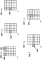
- Fig. 7 a - e each shows a schematic plan view of a trench 200 with a shaft 101.
- the reference symbols in the Fig. 7 a - e correspond to those of the previous figures.
- four trenches 200 are shown schematically, each of which is formed according to a similar scheme in a matrix arrangement of trench elements 201.
- 19 or 20 trench elements 201 are arranged next to one another in such a way that a layer of a rectangular trench 200 is formed.
- the trench elements 201 are known per se from the prior art, are generally formed from a polymer material and can be firmly joined together by suitable connecting means in at least two, mostly in three spatial directions.
- FIG Fig. 7 For the trench shaft 300 required for the trench 200, there are in principle four possibilities for the arrangement, which are shown in FIG Fig. 7 are shown at a - e.
- the trench shaft 300 is arranged at a corner position of the trench 200.
- the flushing and distribution channels in the trench elements 201 which are shown schematically as a line arranged centrally in the trench element 201, are arranged horizontally and vertically to the plane of the drawing.
- the Figure 7b shows the arrangement of the trench shaft 300 in the layer of trench elements 201, which form the outer edge of the trench 200.
- the flushing and distribution channel runs horizontally.
- the Figure 7c shows the arrangement of the trench shaft 300 in the layer of trench elements 201, which form the outer edge of the trench 200, with the flushing and distribution channel running in the vertical direction.
- the trench shaft 300 is arranged in front of an outer edge of the trench 200.
- the flushing and distribution channel runs horizontally.
- the trench shaft 300 is arranged within the arrangement of trench elements 201 of the trench 200, with a horizontal and vertical arrangement of the flushing and distribution channels being formed.
- the trench elements 201 were not marked again, as shown in FIG Figure 7a is the case, since the facts of the Figures 7b-d is the same as with Figure 7a .
- the trench elements 201 can also be stacked perpendicular to the plane of the drawing and that the number of trench elements 201 according to FIG Fig. 7 can also be any other.
Landscapes
- Health & Medical Sciences (AREA)
- Life Sciences & Earth Sciences (AREA)
- Engineering & Computer Science (AREA)
- Hydrology & Water Resources (AREA)
- Public Health (AREA)
- Water Supply & Treatment (AREA)
- Shafts, Cranks, Connecting Bars, And Related Bearings (AREA)
- Golf Clubs (AREA)
Abstract
Description
- Die vorliegende Erfindung betrifft einen Schacht für eine Rigole aus Schachtelementen, welche aus Bauelementen hergestellt sind.
Weiterhin betrifft die Erfindung einen Rigolenschacht und eine Rigole mit einem solchen Rigolenschacht. - Rigolen dienen zur Aufnahme, Speicherung und Abgabe eines Fluids, insbesondere von Regenwasser. Für den Zugang zu einer solchen Rigole wird ein Schacht vorgesehen, um von diesem aus Inspektionen, Wartungen und Reinigungen der Rigole vornehmen zu können. Diese Schächte sind aus Polymermaterial aufwendig zu fertigen, in dem diese entweder aus Halbzeugen zusammengeschweißt werden, oder in einem Blasverfahren oder in einem Rotationssinterverfahren hergestellt werden. Insbesondere beim Blasverfahren und beim Rotationssinterverfahren sind die Wandstärken des Schachtes oder Schachtelements ungleichmäßig, sodass entweder die Stabilität dieser Schächte oder Schachtelemente verbesserungswürdig ist, oder - um dem zu begegnen - ist eine hohe Wandstärke auszubilden, was einen erhöhten Materialeinsatz erfordert.
- Hier setzt die Erfindung ein, die es sich zur Aufgabe gemacht hat, einen Schacht für eine Rigole aus Schachtelementen anzugeben, welche aus Bauelementen hergestellt sind, mit dem die vorstehend geschilderten Nachteile des Standes der Technik überwunden sind. Weiterhin ist es Aufgabe der Erfindung, einen Rigolenschacht und eine Rigole mit einem solchen Rigolenschacht anzugeben.
- Die Lösung der ersten Aufgabe, einen Schacht aus Schachtelementen anzugeben, geschieht durch den Gegenstand des Anspruchs 1.
- Es wurde im Rahmen der vorliegenden Erfindung erkannt, dass ein Schacht oder ein Schachtelement für eine Rigole die Aufgabe vollständig löst, wenn vorgesehen ist, dass der Schacht für eine Rigole aus Schachtelementen, hergestellt aus einer Anzahl gleicher Bauelemente, zusammengesetzt ist, wobei das Bauelement im Wesentlichen plattenförmig ausgebildet ist mit einer ersten Seite und einer der ersten Seite gegenüberliegenden zweiten Seite, die jeweils flach und im Wesentlichen parallel zueinander angeordnet sind, mit einer dritten Seite und einer der dritten Seite gegenüberliegenden vierten Seite, wobei an der dritten Seite und an der vierten Seite Verbindungsmittel vorgesehen sind, derart, dass ein erstes Verbindungsmittel an der dritten Seite und ein zweites Verbindungsmittel an der vierten Seite ausgebildet ist, und einer fünften Seite und einer sechsten Seite, wobei die sechste Seite der fünften Seite gegenüberliegt und beide jeweils flach und im Wesentlichen parallel zueinander angeordnet sind, wobei an der fünften Seite und an der sechsten Seite Verbindungsmittel vorgesehen sind, derart, dass ein drittes Verbindungsmittel an der fünften Seite und ein viertes Verbindungsmittel an der sechsten Seite ausgebildet ist, wobei das erste Verbindungsmittel an der dritten Seite und das zweite Verbindungsmittel an der vierten Seite kongruent zueinander ausgebildet sind, um zwischen zwei benachbarten gleichen Bauelementen einen Verbindungszustand in einer Raumrichtung herzustellen, und wobei das dritte Verbindungsmittel an der fünften Seite und das vierte Verbindungsmittel an der sechsten Seite kongruent zueinander ausgebildet sind, um zwischen zwei benachbarten Bauelementen einen Verbindungszustand in einer anderen Raumrichtung herzustellen.
- Der Schacht für eine Rigole aus Schachtelementen, die aus einer Anzahl an Bauelementen hergestellt sind, kann auf diese Weise besonders stabil ausgelegt werden. Es können auf diese Weise auch entsprechende Vorkehrungen getroffen werden, dass die Verbindung der Bauelemente untereinander zu dem Schachtelement sehr fest gestaltet ist.
- Hierdurch ist es möglich, die Nachteile des Standes zu überwinden und einen Schacht aus Schachtelementen, hergestellt aus Bauelementen, bereitzustellen, welcher bei maximaler Stabilität den geringsten Materialeinsatz erfordert.
- In der einfachsten Ausbildung der vorliegenden Erfindung umfasst der Schacht für eine Rigole zwei gleiche Schachtelemente, die miteinander zum Schacht verbunden sind.
- Es ist im Rahmen der vorliegenden Erfindung auch möglich, dass an diesem Schacht aus zwei Schachtelementen weitere Schachtelemente angeordnet und mit diesem bzw. mit einem benachbarten Schachtelement verbunden sind.
- In einer sehr vorteilhaften Weiterbildung der vorliegenden Erfindung kann vorgesehen sein, dass bei dem Schacht für eine Rigole aus Schachtelementen das Bauelemente derart ausgestaltet ist, dass das erste Verbindungsmittel an der dritten Seite und das zweite Verbindungsmittel an der vierten Seite derartig kongruent zueinander ausgebildet sind, dass bei der Herstellung eines Verbindungszustands zwischen zwei benachbarten gleichen Bauelementen, durch Verbinden des ersten Verbindungsmittels an der dritten Seite des ersten Bauelements mit dem zweiten Verbindungsmittel an der vierten Seite des zweiten Bauelements oder durch Verbinden des zweiten Verbindungsmittels an der vierten Seite des ersten Bauelements mit dem ersten Verbindungsmittel an der dritten Seite des zweiten Bauelements die Bauelemente unter einem Winkel von 90° oder etwa 90° bezogen auf die Ausrichtung der jeweils ersten Seite der Bauelemente angeordnet sind.
- Durch die vorstehend geschilderte Maßnahme ist es möglich, in einfacher Weise durch Verbinden einzelner Bauelemente einen Schacht oder ein Schachtelement herzustellen. Insbesondere kann auf diese Weise aus vier einzelnen gleichen Bauelementen, die miteinander jeweils unter einem Winkel von 90° oder etwa 90° verbunden werden, ein solcher Schacht oder ein solches Schachtelement zusammengebaut werden.
- Eine sehr günstige Weiterentwicklung der vorliegenden Erfindung kann darin bestehen, dass das Bauelement derartig ausgebildet ist, dass das dritte Verbindungsmittel an der fünften Seite und das vierte Verbindungsmittel an der sechsten Seite derartig kongruent zueinander ausgebildet sind, dass bei der Herstellung eines Verbindungszustands zwischen zwei benachbarten gleichen Bauelementen diese fluchtend oder etwa fluchtend bezogen auf die Ausrichtung der jeweils ersten Seite der Bauelemente angeordnet sind.
- Mit dieser Maßnahme kann in einfacher Weise ein Stapeln von Schachtelementen erfolgen, in dem diese übereinander fluchtend angeordnet werden und mithilfe der Verbindungsmittel der Verbindungszustand hergestellt wird, sodass die einzelnen Schachtelemente fest miteinander verbunden sind.
- Eine weitere vorteilhafte Fortbildung der vorliegenden Erfindung kann darin bestehen, dass das Bauelement derartig ausgebildet ist, dass das erste Verbindungsmittel an der dritten Seite und das zweite Verbindungsmittel an der vierten Seite wenigstens einen Hintergreifabschnitt, bevorzugt zwei Hintergreifabschnitte, aufweist.
- Durch das Vorsehen eines oder mehrerer Hintergreifabschnitte an den ersten und zweiten Verbindungsmitteln kann eine besonders stabile, sichere und feste Verbindung von zwei nebeneinander angeordneten Bauelementen erreicht und sichergestellt werden.
- Das Bauelement der vorliegenden Erfindung kann dann in besonders praktikabler Weise ausgebildet sein, wenn vorgesehen ist, dass von der zweiten Seite ein Vorsprung etwa senkrecht hervorsteht, der bevorzugt am Ende der zweiten Seite in Richtung der sechsten Seite ausgebildet ist.
Ein solcher Vorsprung ist besonders praktikabel für die Abschnitte eines Schachtes oder Schachtelements, die bei Einbau im Erdboden entweder in oder entgegen der Schwerkraftrichtung ausgerichtet sind. Es ist damit besonders einfach, einen Abschluss des Schachtes in oder entgegen der Schwerkraftrichtung vorzunehmen, in dem an den Vorsprüngen oder unter Zuhilfenahme der Vorsprünge Deckel oder Adapter oder ähnliche Einrichtungen angeordnet, befestigt oder diesen zugeordnet werden. - In einer weiteren Fortbildung der vorliegenden Erfindung kann in vorteilhafter Weise vorgesehen sein, dass der Vorsprung zumindest abschnittsweise die Kontur eines Kreisrings, insbesondere die Kontur eines Viertelkreisrings aufweist.
Durch das Vorsehen einer Kontur des Vorsprungs zumindest abschnittsweise in Form eines Kreisrings, insbesondere in Form eines Viertelkreisrings, kann bei der Herstellung eines Schachtes oder eines Schachtelements aus vier gleichen Bauelementen eine Öffnung, die von den Vorsprüngen umgrenzt ist, ausgebildet werden. Eine solche Öffnung eines Schachtes oder Schachtelements ist vorteilhaft als Zugang zu dem Schacht oder Schachtelement zu nutzen. - Bei der vorliegenden Erfindung kann es sich als sehr günstig erweisen, wenn vorgesehen ist, dass das Bauelement derart ausgebildet ist, dass dieses aus einem Polymermaterial besteht oder ein solches enthält, wobei das Polymermaterial ausgewählt ist aus einem Thermoplasten, insbesondere aus einem Polyolefin, wie Polypropylen (PP), Polyethylen (PE), Polybutylen (PB), deren Copolymere und Mischzusammensetzungen.
Mit Vorteil können auch faserverstärkte Polymermaterialien und / oder mineralgefüllte Polymermaterialien eingesetzt werden. Als Fasern eignen sich Lang- und Kurzfasern. Diese können ausgewählt sein aus Mineralfasern und synthetische Verstärkungsfasern. Beispiele sind Fasern von Glas, Polyamid, Aramid, Kohle, Polyester und anderen. Auch natürliche Verstärkungsfasern von Pflanzen, wie Baumwolle, Kapok, Pappelflaum, Bambus, Brennessel, Hanf, Jute, Leinen, Ramie, Holz, Sisal, Kokos und Manila-Hartfaser können eingesetzt werden. Als Mineralfüllstoffe eignen sich Kreide, Talkum, Glimmer, Serpentin, Vermiculit, Muskovit, Kaolinit und andere.
Durch die Faserverstärkung und / oder Mineralfüllung des Polymermaterials kann dessen Eigenschaftsspektrum an die technischen Erfordernisse bzw. die Anforderungen des Kunden angepasst werden. - Die vorstehend bezeichneten Polymermaterialien sind inert, resistent, langlebig, widerstandsfähig, vergleichsweise einfach verarbeitbar, schlagfest, flexibel und kostengünstig.
- Die weitere Aufgabe der vorliegenden Erfindung, einen Schacht oder ein Schachtelement anzugeben, erfährt ihre Lösung durch den Gegenstand des Anspruchs 8.
- Es wurde bei der vorliegenden Erfindung erkannt, dass ein Schacht oder ein Schachtelement dann technisch aufgewertet ist, wenn vorgesehen ist, dass dieser aus einer Mehrzahl von Bauelementen - wie vorstehend beschrieben - gebildet ist.
- Das Bauelement der vorliegenden Erfindung kann in einem Polymerformgebungsprozess, wie einem Spritzgussprozess oder einem Rotationsgießprozess oder einem Rotationssinterprozess oder einem Pressprozess oder einem Tiefziehprozess oder einem Extrusionsblasprozess oder einem additiven Fertigungsprozess, wie einem 3D-Druckprozess, oder einer Kombination der vorstehend aufgeführten Prozesse hergestellt sein.
Die vorstehend genannten Prozesse sind geeignet, ein Bauelement gemäß vorliegender Erfindung in großer Stückzahl reproduzierbar, maßhaltig und kostengünstig herzustellen. - Hierdurch werden Bauelemente bereitgestellt, die äußerst widerstandsfähig und fest sind, und die Ansprüche der Kunden bzw. die Vorgaben der einschlägigen Spezifikationen für ihre Anwendung erfüllen.
- Es kann sich im Rahmen der vorliegenden Erfindung als sehr vorteilhaft ergeben, wenn vorgesehen ist, dass das Bauelement mit Hilfe eines Formwerkzeugs zur Formung der polymeren Zusammensetzung zur geformten Zusammensetzung gebildet ist, wobei das Formwerkzeug ein Spritzgusswerkzeug und / oder ein Blaswerkzeug und / oder ein Tiefziehwerkzeug und / oder ein Presswerkzeug ist.
- Durch die Wahl eines Formwerkzeugs zur Formung der polymeren Zusammensetzung zur geformten Zusammensetzung, wobei das Formwerkzeug ein Spritzgusswerkzeug und / oder ein Blaswerkzeug und / oder ein Tiefziehwerkzeug und / oder ein Presswerkzeug ist, kann ein Bauelement genau nach den Kundenspezifikationen in einfacher, kostengünstiger und serieller Weise hergestellt werden.
- Es kann sich im Rahmen der vorliegenden Erfindung weiterhin als sehr praktikabel ergeben, wenn vorgesehen ist, dass das Bauelement in einem additiven Fertigungsprozess, wie einem 3D-Druckprozess hergestellt ist.
Ein solcher Prozess ist geeignet, ein Bauelement gemäß vorliegender Erfindung in großer Stückzahl reproduzierbar, maßhaltig und kostengünstig herzustellen. - So kann insbesondere vorgesehen sein, dass das Bauelement ganz oder teilweise unter Verwendung eines generativen Fertigungsverfahrens, beispielsweise durch ein 3-D-Druckverfahren, hergestellt ist.
Hierzu kann mit Vorteil ein datenverarbeitungsmaschinenlesbares dreidimensionales Modell für die Herstellung genutzt werden.
Die Erfindung umfasst auch ein Verfahren zur Erzeugung eines datenverarbeitungsmaschinenlesbaren dreidimensionalen Modells zur Verwendung in einem Herstellungsverfahren für ein Bauelement. Hierbei umfasst das Verfahren insbesondere auch die Eingabe von Daten, die ein Bauelement darstellen, in eine Datenverarbeitungsmaschine und die Nutzung der Daten, um ein Bauelement als dreidimensionales Modell darzustellen, wobei das dreidimensionale Modell geeignet ist zur Nutzung bei der Herstellung eines Bauelements. Ebenfalls umfasst ist bei dem Verfahren eine Technik, bei der die eingegebenen Daten eines oder mehrerer 3D-Scanner, die entweder auf Berührung oder berührungslos funktionieren, wobei bei letzteren Energie auf ein Bauelement abgegeben wird und die reflektierte Energie empfangen wird, und wobei ein virtuelles dreidimensionales Modell eines Bauelements unter Verwendung einer computer-unterstützten Design-Software erzeugt wird.
Das Fertigungsverfahren kann ein generatives Pulverbettverfahren, insbesondere selektives Laserschmelzen (SLM), selektives Lasersintern (SLS), selektives Hitzesintern (Selective Heat Sintering - SHS), selektives Elektronenstrahlschmelzen (Electron Beam Melting - EBM / Electron Beam Additive Manufacturing - EBAM) oder Verfestigen von Pulvermaterial mittels Binder (Binder Jetting) umfassen. Das Fertigungsverfahren kann ein generatives Freiraumverfahren, insbesondere Auftragsschweißen, Wax Deposition Modeling (WDM), Contour Crafting, Metall-Pulver-Auftragsverfahren (MPA), Kunststoff-Pulver-Auftragsverfahren, Kaltgasspritzen, Elektronenstrahlschmelzen (Electron Beam Welding - EBW) oder Schmelzeschichtungsverfahren wie Fused Deposition Modeling (FDM) oder Fused Filament Fabrication (FFF) umfassen. Das Fertigungsverfahren kann ein generatives Flüssigmaterialverfahren, insbesondere Stereolithografie (SLA), Digital Light Processing (DLP), Multi Jet Modeling (MJM), Polyjet Modeling oder Liquid Composite Moulding (LCM) umfassen. Ferner kann das Fertigungsverfahren andere generative Schichtaufbauverfahren, insbesondere Laminated Object Modelling (LOM), 3D-Siebdruck oder die Lichtgesteuerte Elektrophoretische Abscheidung umfassen. - Weiterhin ist durch die vorliegende Erfindung umfasst, dass zwei Schachtelemente, gebildet aus jeweils vier Bauelementen derart miteinander zu einem Schacht verbindbar sind, dass jede der vier fünften Seiten der vier Bauelemente eines Schachtelements mit der korrespondierenden fünften Seite der vier Bauelemente des gegenüberliegenden Schachtelements durch jeweils dritten Verbindungsmittel in Steckverbindung gebracht sind.
Hierdurch ist eine feste Verbindung der beiden Schachtelemente ermöglicht.
Die Orientierung der beiden Schachtelemente, die miteinander in der vorstehend geschilderten Weise verbunden sind, erfolgt dabei so, dass die beiden Öffnungen maximal voneinander entfernt sind.
In einer anderen Orientierung von zwei Schachtelementen kann vorgesehen sein, dass die jeweils dritten Verbindungsmittel der fünften Seite der vier Bauelemente eines Schachtelements mit den vierten Verbindungsmitteln an der sechsten Seite der vier Bauelemente des gegenüberliegenden Schachtelements in Steckverbindung bringbar sind.
Hierbei sind die Schachtelemente derartig verbunden, dass die beiden Öffnungen nahe zueinander orientiert sind. - Es ist weiterhin möglich, weitere Schachtelemente an den beiden vorstehend beschriebenen Schächten anzuordnen, wobei dies in stapelnder Weise geschieht, so dass jeweils die Öffnung des zu stapelnden, also in Verbindung mit dem Schacht zu bringen Schachtelements entweder maximal entfernt oder nahe zu der nächsten Öffnung des Schachts orientiert ist. Die Stapelung kann so beliebig oft wiederholt werden, wobei man sich bei der Anzahl der gestapelten Schachtelemente an der Höhe einer Rigole orientieren wird.
- Weiterhin kann auch eine Orientierung von zwei Schachtelementen derart vorgesehen sein, dass die jeweils vierten Verbindungsmittel der sechsten Seite der vier Bauelemente eines Schachtelements mit den vierten Verbindungsmitteln an der sechsten Seite der vier Bauelemente des gegenüberliegenden Schachtelements in Steckverbindung bringbar sind. Hierbei sind die Schachtelemente derartig verbunden, dass die beiden Öffnungen unmittelbar aneinander angrenzend zueinander orientiert sind.
- Durch die vorstehend geschilderten Möglichkeiten kann ein Stapeln der Schachtelemente in beliebiger Orientierung je nach den Notwendigkeiten, die die Anordnung eines Rigolenschachts an einer Rigole verlangt, vorgenommen werden.
- Die Lösung der zweiten Aufgabe, einen Rigolenschacht für eine Rigole anzugeben, geschieht durch den Gegenstand des Anspruchs 7.
Der erfindungsgemäße Rigolenschacht, umfassend wenigstens einen Schacht aus zwei miteinander verbundenen Schachtelementen, bei denen die Öffnungen einander gegenüberliegen und maximal voneinander entfernt sind, ein Verschlusselement, welches eine Öffnung verschließt, einen Adapter, der an der zur durch das Verschlusselement verschlossenen Öffnung gegenüberliegenden Öffnung angeordnet ist, und ein Rohr, insbesondere ein Wellrohr, das mit dem Adapter verbunden ist, ist in ganz besonders vorteilhafter Weise geeignet für die Ausrüstung einer Rigole.
Ein solcher Schacht ist ganz besonders vorteilhaft ausgebildet, wenn vorgesehen ist, dass das Verschlussteil und / oder der Adapter und / oder das Wellrohr ein Polymermaterial enthält oder aus einem Polymermaterial besteht, wobei das Polymermaterial ausgewählt ist aus einem Thermoplasten, insbesondere aus einem Polyolefin, wie Polypropylen (PP), Polyethylen (PE), Polybutylen (PB), deren Copolymere und Mischzusammensetzungen. - Die Lösung der dritten und letzten Aufgabe der Erfindung, eine Rigole mit einem Rigolenschacht anzugeben, geschieht durch den Gegenstand des Anspruchs 8.
Im Rahmen der vorliegenden Erfindung wurde erkannt, dass eine Rigole dann ganz besonders technische aufgewertet ist, wenn vorgesehen ist, dass die Rigole aus Rigolenelementen aufgebaut ist, und wenigstens einem Rigolenschacht gemäß vorstehender Beschreibung umfasst. - Anwendung findet die vorliegende Erfindung in breitem Umfang bei der Zurverfügungstellung von Schächten oder Schachtelementen und insbesondere von Rigolenschächten für Rigolen, um auf diese Weise einen Zugang zu einer Rigole zu schaffen, um diese zu inspizieren, zu warten und zu reinigen, aber auch um dieser Fluid zuzuführen oder um von dieser Fluid abzuführen.
- Solche Schächte oder Schachtelemente und insbesondere Rigolenschächte sind gemäß vorliegender Erfindung einfach und kostengünstig zugänglich.
- Zum Anschluss eines Rigolenschachtes an eine Rigole sind entsprechende Öffnungen anzubringen, um einen ungehinderten Fluidtransport zwischen dem Schacht und der Rigole zu ermöglichen.
- Weitere wichtige Merkmale und Vorteile der Erfindung ergeben sich aus den Unteransprüchen, aus den Figuren und aus der zugehörigen Figurenbeschreibung.
- Es versteht sich, dass die vorstehend genannten und die nachstehend noch zu erläuternden Merkmale nicht nur in der jeweils angegebenen Kombination, sondern auch in anderen Kombinationen oder in Alleinstellung verwendbar sind, ohne den Rahmen der vorliegenden Erfindung zu verlassen.
- Die vorliegende Erfindung wird anhand der beigefügten Figuren näher beschrieben.
- Hierzu zeigt:
- Fig. 1
- eine schematische perspektivische Darstellung eines Bauelements gemäß der vorliegenden Erfindung;
- Fig. 2
- eine schematische Aufsicht auf ein Schachtelement, das aus vier Bauelementen hergestellt ist und einem Detail daraus;
- Fig. 3
- eine schematische perspektivische Ansicht eines Schachts aus zwei miteinander verbundenen Schachtelementen, die jeweils aus vier Bauelementen hergestellt sind;
- Fig. 4
- eine schematische seitliche geschnittene Ansicht eines Schachts aus zwei miteinander verbundenen Schachtelementen, die jeweils aus vier Bauelementen hergestellt sind, und Details daraus;
- Fig. 5
- eine schematische Seitenansicht eines Schachtes;
- Fig. 6
- eine schematische perspektivische Ansicht des Schachtes aus
Fig. 5 ; - Fig. 7 a-e
- jeweils eine schematische Aufsicht auf eine Rigole mit einem Schacht.
- In
Fig. 1 ist in einer schematischen perspektivischen Darstellung ein Bauelement 1 gemäß der vorliegenden Erfindung gezeigt.
Das Bauelement 1 weist eine plattenförmige Ausbildung auf.
Das Bauelement 1, das etwa die Form eines Quaders besitzt, umfasst sechs Seiten, eine erste Seite 2, eine zweite Seite 3, eine dritte Seite 4, eine vierte Seite 5, eine fünfte Seite 6 und eine hier nicht gezeigte sechste Seite 7.
Die erste Seite 2 und die zweite Seite 3 liegen einander gegenüber, sind flach und etwa parallel zueinander ausgerichtet.
Die dritte Seite 4 und die vierte Seite 5 liegen einander gegenüber und sind etwa parallel zueinander ausgerichtet.
Ebenso sind die fünfte Seite 6 und die hier nicht gezeigte sechste Seite 7 einander gegenüberliegend und parallel zueinander ausgerichtet angeordnet.
An der dritten Seite 4 und an der vierten Seite 5 sind Verbindungsmittel 8, 9 vorgesehen. Die Verbindungsmittel 8, 9 sind derart ausgebildet, dass ein erstes Verbindungsmittel 8 an der dritten Seite 4 und ein zweites Verbindungsmittel 9 an der vierten Seite 5 ausgeformt sind.
An der fünften Seite 6 und an der sechsten Seite 7 sind Verbindungsmittel 10, 11 ausgebildet. Hierzu ist ein drittes Verbindungsmittel 10 an der fünften Seite 6 und ein viertes Verbindungsmittel 11 an der sechsten Seite 7 vorgesehen.
Das erste Verbindungsmittel 8 an der dritten Seite 4 und das zweite Verbindungsmittel 9 an der vierten Seite 5 sind kongruent zueinander ausgebildet, um zwischen zwei benachbarten gleichen Bauelementen 1,1' einen Verbindungszustand herzustellen, was später noch gezeigt wird.
Das dritte Verbindungsmittel 10 an der fünften Seite 6 und das vierte Verbindungsmittel 11 an der sechsten 7 Seite sind kongruent zueinander gestaltet, um zwischen zwei benachbarten Bauelementen 1,1' einen Verbindungszustand herzustellen, was später noch näher beschrieben wird.
Von der zweiten Seite 3 des Bauelements 1 steht ein Vorsprung 14 senkrecht hervor. - Der Vorsprung 14 des Bauelements 1 weist abschnittsweise die Kontur eines Kreisrings, insbesondere die Kontur eines Viertelkreisrings auf.
Es ist weiterhin vorgesehen, dass die erste Seite 2 des Bauelements 1 eine Rastöffnung 18 aufweist, in die bei Herstellung eines Verbindungszustands zwischen zwei benachbarten gleichen Bauelementen 1, 1' eine Rastnase 17, die an den als Vorsprüngen ausgebildeten Verbindungsmitteln 10, 11 ausgebildet sind, einschnappen kann, wodurch ein fester Verbindungszustand herstellbar ist. - In
Fig. 2 ist eine schematische Aufsicht auf ein Schachtelement 102, das aus vier Bauelementen 1,1' hergestellt ist, gezeigt.
Die Bezugszeichen in derFig. 2 entsprechen denen der vorangehendenFig. 1 .
Das Schachtelement 102 ist aus vier gleichen Bauelementen, von denen hier nur auf die benachbarten Bauelemente 1,1' näher eingegangen wird, hergestellt, indem diese an ihren jeweiligen ersten Verbindungsmitteln 8 und zweiten Verbindungsmitteln 9 verbunden sind, und zwar so, dass das zweite Verbindungsmittel 9 des ersten Bauelements 1 mit dem ersten Verbindungsmittel 8 des benachbarten gleichen zweiten Bauelements 1' verbunden ist. Das erste Bauelement 1 ist dann entsprechend mit seinem ersten Verbindungsmittel 8 mit einem weiteren Bauelement 1' via dessen zweiten Verbindungsmittel 9 verbunden, und so fort. Das zweite Bauelement 1' ist entsprechend mit seinem zweiten Verbindungsmittel 9 mit einem benachbarten hier nicht weiter mit Bezugszeichen versehenen Bauelement via dessen ersten Verbindungsmittel 8 weiter verbunden.
Es versteht sich, dass die weiteren Bauelemente 1 für das Schachtelement 102, die ja untereinander gleich sind, in analoger Weise verbunden sind.
Durch die erfindungsgemäße Ausbildung des Bauelements 1 resultiert eine in der Aufsicht quadratische Anordnung von vier miteinander jeweils unter einem Winkel von 90° verbundenen Bauelementen 1, 1' zu dem Schachtelement 102.
InFig. 2 ist ein Detail A gezeigt.
Die Verbindung des ersten Bauelements 1 mit dem zweiten Bauelement 1' gemäß der Darstellung derFig. 2 erfolgt dabei exemplarisch gezeigt in der detaillierten Ansicht A derart, dass das zweite Verbindungsmittel 9 des ersten Bauelements 1 in das erste Verbindungsmittel 8 des benachbarten gleichen zweiten Bauelements 1' senkrecht zur Zeichenebene eingeschoben wird, bzw. dass das das erste Verbindungsmittel 8 des benachbarten gleichen zweiten Bauelements 1' in das zweite Verbindungsmittel 9 des ersten Bauelements 1 senkrecht zur Zeichenebene eingeschoben wird. - Hierdurch wird eine überaus feste Verbindung des ersten Bauelements 1 und des zweiten Bauelements 1' hergestellt, da die Hintergreifabschnitte 12, 13 in Form von stumpfen Nasen, Aussparungen in Form von stumpfen Nasen, gepfeilten Spitzen und Aussparungen in Form von gepfeilten Spitzen eng ineinandergreifen. Hierbei sind die Hintergreifabschnitte 12, 13 gegenseitig in enge Anlage gebracht und stabilisieren sich dabei gegenseitig durch Verhakung gegen ein Ausweichen in der Zeichenebene durch eine äußere Krafteinwirkung. Von der zweiten Seite 3 aller Bauelemente 1,1' des Schachtelements 102 steht jeweils ein Vorsprung 14 senkrecht hervor. Da der Vorsprung 14 des Bauelements 1 abschnittsweise die Kontur eines Kreisrings, insbesondere die Kontur eines Viertelkreisrings aufweist, ergänzen sich die vier Vorsprünge 14 derart, dass eine Öffnung 19 im Schachtelement 102 gebildet wird, die von vier Vorsprüngen 14 umgrenzt ist.
Es versteht sich, dass die Erfindung nicht darauf beschränkt ist, das jeweils vier Bauelemente 1 zu einem Schachtelement 102 verbindbar sind.
Vielmehr ist es durch entsprechende Gestaltung der Bauelemente 1 auch möglich, drei, fünf, sechs oder mehr Bauelemente zu Schachtelementen mit entsprechend dreieckigen, fünfeckigen, sechseckigen, usw. Querschnitt zusammenzufügen. - In
Fig. 3 ist eine schematische perspektivische Ansicht eines Schachts 101 aus zwei miteinander verbundenen Schachtelementen 102, 102 gezeigt.
Die Bezugszeichen in derFig. 3 entsprechen denen der vorangehenden Figuren.
Wie bereits vorstehend beschrieben, sind zwei Schachtelemente 102 aus jeweils vier Bauelementen 1 gebildet.
Die beiden so entstandenen Schachtelemente 102 sind nun derart miteinander zum Schacht 101 verbunden, dass jede der vier fünften Seiten 6 der vier Bauelemente 1 eines Schachtelements 102 mit der jeweils korrespondierenden fünften Seite 6 der vier Bauelemente 1 des gegenüberliegenden Schachtelements 102 durch jeweils dritten Verbindungsmittel 10 in Steckverbindung gebracht sind. Hierdurch ist eine feste Verbindung der beiden Schachtelemente 102 ermöglicht. Die Orientierung der beiden Schachtelemente 102, die miteinander in der vorstehend geschilderten Weise verbunden sind, erfolgt dabei so, dass die beiden Öffnungen 19, von denen nur eine, die obere Öffnung 19 dargestellt ist, maximal voneinander entfernt sind.
In einer anderen hier nicht gezeigten Orientierung von zwei Schachtelementen 102 kann vorgesehen sein, dass die jeweils dritten Verbindungsmittel 10 der fünften Seite 6 der vier Bauelemente 1 eines Schachtelements 102 mit den vierten Verbindungsmitteln 11 an der sechsten Seite 7 der vier Bauelemente 1 des gegenüberliegenden Schachtelements 102 in Steckverbindung gebracht werden. Hierbei sind die Schachtelemente 102 derartig verbunden, dass die beiden Öffnungen 19 nahe zueinander orientiert sind.
Die Vorsprünge und Vertiefungen, welche die Verbindungsmittel 10,11 bilden, sind derartig dimensioniert und positioniert, dass jeweils entlang einer jeden Seite 6, 7 ein Vorsprung in eine Vertiefung einführbar ist, um einen Verbindungszustand zwischen zwei benachbarten gleichen Bauelementen 1, 1 der beiden Schachtelemente 102, 102 herzustellen.
Es ist weiterhin vorgesehen, dass die zweite Seite 3 des Bauelements 1 Rastöffnungen 18 aufweist, in die bei Herstellung eines Verbindungszustands zwischen zwei benachbarten gleichen Bauelementen 1,1' Rastnasen 17, die an den als Vorsprüngen ausgebildeten Verbindungsmitteln 10, 11 ausgebildet sind, einschnappen können, wodurch ein fester Verbindungszustand herstellbar ist. - In
Fig. 4 ist eine schematische geschnittene seitliche Ansicht eines Schachts 101 aus zwei miteinander verbundenen Schachtelementen 102, 102 gezeigt, die jeweils aus vier Bauelementen 1 hergestellt sind, und Details daraus.
Die Bezugszeichen in derFig. 4 entsprechen denen der vorangehenden Figuren.
Hier sind zwei miteinander verbundene Schachtelemente 102 gezeigt.
An der nach oben weisende Öffnung 19 des oberen Schachtelements 102, die von den Vorsprüngen 14 umgrenzt ist, ist gemäß Detail B ein Adapter 105 angeschlossen, der einen an seinem Außenumfang umlaufenden Kragen 107 aufweist, und so in einfacher Weise auf die Vorsprünge 14 aufsetzbar ist. Zur Befestigung des Adapter 105 an dem Schachtelement 102 ist vorgesehen, dass Halteelemente 106 ausgebildet sind, die rastend die Vorsprünge 14 hintergreifen.
Der Kragen 107 kann in vorteilhafter Weise dazu benutzt werden, eine Abdeckung, beispielsweise in Form einer Folie, die die Rigole 200 und d das Schachtelement 102 umhüllt, beispielsweise durch einen Schweißprozess an den Kragen 107 fluiddicht zu befestigen. Die Öffnung 19 des in derFig. 4 dargestellten unteren Schachtelements 102, die der Öffnung 19 mit dem Adapter 105 gegenüberliegt, ist durch ein Verschlussteil 103 verschlossen. Das Verschlussteil 103 ist in Form einer Platte mit rundem Querschnitt ausgebildet, welche randseitig Rastelemente 104 aufweist. Im Detail C ist hierzu gezeigt, dass die Rastelemente 104 des Verschlussteils 103 die Vorsprünge 14 rastend hintergreifen. Beispielhaft ist in derFig. 4 das Verschlussteil 103 von unten in die Öffnung 19 des Schachtelements 102 eingeführt. Selbstverständlich kann in einer alternativen Ausbildung der Erfindung auch vorgesehen sein, dass das Verschlussteil 103 von oben her, also "vom Inneren des Schachtelements 102" in die Öffnung 19 eingeführt ist. - In
Fig. 5 ist eine schematische seitliche Ansicht eines Rigolenschachts 300 gezeigt.
Die Bezugszeichen in derFig. 5 entsprechen denen der vorangehenden Figuren.
Hier ist dargestellt, dass der Adapter 105, der an dem Schachtelement 102 angebracht ist, so ausgelegt ist, dass dieser ein Wellrohr 120 aufnehmen kann, um einen Zugang, beispielsweise von der Erdoberfläche durch das Wellrohr 120 und die Schachtelemente 102 zur angeschlossenen hier nicht gezeigten Rigole 200 zu schaffen. - In
Fig. 6 ist eine schematische perspektivische Ansicht des Rigolenschachts 300 ausFig. 5 gezeigt.
Die Bezugszeichen in derFig. 6 entsprechen denen der vorangehenden Figuren.
Bei dieser Darstellung kann der Blick auf das Unterteil des Rigolenschachtes 300 gerichtet werden. Dort ist die Öffnung 19, die durch die Vorsprünge 14 umgrenzt ist, durch das Verschlussteil 103 verschlossen. - In
Fig. 7 a - e ist jeweils eine schematische Aufsicht auf eine Rigole 200 mit einem Schacht 101 gezeigt.
Die Bezugszeichen in derFig. 7 a - e entsprechen denen der vorangehenden Figuren.
In derFig. 7 sind in schematischer Weise vier Rigolen 200 dargestellt, die jeweils nach einem ähnlichen Schema in einer Matrixanordnung aus Rigolenelementen 201 gebildet sind. Je nach Ausführung gemäßFig. 7 a - e sind 19 oder 20 Rigolenelemente 201 so aneinander angeordnet, dass eine Schicht einer rechteckigen Rigole 200 ausgebildet ist. Die Rigolenelemente 201 sind an sich aus dem Stand der Technik bekannt, sind im Allgemeinen aus einem Polymermaterial gebildet und lassen sich durch geeignete Verbindungsmittel mindestens in zwei, meist in drei Raumrichtungen fest aneinanderfügen.
Für den für die Rigole 200 notwendigen Rigolenschacht 300 ergeben sich prinzipiell vier Möglichkeiten der Anordnung, die in derFig. 7 bei a - e gezeigt sind.
Gemäß derFig. 7a ist der Rigolenschacht 300 an einer Eckposition der Rigole 200 angeordnet. Hierbei sind die Spül- und Verteilkanäle in den Rigolenelementen 201, die als im Rigolenelement 201 mittig angeordneter Strich schematisch gezeigt sind, zur Zeichenebene horizontal und vertikal angeordnet.
DieFig. 7b zeigt die Anordnung des Rigolenschachtes 300 in der Schicht an Rigolenelementen 201, welche die Außenkante der Rigole 200 bilden. Hierbei verläuft der Spül- und Verteilkanal horizontal. - Die
Fig. 7c zeigt die Anordnung des Rigolenschachtes 300 in der Schicht an Rigolenelementen 201, welche die Außenkante der Rigole 200 bilden, mit einem Verlauf des Spülund Verteilkanals in vertikaler Richtung.
In derFig. 7d ist gezeigt, dass der Rigolenschacht 300 einer Außenkante der Rigole 200 vorgesetzt angeordnet ist. Der Spül- und Verteilkanal verläuft horizontal.
Schließlich ist in derFig. 7e dargestellt, dass der Rigolenschacht 300 innerhalb der Anordnung von Rigolenelementen 201 der Rigole 200 angeordnet ist, wobei eine horizontale und vertikale Anordnung der Spül- und Verteilkanäle ausgebildet ist.
In denFig. 7 b - e wurde darauf verzichtet, erneut die Rigolenelemente 201 zu kennzeichnen, wie dies in derFig. 7a der Fall ist, da der Sachverhalt bei denFig. 7 b - d der gleiche ist, wie beiFig. 7a .
Es versteht sich, dass die Rigolenelemente 201 auch senkrecht zur Zeichenebene stapelbar sind und dass die Anzahl der Rigolenelemente 201 gemäßFig. 7 auch eine beliebig andere sein kann. -
- 1
- Bauelement
- 2
- erste Seite
- 3
- zweite Seite
- 4
- dritte Seite
- 5
- vierte Seite
- 6
- fünfte Seite
- 7
- sechste Seite
- 8
- erstes Verbindungsmittel
- 9
- zweites Verbindungsmittel
- 10
- drittes Verbindungsmittel
- 11
- viertes Verbindungsmittel
- 12
- Hintergreifabschnitt
- 13
- Hintergreifabschnitt
- 14
- Vorsprung
- 17
- Rastnase
- 18
- Rastöffnung
- 19
- Öffnung
- 101
- Schacht
- 102
- Schachtelement
- 103
- Verschlussteil
- 104
- Rastelement
- 105
- Adapter
- 106
- Halteelement
- 107
- Kragen
- 120
- Wellrohr
- 200
- Rigole
- 201
- Rigolenelement
- 300
- Rigolenschacht
- A
- Detail
- B
- Detail
- C
- Detail
Claims (8)
- Schacht (101) für eine Rigole (200) aus Schachtelementen (102), hergestellt aus einer Anzahl gleicher Bauelemente (1), wobei das Bauelement (1) im Wesentlichen plattenförmig ausgebildet ist mit einer ersten Seite (2) und einer der ersten Seite (2) gegenüberliegenden zweiten Seite (3), die jeweils flach und im Wesentlichen parallel zueinander angeordnet sind, mit einer dritten Seite (4) und einer der dritten Seite (4) gegenüberliegenden vierten Seite (5), wobei an der dritten Seite (4) und an der vierten Seite (5) Verbindungsmittel (8, 9) vorgesehen sind, derart, dass ein erstes Verbindungsmittel (8) an der dritten Seite (4) und ein zweites Verbindungsmittel (9) an der vierten Seite (5) ausgebildet ist, und einer fünften Seite (6) und einer sechsten Seite (7), wobei die sechste Seite (7) der fünften Seite (6) gegenüberliegt und beide jeweils flach und im Wesentlichen parallel zueinander angeordnet sind, wobei an der fünften Seite (6) und an der sechsten Seite (7) Verbindungsmittel (10, 11) vorgesehen sind, derart, dass ein drittes Verbindungsmittel (10) an der fünften Seite (6) und ein viertes Verbindungsmittel (11) an der sechsten Seite (7) ausgebildet ist, wobei das erste Verbindungsmittel (8) an der dritten Seite (4) und das zweite Verbindungsmittel (9) an der vierten Seite (5) kongruent zueinander ausgebildet sind, um zwischen zwei benachbarten gleichen Bauelementen (1, 1') einen Verbindungszustand in einer Raumrichtung herzustellen, und wobei das dritte Verbindungsmittel (10) an der fünften Seite (6) und das vierte Verbindungsmittel (11) an der sechsten Seite (7) kongruent zueinander ausgebildet sind, um zwischen zwei benachbarten Bauelementen (1, 1') einen Verbindungszustand in einer anderen Raumrichtung herzustellen.
- Schacht (101) nach Anspruch 1, dadurch gekennzeichnet, dass das Bauelement (1) derart ausgestaltet ist, dass das erste Verbindungsmittel (8) an der dritten Seite (4) und das zweite Verbindungsmittel (9) an der vierten Seite (5) derartig kongruent zueinander ausgebildet sind, dass bei der Herstellung eines Verbindungszustands zwischen zwei benachbarten gleichen Bauelementen, den Bauelementen (1) und (1'), durch Verbinden des ersten Verbindungsmittels (8) an der dritten Seite (4) des Bauelements (1) mit dem zweiten Verbindungsmittel (9) an der vierten Seite (5) des Bauelements (1') oder durch Verbinden des zweiten Verbindungsmittels (9) an der vierten Seite (5) des Bauelements (1) mit dem ersten Verbindungsmittel (8) an der dritten Seite (4) des Bauelements (1') die Bauelemente (1) und (1') unter einem Winkel von 90° oder etwa 90° bezogen auf die Ausrichtung der jeweils ersten Seite (2) der Bauelemente (1) und (1') angeordnet sind.
- Schacht (101) nach Anspruch 1 oder 2, dadurch gekennzeichnet, dass das Bauelement (1) derart ausgestaltet ist, dass das dritte Verbindungsmittel (10) an der fünften Seite (6) und das vierte Verbindungsmittel (11) an der sechsten Seite (7) derartig kongruent zueinander ausgebildet sind, dass bei der Herstellung eines Verbindungszustands zwischen zwei benachbarten gleichen Bauelementen (1, 1') diese fluchtend oder etwa fluchtend bezogen auf die Ausrichtung der jeweils ersten Seite (2) der Bauelemente (1) und (1') angeordnet sind.
- Schacht (101) nach einem der vorangehenden Ansprüche, dadurch gekennzeichnet, dass das Bauelement (1) derart ausgestaltet ist, dass von der zweiten Seite (3) ein Vorsprung (14) etwa senkrecht hervorsteht, der bevorzugt am Ende der zweiten Seite (3) in Richtung der sechsten Seite (7) ausgebildet ist, und eine Öffnung (19) umgrenzt.
- Schacht (101) nach einem der vorangehenden Ansprüche, dadurch gekennzeichnet, dass ein Verschlussteil (103) vorgesehen ist, das eine von den Vorsprüngen (14) umgrenzte Öffnung (19) verschließt und / oder dass ein Adapter (105) für den Anschluss eines Rohres, insbesondere eines Wellrohres (120) vorgesehen ist, der an einer von den Vorsprüngen (14) umgrenzten Öffnung (19) angeordnet ist.
- Schacht (101) nach einem der vorangehenden Ansprüche, dadurch gekennzeichnet, dass das Bauelement (1) und / oder das Verschlussteil (103) und / oder der Adapter (105) und / oder das Wellrohr (120) ein Polymermaterial enthält oder aus einem Polymermaterial besteht, wobei das Polymermaterial ausgewählt ist aus einem Thermoplasten, insbesondere aus einem Polyolefin, wie Polypropylen (PP), Polyethylen (PE), Polybutylen (PB), deren Copolymere und Mischzusammensetzungen.
- Rigolenschacht (300), umfassend wenigstens einen Schacht (101) aus zwei miteinander verbundenen Schachtelementen (102, 102) nach einem der Ansprüche 1 bis 6, bei denen die Öffnungen (19, 19) der Schachtelemente (102, 102) einander gegenüberliegen und maximal voneinander entfernt sind, ein Verschlusselement (103), welches eine Öffnung (19) verschließt, einen Adapter (105), der an der zur durch das Verschlusselement (103) verschlossenen Öffnung (19) gegenüberliegenden Öffnung (19) angeordnet ist, und ein Rohr, insbesondere ein Wellrohr (120), das mit dem Adapter verbunden ist.
- Rigole (200) aus Rigolenelementen (201) mit wenigstens einem Rigolenschacht (300) nach Anspruch 7.
Priority Applications (1)
| Application Number | Priority Date | Filing Date | Title |
|---|---|---|---|
| SI202030237T SI3760803T1 (sl) | 2019-07-04 | 2020-06-18 | Jašek iz elementov jaška, ki so izdelani iz komponent |
Applications Claiming Priority (1)
| Application Number | Priority Date | Filing Date | Title |
|---|---|---|---|
| DE202019103688.5U DE202019103688U1 (de) | 2019-07-04 | 2019-07-04 | Schacht aus Schachtelementen, die aus Bauelementen hergestellt sind |
Publications (2)
| Publication Number | Publication Date |
|---|---|
| EP3760803A1 true EP3760803A1 (de) | 2021-01-06 |
| EP3760803B1 EP3760803B1 (de) | 2023-05-10 |
Family
ID=71111226
Family Applications (1)
| Application Number | Title | Priority Date | Filing Date |
|---|---|---|---|
| EP20180894.6A Active EP3760803B1 (de) | 2019-07-04 | 2020-06-18 | Schacht aus schachtelementen, die aus bauelementen hergestellt sind |
Country Status (8)
| Country | Link |
|---|---|
| EP (1) | EP3760803B1 (de) |
| DE (1) | DE202019103688U1 (de) |
| DK (1) | DK3760803T3 (de) |
| FI (1) | FI3760803T3 (de) |
| HU (1) | HUE062617T2 (de) |
| LT (1) | LT3760803T (de) |
| PL (1) | PL3760803T3 (de) |
| SI (1) | SI3760803T1 (de) |
Families Citing this family (1)
| Publication number | Priority date | Publication date | Assignee | Title |
|---|---|---|---|---|
| DE102023126945A1 (de) * | 2023-10-04 | 2025-04-10 | Aco Ahlmann Se & Co. Kg | Adaptervorrichtung, System und Adapterset |
Citations (2)
| Publication number | Priority date | Publication date | Assignee | Title |
|---|---|---|---|---|
| WO2006107220A1 (en) * | 2005-04-07 | 2006-10-12 | Icube Limited | Modular furniture subassembly, component therefor and method of assembling a modular furniture subassembly |
| WO2010009410A1 (en) * | 2008-07-17 | 2010-01-21 | Kreikemeier John E | Water retention/detention structure |
Family Cites Families (9)
| Publication number | Priority date | Publication date | Assignee | Title |
|---|---|---|---|---|
| IT8400517U1 (it) * | 1984-02-10 | 1985-08-10 | Riccini S R L | Pozzetto componibile, realizzato in PVC o in altri materiali polimerici |
| DE10055327C1 (de) * | 2000-11-08 | 2002-01-24 | Sendenhorst Kunststoffroehren | Gitterplatte mit unterschiedlichen Strebenabständen |
| EP1607534A1 (de) * | 2004-06-18 | 2005-12-21 | Wavin B.V. | Versickerungsblock |
| DE202004018370U1 (de) * | 2004-11-26 | 2005-01-27 | Optigrün international AG | Kontrollschacht für ein Wasserleitsystem |
| US20070227094A1 (en) * | 2006-03-14 | 2007-10-04 | Larach Oscar | Modular raintank |
| DE102009004915A1 (de) * | 2009-01-16 | 2010-07-22 | Rehau Ag + Co. | Rigolensystem mit wenigstens einer Versickerbox |
| US8123436B2 (en) * | 2009-08-21 | 2012-02-28 | Oscar Larach | Underground infiltration tank module |
| US20130152499A1 (en) * | 2011-12-19 | 2013-06-20 | John E. Kriekemeier | Water retention/detention structure formed from identical panels |
| EP2940221A1 (de) * | 2014-05-02 | 2015-11-04 | Otto Graf GmbH Kunststofferzeugnisse | Kunststoff-Schacht |
-
2019
- 2019-07-04 DE DE202019103688.5U patent/DE202019103688U1/de not_active Expired - Lifetime
-
2020
- 2020-06-18 EP EP20180894.6A patent/EP3760803B1/de active Active
- 2020-06-18 SI SI202030237T patent/SI3760803T1/sl unknown
- 2020-06-18 HU HUE20180894A patent/HUE062617T2/hu unknown
- 2020-06-18 PL PL20180894.6T patent/PL3760803T3/pl unknown
- 2020-06-18 FI FIEP20180894.6T patent/FI3760803T3/fi active
- 2020-06-18 LT LTEP20180894.6T patent/LT3760803T/lt unknown
- 2020-06-18 DK DK20180894.6T patent/DK3760803T3/da active
Patent Citations (2)
| Publication number | Priority date | Publication date | Assignee | Title |
|---|---|---|---|---|
| WO2006107220A1 (en) * | 2005-04-07 | 2006-10-12 | Icube Limited | Modular furniture subassembly, component therefor and method of assembling a modular furniture subassembly |
| WO2010009410A1 (en) * | 2008-07-17 | 2010-01-21 | Kreikemeier John E | Water retention/detention structure |
Also Published As
| Publication number | Publication date |
|---|---|
| DE202019103688U1 (de) | 2020-10-06 |
| EP3760803B1 (de) | 2023-05-10 |
| LT3760803T (lt) | 2023-09-11 |
| HUE062617T2 (hu) | 2023-11-28 |
| SI3760803T1 (sl) | 2023-09-29 |
| FI3760803T3 (fi) | 2023-08-09 |
| DK3760803T3 (da) | 2023-08-14 |
| PL3760803T3 (pl) | 2023-10-02 |
Similar Documents
| Publication | Publication Date | Title |
|---|---|---|
| EP2405169B1 (de) | Bauteil für einen Befestigungsclip und Befestigungsclip | |
| DE602005002871T2 (de) | Versickerungsblock | |
| EP3760802B1 (de) | Bauelement und schacht bestehend aus den bauelementen | |
| EP3760803B1 (de) | Schacht aus schachtelementen, die aus bauelementen hergestellt sind | |
| EP3555383B1 (de) | Rigolenhalbelement | |
| EP4272930A1 (de) | Schachtbauteil oder schacht | |
| WO2023148008A1 (de) | Mehrdimensionale strukturanordnung | |
| DE102023101982A1 (de) | Mehrdimensionale Strukturanordnung | |
| DE102013016765A1 (de) | Montageelement zur Positionierung einer Betriebsmittelleitung | |
| EP3993203A1 (de) | Einzelzugabdichtung | |
| DE102023101985A1 (de) | Verbindungsstruktur | |
| DE202022107143U1 (de) | Bodengitteranordnung | |
| WO2026098885A1 (de) | Rigolenhalbelement | |
| DE202019103740U1 (de) | Aufnahmevorrichtung für ein Kabelrohrende | |
| DE102022111199A1 (de) | Schachtbauteil oder Schacht | |
| WO2026098886A1 (de) | Rigolenhalbelement | |
| DE102021130624A1 (de) | Abdichtungssystem | |
| DE202018104583U1 (de) | Halteelement | |
| DE202017105796U1 (de) | Anschlussvorrichtung | |
| EP3441662B1 (de) | Anschlussstutzen | |
| DE202022107153U1 (de) | Rigolenanordnung | |
| DE102013013095A1 (de) | Belag aus Keramik-Fliesen | |
| EP3441661B1 (de) | Anschlussvorrichtung | |
| WO2023118214A1 (de) | Rigolenanordnung | |
| WO2023118205A1 (de) | Rigolenanordnung |
Legal Events
| Date | Code | Title | Description |
|---|---|---|---|
| PUAI | Public reference made under article 153(3) epc to a published international application that has entered the european phase |
Free format text: ORIGINAL CODE: 0009012 |
|
| STAA | Information on the status of an ep patent application or granted ep patent |
Free format text: STATUS: THE APPLICATION HAS BEEN PUBLISHED |
|
| AK | Designated contracting states |
Kind code of ref document: A1 Designated state(s): AL AT BE BG CH CY CZ DE DK EE ES FI FR GB GR HR HU IE IS IT LI LT LU LV MC MK MT NL NO PL PT RO RS SE SI SK SM TR |
|
| AX | Request for extension of the european patent |
Extension state: BA ME |
|
| STAA | Information on the status of an ep patent application or granted ep patent |
Free format text: STATUS: REQUEST FOR EXAMINATION WAS MADE |
|
| 17P | Request for examination filed |
Effective date: 20210628 |
|
| RBV | Designated contracting states (corrected) |
Designated state(s): AL AT BE BG CH CY CZ DE DK EE ES FI FR GB GR HR HU IE IS IT LI LT LU LV MC MK MT NL NO PL PT RO RS SE SI SK SM TR |
|
| RAP1 | Party data changed (applicant data changed or rights of an application transferred) |
Owner name: REHAU INDUSTRIES SE & CO. KG |
|
| RAP3 | Party data changed (applicant data changed or rights of an application transferred) |
Owner name: REHAU INDUSTRIES SE & CO. KG |
|
| GRAP | Despatch of communication of intention to grant a patent |
Free format text: ORIGINAL CODE: EPIDOSNIGR1 |
|
| STAA | Information on the status of an ep patent application or granted ep patent |
Free format text: STATUS: GRANT OF PATENT IS INTENDED |
|
| RIC1 | Information provided on ipc code assigned before grant |
Ipc: E03F 1/00 20060101AFI20221021BHEP |
|
| INTG | Intention to grant announced |
Effective date: 20221130 |
|
| GRAS | Grant fee paid |
Free format text: ORIGINAL CODE: EPIDOSNIGR3 |
|
| GRAA | (expected) grant |
Free format text: ORIGINAL CODE: 0009210 |
|
| STAA | Information on the status of an ep patent application or granted ep patent |
Free format text: STATUS: THE PATENT HAS BEEN GRANTED |
|
| AK | Designated contracting states |
Kind code of ref document: B1 Designated state(s): AL AT BE BG CH CY CZ DE DK EE ES FI FR GB GR HR HU IE IS IT LI LT LU LV MC MK MT NL NO PL PT RO RS SE SI SK SM TR |
|
| REG | Reference to a national code |
Ref country code: GB Ref legal event code: FG4D Free format text: NOT ENGLISH |
|
| REG | Reference to a national code |
Ref country code: AT Ref legal event code: REF Ref document number: 1566806 Country of ref document: AT Kind code of ref document: T Effective date: 20230515 Ref country code: CH Ref legal event code: EP |
|
| REG | Reference to a national code |
Ref country code: DE Ref legal event code: R096 Ref document number: 502020003224 Country of ref document: DE |
|
| REG | Reference to a national code |
Ref country code: IE Ref legal event code: FG4D Free format text: LANGUAGE OF EP DOCUMENT: GERMAN |
|
| REG | Reference to a national code |
Ref country code: FI Ref legal event code: FGE |
|
| REG | Reference to a national code |
Ref country code: DK Ref legal event code: T3 Effective date: 20230810 |
|
| REG | Reference to a national code |
Ref country code: NL Ref legal event code: FP |
|
| REG | Reference to a national code |
Ref country code: SE Ref legal event code: TRGR |
|
| REG | Reference to a national code |
Ref country code: NO Ref legal event code: T2 Effective date: 20230510 |
|
| REG | Reference to a national code |
Ref country code: SK Ref legal event code: T3 Ref document number: E 41991 Country of ref document: SK |
|
| PG25 | Lapsed in a contracting state [announced via postgrant information from national office to epo] |
Ref country code: PT Free format text: LAPSE BECAUSE OF FAILURE TO SUBMIT A TRANSLATION OF THE DESCRIPTION OR TO PAY THE FEE WITHIN THE PRESCRIBED TIME-LIMIT Effective date: 20230911 Ref country code: ES Free format text: LAPSE BECAUSE OF FAILURE TO SUBMIT A TRANSLATION OF THE DESCRIPTION OR TO PAY THE FEE WITHIN THE PRESCRIBED TIME-LIMIT Effective date: 20230510 |
|
| REG | Reference to a national code |
Ref country code: HU Ref legal event code: AG4A Ref document number: E062617 Country of ref document: HU |
|
| PG25 | Lapsed in a contracting state [announced via postgrant information from national office to epo] |
Ref country code: RS Free format text: LAPSE BECAUSE OF FAILURE TO SUBMIT A TRANSLATION OF THE DESCRIPTION OR TO PAY THE FEE WITHIN THE PRESCRIBED TIME-LIMIT Effective date: 20230510 Ref country code: IS Free format text: LAPSE BECAUSE OF FAILURE TO SUBMIT A TRANSLATION OF THE DESCRIPTION OR TO PAY THE FEE WITHIN THE PRESCRIBED TIME-LIMIT Effective date: 20230910 Ref country code: HR Free format text: LAPSE BECAUSE OF FAILURE TO SUBMIT A TRANSLATION OF THE DESCRIPTION OR TO PAY THE FEE WITHIN THE PRESCRIBED TIME-LIMIT Effective date: 20230510 Ref country code: GR Free format text: LAPSE BECAUSE OF FAILURE TO SUBMIT A TRANSLATION OF THE DESCRIPTION OR TO PAY THE FEE WITHIN THE PRESCRIBED TIME-LIMIT Effective date: 20230811 |
|
| PG25 | Lapsed in a contracting state [announced via postgrant information from national office to epo] |
Ref country code: SM Free format text: LAPSE BECAUSE OF FAILURE TO SUBMIT A TRANSLATION OF THE DESCRIPTION OR TO PAY THE FEE WITHIN THE PRESCRIBED TIME-LIMIT Effective date: 20230510 Ref country code: RO Free format text: LAPSE BECAUSE OF FAILURE TO SUBMIT A TRANSLATION OF THE DESCRIPTION OR TO PAY THE FEE WITHIN THE PRESCRIBED TIME-LIMIT Effective date: 20230510 |
|
| REG | Reference to a national code |
Ref country code: DE Ref legal event code: R097 Ref document number: 502020003224 Country of ref document: DE |
|
| PG25 | Lapsed in a contracting state [announced via postgrant information from national office to epo] |
Ref country code: MC Free format text: LAPSE BECAUSE OF FAILURE TO SUBMIT A TRANSLATION OF THE DESCRIPTION OR TO PAY THE FEE WITHIN THE PRESCRIBED TIME-LIMIT Effective date: 20230510 |
|
| PG25 | Lapsed in a contracting state [announced via postgrant information from national office to epo] |
Ref country code: MC Free format text: LAPSE BECAUSE OF FAILURE TO SUBMIT A TRANSLATION OF THE DESCRIPTION OR TO PAY THE FEE WITHIN THE PRESCRIBED TIME-LIMIT Effective date: 20230510 |
|
| PG25 | Lapsed in a contracting state [announced via postgrant information from national office to epo] |
Ref country code: LU Free format text: LAPSE BECAUSE OF NON-PAYMENT OF DUE FEES Effective date: 20230618 |
|
| PLBE | No opposition filed within time limit |
Free format text: ORIGINAL CODE: 0009261 |
|
| REG | Reference to a national code |
Ref country code: EE Ref legal event code: FG4A Ref document number: E023926 Country of ref document: EE Effective date: 20230721 |
|
| STAA | Information on the status of an ep patent application or granted ep patent |
Free format text: STATUS: NO OPPOSITION FILED WITHIN TIME LIMIT |
|
| REG | Reference to a national code |
Ref country code: IE Ref legal event code: MM4A |
|
| PG25 | Lapsed in a contracting state [announced via postgrant information from national office to epo] |
Ref country code: LU Free format text: LAPSE BECAUSE OF NON-PAYMENT OF DUE FEES Effective date: 20230618 |
|
| PG25 | Lapsed in a contracting state [announced via postgrant information from national office to epo] |
Ref country code: IE Free format text: LAPSE BECAUSE OF NON-PAYMENT OF DUE FEES Effective date: 20230618 |
|
| 26N | No opposition filed |
Effective date: 20240213 |
|
| PG25 | Lapsed in a contracting state [announced via postgrant information from national office to epo] |
Ref country code: IE Free format text: LAPSE BECAUSE OF NON-PAYMENT OF DUE FEES Effective date: 20230618 |
|
| PGFP | Annual fee paid to national office [announced via postgrant information from national office to epo] |
Ref country code: SI Payment date: 20250410 Year of fee payment: 6 |
|
| PGFP | Annual fee paid to national office [announced via postgrant information from national office to epo] |
Ref country code: NL Payment date: 20250522 Year of fee payment: 6 |
|
| PGFP | Annual fee paid to national office [announced via postgrant information from national office to epo] |
Ref country code: FI Payment date: 20250522 Year of fee payment: 6 |
|
| PGFP | Annual fee paid to national office [announced via postgrant information from national office to epo] |
Ref country code: DK Payment date: 20250526 Year of fee payment: 6 |
|
| PGFP | Annual fee paid to national office [announced via postgrant information from national office to epo] |
Ref country code: LT Payment date: 20250409 Year of fee payment: 6 |
|
| PGFP | Annual fee paid to national office [announced via postgrant information from national office to epo] |
Ref country code: BE Payment date: 20250522 Year of fee payment: 6 |
|
| PGFP | Annual fee paid to national office [announced via postgrant information from national office to epo] |
Ref country code: LV Payment date: 20250422 Year of fee payment: 6 |
|
| PGFP | Annual fee paid to national office [announced via postgrant information from national office to epo] |
Ref country code: EE Payment date: 20250414 Year of fee payment: 6 |
|
| PGFP | Annual fee paid to national office [announced via postgrant information from national office to epo] |
Ref country code: BG Payment date: 20250429 Year of fee payment: 6 |
|
| PG25 | Lapsed in a contracting state [announced via postgrant information from national office to epo] |
Ref country code: CY Free format text: LAPSE BECAUSE OF FAILURE TO SUBMIT A TRANSLATION OF THE DESCRIPTION OR TO PAY THE FEE WITHIN THE PRESCRIBED TIME-LIMIT; INVALID AB INITIO Effective date: 20200618 |
|
| PGFP | Annual fee paid to national office [announced via postgrant information from national office to epo] |
Ref country code: SK Payment date: 20250409 Year of fee payment: 6 |
|
| PGFP | Annual fee paid to national office [announced via postgrant information from national office to epo] |
Ref country code: SE Payment date: 20250526 Year of fee payment: 6 |
|
| PGFP | Annual fee paid to national office [announced via postgrant information from national office to epo] |
Ref country code: CH Payment date: 20250701 Year of fee payment: 6 |
|
| PG25 | Lapsed in a contracting state [announced via postgrant information from national office to epo] |
Ref country code: TR Free format text: LAPSE BECAUSE OF FAILURE TO SUBMIT A TRANSLATION OF THE DESCRIPTION OR TO PAY THE FEE WITHIN THE PRESCRIBED TIME-LIMIT Effective date: 20230510 |
|
| REG | Reference to a national code |
Ref country code: CH Ref legal event code: U11 Free format text: ST27 STATUS EVENT CODE: U-0-0-U10-U11 (AS PROVIDED BY THE NATIONAL OFFICE) Effective date: 20260701 |
|
| PGFP | Annual fee paid to national office [announced via postgrant information from national office to epo] |
Ref country code: GB Payment date: 20260428 Year of fee payment: 7 Ref country code: PL Payment date: 20260428 Year of fee payment: 7 |
|
| PGFP | Annual fee paid to national office [announced via postgrant information from national office to epo] |
Ref country code: IT Payment date: 20260625 Year of fee payment: 7 |
|
| PGFP | Annual fee paid to national office [announced via postgrant information from national office to epo] |
Ref country code: DE Payment date: 20260630 Year of fee payment: 7 |
|
| PGFP | Annual fee paid to national office [announced via postgrant information from national office to epo] |
Ref country code: NO Payment date: 20260511 Year of fee payment: 7 |
|
| PGFP | Annual fee paid to national office [announced via postgrant information from national office to epo] |
Ref country code: AT Payment date: 20260507 Year of fee payment: 7 |
|
| PGFP | Annual fee paid to national office [announced via postgrant information from national office to epo] |
Ref country code: HU Payment date: 20260429 Year of fee payment: 7 |
|
| PGFP | Annual fee paid to national office [announced via postgrant information from national office to epo] |
Ref country code: CZ Payment date: 20260504 Year of fee payment: 7 |
|
| PGFP | Annual fee paid to national office [announced via postgrant information from national office to epo] |
Ref country code: FR Payment date: 20260430 Year of fee payment: 7 |