EP3760330A1 - Metal plate for press molding, press molding device, and production method for pressed component - Google Patents
Metal plate for press molding, press molding device, and production method for pressed component Download PDFInfo
- Publication number
- EP3760330A1 EP3760330A1 EP19761706.1A EP19761706A EP3760330A1 EP 3760330 A1 EP3760330 A1 EP 3760330A1 EP 19761706 A EP19761706 A EP 19761706A EP 3760330 A1 EP3760330 A1 EP 3760330A1
- Authority
- EP
- European Patent Office
- Prior art keywords
- curved
- press
- shape
- top sheet
- vertical wall
- Prior art date
- Legal status (The legal status is an assumption and is not a legal conclusion. Google has not performed a legal analysis and makes no representation as to the accuracy of the status listed.)
- Granted
Links
Images






Classifications
-
- B—PERFORMING OPERATIONS; TRANSPORTING
- B21—MECHANICAL METAL-WORKING WITHOUT ESSENTIALLY REMOVING MATERIAL; PUNCHING METAL
- B21D—WORKING OR PROCESSING OF SHEET METAL OR METAL TUBES, RODS OR PROFILES WITHOUT ESSENTIALLY REMOVING MATERIAL; PUNCHING METAL
- B21D22/00—Shaping without cutting, by stamping, spinning, or deep-drawing
- B21D22/20—Deep-drawing
- B21D22/26—Deep-drawing for making peculiarly, e.g. irregularly, shaped articles
-
- B—PERFORMING OPERATIONS; TRANSPORTING
- B21—MECHANICAL METAL-WORKING WITHOUT ESSENTIALLY REMOVING MATERIAL; PUNCHING METAL
- B21D—WORKING OR PROCESSING OF SHEET METAL OR METAL TUBES, RODS OR PROFILES WITHOUT ESSENTIALLY REMOVING MATERIAL; PUNCHING METAL
- B21D22/00—Shaping without cutting, by stamping, spinning, or deep-drawing
- B21D22/20—Deep-drawing
- B21D22/21—Deep-drawing without fixing the border of the blank
-
- B—PERFORMING OPERATIONS; TRANSPORTING
- B21—MECHANICAL METAL-WORKING WITHOUT ESSENTIALLY REMOVING MATERIAL; PUNCHING METAL
- B21D—WORKING OR PROCESSING OF SHEET METAL OR METAL TUBES, RODS OR PROFILES WITHOUT ESSENTIALLY REMOVING MATERIAL; PUNCHING METAL
- B21D19/00—Flanging or other edge treatment, e.g. of tubes
- B21D19/08—Flanging or other edge treatment, e.g. of tubes by single or successive action of pressing tools, e.g. vice jaws
-
- B—PERFORMING OPERATIONS; TRANSPORTING
- B21—MECHANICAL METAL-WORKING WITHOUT ESSENTIALLY REMOVING MATERIAL; PUNCHING METAL
- B21D—WORKING OR PROCESSING OF SHEET METAL OR METAL TUBES, RODS OR PROFILES WITHOUT ESSENTIALLY REMOVING MATERIAL; PUNCHING METAL
- B21D22/00—Shaping without cutting, by stamping, spinning, or deep-drawing
- B21D22/02—Stamping using rigid devices or tools
-
- B—PERFORMING OPERATIONS; TRANSPORTING
- B21—MECHANICAL METAL-WORKING WITHOUT ESSENTIALLY REMOVING MATERIAL; PUNCHING METAL
- B21D—WORKING OR PROCESSING OF SHEET METAL OR METAL TUBES, RODS OR PROFILES WITHOUT ESSENTIALLY REMOVING MATERIAL; PUNCHING METAL
- B21D24/00—Special deep-drawing arrangements in, or in connection with, presses
-
- B—PERFORMING OPERATIONS; TRANSPORTING
- B21—MECHANICAL METAL-WORKING WITHOUT ESSENTIALLY REMOVING MATERIAL; PUNCHING METAL
- B21D—WORKING OR PROCESSING OF SHEET METAL OR METAL TUBES, RODS OR PROFILES WITHOUT ESSENTIALLY REMOVING MATERIAL; PUNCHING METAL
- B21D24/00—Special deep-drawing arrangements in, or in connection with, presses
- B21D24/005—Multi-stage presses
-
- B—PERFORMING OPERATIONS; TRANSPORTING
- B21—MECHANICAL METAL-WORKING WITHOUT ESSENTIALLY REMOVING MATERIAL; PUNCHING METAL
- B21D—WORKING OR PROCESSING OF SHEET METAL OR METAL TUBES, RODS OR PROFILES WITHOUT ESSENTIALLY REMOVING MATERIAL; PUNCHING METAL
- B21D37/00—Tools as parts of machines covered by this subclass
- B21D37/08—Dies with different parts for several steps in a process
-
- B—PERFORMING OPERATIONS; TRANSPORTING
- B21—MECHANICAL METAL-WORKING WITHOUT ESSENTIALLY REMOVING MATERIAL; PUNCHING METAL
- B21D—WORKING OR PROCESSING OF SHEET METAL OR METAL TUBES, RODS OR PROFILES WITHOUT ESSENTIALLY REMOVING MATERIAL; PUNCHING METAL
- B21D5/00—Bending sheet metal along straight lines, e.g. to form simple curves
- B21D5/01—Bending sheet metal along straight lines, e.g. to form simple curves between rams and anvils or abutments
-
- B—PERFORMING OPERATIONS; TRANSPORTING
- B21—MECHANICAL METAL-WORKING WITHOUT ESSENTIALLY REMOVING MATERIAL; PUNCHING METAL
- B21D—WORKING OR PROCESSING OF SHEET METAL OR METAL TUBES, RODS OR PROFILES WITHOUT ESSENTIALLY REMOVING MATERIAL; PUNCHING METAL
- B21D5/00—Bending sheet metal along straight lines, e.g. to form simple curves
- B21D5/06—Bending sheet metal along straight lines, e.g. to form simple curves by drawing procedure making use of dies or forming-rollers, e.g. making profiles
-
- B—PERFORMING OPERATIONS; TRANSPORTING
- B62—LAND VEHICLES FOR TRAVELLING OTHERWISE THAN ON RAILS
- B62D—MOTOR VEHICLES; TRAILERS
- B62D21/00—Understructures, i.e. chassis frame on which a vehicle body may be mounted
- B62D21/02—Understructures, i.e. chassis frame on which a vehicle body may be mounted comprising longitudinally or transversely arranged frame members
- B62D21/03—Understructures, i.e. chassis frame on which a vehicle body may be mounted comprising longitudinally or transversely arranged frame members transverse members providing body support
-
- B—PERFORMING OPERATIONS; TRANSPORTING
- B62—LAND VEHICLES FOR TRAVELLING OTHERWISE THAN ON RAILS
- B62D—MOTOR VEHICLES; TRAILERS
- B62D21/00—Understructures, i.e. chassis frame on which a vehicle body may be mounted
- B62D21/02—Understructures, i.e. chassis frame on which a vehicle body may be mounted comprising longitudinally or transversely arranged frame members
- B62D21/04—Understructures, i.e. chassis frame on which a vehicle body may be mounted comprising longitudinally or transversely arranged frame members single longitudinal type
-
- Y—GENERAL TAGGING OF NEW TECHNOLOGICAL DEVELOPMENTS; GENERAL TAGGING OF CROSS-SECTIONAL TECHNOLOGIES SPANNING OVER SEVERAL SECTIONS OF THE IPC; TECHNICAL SUBJECTS COVERED BY FORMER USPC CROSS-REFERENCE ART COLLECTIONS [XRACs] AND DIGESTS
- Y10—TECHNICAL SUBJECTS COVERED BY FORMER USPC
- Y10T—TECHNICAL SUBJECTS COVERED BY FORMER US CLASSIFICATION
- Y10T428/00—Stock material or miscellaneous articles
- Y10T428/12—All metal or with adjacent metals
- Y10T428/12229—Intermediate article [e.g., blank, etc.]
- Y10T428/12236—Panel having nonrectangular perimeter
-
- Y—GENERAL TAGGING OF NEW TECHNOLOGICAL DEVELOPMENTS; GENERAL TAGGING OF CROSS-SECTIONAL TECHNOLOGIES SPANNING OVER SEVERAL SECTIONS OF THE IPC; TECHNICAL SUBJECTS COVERED BY FORMER USPC CROSS-REFERENCE ART COLLECTIONS [XRACs] AND DIGESTS
- Y10—TECHNICAL SUBJECTS COVERED BY FORMER USPC
- Y10T—TECHNICAL SUBJECTS COVERED BY FORMER US CLASSIFICATION
- Y10T428/00—Stock material or miscellaneous articles
- Y10T428/12—All metal or with adjacent metals
- Y10T428/12229—Intermediate article [e.g., blank, etc.]
- Y10T428/12264—Intermediate article [e.g., blank, etc.] having outward flange, gripping means or interlocking feature
Definitions
- the present invention is a technology relating to production of a press-formed component that has a hat-shaped cross-sectional shape including a vertical wall portion and a flange portion respectively continuous in left and right widthwise directions of a top sheet portion and that has a shape including one or more curved portions curved toward one side of the widthwise directions of the top sheet portion as seen in a plan view along a longitudinal direction of the top sheet portion.
- the invention is a technology suitable for production of a press-formed component that serves as a vehicle frame component.
- Vehicle frame components are, for example, configured to have a hat-shaped cross-sectional shape including a vertical wall portion and a flange portion continuous on both sides of a widthwise direction of a top sheet portion and also have a component shape including, at least one part in a longitudinal direction of the top sheet portion, one or more curved portions curved in such a manner as to protrude toward one side of the widthwise direction of the top sheet portion as seen in a plan view.
- a crack or a wrinkle may occur on a part of a formed component, so that a forming defect may occur.
- a spring-back or the like exceeding a predetermined amount easily occurs in the formed product after release, which causes a problem such as lowered dimensional accuracy.
- a crack due to shortage of material ductility easily occurs at the flange portion on a curved inner side (a curved recessed side) as seen in a plan view.
- a wrinkle due to material excess easily occurs at the flange portion on a curved outer side (a curved protruding side) as seen in the plan view.
- PTL 1 describes a preventive method.
- PTL 1 proposes use of a metal sheet including a projection portion that protrudes toward a curved recessed side direction with respect to an outer edge portion of a crack risk portion so as to avoid deformation concentration during press forming.
- PTL 2 describes a preventive method. PTL 2 proposes elimination of line length excess by providing a bead shape to a part where material excess occurs so that wrinkles are suppressed.
- the intermediate formed component when press forming into an intermediate formed component curved in the widthwise direction of a top sheet portion along a longitudinal direction at a first forming step, the intermediate formed component is formed to have a shape such that the width of the top sheet portion is different from that in a final product shape, and subsequently, at a second forming step, press forming is performed such that the shape of the intermediate formed component becomes the final product shape.
- PTL 3 to 5 propose this method to relieve a stress acting as a factor that causes the occurrence of spring-back.
- the method described in PTL 1 requires, as a step next to a press forming step of press forming into a desired press-formed component shape, a post step of cutting an unnecessary part.
- providing the bead shape to eliminate the material excess can significantly change the component shape, so that the bead shape that can be provided is limited.
- the present invention has been made in view of the above-described problems, and it is an object of the invention to provide a technology capable of further reducing forming defects such as cracks, wrinkles, and lowered dimensional accuracy when producing, by press forming, a press-formed component having a hat-shaped cross-sectional shape and including one or more curved portions curved toward one side of a widthwise direction of a top sheet portion in a plan view along a longitudinal direction.
- the present inventors conducted intensive studies about a press forming method capable of forming, without cracks and wrinkles, a press-formed component shape (a final component shape) that has a hat-shaped cross-sectional shape including a top sheet portion and a vertical wall portion and a flange portion continuous to the top sheet portion and that includes a curved portion at least one or more places in a longitudinal direction of the top sheet portion as seen in a plan view and capable of suppressing spring-back.
- a press forming method capable of forming, without cracks and wrinkles, a press-formed component shape (a final component shape) that has a hat-shaped cross-sectional shape including a top sheet portion and a vertical wall portion and a flange portion continuous to the top sheet portion and that includes a curved portion at least one or more places in a longitudinal direction of the top sheet portion as seen in a plan view and capable of suppressing spring-back.
- the present inventors obtained a knowledge that excess and shortage of material at the flange portions that becomes a factor causing the occurrence of a crack, a wrinkle, and spring-back can be reduced by forming while rotationally displacing a part of the material when forming the metal sheet into the press-formed component shape. Additionally, the present inventors obtained a knowledge that material shortage at the top sheet portion that becomes a factor causing the occurrence of spring-back can be significantly reduced by previously performing stretch forming at a predetermined place at a pre-step before a step of forming into the press-formed component shape to secure a line length likely to become insufficient.
- the present invention has been made on the basis of such findings.
- a metal sheet for press forming which is a metal sheet for press forming that is press formed into a press-formed component shape that has a hat-shaped cross-sectional shape including a vertical wall portion and a flange portion on both sides of a widthwise direction of a top sheet portion and that includes, at one or more places along a longitudinal direction of the top sheet portion, a curved portion curved in such a manner as to protrude toward one side of the widthwise direction of the top sheet portion as seen in a plan view, in which, in a developed shape of the press-formed component shape developed on a plane in such a manner that, in a region corresponding to the curved portion, a line length of a position corresponding to a ridge line between the top sheet portion and the vertical wall portion in the press-formed component shape is equal to a line length of the ridge line, a boundary between the region corresponding to the curved portion of the developed shape and an other region is rotationally
- a press forming device configured to press form a metal sheet for press forming according to the one aspect of the present invention into a press-formed component shape that has a hat-shaped cross-sectional shape including a vertical wall portion and a flange portion on both sides of a widthwise direction of a top sheet portion and that includes, at one or more places along a longitudinal direction of the top sheet portion, a curved portion curved in such a manner as to protrude toward one side of the widthwise direction of the top sheet portion in a plan view, the press forming device including an upper die including a die, a pad, and bending blades and a lower die including a punch facing the pad in a pressing direction, in which the pad is divided into a first pad configured to pressurize the region corresponding to the curved portion in the top sheet portion and a second pad configured to pressurize a region of a linear portion other than the curved portion in the top sheet portion, and in which the pad is divided into a first pad configured to pressurize the region corresponding
- a method for producing a press-formed component includes placing the metal sheet of the one aspect of the present invention on a punch; then causing an upper die to descend toward a lower die to pinch a position of a top sheet portion by a pad of the upper die and the punch; and causing the upper die to further descend to perform bending of vertical wall portions and flange portions by bending blades of the upper die, in which the press-formed component is produced by making a pressurization force applied to the top sheet portion by the pad at a linear portion position other than a curved portion relatively larger than the pressurization force at a curved portion position to perform the bending.
- a technology capable of press forming into a press-formed component having a hat-shaped cross-sectional shape and including one or more curved portions curved toward one side of the widthwise direction of a top sheet portion in a plan view along the longitudinal direction of the top sheet portion can be press formed with further reduced forming defects such as cracks, wrinkles, and lowered dimensional accuracy.
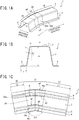
- the press-formed component shape 1 illustrated in FIG. 1 is a hat-shaped cross-sectional shape including a top sheet portion 2 and a vertical wall portion 3 and a flange portion 4 respectively continuous on both sides of a widthwise direction of the top sheet portion 2, and includes, at a certain position along a longitudinal direction of the top sheet portion 2, a curved portion 1A curved in such a manner as to protrude toward one side of the widthwise direction of the top sheet portion 2 as seen in a plan view.
- FIG. 1 is a hat-shaped cross-sectional shape including a top sheet portion 2 and a vertical wall portion 3 and a flange portion 4 respectively continuous on both sides of a widthwise direction of the top sheet portion 2, and includes, at a certain position along a longitudinal direction of the top sheet portion 2, a curved portion 1A curved in such a manner as to protrude toward one side of the widthwise direction of the top sheet portion 2 as seen in a plan view.
- reference sign 2A denotes the top sheet portion at the curved portion 1A.
- Reference sign 3Aa denotes the vertical wall portion on a curved protruding side at the curved portion 1A.
- Reference sign 4Aa denotes the flange portion on the curved protruding side at the curved portion 1A.
- Reference sign 3Ab denotes the vertical wall portion on a curved recessed side at the curved portion 1A.
- Reference sign 4Ab denotes the flange portion on the curved recessed side at the curved portion 1A.
- a metal sheet 10 for use in production of a press-formed component of the present embodiment is particularly suitably effective in cases where the metal sheet 10 is made of a high tensile strength steel material, such as a material having a tensile strength of 590 MPa or more.
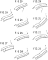
- FIG. 2 illustrates examples of the press-formed component shape 1 that is a subject of the present invention. As illustrated in FIG.
- the press-formed component shape 1 as the subject of the present invention is any press-formed component shape that includes, at a certain position along the longitudinal direction of the top sheet portion 2, the curved portion 1A curved in such a manner as to protrude toward one side of the widthwise direction of the top sheet portion 2 as seen in a plan view.
- the adjacent curved portions 1A may be continuously formed in the plan view, where any linearly extending portion does not have to be present between the adjacent curved portions 1A.
- the press-formed component shape 1 may include a portion curved up and down along the longitudinal direction, as seen in a side view.
- any linear portion 1B does not have to be present between the adjacent curved portions 1A.
- FIG. 1C exemplifies a case where the curved portion 1A is curved in such a manner as to protrude on an upper side of the paper (recessed on a lower side of the paper).
- the curved protruding side is referred to also as curved outer side
- the curved recessed side is referred to also as curved inner side.
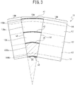
- an example of the metal sheet 10 to be used is a metal sheet 10 blanked into a developed shape of the desired press-formed component shape 1 developed on a plane, as illustrated in FIG. 3 .
- the press-formed component shape 1 includes one curved portion 1A and linear portions 1B on the left and right thereof, so that the developed shape also includes the one curved portion 10A and the linear portions 10B on the left and right thereof.
- the left and right linear portions 10B have a shape developed with dimensions of the press-formed component shape 1.
- the curved portion 10A is developed in such a manner that a line length of a position n3 corresponding to a ridge line m3 (particularly, on the curved protruding side) between the top sheet portion 2 and the vertical wall portion 3 is equal to a line length in the press-formed component shape 1, and, in a plan view, an angle 2 ⁇ formed by the flange portion 4Ab on the curved recessed side of the press-formed component shape 1 is equal to an angle formed by the flange portion 4 on the curved recessed side (an angle formed between the left and right linear portions 1B on the curved inner side) in the developed shape.
- FIG. 1 is an example where the contour of an outer edge m2 on the curved recessed side has a shape with a combination of two straight lines, and thus the developed shape is also illustrated so as to have a line length of a curve n2 formed by two straight lines.
- the contour of the outer edge m2 on the curved recessed side has an arc shape, the contour of the outer edge n2 on the curved recessed side of the developed shape also becomes arc-shaped.
- a length of an outer edge n1 on the curved protruding side of the metal sheet 10 corresponding to a length of an outer edge m1 of the flange portion 4Aa (see FIG. 1 ) on the curved outer side in the press-formed component shape 1 is in a relationship of "line length of m1 ⁇ line length of n1".
- a length of the outer edge n2 on the curved inner side of the metal sheet 10 corresponding to a length of the outer edge m2 of the flange portion 4Ab see FIG.
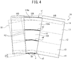
- the metal sheet 10 for press forming is configured to have a sheet-shape as illustrated in FIG. 4 , which sheet-shape is formed by changing the developed shape simply developed as described above to a shape in which a boundary h2 between the curved portion 10A and the linear portion 10B is rotationally displaced in-plane around a rotational center P set within a region (indicated by hatching in FIG. 3 ) positioned on the curved recessed side rather than a position n4 corresponding to a ridge line m4 between the top sheet portion 2 and the vertical wall portion 3 on the curved recessed side.
- the developed shape after the rotational displacement is referred to also as modified developed shape.
- the direction of the in-plane rotational displacement is set to a direction in which, in a fan-shaped region of the curved portion 10A in the developed shape simply developed as described above, the line length of the position n1 that becomes the outer edge of the flange portion 14Aa on the curved protruding side approaches the line length of the outer edge m1 of the flange portion 4Aa on the curved protruding side in the press-formed component shape (i.e., to a direction in which the line length of n1 becomes shorter), and to a direction in which the line length of the outer edge n2 of the position 14Ab to be formed into the flange portion 4Ab on the curved recessed side approaches the line length of the position m2 that becomes the outer edge of the flange portion 4Ab on the curved recessed side in the press-formed component shape (i.e., to a direction in which the line length of n2 becomes longer).
- the amount of rotational displacement is preferably set such that a difference between a line length of an outer edge q1 of a position to be formed into the flange portion 4Aa on the curved protruding side in the modified developed shape and a line length of an outer edge m1 of the flange portion 4Aa on the curved protruding side in the press-formed component is equal to or less than 10% of the outer edge m1 of the flange portion 4Aa on the curved protruding side in the press-formed component shape.
- a projection portion 20 protruding in an out-of-plane direction is formed in regions 12A and 13Aa corresponding to the top sheet portion 2A and the vertical wall portion 3Aa on the curved protruding side in the region corresponding to the curved portion 1A (see FIG. 5 ).
- a difference between a line length of a position q3 corresponding to the ridge line m3 between the top sheet portion 2 and the vertical wall portion 3 on the curved protruding side and the line length of the ridge line m3 between the top sheet portion 2 and the vertical wall portion 3 on the curved protruding side in the press-formed component shape is equal to or less than 10% of the line length of the ridge line m3 between the top sheet portion 2 and the vertical wall portion 3 on the curved protruding side in the press-formed component shape.
- the direction in which the projection portion 20 projects may be downward.
- each linear portion 10B other than the region 10A (the curved portion of the metal sheet 10) corresponding to the curved portion 1A at least one of a position corresponding to a ridge line between the top sheet portion 2 and the vertical wall portion 3 or a position corresponding to a ridge line between the vertical wall portion 3 and the above flange portion 4, the bead shape 21 or a crease shape extending in a direction along the ridge line is provided at least one place (see FIG. 5).
- FIG. 5 illustrates an example provided with the bead shapes 21.
- a broken line indicates a developed shape before the rotation.
- FIG. 4 exemplifies the case where, in the region corresponding to the curved portion 1A, a boundary h1 with the right linear portion 1B is fixed, and the boundary h2 with the left linear portion 1B is rotationally displaced to change the above-mentioned line length.
- the boundaries h1 and h2 on both sides may be respectively rotationally displaced.
- the boundaries h1 and h2 on both sides are respectively rotationally displaced by ⁇ each.
- a curvature radius of the ridge line m3 between the top sheet portion 2 and the vertical wall portion 3 on the curved protruding side is defined as R (mm), a width of the top sheet portion 2 as W (mm), a vertical height of the vertical wall portion 3 as H (mm), an angle formed between a horizontal surface of the top sheet portion 2 and the vertical wall portion 3 as ⁇ (deg), and a width of the flange portion 4 as f (mm).
- the angle ⁇ to be applied to the rotational displacement may be designed so as to satisfy the following expression: 0.9 ⁇ ⁇ ′ ⁇ ⁇ ⁇ 1.1 ⁇ ⁇ ′
- the line length of q1 may be designed so as to satisfy the following expression: 0.9 ⁇ line length of m 1 ⁇ line length of q 1 ⁇ 1.1 ⁇ line length of m 1
- the line length of the position q3 corresponding to the ridge line m3 between the top sheet portion 12 and the vertical wall portion 13Aa on the curved protruding side becomes shorter than the line length of the ridge line m3 in the press-formed component shape 1.
- the projection portion 20 protruding in an out-of-plane direction is formed in the region of a top sheet portion 12A and the vertical wall portion 13Aa on the curved protruding side in the region 10A corresponding to the curved portion 1A.
- the line length of the position q3 corresponding to the ridge line m3 between the top sheet portion 2 and the vertical wall portion 3 on the curved protruding side in the metal sheet 10 is designed so as to approach the line length in the press-formed component shape 1.
- the projection portion 20 is designed such that an increased amount ⁇ L of the line length of the position q3 corresponding to the ridge line m3 between the top sheet portion 12 and the vertical wall portion 13Aa on the curved protruding side in the metal sheet 10 satisfies the following expression: 0.9 ⁇ ⁇ 90 R 90 ⁇ ⁇ ⁇ R ⁇ W sin 90 ⁇ ⁇ sin 90 ⁇ ⁇ ⁇ ⁇ 90 ⁇ ⁇ ⁇ ⁇ ⁇ L ⁇ 1.1 ⁇ ⁇ 90 R 90 ⁇ ⁇ ⁇ R ⁇ W sin 90 ⁇ ⁇ sin 90 ⁇ ⁇ ⁇ ⁇ 90 ⁇ ⁇ ⁇ ⁇ ⁇ ⁇ ⁇ ⁇
- the line length of the position q3 corresponding to the ridge line m3 between the top sheet portion 12 and the vertical wall portion 13Aa on the curved protruding side in the metal sheet 10 approaches the line length of the corresponding ridge line m3 in the press-formed component shape 1. Specifically, it is possible to set to a line length difference of 10% or less.
- the projection portion 20 is designed into a protruding shape such that, regarding an amount of the line length increased in the longitudinal direction by formation of the projection portion, the increased amount at the line length position of the ridge line between the top sheet portion 2 and the vertical wall portion 3 on the curved protruding side in the metal sheet 10 is the largest.
- FIG. 5 it is preferable to form, at least one of positions corresponding to ridge lines of each linear portion 10B, a bead shape 21 extending along the ridge line.
- FIG. 5 is an example where the bead shape 21 is formed at positions corresponding to the ridge lines on both sides of the top sheet portion 2, but the invention is not limited thereto.
- the bead shape 21 may be also formed at positions corresponding to ridge lines between the vertical wall portion 3 and the flange portion 4 or at only some of the ridge lines at the ridge-line positions. Additionally, it is unnecessary to form the bead shape 21 over an entire length of one ridge line, and the bead shape 21 may be intermittently formed along the ridge line.
- the total length of the bead shape 21 is preferably set so as to be equal to or more than 1/3 of the entire length of the corresponding ridge line.
- a crease may be formed.
- the bead shape 21 and a crease may be used in combination such that the bead shape 21 is provided at a part thereof, and the crease is provided at the other part thereof.
- the projection portion forming step is a step of forming the projection portion 20 by stretch forming the metal sheet 10.
- the projection portion 20 may be provided by drawing or stamping. The following description will exemplify formation by drawing.
- the length of the position q3 corresponding to the ridge line m3 of the top sheet portion 2 on the curved protruding side of the metal sheet 10 is designed by rotationally displacing by 2 ⁇ in-plane around the rotational center P. Due to this, the length of the position q3 becomes shorter than the line length of the ridge line m3 of the top sheet portion 2 on the curved protruding side in the press-formed component shape 1. As a result, if press forming is performed as it is, tensile deformation is accordingly applied to the produced press-formed component.
- the projection portion 20 is formed on the metal sheet 10 at the projection portion forming step to secure the line length up to the same amount as the length of the ridge line m3 of the top sheet portion 2 on the curved protruding side in the press-formed component shape 1.
- a drawing die is prepared that includes an upper die formed by a die 30 and a lower die formed by a punch 31 and a blank holder 32, for example, as illustrated in FIG. 6 , and stretch forming for forming the projection portion 20 is performed by the drawing die.
- the die 30 is provided with a recessed portion 30A corresponding to the shape of the projection portion 20 at a portion facing the punch 31.
- the length of the projection portion 20 at the position q3 corresponding to the ridge line m3 is designed so as to be longer by ⁇ L than a length before forming the projection portion 20.
- ⁇ L may be set on the basis of the above description.
- the shape of the projection portion 20 in the present embodiment is designed, for example, as illustrated in FIG. 5 , in such a manner as to project across positions corresponding to the top sheet portion 12A of the curved portion 10A and the vertical wall portion 13Aa on the curved protruding side.
- the shape of the projection portion 20 is preferably designed so as to be a dome-like shape such that a maximum projection height is given at the position q3 where the required line length ⁇ L is secured, and the projection height is gradually reduced toward the widthwise direction of the top sheet portion 2.
- the shape of the projection portion 20 may be another contour shape as long as the line length can be secured.
- the die illustrated in FIG. 6 is set such that, at the projection portion forming step in advance, the bead shape 21 is provided at the positions corresponding to the ridge lines adjacent to the top sheet portion 2 in the press-formed component shape 1, except for the position for forming the projection portion 20.
- the metal sheet 10 provided with the bead shapes 21 With the metal sheet 10 provided with the bead shapes 21, bending forming into the desired press-formed component shape 1 is stabilized.
- FIG. 5 exemplifies the case of provision of the bead shape 21, a crease may be provided instead of the bead shape 21.
- the present embodiment exemplifies the case of use of the metal sheet 10 including the projection portion 20 and the bead shape 21 formed at the projection portion forming step, as the shape of the metal sheet 10 to be formed at a main forming step (see FIG. 5 ).
- the metal sheet 10 without both or one of the projection portion 20 and the bead shape 21, as in FIG. 4 or the like, may be used as the metal sheet 10 for the main forming step, although processing accuracy is slightly reduced.
- Press forming the above-described metal sheet 10 at the main forming step enables the press-formed component shape 1 to be obtained with suppressed cracks, wrinkles, and spring-back.
- a forming step for the purpose of restrike may be added as a step after the main forming step.
- the main forming step is a step of bending the metal sheet 10 to process into the final press-formed component shape 1.
- a bending die to be used at the main forming step includes an upper die 40 and a lower die 44, as illustrated in FIG. 7 .
- the upper die 40 includes bending blades 43 that bend the ridge lines of the component and a pad 41 that presses the top sheet portion 2.
- the lower die 44 includes a punch 45.
- the pad 41 that pressurizes the top sheet portion 2 in the present embodiment is divided into a pad 41a that pressurizes the top sheet portion 12A of the curved portion 10A and a pad 41b that pressurizes top sheet portions of the linear portions 10B other than the curved portion 1A.
- the pad 41b is preferably set so as to pressurize only the top sheet portion of one of the linear portions 1B positioned on both sides of the curved portion 1A therebetween.
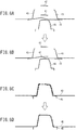
- the metal sheet 10 with the projection portion 20 formed at the projection portion forming step is placed on the punch 45 (see FIG. 8A ).
- the upper die 40 descends.
- the pad 41 and the punch 45 pinches a position 12 corresponding to the top sheet portion of the metal sheet 10 (see FIG. 8B ).
- the bending blades 43 contact with the metal sheet 10 (see FIG. 8C ) and bend ridge lines, and the metal sheet 10 is formed into the press-formed component shape 1 at a bottom dead center (see FIG. 8D ).
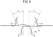
- the bending blades 43 may include a known cam mechanism such that moves from a direction inclined by a certain angle ⁇ with respect to the pressing direction toward the punch 45, as illustrated in FIG. 9 .
- the angle ⁇ is set to an angle inclined by 0 degrees to 90 degrees in directions away from the vertical wall portions 3 with respect to the pressing direction.
- an angle formed by the right linear portion 10B and the left linear portion 10B is relatively larger than a final angle in the press-formed component shape 1 in a plan view due to the rotational displacement.
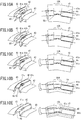
- the bending blades 43 bends the ridge lines to perform bending of the vertical wall portions 3 and the flange portions 4 in the state where the position 12 corresponding to the top sheet portion is partially pinched by the pad 41 and the punch 45, the material is bent while the left linear portion 1B is being rotationally displaced by 2 ⁇ with respect to the right linear portion 1B pinched by the pad 41b, as illustrated in FIG. 10 .
- the curved portion 1A is formed while rotating around the position of the curved recessed side of the top sheet portion 2.
- embossed shapes are provided on the curved recessed side of the top sheet portion 12A in the metal sheet 10 to be subjected to main forming, as illustrated in FIG. 7 . Providing embossed shapes 50 and 51 having unevenness on facing surfaces of the pad 41a and the punch 45 further improves formability.
- the pad 41b that presses the linear portion 10B and the pad 41a that presses the curved portion 10A are structurally independent.
- the setting of the pressurization forces of the pad 41 described above may be made by adjusting an actual pressing force (a cushion force) applied by each of the pads 41a and 41b.
- the above-described setting of the pressurization forces of the pad 41 may be achieved by adjusting stroke of each pad to set such that a height of the pad 41a is relatively higher than a height of the pad 41b during bending.
- FIG. 11 illustrates an example of the shape of a press-formed component after the main forming step.
- Reference sign 9 denotes a provided embossed shape.
- the press-formed component having the hat-shaped cross-sectional shape and including one or more curved portions 1A curved toward one side of the widthwise direction of the top sheet portion 2 in the plan view along the longitudinal direction can be press formed with further reduced forming defects such as cracks, wrinkles, and lowered dimensional accuracy.
- the press-formed component shape 1 including the top sheet portion 2 and the vertical wall portions 3 and the flange portions 4 continuous thereto and including at least one shape curved in the longitudinal direction as seen in a plan view can be formed without any cracks and wrinkles, and furthermore, spring-back due to stress difference in the longitudinal direction between the top sheet portion 2 and the flange portions 4 can be suppressed.
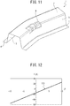
- FIG. 12 illustrates a relationship between ⁇ and calculated value f ( ⁇ ) when ⁇ changes.
- FIG. 12 depicts a case where ⁇ is plotted on the lateral axis and function values of the f( ⁇ ) are plotted on the vertical axis.
- FIG. 12 illustrates a shape of the metal sheet 10 rotationally displaced on the basis of the present invention with respect to the simply-developed developed shape.
- the projection portion 20 was formed on the metal sheet 10 at the projection portion forming step.
- the line length ⁇ L was calculated that was required to be secured at the ridge line m3 of the top sheet portion 2 on the curved protruding side.
- the design method as described above was employed to design the shape of the metal sheet 10 of the present Example, as illustrated in FIG. 13 , and a stretch forming die for use in the projection portion forming step.
- the metal sheet 10 was provided with the bead shape 21 having a height of 3 mm and a width of 5 mm at positions corresponding to ridge lines on both sides of the widthwise direction adjacent to the top sheet portion 12 in the linear portions 10B.
- a blank holding force of 50 ton was set, and the upper die was brought down to a bottom dead center to perform an analysis for forming the metal sheet 10 including the projection portion 20.
- pads 41a and 41b divided into two were used to independently press the curved portion 1A and the region of one of the left and right linear portions 1B other than that in the top sheet portion 12.
- the amounts of stroke and pressure of the pad 41a were 100 mm and 2 ton
- the stroke and pressure of the pad 41b were 125 mm and 10 ton. Note that heights of the pads 41a and 41b at initial positions were made equal.
- FIG. 14 illustrates a die used in the drawing.
- the drawing die includes an upper die formed by a die 61 and a lower die formed by a punch 63 and a blank holder 62 that presses the flange portions 4.
- the blank holding force was set to 50 ton.
- Comparative Example used, as a shape of a metal sheet 60 for press forming, a sheet having the developed shape obtained by simply developing the press-formed component shape 1 (see FIG. 3 ).
- FIG. 15 illustrates a sheet thickness reduction rate distribution at a forming bottom dead center when forming into the desired press-formed component shape 1 was performed by the conventional method. Additionally, FIG. 16 illustrates a sheet thickness reduction rate distribution at a forming bottom dead center when forming into the desired press-formed component shape 1 was performed on the basis of the present invention.
- the press-formed component formed by the method based on the present invention was produced by forming the metal sheet 10 by bending, almost no increase in the sheet thickness was seen on the flange portion 4 on the curved protruding side.
- the material was supplied by rotation of the material, so that almost no tensile deformation was applied, and thus there was no sheet thickness reduction.
- FIG. 17 illustrates a stress distribution (a longitudinal axial force distribution) at a sheet thickness center in the longitudinal direction (x direction) at the forming bottom dead center when the sheet was formed into the press-formed component shape 1 by the conventional method.
- FIG. 18 illustrates a stress distribution (a longitudinal axial force distribution) at a sheet thickness center in the longitudinal direction (x direction) at the forming bottom dead center when the sheet was formed into the press-formed component shape 1 by the method based on the present invention.
- FIG. 19 illustrates a distribution of sheet thickness front-back stress difference in a cross-sectional direction (a direction along the cross section) at the forming bottom dead center when forming into the press-formed component shape 1 was performed by the conventional method.
- FIG. 20 illustrates a distribution of sheet thickness front-back stress difference in the cross-sectional direction (the direction along the cross section) at the forming bottom dead center when forming into the press-formed component shape 1 was performed by the method based on the present invention.
- FIG. 21 illustrates a distribution of deviation amounts from a normal shape after spring-back in the press-formed component shape 1 formed by the conventional method.
- FIG. 22 illustrates a distribution of deviation amounts from a normal shape after spring-back in the press-formed component shape 1 formed by the method based on the present invention.
- the forming method based on the present invention is a forming method that reduces the sheet thickness center stress in the longitudinal direction (x direction) and the sheet thickness front-back stress difference in the widthwise direction that cause the above-mentioned spring-back.
- the forming method has enabled significant suppression of the spring-back, as compared with the conventional drawing method.
Landscapes
- Engineering & Computer Science (AREA)
- Mechanical Engineering (AREA)
- Chemical & Material Sciences (AREA)
- Combustion & Propulsion (AREA)
- Transportation (AREA)
- Shaping Metal By Deep-Drawing, Or The Like (AREA)
- Bending Of Plates, Rods, And Pipes (AREA)
Abstract
Description
- The present invention is a technology relating to production of a press-formed component that has a hat-shaped cross-sectional shape including a vertical wall portion and a flange portion respectively continuous in left and right widthwise directions of a top sheet portion and that has a shape including one or more curved portions curved toward one side of the widthwise directions of the top sheet portion as seen in a plan view along a longitudinal direction of the top sheet portion. In particular, the invention is a technology suitable for production of a press-formed component that serves as a vehicle frame component.
- Vehicle frame components are, for example, configured to have a hat-shaped cross-sectional shape including a vertical wall portion and a flange portion continuous on both sides of a widthwise direction of a top sheet portion and also have a component shape including, at least one part in a longitudinal direction of the top sheet portion, one or more curved portions curved in such a manner as to protrude toward one side of the widthwise direction of the top sheet portion as seen in a plan view. When press forming a metal sheet into a vehicle frame component having such a component shape, a crack or a wrinkle may occur on a part of a formed component, so that a forming defect may occur. Moreover, when the metal sheet is press formed into the component shape as described above, a spring-back or the like exceeding a predetermined amount easily occurs in the formed product after release, which causes a problem such as lowered dimensional accuracy.
- Particularly, in recent vehicle frame components, use of a metal sheet formed by a thin high tensile strength steel sheet has been increasing in order to achieve both vehicle lightweighting and collision safety. However, with increased material strength (tensile strength) of the metal sheet, ductility of the metal sheet decreases, and spring-back becomes large. Due to this, when a high tensile strength steel sheet is simply press formed into a desired component shape, a problem becomes apparent, which is that a crack, a wrinkle, or a spring-back exceeding an acceptable level occurs in the press-formed component.
- For example, when a metal sheet is press formed into a component shape as described above having a shape curved in the widthwise direction of the top sheet portion at a predetermined place along the longitudinal direction in a plan view, a crack due to shortage of material ductility easily occurs at the flange portion on a curved inner side (a curved recessed side) as seen in a plan view. Additionally, at the flange portion on a curved outer side (a curved protruding side) as seen in the plan view, a wrinkle due to material excess easily occurs. Furthermore, due to a stress difference in the longitudinal direction occurring between the top sheet portion and the flange portions in addition to opening of the cross section caused by spring-back, poor dimensional accuracy tends to occur, such as three-dimensional distortion of the produced press-formed component. To cope with phenomena of occurrence of these forming defects, some preventive technologies have conventionally been proposed.
- Regarding a crack on the flange portion on the curved inner side in the press-formed component shape curved in the plan view, for example,
PTL 1 describes a preventive method.PTL 1 proposes use of a metal sheet including a projection portion that protrudes toward a curved recessed side direction with respect to an outer edge portion of a crack risk portion so as to avoid deformation concentration during press forming. - Additionally, regarding a wrinkle at the flange portion on the outer side curved in the plan view, for example,
PTL 2 describes a preventive method. PTL 2 proposes elimination of line length excess by providing a bead shape to a part where material excess occurs so that wrinkles are suppressed. - Furthermore, in
PTL 3 to 5, when press forming into an intermediate formed component curved in the widthwise direction of a top sheet portion along a longitudinal direction at a first forming step, the intermediate formed component is formed to have a shape such that the width of the top sheet portion is different from that in a final product shape, and subsequently, at a second forming step, press forming is performed such that the shape of the intermediate formed component becomes the final product shape.PTL 3 to 5 propose this method to relieve a stress acting as a factor that causes the occurrence of spring-back. -
- PTL 1:
JP Pat. No. 6119848 - PTL 2:
JP Pat. No. 5217928 - PTL 3:
JP Pat. No. 4920649 - PTL 4:
JP Pat. No. 5031702 - PTL 5:
JP Pat. No. 5031703 - However, the method described in
PTL 1 requires, as a step next to a press forming step of press forming into a desired press-formed component shape, a post step of cutting an unnecessary part. - In the method described in
PTL 2, providing the bead shape to eliminate the material excess can significantly change the component shape, so that the bead shape that can be provided is limited. - Additionally, in the method described in
PTL 3 to 5, if a crack or a wrinkle occurs during forming of the intermediate formed component by press forming of the first forming step that is a first step, application to press forming is difficult. Furthermore, in the method described inPTL 3 to 5, when drawing is employed as forming of the first forming step, large warping occurs on the vertical wall portions, which makes it difficult to take countermeasures at the next step and thereafter. - The present invention has been made in view of the above-described problems, and it is an object of the invention to provide a technology capable of further reducing forming defects such as cracks, wrinkles, and lowered dimensional accuracy when producing, by press forming, a press-formed component having a hat-shaped cross-sectional shape and including one or more curved portions curved toward one side of a widthwise direction of a top sheet portion in a plan view along a longitudinal direction.
- The present inventors conducted intensive studies about a press forming method capable of forming, without cracks and wrinkles, a press-formed component shape (a final component shape) that has a hat-shaped cross-sectional shape including a top sheet portion and a vertical wall portion and a flange portion continuous to the top sheet portion and that includes a curved portion at least one or more places in a longitudinal direction of the top sheet portion as seen in a plan view and capable of suppressing spring-back. As a result of the studies, the present inventors obtained a knowledge that excess and shortage of material at the flange portions that becomes a factor causing the occurrence of a crack, a wrinkle, and spring-back can be reduced by forming while rotationally displacing a part of the material when forming the metal sheet into the press-formed component shape. Additionally, the present inventors obtained a knowledge that material shortage at the top sheet portion that becomes a factor causing the occurrence of spring-back can be significantly reduced by previously performing stretch forming at a predetermined place at a pre-step before a step of forming into the press-formed component shape to secure a line length likely to become insufficient.
- The present invention has been made on the basis of such findings.
- Then, to solve the problems, a metal sheet for press forming according to one aspect of the present invention, which is a metal sheet for press forming that is press formed into a press-formed component shape that has a hat-shaped cross-sectional shape including a vertical wall portion and a flange portion on both sides of a widthwise direction of a top sheet portion and that includes, at one or more places along a longitudinal direction of the top sheet portion, a curved portion curved in such a manner as to protrude toward one side of the widthwise direction of the top sheet portion as seen in a plan view, in which, in a developed shape of the press-formed component shape developed on a plane in such a manner that, in a region corresponding to the curved portion, a line length of a position corresponding to a ridge line between the top sheet portion and the vertical wall portion in the press-formed component shape is equal to a line length of the ridge line, a boundary between the region corresponding to the curved portion of the developed shape and an other region is rotationally displaced in-plane around a rotational center set at a position on a curved recessed side rather than a position corresponding to a ridge line between the top sheet portion and the vertical wall portion on the curved recessed side, in a direction in which a line length of an outer edge of a position to be formed into the flange portion on a curved protruding side in the developed shape approaches a line length of an outer edge of the flange portion on the curved protruding side in the press-formed component shape.
- Additionally, a press forming device according to one aspect of the present invention is a press forming device configured to press form a metal sheet for press forming according to the one aspect of the present invention into a press-formed component shape that has a hat-shaped cross-sectional shape including a vertical wall portion and a flange portion on both sides of a widthwise direction of a top sheet portion and that includes, at one or more places along a longitudinal direction of the top sheet portion, a curved portion curved in such a manner as to protrude toward one side of the widthwise direction of the top sheet portion in a plan view, the press forming device including an upper die including a die, a pad, and bending blades and a lower die including a punch facing the pad in a pressing direction, in which the pad is divided into a first pad configured to pressurize the region corresponding to the curved portion in the top sheet portion and a second pad configured to pressurize a region of a linear portion other than the curved portion in the top sheet portion, and in which the bending blades are configured to be capable of bending the vertical wall portions and the flange portions.
- In addition, a method for producing a press-formed component according to one aspect of the present invention includes placing the metal sheet of the one aspect of the present invention on a punch; then causing an upper die to descend toward a lower die to pinch a position of a top sheet portion by a pad of the upper die and the punch; and causing the upper die to further descend to perform bending of vertical wall portions and flange portions by bending blades of the upper die, in which the press-formed component is produced by making a pressurization force applied to the top sheet portion by the pad at a linear portion position other than a curved portion relatively larger than the pressurization force at a curved portion position to perform the bending.
- According to the one aspect of the present invention, there is provided a technology capable of press forming into a press-formed component having a hat-shaped cross-sectional shape and including one or more curved portions curved toward one side of the widthwise direction of a top sheet portion in a plan view along the longitudinal direction of the top sheet portion, can be press formed with further reduced forming defects such as cracks, wrinkles, and lowered dimensional accuracy.
-
-
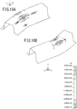
FIG. 1 is a diagram illustrating one example of a press-formed component shape, in whichFIG. 1A is a perspective view,FIG. 1B is a cross-sectional view, andFIG. 1C is a plan view; -
FIG. 2 is a diagram listing examples of a press-formed component shape to which the present invention is applicable; -
FIG. 3 is a diagram illustrating a developed shape of a metal sheet obtained by developing on a plane the press-formed component shape illustrated inFIG. 1 ; -
FIG. 4 is a diagram illustrating an example of a sheet shape (a developed shape after rotational displacement) of the metal sheet (the metal sheet to be press formed) after rotationally displacing a boundary between a region of a curved portion and an other region in the developed shape; -
FIG. 5 is a diagram illustrating an example of the sheet shape of the metal sheet provided with a projection portion and a bead shape; -
FIG. 6 is a diagram describing an example of a die for use in a projection portion forming step of providing the projection portion and the bead shape; -
FIG. 7 is a diagram describing an example of a bending die for use in a main forming step; -
FIG. 8 is a diagram illustrating movement of the bending die in the main forming step; -
FIG. 9 is a diagram exemplifying by arrows an example of directions in which bending blades move during bending at the main forming step; -
FIG. 10 is a diagram illustrating movement of a material at the main forming step; -
FIG. 11 is a perspective view illustrating one embodiment of the press-formed component shape formed by the main forming step; -
FIG. 12 is a diagram illustrating a relationship between β and design variables according to the present invention method in Example, in which the lateral axis represents β and the vertical axis represents f(β); -
FIG. 13 illustrates a metal sheet designed on the basis of the present invention in Example; -
FIG. 14 is a diagram illustrating the structure of a conventional drawing die in Example; -
FIG. 15 is a diagram illustrating sheet thickness reduction rates at a bottom dead center when formed by conventional drawing in Example; -
FIG. 16 is a diagram illustrating sheet thickness reduction rates at a bottom dead center when formed on the basis of the present invention in Example; -
FIG. 17 is a diagram illustrating an axial force distribution in a longitudinal direction at the bottom dead center when formed by the conventional drawing in Example; -
FIG. 18 is a diagram illustrating an axial force distribution in a longitudinal direction at the bottom dead center when formed on the basis of the present invention in Example; -
FIG. 19 is a diagram illustrating a sheet thickness front-back stress difference distribution in a widthwise direction at the bottom dead center when formed by the conventional drawing in Example; -
FIG. 20 is a diagram illustrating a sheet thickness front-back stress difference distribution in a widthwise direction at the bottom dead center when formed on the basis of the present invention in Example; -
FIG. 21 is a diagram illustrating a distribution of deviation amounts from a press-formed component shape after release when formed by the conventional drawing in Example; and -
FIG. 22 is a diagram illustrating a distribution of deviation amounts from a press-formed component shape after release when formed on the basis of the present invention in Example. - Next, embodiments of the present invention will be described with reference to the drawings.
- The following description of the embodiments will be provided by taking, as an example, a case where a metal sheet is press formed into a press-formed
component shape 1 as illustrated inFIG. 1 to produce a final component. The press-formedcomponent shape 1 illustrated inFIG. 1 is a hat-shaped cross-sectional shape including atop sheet portion 2 and avertical wall portion 3 and aflange portion 4 respectively continuous on both sides of a widthwise direction of thetop sheet portion 2, and includes, at a certain position along a longitudinal direction of thetop sheet portion 2, acurved portion 1A curved in such a manner as to protrude toward one side of the widthwise direction of thetop sheet portion 2 as seen in a plan view. InFIG. 1 ,reference sign 2A denotes the top sheet portion at thecurved portion 1A. Reference sign 3Aa denotes the vertical wall portion on a curved protruding side at thecurved portion 1A. Reference sign 4Aa denotes the flange portion on the curved protruding side at thecurved portion 1A. Reference sign 3Ab denotes the vertical wall portion on a curved recessed side at thecurved portion 1A. Reference sign 4Ab denotes the flange portion on the curved recessed side at thecurved portion 1A. - A
metal sheet 10 for use in production of a press-formed component of the present embodiment is particularly suitably effective in cases where themetal sheet 10 is made of a high tensile strength steel material, such as a material having a tensile strength of 590 MPa or more. - However, the present invention is applicable even to production of a press-formed component having a shape including the
curved portion 1A at a plurality of places along the longitudinal direction as seen in a plan view. In the case including thecurved portions 1A of the plurality of places, directions of curves of the adjacentcurved portions 1A may be the same or different, as seen in a plan view.FIG. 2 illustrates examples of the press-formedcomponent shape 1 that is a subject of the present invention. As illustrated inFIG. 2 , the press-formedcomponent shape 1 as the subject of the present invention is any press-formed component shape that includes, at a certain position along the longitudinal direction of thetop sheet portion 2, thecurved portion 1A curved in such a manner as to protrude toward one side of the widthwise direction of thetop sheet portion 2 as seen in a plan view. In the press-formedcomponent shape 1, the adjacentcurved portions 1A may be continuously formed in the plan view, where any linearly extending portion does not have to be present between the adjacentcurved portions 1A. Additionally, the press-formedcomponent shape 1 may include a portion curved up and down along the longitudinal direction, as seen in a side view. In addition, in the press-formedcomponent shape 1, anylinear portion 1B does not have to be present between the adjacentcurved portions 1A. - Herein, in the press-formed
component shape 1 illustrated inFIG. 1, FIG. 1C exemplifies a case where thecurved portion 1A is curved in such a manner as to protrude on an upper side of the paper (recessed on a lower side of the paper). Note that, in the present specification, the curved protruding side is referred to also as curved outer side, and the curved recessed side is referred to also as curved inner side. - When producing a component having the press-formed
component shape 1 illustrated inFIG. 1 by press forming, an example of themetal sheet 10 to be used is ametal sheet 10 blanked into a developed shape of the desired press-formedcomponent shape 1 developed on a plane, as illustrated inFIG. 3 . In the case of the present example, the press-formedcomponent shape 1 includes onecurved portion 1A andlinear portions 1B on the left and right thereof, so that the developed shape also includes the onecurved portion 10A and thelinear portions 10B on the left and right thereof. - In the above developed shape, the left and right
linear portions 10B have a shape developed with dimensions of the press-formedcomponent shape 1. On the other hand, generally, thecurved portion 10A is developed in such a manner that a line length of a position n3 corresponding to a ridge line m3 (particularly, on the curved protruding side) between thetop sheet portion 2 and thevertical wall portion 3 is equal to a line length in the press-formedcomponent shape 1, and, in a plan view, an angle 2α formed by the flange portion 4Ab on the curved recessed side of the press-formedcomponent shape 1 is equal to an angle formed by theflange portion 4 on the curved recessed side (an angle formed between the left and rightlinear portions 1B on the curved inner side) in the developed shape. Note thatFIG. 1 is an example where the contour of an outer edge m2 on the curved recessed side has a shape with a combination of two straight lines, and thus the developed shape is also illustrated so as to have a line length of a curve n2 formed by two straight lines. However, if the contour of the outer edge m2 on the curved recessed side has an arc shape, the contour of the outer edge n2 on the curved recessed side of the developed shape also becomes arc-shaped. - In the
metal sheet 10 having the developed shape as described above, at thecurved portion 10A, a length of an outer edge n1 on the curved protruding side of themetal sheet 10 corresponding to a length of an outer edge m1 of the flange portion 4Aa (seeFIG. 1 ) on the curved outer side in the press-formedcomponent shape 1 is in a relationship of "line length of m1 < line length of n1". Additionally, a length of the outer edge n2 on the curved inner side of themetal sheet 10 corresponding to a length of the outer edge m2 of the flange portion 4Ab (seeFIG. 1 ) on the curved inner side in the press-formedcomponent shape 1 is in a relationship of "line length of m2 > line length of n2". Thus, when themetal sheet 10 having the above-described developed shape (seeFIG. 3 ) is press formed into the press-formedcomponent shape 1 ofFIG. 1 , there is material excess on the curved outer side, causing wrinkles, whereas there is material shortage on the curved inner side, causing cracks. - Accordingly, in the present embodiment, the
metal sheet 10 for press forming is configured to have a sheet-shape as illustrated inFIG. 4 , which sheet-shape is formed by changing the developed shape simply developed as described above to a shape in which a boundary h2 between thecurved portion 10A and thelinear portion 10B is rotationally displaced in-plane around a rotational center P set within a region (indicated by hatching inFIG. 3 ) positioned on the curved recessed side rather than a position n4 corresponding to a ridge line m4 between thetop sheet portion 2 and thevertical wall portion 3 on the curved recessed side. Note that the developed shape after the rotational displacement (the metal sheet having the rotationally displaced shape) is referred to also as modified developed shape. - The direction of the in-plane rotational displacement is set to a direction in which, in a fan-shaped region of the
curved portion 10A in the developed shape simply developed as described above, the line length of the position n1 that becomes the outer edge of the flange portion 14Aa on the curved protruding side approaches the line length of the outer edge m1 of the flange portion 4Aa on the curved protruding side in the press-formed component shape (i.e., to a direction in which the line length of n1 becomes shorter), and to a direction in which the line length of the outer edge n2 of the position 14Ab to be formed into the flange portion 4Ab on the curved recessed side approaches the line length of the position m2 that becomes the outer edge of the flange portion 4Ab on the curved recessed side in the press-formed component shape (i.e., to a direction in which the line length of n2 becomes longer). - Note that, in the example of
FIG. 4 , only the boundary h2 on one side is rotationally displaced. - The amount of rotational displacement is preferably set such that a difference between a line length of an outer edge q1 of a position to be formed into the flange portion 4Aa on the curved protruding side in the modified developed shape and a line length of an outer edge m1 of the flange portion 4Aa on the curved protruding side in the press-formed component is equal to or less than 10% of the outer edge m1 of the flange portion 4Aa on the curved protruding side in the press-formed component shape.
- Furthermore, in the modified developed shape, preferably, a
projection portion 20 protruding in an out-of-plane direction is formed inregions 12A and 13Aa corresponding to thetop sheet portion 2A and the vertical wall portion 3Aa on the curved protruding side in the region corresponding to thecurved portion 1A (seeFIG. 5 ). In this case, it is preferable to set such that with theprojection portion 20, a difference between a line length of a position q3 corresponding to the ridge line m3 between thetop sheet portion 2 and thevertical wall portion 3 on the curved protruding side and the line length of the ridge line m3 between thetop sheet portion 2 and thevertical wall portion 3 on the curved protruding side in the press-formed component shape is equal to or less than 10% of the line length of the ridge line m3 between thetop sheet portion 2 and thevertical wall portion 3 on the curved protruding side in the press-formed component shape. Note that the direction in which theprojection portion 20 projects may be downward. - Additionally, preferably, in the region of each
linear portion 10B other than theregion 10A (the curved portion of the metal sheet 10) corresponding to thecurved portion 1A, at least one of a position corresponding to a ridge line between thetop sheet portion 2 and thevertical wall portion 3 or a position corresponding to a ridge line between thevertical wall portion 3 and theabove flange portion 4, thebead shape 21 or a crease shape extending in a direction along the ridge line is provided at least one place (seeFIG. 5). FIG. 5 illustrates an example provided with the bead shapes 21. - Hereinafter, a description will be given of a specific example regarding the shape of the
metal sheet 10 for press forming of the present embodiment. In other words, the description will be given of an example of design change in the shape of thecurved portion 10A from the simply-developed developed shape to a modified developed shape. - As an example, a case will be described where the above-mentioned rotational center P is set at a center position of the outer edge n2 (see
FIG. 3 ) on the curved recessed side in the developed shape (seeFIG. 4 ). - The shape of the
metal sheet 10 for press is designed so as to be a shape (a modified developed shape) in which the boundary h2 between thecurved portion 10A and thelinear portion 10B is rotationally displaced by 2β (deg) in a direction in which an angle formed by the curved recessed side (an angle formed by theflange portion 4 on the inner side of thecurved portion 1A in the press-formed component shape 1) increases, around the rotational center P that is a center position of the outer edge (an angle of the flange portion 4Ab) on the curved inner side of themetal sheet 10 in the simply-developed press-formedcomponent shape 1 so that the length of the outer edge portion q1 on the curved protruding side of themetal sheet 10 satisfies "line length of m1 = line length of q1". Herein, inFIG. 4 , a broken line indicates a developed shape before the rotation. - Herein, when rotationally displaced in-plane around the above rotational center P in the direction in which the line length of the outer edge on the curved protruding side of the
metal sheet 10 becomes shorter, the line length of the outer edge portion n2 on the curved recessed side changes to become longer.FIG. 4 exemplifies the case where, in the region corresponding to thecurved portion 1A, a boundary h1 with the rightlinear portion 1B is fixed, and the boundary h2 with the leftlinear portion 1B is rotationally displaced to change the above-mentioned line length. The boundaries h1 and h2 on both sides may be respectively rotationally displaced. For example, the boundaries h1 and h2 on both sides are respectively rotationally displaced by β each. - Additionally, the position of the rotational center P may be adjusted so as to satisfy "line length of m2 = line length of q2".
- In this example, from a geometrical relationship between the sheet shape (the modified developed shape) of the
metal sheet 10 rotationally displaced as above and the press-formedcomponent shape 1, the value of 2β that satisfies "line length of m1 = line length of q1" is calculated. - A specific calculation method is as follows:
Herein, as inFIG. 1 , a curvature radius of the ridge line m3 between thetop sheet portion 2 and thevertical wall portion 3 on the curved protruding side is defined as R (mm), a width of thetop sheet portion 2 as W (mm), a vertical height of thevertical wall portion 3 as H (mm), an angle formed between a horizontal surface of thetop sheet portion 2 and thevertical wall portion 3 as θ (deg), and a width of theflange portion 4 as f (mm). - In this case, in an expression of f(β) in the following expressions, when β satisfies f(β) = 0, "the line length of m1 = line length of q1" is valid.


- However, when a margin is provided, and β satisfying f(β) = 0 is β', the angle β to be applied to the rotational displacement may be designed so as to satisfy the following expression:

- Additionally, the line length of q1 may be designed so as to satisfy the following expression:

- In the sheet shape after the modification (the modified developed shape), the line length of the position q3 corresponding to the ridge line m3 between the
top sheet portion 12 and the vertical wall portion 13Aa on the curved protruding side becomes shorter than the line length of the ridge line m3 in the press-formedcomponent shape 1. - Considering this, in the above sheet shape (the modified developed shape), preferably, the
projection portion 20 protruding in an out-of-plane direction is formed in the region of atop sheet portion 12A and the vertical wall portion 13Aa on the curved protruding side in theregion 10A corresponding to thecurved portion 1A. By doing this, the line length of the position q3 corresponding to the ridge line m3 between thetop sheet portion 2 and thevertical wall portion 3 on the curved protruding side in themetal sheet 10 is designed so as to approach the line length in the press-formedcomponent shape 1. - In the case of the present example, the
projection portion 20 is designed such that an increased amount ΔL of the line length of the position q3 corresponding to the ridge line m3 between thetop sheet portion 12 and the vertical wall portion 13Aa on the curved protruding side in themetal sheet 10 satisfies the following expression:
- By designing so as to satisfy the expression, the line length of the position q3 corresponding to the ridge line m3 between the
top sheet portion 12 and the vertical wall portion 13Aa on the curved protruding side in themetal sheet 10 approaches the line length of the corresponding ridge line m3 in the press-formedcomponent shape 1. Specifically, it is possible to set to a line length difference of 10% or less. - Note that, preferably, the
projection portion 20 is designed into a protruding shape such that, regarding an amount of the line length increased in the longitudinal direction by formation of the projection portion, the increased amount at the line length position of the ridge line between thetop sheet portion 2 and thevertical wall portion 3 on the curved protruding side in themetal sheet 10 is the largest. - In addition, as illustrated in
FIG. 5 , it is preferable to form, at least one of positions corresponding to ridge lines of eachlinear portion 10B, abead shape 21 extending along the ridge line.FIG. 5 is an example where thebead shape 21 is formed at positions corresponding to the ridge lines on both sides of thetop sheet portion 2, but the invention is not limited thereto. Thebead shape 21 may be also formed at positions corresponding to ridge lines between thevertical wall portion 3 and theflange portion 4 or at only some of the ridge lines at the ridge-line positions. Additionally, it is unnecessary to form thebead shape 21 over an entire length of one ridge line, and thebead shape 21 may be intermittently formed along the ridge line. When forming thebead shape 21 at a part of the entire length of the ridge line, for example, the total length of thebead shape 21 is preferably set so as to be equal to or more than 1/3 of the entire length of the corresponding ridge line. Furthermore, instead of thebead shape 21, a crease may be formed. Furthermore, thebead shape 21 and a crease may be used in combination such that thebead shape 21 is provided at a part thereof, and the crease is provided at the other part thereof. - Next will be a description of a method for forming the
projection portion 20 by press forming the flat sheet-shapedmetal sheet 10. The projection portion forming step is a step of forming theprojection portion 20 by stretch forming themetal sheet 10. Theprojection portion 20 may be provided by drawing or stamping. The following description will exemplify formation by drawing. - Herein, in the sheet shape as in
FIG. 4 obtained by changing the shape of thecurved portion 10A in the developed shape as described above, the length of the position q3 corresponding to the ridge line m3 of thetop sheet portion 2 on the curved protruding side of themetal sheet 10 is designed by rotationally displacing by 2β in-plane around the rotational center P. Due to this, the length of the position q3 becomes shorter than the line length of the ridge line m3 of thetop sheet portion 2 on the curved protruding side in the press-formedcomponent shape 1. As a result, if press forming is performed as it is, tensile deformation is accordingly applied to the produced press-formed component. The applied tensile deformation becomes a factor that causes spring-back. Thus, preferably, theprojection portion 20 is formed on themetal sheet 10 at the projection portion forming step to secure the line length up to the same amount as the length of the ridge line m3 of thetop sheet portion 2 on the curved protruding side in the press-formedcomponent shape 1. - From such a viewpoint, at the projection portion forming step of the present embodiment, a drawing die is prepared that includes an upper die formed by a
die 30 and a lower die formed by apunch 31 and ablank holder 32, for example, as illustrated inFIG. 6 , and stretch forming for forming theprojection portion 20 is performed by the drawing die. Thedie 30 is provided with a recessedportion 30A corresponding to the shape of theprojection portion 20 at a portion facing thepunch 31. - The length of the
projection portion 20 at the position q3 corresponding to the ridge line m3 is designed so as to be longer by ΔL than a length before forming theprojection portion 20. Herein, ΔL may be set on the basis of the above description. - The shape of the
projection portion 20 in the present embodiment is designed, for example, as illustrated inFIG. 5 , in such a manner as to project across positions corresponding to thetop sheet portion 12A of thecurved portion 10A and the vertical wall portion 13Aa on the curved protruding side. Additionally, the shape of theprojection portion 20 is preferably designed so as to be a dome-like shape such that a maximum projection height is given at the position q3 where the required line length ΔL is secured, and the projection height is gradually reduced toward the widthwise direction of thetop sheet portion 2. However, the shape of theprojection portion 20 may be another contour shape as long as the line length can be secured. - Furthermore, the die illustrated in
FIG. 6 is set such that, at the projection portion forming step in advance, thebead shape 21 is provided at the positions corresponding to the ridge lines adjacent to thetop sheet portion 2 in the press-formedcomponent shape 1, except for the position for forming theprojection portion 20. With themetal sheet 10 provided with the bead shapes 21, bending forming into the desired press-formedcomponent shape 1 is stabilized. AlthoughFIG. 5 exemplifies the case of provision of thebead shape 21, a crease may be provided instead of thebead shape 21. In addition, there may be provided a combination of thebead shape 21 provided at some of the ridge line positions and a crease or the like provided at other ridge line positions. - The present embodiment exemplifies the case of use of the
metal sheet 10 including theprojection portion 20 and thebead shape 21 formed at the projection portion forming step, as the shape of themetal sheet 10 to be formed at a main forming step (seeFIG. 5 ). However, themetal sheet 10 without both or one of theprojection portion 20 and thebead shape 21, as inFIG. 4 or the like, may be used as themetal sheet 10 for the main forming step, although processing accuracy is slightly reduced. - Press forming the above-described
metal sheet 10 at the main forming step enables the press-formedcomponent shape 1 to be obtained with suppressed cracks, wrinkles, and spring-back. When it is desired to further improve dimensional accuracy or desired to provide a required shape to the component, a forming step for the purpose of restrike may be added as a step after the main forming step. - The main forming step is a step of bending the
metal sheet 10 to process into the final press-formedcomponent shape 1. - A bending die to be used at the main forming step includes an
upper die 40 and alower die 44, as illustrated inFIG. 7 . Theupper die 40 includes bendingblades 43 that bend the ridge lines of the component and apad 41 that presses thetop sheet portion 2. Thelower die 44 includes apunch 45. - The
pad 41 that pressurizes thetop sheet portion 2 in the present embodiment is divided into apad 41a that pressurizes thetop sheet portion 12A of thecurved portion 10A and apad 41b that pressurizes top sheet portions of thelinear portions 10B other than thecurved portion 1A. Thepad 41b is preferably set so as to pressurize only the top sheet portion of one of thelinear portions 1B positioned on both sides of thecurved portion 1A therebetween. - Next, an example of movement of the bending die at the main forming step will be illustrated with reference to
FIG. 8 . - The
metal sheet 10 with theprojection portion 20 formed at the projection portion forming step is placed on the punch 45 (seeFIG. 8A ). - In this state, the
upper die 40 descends. When theupper die 40 descends, first, thepad 41 and thepunch 45 pinches aposition 12 corresponding to the top sheet portion of the metal sheet 10 (seeFIG. 8B ). When theupper die 40 further descends, thebending blades 43 contact with the metal sheet 10 (seeFIG. 8C ) and bend ridge lines, and themetal sheet 10 is formed into the press-formedcomponent shape 1 at a bottom dead center (seeFIG. 8D ). - In this case, when a sheet thickness direction (a perpendicular direction) of the
position 12 corresponding to the top sheet portion is assumed as a pressing direction, thebending blades 43 may include a known cam mechanism such that moves from a direction inclined by a certain angle θ with respect to the pressing direction toward thepunch 45, as illustrated inFIG. 9 . - Finally, the
upper die 40 is raised and released to complete the forming. - Preferably, the angle θ is set to an angle inclined by 0 degrees to 90 degrees in directions away from the
vertical wall portions 3 with respect to the pressing direction. - Movement of the material at the main forming step will be described with reference to
FIG. 10 . - In the sheet shape as in
FIG. 4 obtained by rotationally displacing in-plane the position of thecurved portion 10A in the developed shape, an angle formed by the rightlinear portion 10B and the leftlinear portion 10B is relatively larger than a final angle in the press-formedcomponent shape 1 in a plan view due to the rotational displacement. - Thus, when the
upper die 40 descends, and thebending blades 43 bends the ridge lines to perform bending of thevertical wall portions 3 and theflange portions 4 in the state where theposition 12 corresponding to the top sheet portion is partially pinched by thepad 41 and thepunch 45, the material is bent while the leftlinear portion 1B is being rotationally displaced by 2β with respect to the rightlinear portion 1B pinched by thepad 41b, as illustrated inFIG. 10 . In other words, thecurved portion 1A is formed while rotating around the position of the curved recessed side of thetop sheet portion 2. - At this time, the material gathers to the
top sheet portion 2 and thevertical wall portion 3 on the rotational center P side in the rotational displacement, and compressive deformation is applied. Considering this, embossed shapes are provided on the curved recessed side of thetop sheet portion 12A in themetal sheet 10 to be subjected to main forming, as illustrated inFIG. 7 . Providingembossed shapes pad 41a and thepunch 45 further improves formability. - Additionally, to facilitate the material at the position corresponding to the
curved portion 1A as seen in a plan view to be rotationally displaced relatively with respect to the rightlinear portion 10B abutted with thepad 41b, thepad 41b that presses thelinear portion 10B and thepad 41a that presses thecurved portion 10A are structurally independent. In this case, to further facilitate the rotational displacement of the material at the position corresponding to thecurved portion 10A, it is preferable to set a relationship between pressurization force of thepad 41a that presses thecurved portion 10A and pressurization force of thepad 41b that presses the rightlinear portion 10B to the following relationship: - Pad pressurization force by
pad 41a < pad pressurization force bypad 41b - The setting of the pressurization forces of the
pad 41 described above may be made by adjusting an actual pressing force (a cushion force) applied by each of thepads pad 41 may be achieved by adjusting stroke of each pad to set such that a height of thepad 41a is relatively higher than a height of thepad 41b during bending. -
FIG. 11 illustrates an example of the shape of a press-formed component after the main forming step.Reference sign 9 denotes a provided embossed shape. -
- (1) The following sheet shape is employed for the
metal sheet 10 for press forming that is press-formed into the press-formedcomponent shape 1 that has the hat-shaped cross-sectional shape including thevertical wall portion 3 and theflange portion 4 on both sides of the widthwise direction of thetop sheet portion 2 and that includes, at one or more places along the longitudinal direction, thecurved portion 1A curved in such a manner as to protrude toward one side of the widthwise direction of thetop sheet portion 2 in the plan view.
Specifically, themetal sheet 10 for press forming has a sheet shape obtained by modifying the developed shape of the press-formedcomponent shape 1 simply developed on a plane in such a manner that, in theregion 10A corresponding to thecurved portion 1A, the line length of the position n3 corresponding to the ridge line m3 between thetop sheet portion 2 and thevertical wall portion 3 in the press-formedcomponent shape 1 is equal to the line length of the ridge line m3 into the shape such that, in theregion 10A corresponding to thecurved portion 1A, the boundary h2 between theregion 10A corresponding to thecurved portion 1A and theother region 10B is rotationally displaced in-plane around the rotational center P set at a position on the curved recessed side rather than the position q4 corresponding to the ridge line between thetop sheet portion 2 and the vertical wall portion 3Ab on the curved recessed side, in the direction in which the line length of the position q1 that becomes the outer edge m1 of the flange portion 4Aa on the curved protruding side approaches the line length of the outer edge m1 of the flange portion 4Aa on the curved protruding side in the press-formed component shape.
With use of theabove metal sheet 10, the line lengths of theflange portions 4 on the curved protruding side and the curved recessed side in thecurved portion 1A approach the line lengths in the press-formed component. As a result, the press-formed component having a hat-shaped cross-sectional shape and including one or morecurved portions 1A curved toward one side of the widthwise direction of thetop sheet portion 2 in the plan view along the longitudinal direction can be press formed with further reduced forming defects such as cracks, wrinkles, and lowered dimensional accuracy. - (2) In this case, preferably, the difference between the line length of the position q1 that becomes the outer edge of the
flange portion 4 on the curved protruding side in the modified developed shape and the line length of the outer edge m1 of theflange portion 4 on the curved protruding side in the press-formed component is set to equal to or less than 10% of the line length of the outer edge m1 of theflange portion 4 on the curved protruding side in the press-formed component shape.
This structure can further ensure that press forming is performed with further reduced forming defects such as cracks, wrinkles, and lowered dimensional accuracy. - (3) In the
metal sheet 10, preferably, theprojection portion 20 protruding in an out-of-plane direction is formed in the regions corresponding to thetop sheet portion 2 and thevertical wall portion 3 on the curved protruding side in the region corresponding to thecurved portion 1A. In this case, it is preferable that with theprojection portion 20, the difference between the line length of the position q3 corresponding to the ridge line m3 between thetop sheet portion 2 and thevertical wall portion 3 on the curved protruding side and the line length of the ridge line m3 between thetop sheet portion 2 and thevertical wall portion 3 on the curved protruding side in the press-formed component shape is set to equal to or less than 10% of the line length of the ridge line m3 between thetop sheet portion 2 and thevertical wall portion 3 on the curved protruding side in the press-formed component shape.
With this structure, the reduction in the line length of the position q3 corresponding to the ridge line m3 between thetop sheet portion 2 and thevertical wall portion 3 on the curved protruding side due to the modification of the developed shape described above is eliminated, and the difference between the line lengths becomes small. As a result, it can be further ensured that press forming is performed with further reduced forming defects such as cracks, wrinkles, and lowered dimensional accuracy. - (4) Preferably, in the region of each
linear portion 10B other than the region corresponding to thecurved portion 10A includes, at least one ridge line position of the positions that become the ridge lines, thebead shape 21 or a crease shape extending in the direction along the ridge line is provided at least one place.
With this structure, when bending themetal sheet 10 having the above-described structure, it can be further ensured that bending at the ridge line positions can be performed, thereby enabling more accurate press forming. - (5) The present embodiment is significantly effective when the
metal sheet 10 for press forming is made of a material having a tensile strength of 590 MPa or more. - (6) Forming of the
projection portion 20 onto themetal sheet 10 for press forming may be performed by, for example, drawing or stamping.
Employing drawing or stamping can ensure formation of theprojection portion 20. - (7) The press forming device for press forming the
metal sheet 10 into the desired press-formedcomponent shape 1 is configured to include theupper die 40 including thedie 42, the pad, and thebending blades 43 and the lower die including thepunch 45 facing the pad in the pressing direction, in which thepad 41 is divided into thepad 41a that pressurizes the region corresponding to thecurved portion 1A in thetop sheet portion 2 and thepad 41b that pressurizes the region of thelinear portions 1B other than thecurved portion 1A in thetop sheet portion 2, and in which thebending blades 43 are configured to perform bending of thevertical wall portions 3 and theflange portions 4. It is preferable to set such that when, in the bending, the pressurization force applied to thetop sheet portion 2 by thepad 41a is P1 and the pressurization force applied to thetop sheet portion 2 by thepad 41b is P2, P1 < P2 holds.
With this structure, restraint of thecurved portion 1A by thepad 41 is set relatively weak, as a result of which the material at the position of thecurved portion 10A is relatively easily moved. This can further ensure that themetal sheet 10 can be bent into the desired press-formedcomponent shape 1 while allowing the rotational displacement at the position of thecurved portion 10A. - (8) In the press forming device of the present embodiment, when the sheet thickness direction of the
top sheet portion 2 is set as a pressing direction, it is preferable to set such that at least one of thebending blades 43 moves at an angle of from 0 degrees to 90 degrees with respect to the pressing direction, and preferably at an angle of from 0 degrees to 45 degrees with respect to the pressing direction to perform bending of thevertical wall portion 3 and theflange portion 4. More preferred is an angle of from 5 degrees to 40 degrees. - (9) In the press forming device, preferably, the
pad 41a is formed with the embossedshape 50 on a surface abutting the region of the curved recessed side in thetop sheet portion 2, and the embossedshape 51 also is formed at a position facing an embossed shape-formed region in thepunch 45. - (10) In the method for producing a press-formed component of the present embodiment, after the
metal sheet 10 is placed on thepunch 45, theupper die 40 is caused to descend to bring theupper die 40 close to thelower die 44, then the position of thetop sheet portion 2 is pinched by thepad 41 of theupper die 40 and thepunch 45, and theupper die 40 is caused to further descend. By doing this, thevertical wall portions 3 and theflange portions 4 are bent by thebending blades 43 of theupper die 40. Regarding the pressurization force applied to thetop sheet portion 12 by thepad 41 during bending, the pressurization force at thelinear portions 10B other than thecurved portion 10A is set to be relatively larger than the pressurization force at the position of thecurved portion 1A. - With this structure, the press-formed component having the hat-shaped cross-sectional shape and including one or more
curved portions 1A curved toward one side of the widthwise direction of thetop sheet portion 2 in the plan view along the longitudinal direction can be press formed with further reduced forming defects such as cracks, wrinkles, and lowered dimensional accuracy. - As above, according to the present embodiment, the press-formed
component shape 1 including thetop sheet portion 2 and thevertical wall portions 3 and theflange portions 4 continuous thereto and including at least one shape curved in the longitudinal direction as seen in a plan view can be formed without any cracks and wrinkles, and furthermore, spring-back due to stress difference in the longitudinal direction between thetop sheet portion 2 and theflange portions 4 can be suppressed. - Next, Examples based on the present invention will be described.
- Assuming a cold-rolled steel sheet having a tensile strength of 1180 MPa (sheet thickness: 1.4 mm), press forming analysis of a press-formed component having the press-formed
component shape 1 as illustrated inFIG. 1 was performed. In the present Example, shape parameters in thecurved portion 1A that define the press-formedcomponent shape 1 were set as follows:
<Cross-Sectional Shape Parameters>
Top sheet portion 2's width W: 100 mm
Vertical wall height H: 100 mmm
Vertical wall angle θ: 10 deg
Flange length f: 30 mm
<Bending Parameters in Plan View>
Bending angle α: 80 deg
Top sheet portion 2's perimeter radius R: 500 mm - In designing the shape of the
metal sheet 10 for use in the above press-formedcomponent shape 1, a center position of the position n2 corresponding to the outer edge m2 of the flange portion 4Ab on the curved recessed side was set as the rotational center P in the developed shape simply developed as inFIG. 3 , and the angle 2β for rotating around the angle of the flange portion 14Ab on the curved recessed side was calculated by the above-mentioned expression. -
FIG. 12 illustrates a relationship between β and calculated value f (β) when β changes.FIG. 12 depicts a case where β is plotted on the lateral axis and function values of the f(β) are plotted on the vertical axis. - In
FIG. 12 , 2β when f(β) = 0 in rotational displacement is an optimum rotational angle. Then, in the present Example, when β = 3.5, f(β) = 0. Therefore, the rotational angle 2β is 7 deg.FIG. 13 illustrates a shape of themetal sheet 10 rotationally displaced on the basis of the present invention with respect to the simply-developed developed shape. - Additionally, in the present Example, the
projection portion 20 was formed on themetal sheet 10 at the projection portion forming step. - First, the line length ΔL was calculated that was required to be secured at the ridge line m3 of the
top sheet portion 2 on the curved protruding side. The parameters of thecomponent shape 1 and the value of β previously calculated were substituted in the above-mentioned expression to result in ΔL = 13 mm. - The design method as described above was employed to design the shape of the
metal sheet 10 of the present Example, as illustrated inFIG. 13 , and a stretch forming die for use in the projection portion forming step. - Furthermore, in the present Example, to stably perform forming at the main forming step, the
metal sheet 10 was provided with thebead shape 21 having a height of 3 mm and a width of 5 mm at positions corresponding to ridge lines on both sides of the widthwise direction adjacent to thetop sheet portion 12 in thelinear portions 10B. At the projection portion forming step, a blank holding force of 50 ton was set, and the upper die was brought down to a bottom dead center to perform an analysis for forming themetal sheet 10 including theprojection portion 20. - Next, with use of the bending die illustrated in
FIG. 7 , analysis was made for the main forming step of forming themetal sheet 10 including theprojection portion 20 into the desired press-formedcomponent 1. At the main forming step, thebending blades 43 bending formation positions of the ridge lines moved at an angle inclined by 30 degrees with respect to the pressing direction, and formed using the cam mechanism for bending thevertical wall portion 3 and theflange portions 4. - Additionally, as pads for pinching the
top sheet portion 12,pads curved portion 1A and the region of one of the left and rightlinear portions 1B other than that in thetop sheet portion 12. In this case, the amounts of stroke and pressure of thepad 41a were 100 mm and 2 ton, and the stroke and pressure of thepad 41b were 125 mm and 10 ton. Note that heights of thepads - In addition, as Comparative Example relative to Example of the present invention, an analysis using drawing that has been conventionally performed was also performed together.
FIG. 14 illustrates a die used in the drawing. The drawing die includes an upper die formed by adie 61 and a lower die formed by apunch 63 and ablank holder 62 that presses theflange portions 4. The blank holding force was set to 50 ton. - Furthermore, Comparative Example used, as a shape of a
metal sheet 60 for press forming, a sheet having the developed shape obtained by simply developing the press-formed component shape 1 (seeFIG. 3 ). -
FIG. 15 illustrates a sheet thickness reduction rate distribution at a forming bottom dead center when forming into the desired press-formedcomponent shape 1 was performed by the conventional method. Additionally,FIG. 16 illustrates a sheet thickness reduction rate distribution at a forming bottom dead center when forming into the desired press-formedcomponent shape 1 was performed on the basis of the present invention. - In the press-formed component formed by the conventional drawing, since the
flange portions 4 were pinched by thedie 42 and the blank holder, it was possible to form without any increase in the sheet thickness on theflange portion 4 of the outer side curved in the longitudinal direction. - In addition, although the press-formed component formed by the method based on the present invention was produced by forming the
metal sheet 10 by bending, almost no increase in the sheet thickness was seen on theflange portion 4 on the curved protruding side. - However, at the
flange portion 4 on the curved recessed side formed by the conventional drawing, tensile deformation was applied at a flange end due to material shortage, so that sheet thickness reduction was seen. - On the other hand, at the flange on the curved recessed side in the method based on the present invention, the material was supplied by rotation of the material, so that almost no tensile deformation was applied, and thus there was no sheet thickness reduction.
-
FIG. 17 illustrates a stress distribution (a longitudinal axial force distribution) at a sheet thickness center in the longitudinal direction (x direction) at the forming bottom dead center when the sheet was formed into the press-formedcomponent shape 1 by the conventional method. Additionally,FIG. 18 illustrates a stress distribution (a longitudinal axial force distribution) at a sheet thickness center in the longitudinal direction (x direction) at the forming bottom dead center when the sheet was formed into the press-formedcomponent shape 1 by the method based on the present invention. - In addition,
FIG. 19 illustrates a distribution of sheet thickness front-back stress difference in a cross-sectional direction (a direction along the cross section) at the forming bottom dead center when forming into the press-formedcomponent shape 1 was performed by the conventional method.FIG. 20 illustrates a distribution of sheet thickness front-back stress difference in the cross-sectional direction (the direction along the cross section) at the forming bottom dead center when forming into the press-formedcomponent shape 1 was performed by the method based on the present invention. - In the press-formed component formed by the conventional drawing, tensile stress was applied to the
top sheet portion 2 on the curved protruding side, and compressive stress to theflange portion 4 thereon, whereas compressive stress was applied to thetop sheet portion 2 on the curved recessed side, and tensile stress to theflange portion 4 thereon. In this case, a stress difference occurring between thetop sheet portion 2 and theflange portions 4 becomes a source that generates a spring-back moment that causes three-dimensional distortion of the press-formed component. - On the other hand, in the method based on the present invention, tensile deformation was applied to the flange on the curved protruding side, and compressive stress was reduced. Furthermore, on the contrary, the material gathered to the
flange portion 4 on the curved recessed side, so that tensile deformation was reduced. In addition, since stretch forming was performed on thetop sheet portion 2 on the curved protruding side at the projection portion forming step to compensate for the expected shortage of the material in advance, whereby tensile stress was reduced. At thetop sheet portion 2 on the curved recessed side, the material gathers, and compressive stress is applied. Thus, thebead shape 21 was provided as in the present Example to suppress the occurrence of compressive stress. - Next, when looking at the front-back stress difference distribution in the sheet thickness direction of the cross-sectional direction of the component formed by the conventional drawing, a large sheet thickness front-back stress difference was seen on the
vertical wall portions 3 of the component. The front-back stress difference of thevertical wall portions 3 becomes a stress that causes thevertical wall portions 3 to spring back so as to warp. - On the other hand, when checking the distribution of sheet thickness front-back stress difference in the widthwise direction of the component formed by the method based on the present invention, it can be seen that the front-back stress difference distribution in the sheet thickness direction of the
vertical wall portions 3 seen in the conventional method has hardly occurred. This is due to the fact that because of the bending-oriented forming performed at the main forming step, the material has not been subjected to bending-unbending deformation that generates a stress that causes the occurrence of vertical wall warp. - Next,
FIG. 21 illustrates a distribution of deviation amounts from a normal shape after spring-back in the press-formedcomponent shape 1 formed by the conventional method.FIG. 22 illustrates a distribution of deviation amounts from a normal shape after spring-back in the press-formedcomponent shape 1 formed by the method based on the present invention. - As described above, in the conventional method, there was a difference in the sheet thickness center stress in the longitudinal direction (x direction) between the
top sheet portion 2 and theflange portions 4 of thecurved portion 1A in the longitudinal direction, whereby three-dimensional spring-back occurred, and distortion was observable. Additionally, at thevertical wall portions 3 as well, the spring-back moment that causes the occurrence of warp caused large warping of thevertical wall portions 3, whereby the cross section was significantly deviated in an opening direction. - On the other hand, the forming method based on the present invention is a forming method that reduces the sheet thickness center stress in the longitudinal direction (x direction) and the sheet thickness front-back stress difference in the widthwise direction that cause the above-mentioned spring-back. Thus, the forming method has enabled significant suppression of the spring-back, as compared with the conventional drawing method.
- Herein, this application claims the benefit of priority of Japanese Patent Application No.
2018-034569 (filled on Feb. 28, 2018 -
- 1:
- Press-formed component shape
- 1A:
- Curved portion
- 1B:
- Linear portion
- 2, 2A:
- Top sheet portion
- 3, 3Aa, 3Ab:
- Vertical wall portion
- 4, 4Aa, 4Ab:
- Flange portion
- 10:
- Metal sheet
- 10A:
- Curved portion
- 10B:
- Linear portion
- 12, 12A:
- Top sheet portion
- 13Aa:
- Vertical wall portion
- 14Aa, 14Ab:
- Flange portion
- 20:
- Projection portion
- 21:
- Bead shape
- 30:
- Die
- 30A:
- Recessed portion
- 31:
- Punch
- 40:
- Upper die
- 41:
- Pad
- 41a:
- Pad (first pad)
- 41b:
- Pad (second pad)
- 42:
- Die
- 43:
- Bending blade
- 44:
- Lower die
- 44:
- Punch
- 50, 51:
- Embossed shape
- h1, h2:
- Boundary
- 2α:
- Angle
- P:
- Rotational center
Claims (10)
- A metal sheet for press forming to be press formed into a press-formed component shape that has a hat-shaped cross-sectional shape including a vertical wall portion and a flange portion on both sides of a widthwise direction of a top sheet portion and that includes, at one or more places along a longitudinal direction of the top sheet portion, a curved portion curved in such a manner as to protrude toward one side of the widthwise direction of the top sheet portion as seen in a plan view,
wherein, in a developed shape of the press-formed component shape developed on a plane in such a manner that a line length of a position corresponding to a line length of a ridge line between the top sheet portion and the vertical wall portion in the press-formed component shape is equal to a line length of a position corresponding to the ridge line in a region corresponding to the curved portion, a boundary between the region corresponding to the curved portion of the developed shape and an other region is rotationally displaced in-plane around a rotational center set at a position on a curved recessed side rather than a position corresponding to a ridge line between the top sheet portion and the vertical wall portion on the curved recessed side, in a direction in which a line length of an outer edge of a position to be formed into the flange portion on a curved protruding side in the developed shape approaches a line length of an outer edge of the flange portion on the curved protruding side in the press-formed component shape. - The metal sheet for press forming according to claim 1, wherein a difference between the line length of the outer edge of the position to be formed into the flange portion on the curved protruding side in the metal sheet having the rotationally displaced shape and the line length of the outer edge of the flange portion on the curved protruding side in the press-formed component shape is set to equal to or less than 10% of the line length of the outer edge of the flange portion on the curved protruding side in the press-formed component shape.
- The metal sheet for press forming according to claim 1 or 2, comprising a projection portion protruding in an out-of-plane direction in regions corresponding to the top sheet portion and the vertical wall portion on the curved protruding side in the region corresponding to the curved portion, wherein with the projection portion, a difference between a line length of a position corresponding to a ridge line between the top sheet portion and the vertical wall portion on the curved protruding side in the metal sheet having the rotationally displaced shape and a line length of a ridge line between the top sheet portion and the vertical wall portion on the curved protruding side in the press-formed component shape is set to equal to or less than 10% of the line length of the ridge line between the top sheet portion and the vertical wall portion on the curved protruding side in the press-formed component shape.
- The metal sheet for press forming according to any one of claims 1 to 3, wherein, in a region of a linear portion other than the region corresponding to the curved portion, at least one position of positions corresponding to ridge lines between the top sheet portion and the vertical wall portions and positions corresponding to ridge lines between the vertical wall portions and the flange portions, there is provided at least one bead shape or crease shape extending in a direction along the corresponding ridge line.
- The metal sheet for press forming according to any one of claims 1 to 4, the metal sheet being made of a material having a tensile strength of 590 MPa or more.
- A press forming device configured to press form the metal sheet according to any one of claims 1 to 5 into a press-formed component shape that has a hat-shaped cross-sectional shape including a vertical wall portion and a flange portion on both side of a widthwise direction of a top sheet portion and that includes, at one or more places along a longitudinal direction of the top sheet portion, a curved portion curved in such a manner as to protrude toward one side of the widthwise direction of the top sheet portion in a plan view, the press forming device comprising an upper die including a die, a pad, and bending blades and a lower die including a punch facing the pad in a pressing direction, wherein the pad is divided into a first pad configured to pressurize the region corresponding to the curved portion in the top sheet portion and a second pad configured to pressurize a region of a linear portion other than the curved portion in the top sheet portion, and wherein the bending blades are configured to be capable of bending the vertical wall portions and the flange portions.
- The press forming device according to claim 6, wherein when, in the bending, a pressurization force applied to the top sheet portion by the first pad is P1 and a pressurization force applied to the top sheet portion by the second pad is P2, P1 < P2 holds.
- The press forming device according to claim 6 or 7, wherein when a sheet thickness direction of the top sheet portion is set as a pressing direction, at least one of the bending blades is configured to move at an angle of from 0 degrees to 90 degrees with respect to the pressing direction to perform bending of the vertical wall portion and the flange portion.
- The press forming device according to any one of claims 6 to 8, wherein the first pad and a portion of the punch facing the first pad are formed with an embossed shape on surfaces that abut a region on the curved recessed side of the top sheet portion of the curved portion.
- A method for producing a press-formed component comprising: placing the metal sheet according to any one of claims 1 to 5 on a punch; then causing an upper die to descend toward a lower die to pinch a position of a top sheet portion by a pad of the upper die and the punch; and causing the upper die to further descend to perform bending of vertical wall portions and flange portions by bending blades of the upper die, wherein the press-formed component is produced by making a pressurization force applied to the top sheet portion by the pad at a linear portion position other than the curved portion relatively larger than the pressurization force at a curved portion position to perform the bending.
Applications Claiming Priority (2)
| Application Number | Priority Date | Filing Date | Title |
|---|---|---|---|
| JP2018034569 | 2018-02-28 | ||
| PCT/JP2019/006551 WO2019167791A1 (en) | 2018-02-28 | 2019-02-21 | Metal plate for press molding, press molding device, and production method for pressed component |
Publications (3)
| Publication Number | Publication Date |
|---|---|
| EP3760330A1 true EP3760330A1 (en) | 2021-01-06 |
| EP3760330A4 EP3760330A4 (en) | 2021-04-14 |
| EP3760330B1 EP3760330B1 (en) | 2025-09-03 |
Family
ID=67805769
Family Applications (1)
| Application Number | Title | Priority Date | Filing Date |
|---|---|---|---|
| EP19761706.1A Active EP3760330B1 (en) | 2018-02-28 | 2019-02-21 | Metal plate for press molding, press molding device, and production method for pressed component |
Country Status (7)
| Country | Link |
|---|---|
| US (1) | US11383286B2 (en) |
| EP (1) | EP3760330B1 (en) |
| JP (1) | JP6590129B1 (en) |
| KR (1) | KR102339921B1 (en) |
| CN (1) | CN111867747B (en) |
| MX (1) | MX2020008961A (en) |
| WO (1) | WO2019167791A1 (en) |
Families Citing this family (11)
| Publication number | Priority date | Publication date | Assignee | Title |
|---|---|---|---|---|
| CN110795803B (en) * | 2019-11-10 | 2023-09-29 | 中国航发南方工业有限公司 | Extrusion molding blade |
| CN113118315A (en) * | 2019-12-30 | 2021-07-16 | 上海强精金属制品有限公司 | Mould of washing machine front frame plate |
| JP7243670B2 (en) * | 2020-04-16 | 2023-03-22 | Jfeスチール株式会社 | METHOD FOR MANUFACTURING PRESS PARTS, AND METAL PLATE |
| JP7335198B2 (en) * | 2020-04-20 | 2023-08-29 | 豊田鉄工株式会社 | Press molding method for long shape parts, and vehicle pillar member molded by the same molding method |
| JP7335197B2 (en) * | 2020-04-20 | 2023-08-29 | 豊田鉄工株式会社 | Press molding method for long shape parts, and vehicle pillar member molded by the same molding method |
| JP7156340B2 (en) * | 2020-07-08 | 2022-10-19 | Jfeスチール株式会社 | Metal plate bending method |
| JP7587944B2 (en) * | 2020-09-03 | 2024-11-21 | プレス工業株式会社 | Vehicle body frame member and method for manufacturing vehicle body frame member |
| JP7647714B2 (en) * | 2022-02-10 | 2025-03-18 | Jfeスチール株式会社 | Press molding method and manufacturing method of press molded product |
| JP7854972B2 (en) * | 2023-08-23 | 2026-05-07 | 日本製鉄株式会社 | Press forming method |
| CN120189048B (en) * | 2025-05-26 | 2025-08-12 | 湖南省华芯医疗器械有限公司 | Bendable tube, insertion portion, and endoscope |
| CN120438486B (en) * | 2025-07-01 | 2025-10-28 | 聚变新能(安徽)有限公司 | Vacuum chamber shell cover processing die, method for preparing vacuum chamber shell cover and vacuum chamber shell cover |
Family Cites Families (36)
| Publication number | Priority date | Publication date | Assignee | Title |
|---|---|---|---|---|
| JPS4920649B1 (en) | 1969-08-08 | 1974-05-27 | ||
| JPS5031702B1 (en) | 1971-05-08 | 1975-10-14 | ||
| JPS5031703B2 (en) | 1972-02-23 | 1975-10-14 | ||
| JPS5217928B2 (en) | 1973-04-19 | 1977-05-18 | ||
| JPS585523A (en) | 1981-06-30 | 1983-01-12 | Matsushita Electric Ind Co Ltd | Hydrostatic fluid slide device |
| JPH0531703A (en) | 1991-02-21 | 1993-02-09 | Keigo Murase | Automatic setworks for ripsaw |
| JP2602136B2 (en) | 1991-07-29 | 1997-04-23 | 武司 野末 | Long material feeding device |
| JPH05217928A (en) | 1991-11-29 | 1993-08-27 | Nec Corp | Vertical-type heat treating apparatus |
| JP2777763B2 (en) | 1992-09-30 | 1998-07-23 | 株式会社 セガ・エンタープライゼス | Control key device |
| JP4123021B2 (en) * | 2003-03-17 | 2008-07-23 | 三菱自動車工業株式会社 | Car side members |
| JP4359264B2 (en) * | 2005-06-03 | 2009-11-04 | 本田技研工業株式会社 | Car seat mounting structure |
| JP2008200709A (en) | 2007-02-20 | 2008-09-04 | Nissan Motor Co Ltd | Press molded product manufacturing apparatus, press molded product manufacturing method, and press molded product |
| JP5031702B2 (en) | 2008-09-12 | 2012-09-26 | 新日本製鐵株式会社 | Multi-stage press forming method with excellent shape freezing |
| JP4920649B2 (en) * | 2008-09-12 | 2012-04-18 | 新日本製鐵株式会社 | Multi-stage press forming method with excellent shape freezing |
| JP5031703B2 (en) | 2008-09-12 | 2012-09-26 | 新日本製鐵株式会社 | Multi-stage press forming method with excellent shape freezing |
| JP5217928B2 (en) | 2008-11-12 | 2013-06-19 | 新日鐵住金株式会社 | Press working method and press molded body |
| WO2012108282A1 (en) * | 2011-02-09 | 2012-08-16 | 本田技研工業株式会社 | Structure for front side frames of automobile |
| KR101701082B1 (en) * | 2013-01-07 | 2017-02-13 | 신닛테츠스미킨 카부시키카이샤 | Method and device for manufacturing press component |
| BR112015016037A2 (en) * | 2013-01-16 | 2017-07-11 | Nippon Steel & Sumitomo Metal Corp | pressing forming method |
| WO2014185428A1 (en) * | 2013-05-13 | 2014-11-20 | 新日鐵住金株式会社 | Blank, molded plate, method of manufacturing press-molded product and press-molded product |
| WO2015002077A1 (en) * | 2013-07-03 | 2015-01-08 | 新日鐵住金株式会社 | Press molding device and press molding method |
| JP5761275B2 (en) | 2013-08-26 | 2015-08-12 | Jfeスチール株式会社 | Polygonal closed cross-section structural part manufacturing method having bent shape and polygonal closed cross-section structural part manufactured by the method |
| JP5924331B2 (en) * | 2013-11-25 | 2016-05-25 | トヨタ自動車株式会社 | Lower body structure |
| JP6083390B2 (en) * | 2014-01-10 | 2017-02-22 | Jfeスチール株式会社 | Press forming method |
| JP5954380B2 (en) * | 2014-08-26 | 2016-07-20 | Jfeスチール株式会社 | Press molding method and manufacturing method of press molded parts |
| KR20170080681A (en) * | 2014-11-12 | 2017-07-10 | 신닛테츠스미킨 카부시키카이샤 | Manufacturing method and manufacturing device for press-molded article |
| JP5987934B2 (en) * | 2015-02-17 | 2016-09-07 | Jfeスチール株式会社 | Press molding method, press mold |
| US10213819B2 (en) | 2015-02-27 | 2019-02-26 | Sango Co., Ltd. | Press forming method |
| JP5987942B1 (en) | 2015-03-18 | 2016-09-07 | Jfeスチール株式会社 | Press mold |
| US10603707B2 (en) | 2015-03-31 | 2020-03-31 | Jfe Steel Corporation | Press-forming method, method of manufacturing component with the press-forming method and component manufactured with the press-forming method |
| KR101932878B1 (en) | 2015-05-11 | 2018-12-27 | 신닛테츠스미킨 카부시키카이샤 | Press forming apparatus and press forming method |
| US11020785B2 (en) | 2015-07-06 | 2021-06-01 | Nippon Steel Corporation | Method and apparatus for manufacturing press component |
| JP6672933B2 (en) * | 2016-03-24 | 2020-03-25 | 日本製鉄株式会社 | Automotive structural member, manufacturing method thereof, and mold |
| US11358203B2 (en) | 2016-04-04 | 2022-06-14 | Nippon Steel Corporation | Method for producing press-formed product |
| JP6819141B2 (en) | 2016-08-30 | 2021-01-27 | いすゞ自動車株式会社 | Air guide structure of radiator |
| JP6547772B2 (en) * | 2017-01-24 | 2019-07-24 | トヨタ自動車株式会社 | Vehicle floor structure |
-
2019
- 2019-02-21 WO PCT/JP2019/006551 patent/WO2019167791A1/en not_active Ceased
- 2019-02-21 JP JP2019530230A patent/JP6590129B1/en active Active
- 2019-02-21 CN CN201980013220.9A patent/CN111867747B/en active Active
- 2019-02-21 US US16/970,467 patent/US11383286B2/en active Active
- 2019-02-21 KR KR1020207024097A patent/KR102339921B1/en active Active
- 2019-02-21 EP EP19761706.1A patent/EP3760330B1/en active Active
- 2019-02-21 MX MX2020008961A patent/MX2020008961A/en unknown
Also Published As
| Publication number | Publication date |
|---|---|
| CN111867747A (en) | 2020-10-30 |
| KR102339921B1 (en) | 2021-12-15 |
| EP3760330A4 (en) | 2021-04-14 |
| KR20200108069A (en) | 2020-09-16 |
| MX2020008961A (en) | 2020-10-05 |
| JPWO2019167791A1 (en) | 2020-04-16 |
| US20210114075A1 (en) | 2021-04-22 |
| WO2019167791A1 (en) | 2019-09-06 |
| CN111867747B (en) | 2022-05-13 |
| JP6590129B1 (en) | 2019-10-16 |
| EP3760330B1 (en) | 2025-09-03 |
| US11383286B2 (en) | 2022-07-12 |
Similar Documents
| Publication | Publication Date | Title |
|---|---|---|
| EP3760330B1 (en) | Metal plate for press molding, press molding device, and production method for pressed component | |
| EP3760332B1 (en) | Production method for pressed components, press molding device, and metal plate for press molding | |
| CN111727089B (en) | Method for manufacturing press-molded member, press-molding device, and metal plate for press-molding | |
| CN112154036B (en) | Method for manufacturing stamped member | |
| AU2011255898B2 (en) | Method for press-forming l-shaped components | |
| CN109952165B (en) | Method and apparatus for manufacturing press-formed article | |
| CA3018484A1 (en) | Method for producing press-formed product | |
| EP3031544B1 (en) | Press-molded product, method for producing press-molded product, and device for producing press-molded product | |
| EP3272437B1 (en) | Press-forming method and press-forming tool | |
| CN110709181A (en) | Manufacturing method of press-molded product and press production line | |
| EP3909697B1 (en) | Press-forming method, method for manufacturing press-molded article | |
| CN115666809A (en) | Press forming method | |
| EP4137245B1 (en) | Press-forming mold and press-forming method | |
| JP2017042773A (en) | Press molding method | |
| JP6319382B2 (en) | Manufacturing method of stretch flange molded parts | |
| JP6319383B2 (en) | Manufacturing method of stretch flange molded parts | |
| JP2021062381A (en) | Manufacturing method for automobile panel | |
| EP3778057A1 (en) | Rigidity improvement method for press-molded article, press-molding die, press-molded article, and production method for press-molded article | |
| JP2003311339A (en) | Press molded article, method and apparatus for producing press molded article | |
| JP7341840B2 (en) | Automotive panel manufacturing method | |
| JP2011073050A (en) | Method for forming bent member, bent member, and method for manufacturing the same, |
Legal Events
| Date | Code | Title | Description |
|---|---|---|---|
| STAA | Information on the status of an ep patent application or granted ep patent |
Free format text: STATUS: THE INTERNATIONAL PUBLICATION HAS BEEN MADE |
|
| PUAI | Public reference made under article 153(3) epc to a published international application that has entered the european phase |
Free format text: ORIGINAL CODE: 0009012 |
|
| STAA | Information on the status of an ep patent application or granted ep patent |
Free format text: STATUS: REQUEST FOR EXAMINATION WAS MADE |
|
| 17P | Request for examination filed |
Effective date: 20200826 |
|
| AK | Designated contracting states |
Kind code of ref document: A1 Designated state(s): AL AT BE BG CH CY CZ DE DK EE ES FI FR GB GR HR HU IE IS IT LI LT LU LV MC MK MT NL NO PL PT RO RS SE SI SK SM TR |
|
| AX | Request for extension of the european patent |
Extension state: BA ME |
|
| A4 | Supplementary search report drawn up and despatched |
Effective date: 20210312 |
|
| RIC1 | Information provided on ipc code assigned before grant |
Ipc: B21D 22/20 20060101AFI20210305BHEP Ipc: B21D 5/01 20060101ALI20210305BHEP Ipc: B21D 19/08 20060101ALI20210305BHEP Ipc: B21D 22/02 20060101ALI20210305BHEP Ipc: B21D 22/26 20060101ALI20210305BHEP Ipc: B21D 24/00 20060101ALI20210305BHEP Ipc: B21D 22/21 20060101ALI20210305BHEP Ipc: B21D 5/06 20060101ALI20210305BHEP |
|
| DAV | Request for validation of the european patent (deleted) | ||
| DAX | Request for extension of the european patent (deleted) | ||
| STAA | Information on the status of an ep patent application or granted ep patent |
Free format text: STATUS: EXAMINATION IS IN PROGRESS |
|
| 17Q | First examination report despatched |
Effective date: 20230201 |
|
| GRAP | Despatch of communication of intention to grant a patent |
Free format text: ORIGINAL CODE: EPIDOSNIGR1 |
|
| STAA | Information on the status of an ep patent application or granted ep patent |
Free format text: STATUS: GRANT OF PATENT IS INTENDED |
|
| INTG | Intention to grant announced |
Effective date: 20250424 |
|
| RIN1 | Information on inventor provided before grant (corrected) |
Inventor name: YAMASAKI, YUJI Inventor name: SHINMIYA, TOYOHISA Inventor name: MIYAKE, HIROTO |
|
| GRAS | Grant fee paid |
Free format text: ORIGINAL CODE: EPIDOSNIGR3 |
|
| GRAA | (expected) grant |
Free format text: ORIGINAL CODE: 0009210 |
|
| STAA | Information on the status of an ep patent application or granted ep patent |
Free format text: STATUS: THE PATENT HAS BEEN GRANTED |
|
| AK | Designated contracting states |
Kind code of ref document: B1 Designated state(s): AL AT BE BG CH CY CZ DE DK EE ES FI FR GB GR HR HU IE IS IT LI LT LU LV MC MK MT NL NO PL PT RO RS SE SI SK SM TR |
|
| REG | Reference to a national code |
Ref country code: CH Ref legal event code: EP |
|
| REG | Reference to a national code |
Ref country code: DE Ref legal event code: R096 Ref document number: 602019075168 Country of ref document: DE |
|
| REG | Reference to a national code |
Ref country code: IE Ref legal event code: FG4D |
|
| REG | Reference to a national code |
Ref country code: NL Ref legal event code: MP Effective date: 20250903 |
|
| PG25 | Lapsed in a contracting state [announced via postgrant information from national office to epo] |
Ref country code: NO Free format text: LAPSE BECAUSE OF FAILURE TO SUBMIT A TRANSLATION OF THE DESCRIPTION OR TO PAY THE FEE WITHIN THE PRESCRIBED TIME-LIMIT Effective date: 20251203 |
|
| REG | Reference to a national code |
Ref country code: LT Ref legal event code: MG9D |
|
| PG25 | Lapsed in a contracting state [announced via postgrant information from national office to epo] |
Ref country code: FI Free format text: LAPSE BECAUSE OF FAILURE TO SUBMIT A TRANSLATION OF THE DESCRIPTION OR TO PAY THE FEE WITHIN THE PRESCRIBED TIME-LIMIT Effective date: 20250903 |
|
| PG25 | Lapsed in a contracting state [announced via postgrant information from national office to epo] |
Ref country code: HR Free format text: LAPSE BECAUSE OF FAILURE TO SUBMIT A TRANSLATION OF THE DESCRIPTION OR TO PAY THE FEE WITHIN THE PRESCRIBED TIME-LIMIT Effective date: 20250903 |
|
| PG25 | Lapsed in a contracting state [announced via postgrant information from national office to epo] |
Ref country code: GR Free format text: LAPSE BECAUSE OF FAILURE TO SUBMIT A TRANSLATION OF THE DESCRIPTION OR TO PAY THE FEE WITHIN THE PRESCRIBED TIME-LIMIT Effective date: 20251204 |
|
| PG25 | Lapsed in a contracting state [announced via postgrant information from national office to epo] |
Ref country code: SE Free format text: LAPSE BECAUSE OF FAILURE TO SUBMIT A TRANSLATION OF THE DESCRIPTION OR TO PAY THE FEE WITHIN THE PRESCRIBED TIME-LIMIT Effective date: 20250903 |
|
| PG25 | Lapsed in a contracting state [announced via postgrant information from national office to epo] |
Ref country code: LV Free format text: LAPSE BECAUSE OF FAILURE TO SUBMIT A TRANSLATION OF THE DESCRIPTION OR TO PAY THE FEE WITHIN THE PRESCRIBED TIME-LIMIT Effective date: 20250903 |
|
| PG25 | Lapsed in a contracting state [announced via postgrant information from national office to epo] |
Ref country code: PL Free format text: LAPSE BECAUSE OF FAILURE TO SUBMIT A TRANSLATION OF THE DESCRIPTION OR TO PAY THE FEE WITHIN THE PRESCRIBED TIME-LIMIT Effective date: 20250903 Ref country code: BG Free format text: LAPSE BECAUSE OF FAILURE TO SUBMIT A TRANSLATION OF THE DESCRIPTION OR TO PAY THE FEE WITHIN THE PRESCRIBED TIME-LIMIT Effective date: 20250903 |
|
| PG25 | Lapsed in a contracting state [announced via postgrant information from national office to epo] |
Ref country code: RS Free format text: LAPSE BECAUSE OF FAILURE TO SUBMIT A TRANSLATION OF THE DESCRIPTION OR TO PAY THE FEE WITHIN THE PRESCRIBED TIME-LIMIT Effective date: 20251203 |
|
| PG25 | Lapsed in a contracting state [announced via postgrant information from national office to epo] |
Ref country code: ES Free format text: LAPSE BECAUSE OF FAILURE TO SUBMIT A TRANSLATION OF THE DESCRIPTION OR TO PAY THE FEE WITHIN THE PRESCRIBED TIME-LIMIT Effective date: 20250903 |
|
| REG | Reference to a national code |
Ref country code: AT Ref legal event code: MK05 Ref document number: 1832409 Country of ref document: AT Kind code of ref document: T Effective date: 20250903 |
|
| PG25 | Lapsed in a contracting state [announced via postgrant information from national office to epo] |
Ref country code: NL Free format text: LAPSE BECAUSE OF FAILURE TO SUBMIT A TRANSLATION OF THE DESCRIPTION OR TO PAY THE FEE WITHIN THE PRESCRIBED TIME-LIMIT Effective date: 20250903 |
|
| PG25 | Lapsed in a contracting state [announced via postgrant information from national office to epo] |
Ref country code: SM Free format text: LAPSE BECAUSE OF FAILURE TO SUBMIT A TRANSLATION OF THE DESCRIPTION OR TO PAY THE FEE WITHIN THE PRESCRIBED TIME-LIMIT Effective date: 20250903 |
|
| PGFP | Annual fee paid to national office [announced via postgrant information from national office to epo] |
Ref country code: DE Payment date: 20260225 Year of fee payment: 8 |
|
| PG25 | Lapsed in a contracting state [announced via postgrant information from national office to epo] |
Ref country code: AT Free format text: LAPSE BECAUSE OF FAILURE TO SUBMIT A TRANSLATION OF THE DESCRIPTION OR TO PAY THE FEE WITHIN THE PRESCRIBED TIME-LIMIT Effective date: 20250903 |
|
| PG25 | Lapsed in a contracting state [announced via postgrant information from national office to epo] |
Ref country code: IT Free format text: LAPSE BECAUSE OF FAILURE TO SUBMIT A TRANSLATION OF THE DESCRIPTION OR TO PAY THE FEE WITHIN THE PRESCRIBED TIME-LIMIT Effective date: 20250903 |
|
| PG25 | Lapsed in a contracting state [announced via postgrant information from national office to epo] |
Ref country code: IS Free format text: LAPSE BECAUSE OF FAILURE TO SUBMIT A TRANSLATION OF THE DESCRIPTION OR TO PAY THE FEE WITHIN THE PRESCRIBED TIME-LIMIT Effective date: 20260103 |
|
| PGFP | Annual fee paid to national office [announced via postgrant information from national office to epo] |
Ref country code: FR Payment date: 20260225 Year of fee payment: 8 |
|
| PG25 | Lapsed in a contracting state [announced via postgrant information from national office to epo] |
Ref country code: PT Free format text: LAPSE BECAUSE OF FAILURE TO SUBMIT A TRANSLATION OF THE DESCRIPTION OR TO PAY THE FEE WITHIN THE PRESCRIBED TIME-LIMIT Effective date: 20260105 Ref country code: CZ Free format text: LAPSE BECAUSE OF FAILURE TO SUBMIT A TRANSLATION OF THE DESCRIPTION OR TO PAY THE FEE WITHIN THE PRESCRIBED TIME-LIMIT Effective date: 20250903 |
|
| PG25 | Lapsed in a contracting state [announced via postgrant information from national office to epo] |
Ref country code: SK Free format text: LAPSE BECAUSE OF FAILURE TO SUBMIT A TRANSLATION OF THE DESCRIPTION OR TO PAY THE FEE WITHIN THE PRESCRIBED TIME-LIMIT Effective date: 20250903 Ref country code: EE Free format text: LAPSE BECAUSE OF FAILURE TO SUBMIT A TRANSLATION OF THE DESCRIPTION OR TO PAY THE FEE WITHIN THE PRESCRIBED TIME-LIMIT Effective date: 20250903 |