JP5924331B2 - Lower body structure - Google Patents
Lower body structure Download PDFInfo
- Publication number
- JP5924331B2 JP5924331B2 JP2013243338A JP2013243338A JP5924331B2 JP 5924331 B2 JP5924331 B2 JP 5924331B2 JP 2013243338 A JP2013243338 A JP 2013243338A JP 2013243338 A JP2013243338 A JP 2013243338A JP 5924331 B2 JP5924331 B2 JP 5924331B2
- Authority
- JP
- Japan
- Prior art keywords
- cross member
- cross
- vehicle body
- vehicle
- width direction
- Prior art date
- Legal status (The legal status is an assumption and is not a legal conclusion. Google has not performed a legal analysis and makes no representation as to the accuracy of the status listed.)
- Expired - Fee Related
Links
- 230000002787 reinforcement Effects 0.000 claims description 30
- 238000003466 welding Methods 0.000 description 16
- 238000005452 bending Methods 0.000 description 6
- 230000005540 biological transmission Effects 0.000 description 1
- 238000003780 insertion Methods 0.000 description 1
- 230000037431 insertion Effects 0.000 description 1
- 238000005192 partition Methods 0.000 description 1
- 230000000630 rising effect Effects 0.000 description 1
Images


Classifications
-
- B—PERFORMING OPERATIONS; TRANSPORTING
- B62—LAND VEHICLES FOR TRAVELLING OTHERWISE THAN ON RAILS
- B62D—MOTOR VEHICLES; TRAILERS
- B62D25/00—Superstructure or monocoque structure sub-units; Parts or details thereof not otherwise provided for
- B62D25/20—Floors or bottom sub-units
- B62D25/2009—Floors or bottom sub-units in connection with other superstructure subunits
- B62D25/2036—Floors or bottom sub-units in connection with other superstructure subunits the subunits being side panels, sills or pillars
-
- B—PERFORMING OPERATIONS; TRANSPORTING
- B62—LAND VEHICLES FOR TRAVELLING OTHERWISE THAN ON RAILS
- B62D—MOTOR VEHICLES; TRAILERS
- B62D25/00—Superstructure or monocoque structure sub-units; Parts or details thereof not otherwise provided for
- B62D25/08—Front or rear portions
- B62D25/14—Dashboards as superstructure sub-units
- B62D25/145—Dashboards as superstructure sub-units having a crossbeam incorporated therein
-
- B—PERFORMING OPERATIONS; TRANSPORTING
- B62—LAND VEHICLES FOR TRAVELLING OTHERWISE THAN ON RAILS
- B62D—MOTOR VEHICLES; TRAILERS
- B62D25/00—Superstructure or monocoque structure sub-units; Parts or details thereof not otherwise provided for
- B62D25/20—Floors or bottom sub-units
- B62D25/2009—Floors or bottom sub-units in connection with other superstructure subunits
- B62D25/2018—Floors or bottom sub-units in connection with other superstructure subunits the subunits being front structures
Landscapes
- Engineering & Computer Science (AREA)
- Chemical & Material Sciences (AREA)
- Combustion & Propulsion (AREA)
- Transportation (AREA)
- Mechanical Engineering (AREA)
- Body Structure For Vehicles (AREA)
Description
本発明は、車体下部構造に関する。 The present invention relates to a vehicle body lower structure.
ダッシュパネルに閉断面構造のダッシュクロスメンバが設けられ、そのダッシュクロスメンバがフロントピラーに結合された車体前部構造は、従来から提案されている(例えば、特許文献1参照)。 A vehicle body front structure in which a dash cross member having a closed cross-sectional structure is provided on a dash panel and the dash cross member is coupled to a front pillar has been conventionally proposed (see, for example, Patent Document 1).
しかしながら、車両の衝突時にダッシュクロスメンバに入力された荷重を効率よく分散させるための構造には、改善の余地がある。 However, there is room for improvement in the structure for efficiently distributing the load input to the dash cross member at the time of a vehicle collision.
そこで、本発明は、ダッシュパネル側に配置されるクロスメンバに入力された荷重を効率よく分散させられる車体下部構造を得ることを目的とする。 Therefore, an object of the present invention is to obtain a vehicle body lower structure capable of efficiently dispersing a load input to a cross member arranged on the dash panel side.
上記の目的を達成するために、本発明に係る請求項1に記載の車体下部構造は、フロアパネルの車幅方向外側で車体前後方向に延在されたロッカと、ダッシュパネルの下側で車幅方向に延在されるとともに車体上方側へ凸となる断面ハット型形状に形成され、車幅方向外側端部が前記ロッカに結合された第1クロスメンバと、前記第1クロスメンバの車体前方側で車幅方向に延在されるとともに車体上方側へ凸となる断面ハット型形状に形成された第2クロスメンバと、車体上方側へ凸となる断面ハット型形状に形成されて前記第1クロスメンバと前記第2クロスメンバとを連結するとともに、前記ダッシュパネル又は前記フロアパネルとで閉断面構造を構成する連結部材と、を備えたことを特徴としている。 In order to achieve the above object, the vehicle body lower part structure according to claim 1 of the present invention includes a rocker extending in the vehicle longitudinal direction outside the floor panel in the vehicle width direction, and a vehicle under the dash panel. It is formed in the cross-sectional hat shape that is convex to the extended Rutotomoni vehicle upper side in the width direction, a first cross member in the vehicle width direction outside end portion is coupled to the rocker body in front of the first cross member a second cross member formed on the cross-sectional hat shape that is convex to the extended Rutotomoni vehicle upper side in the vehicle width direction at a side, cross-sectional hat-shape formed the first that is convex to the upper side of the vehicle body side The cross member and the second cross member are connected to each other, and a connecting member that forms a closed cross-sectional structure with the dash panel or the floor panel is provided.
請求項1に記載の発明によれば、車幅方向に延在する第1クロスメンバと第2クロスメンバとが、閉断面構造を構成する連結部材によって連結され、第1クロスメンバの車幅方向外側端部が、ロッカに結合されている。したがって、微小ラップ衝突時やオフセット衝突時に、前輪を介してロッカへ入力された衝突荷重は、ロッカだけではなく、第1クロスメンバへも伝達される。そして、第1クロスメンバへ伝達された衝突荷重は、連結部材を介して第2クロスメンバへも伝達される。つまり、第1クロスメンバに入力された衝突荷重が効率よく分散される。 According to the first aspect of the present invention, the first cross member and the second cross member extending in the vehicle width direction are connected by the connecting member that forms the closed cross-sectional structure, and the first cross member is in the vehicle width direction. The outer end is coupled to the rocker. Therefore, the collision load input to the rocker via the front wheel at the time of a minute lap collision or offset collision is transmitted not only to the rocker but also to the first cross member. The collision load transmitted to the first cross member is also transmitted to the second cross member via the connecting member. That is, the collision load input to the first cross member is efficiently dispersed.
また、請求項2に記載の車体下部構造は、請求項1に記載の車体下部構造であって、前記連結部材は、車体前後方向に延在されていることを特徴としている。 A vehicle body lower structure according to a second aspect is the vehicle body lower structure according to the first aspect, wherein the connecting member extends in the vehicle longitudinal direction.
請求項2に記載の発明によれば、連結部材が、車体前後方向に延在されている。したがって、第2クロスメンバに入力された衝突荷重が、第1クロスメンバへ効率よく伝達される。 According to invention of Claim 2, the connection member is extended in the vehicle body front-back direction. Therefore, the collision load input to the second cross member is efficiently transmitted to the first cross member.
また、請求項3に記載の車体下部構造は、請求項1又は請求項2に記載の車体下部構造であって、車体前後方向に延在され、前記フロアパネルとで閉断面構造を構成するフロアリインフォースメントを備え、前記連結部材は、前記フロアリインフォースメントの一部を構成することを特徴としている。 The vehicle body lower structure according to claim 3 is the vehicle body lower structure according to claim 1 or 2, and extends in the vehicle body front-rear direction and forms a closed cross-sectional structure with the floor panel. Reinforcement is provided, and the connecting member constitutes a part of the floor reinforcement.
請求項3に記載の発明によれば、連結部材が、フロアパネルとで閉断面構造を構成するフロアリインフォースメントの一部を構成する。したがって、第2クロスメンバに入力された衝突荷重は、連結部材を介してフロアリインフォースメントへも伝達される。つまり、第2クロスメンバに入力された衝突荷重が効率よく分散される。 According to invention of Claim 3, a connection member comprises a part of floor reinforcement which comprises a closed cross-section structure with a floor panel. Therefore, the collision load input to the second cross member is also transmitted to the floor reinforcement via the connecting member. That is, the collision load input to the second cross member is efficiently dispersed.
また、請求項4に記載の車体下部構造は、請求項1〜請求項3の何れか1項に記載の車体下部構造であって、前記第1クロスメンバ及び前記第2クロスメンバは、それぞれ前記ダッシュパネル又は前記フロアパネルとで閉断面構造を構成することを特徴としている。 The vehicle body lower structure according to claim 4 is the vehicle body lower structure according to any one of claims 1 to 3, wherein the first cross member and the second cross member are respectively The dash panel or the floor panel constitutes a closed cross-sectional structure.
請求項4に記載の発明によれば、第1クロスメンバ及び第2クロスメンバが、それぞれダッシュパネル又はフロアパネルとで閉断面構造を構成する。したがって、第1クロスメンバ自体及び第2クロスメンバ自体で閉断面構造が構成されている場合に比べて、第1クロスメンバ及び第2クロスメンバの組付性が向上される。 According to invention of Claim 4, a 1st cross member and a 2nd cross member comprise a closed cross-section structure with a dash panel or a floor panel, respectively. Therefore, the assemblability of the first cross member and the second cross member is improved as compared with the case where the first cross member itself and the second cross member itself form a closed cross-sectional structure.
また、請求項5に記載の車体下部構造は、請求項1〜請求項4の何れか1項に記載の車体下部構造であって、前記第1クロスメンバと、前記第2クロスメンバと、前記連結部材と、が一体に形成されていることを特徴としている。 The vehicle body lower structure according to claim 5 is the vehicle body lower structure according to any one of claims 1 to 4, wherein the first cross member, the second cross member, and the The connecting member is integrally formed.
請求項5に記載の発明によれば、第1クロスメンバと、第2クロスメンバと、連結部材と、が一体に形成されている。したがって、第1クロスメンバと、第2クロスメンバと、連結部材と、が一体に形成されていない構成に比べて、第1クロスメンバと第2クロスメンバと連結部材の剛性(強度)が向上され、かつ部品点数が削減される。 According to the fifth aspect of the present invention, the first cross member, the second cross member, and the connecting member are integrally formed. Accordingly, the rigidity (strength) of the first cross member, the second cross member, and the connecting member is improved as compared with a configuration in which the first cross member, the second cross member, and the connecting member are not integrally formed. And the number of parts is reduced.
また、請求項6に記載の車体下部構造は、請求項1〜請求項5の何れか1項に記載の車体下部構造であって、前記第2クロスメンバの車幅方向外側端部が、フロントピラーの下側に結合されていることを特徴としている。 Further, the vehicle body lower structure according to claim 6 is the vehicle body lower structure according to any one of claims 1 to 5, wherein an outer end portion of the second cross member in the vehicle width direction is a front side. It is characterized by being connected to the underside of the pillar.
請求項6に記載の発明によれば、第2クロスメンバの車幅方向外側端部が、フロントピラーの下側に結合されている。したがって、微小ラップ衝突時やオフセット衝突時に、前輪を介してロッカやフロントピラーへ入力された衝突荷重は、ロッカやフロントピラーだけではなく、第1クロスメンバや第2クロスメンバへも伝達される。そして、第1クロスメンバへ伝達された衝突荷重は、連結部材を介して第2クロスメンバへも伝達され、第2クロスメンバへ伝達された衝突荷重は、連結部材を介して第1クロスメンバへも伝達される。つまり、第1クロスメンバや第2クロスメンバに入力された衝突荷重が効率よく分散される。 According to the sixth aspect of the present invention, the outer end of the second cross member in the vehicle width direction is coupled to the lower side of the front pillar. Therefore, the collision load input to the rocker and the front pillar via the front wheel at the time of the minute lap collision and the offset collision is transmitted not only to the rocker and the front pillar but also to the first cross member and the second cross member. The collision load transmitted to the first cross member is also transmitted to the second cross member via the connection member, and the collision load transmitted to the second cross member is transmitted to the first cross member via the connection member. Is also transmitted. That is, the collision load input to the first cross member and the second cross member is efficiently dispersed.
また、請求項7に記載の車体下部構造は、請求項1〜請求項6の何れか1項に記載の車体下部構造であって、車体前後方向に延在されたサイドメンバを備え、平面視で前記連結部材が前記サイドメンバと重なる位置に配置されていることを特徴としている。 The vehicle body lower structure according to claim 7 is the vehicle body lower structure according to any one of claims 1 to 6, comprising a side member extending in the vehicle body front-rear direction, and in plan view. The connecting member is arranged at a position overlapping the side member.
請求項7に記載の発明によれば、平面視で、連結部材がサイドメンバと重なる位置に配置されている。したがって、微小ラップ衝突時やオフセット衝突時に、サイドメンバへ入力された衝突荷重は、連結部材へも伝達され、連結部材から第1クロスメンバや第2クロスメンバへ伝達される。つまり、第1クロスメンバや第2クロスメンバに入力された衝突荷重が効率よく分散される。 According to the seventh aspect of the present invention, the connecting member is disposed at a position overlapping the side member in plan view. Therefore, the collision load input to the side member at the time of a minute lap collision or offset collision is also transmitted to the connecting member, and is transmitted from the connecting member to the first cross member and the second cross member. That is, the collision load input to the first cross member and the second cross member is efficiently dispersed.
以上、説明したように、請求項1に係る発明によれば、ダッシュパネル側に配置される第1クロスメンバに入力された荷重を効率よく分散させることができる。 As described above, according to the first aspect of the present invention, the load input to the first cross member disposed on the dash panel side can be efficiently dispersed.
請求項2に係る発明によれば、ダッシュパネル側に配置される第2クロスメンバに入力された荷重を第1クロスメンバへ効率よく伝達することができる。 According to the invention which concerns on Claim 2, the load input into the 2nd cross member arrange | positioned at the dash panel side can be efficiently transmitted to a 1st cross member.
請求項3に係る発明によれば、第2クロスメンバに入力された荷重を効率よく分散させることができる。 According to the invention which concerns on Claim 3, the load input into the 2nd cross member can be disperse | distributed efficiently.
請求項4に係る発明によれば、第1クロスメンバ及び第2クロスメンバの組付性を向上させることができる。 According to the invention which concerns on Claim 4, the assembly | attachment property of a 1st cross member and a 2nd cross member can be improved.
請求項5に係る発明によれば、第1クロスメンバと第2クロスメンバと連結部材の剛性(強度)を向上させることができ、かつ部品点数を削減することができる。 According to the invention which concerns on Claim 5, the rigidity (strength) of a 1st cross member, a 2nd cross member, and a connection member can be improved, and a number of parts can be reduced.
請求項6に係る発明によれば、第1クロスメンバや第2クロスメンバに入力された荷重を効率よく分散させることができる。 According to the invention which concerns on Claim 6, the load input into the 1st cross member or the 2nd cross member can be disperse | distributed efficiently.
請求項7に係る発明によれば、第1クロスメンバや第2クロスメンバに入力された荷重を効率よく分散させることができる。 According to the invention which concerns on Claim 7, the load input into the 1st cross member or the 2nd cross member can be disperse | distributed efficiently.
以下、本発明に係る実施の形態について、図面を基に詳細に説明する。なお、説明の便宜上、各図において適宜示す矢印UPを車体上方向、矢印FRを車体前方向、矢印LEを車体左方向、矢印RIを車体右方向とする。また、以下の説明で、特記することなく前後、上下、左右の方向を記載した場合は、車体前後方向の前後、車体上下方向の上下、車体左右方向(車幅方向)の左右を示すものとする。更に、図2〜図4では車体の左側を示しているが、車体の右側も左右対称で同一であるため、車体の右側についての説明は適宜省略する。 Hereinafter, embodiments according to the present invention will be described in detail with reference to the drawings. For convenience of explanation, an arrow UP appropriately shown in each figure is a vehicle body upward direction, an arrow FR is a vehicle body front direction, an arrow LE is a vehicle body left direction, and an arrow RI is a vehicle body right direction. In addition, in the following description, when the front-rear, up-down, left-right directions are indicated without special mention, the front-rear direction of the vehicle body, the up-down direction of the vehicle body, the left-right direction of the vehicle body (the vehicle width direction) To do. 2 to 4 show the left side of the vehicle body, the right side of the vehicle body is also symmetrical and identical, and therefore the description of the right side of the vehicle body is omitted as appropriate.
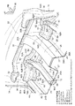
図2、図3に示されるように、車両の車体前部上側には、車体前後方向に沿って延在して車体骨格部材を構成する矩形閉断面形状のフロントサイドメンバ12が左右一対で配設されている。なお、各フロントサイドメンバ12の前端部には、車幅方向に延在する矩形閉断面形状のフロントバンパリインフォースメント(図示省略)が架設されている。
As shown in FIGS. 2 and 3, a pair of left and right
各フロントサイドメンバ12の後部には、車体後方下側へ向けて傾斜するとともに、下側へ凸となる断面ハット型形状に形成されたキック部14が一体に連設されている。各キック部14は、エンジンコンパートメントルーム18と車室20とを区画するダッシュパネル22の裏面(前面)と車体フロアを構成するフロアパネル24の裏面(下面)とに跨って、左右のフランジ部14Aが接合(溶接)されることで、閉断面構造を構成するようになっている。
A
なお、ダッシュパネル22とフロアパネル24との連設位置は、図3に示される位置に限定されるものではない。例えば、その連設位置は、後述するダッシュロアクロスメンバ50の前側であってもよいし、後側であってもよい。つまり、後述するダッシュロアクロスメンバ50は、ダッシュパネル22とフロアパネル24とに跨って接合されていてもよいし、ダッシュパネル22のみ又はフロアパネル24のみに接合されていてもよい。
In addition, the connection position of the
また、図2、図3に示されるように、フロントサイドメンバ12の上壁13における後端部は、上方へ向かって折り曲げ成形されたフランジ部13Aとされている、そして、そのフランジ部13Aが、ダッシュパネル22の裏面(前面)にスポット溶接によって接合されている。
2 and 3, the rear end portion of the
また、各キック部14の後部には、車体後方側へ延在するとともに、下側へ凸となる断面ハット型形状に形成されたアンダーリインフォースメント16が一体に連設されている。各アンダーリインフォースメント16は、ダッシュパネル22から車体後方側へ向けて一体的に連続するフロアパネル24の裏面(下面)に、左右のフランジ部16Aが接合(溶接)されることで、閉断面構造を構成するようになっている。
In addition, an under-
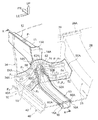
また、図1、図2に示されるように、車両の車幅方向中央下部には、車体前後方向に延在して車体骨格部材を構成するフロアトンネル部26が配設されている。フロアトンネル部26は、上側へ凸となる断面ハット型形状に形成されており、左右のフランジ部26Aには、フロアパネル24の車幅方向内側端部における裏面(下面)が接合(溶接)されるようになっている。
As shown in FIGS. 1 and 2, a
なお、フロアパネル24の車幅方向内側端部は、上方へ向かって折り曲げ成形されたフランジ部24Aとされており、各フランジ部24Aが、フロアトンネル部26の左右の側壁27にそれぞれ接合(溶接)されている。また、フロアトンネル部26の前端部は、ダッシュパネル22の表面(後面)における車幅方向中央下部に一体的に接合されている。
In addition, the vehicle width direction inner side edge part of the
更に、フロアトンネル部26の上部には、例えば図示しないシフトレバーの挿通孔等が形成された断面略逆「U」字形状のパネル部材28が設けられている。このパネル部材28の前端部28Aは、ダッシュアッパークロスメンバ30に例えばボルト・ナット(図示省略)によって接合されている。
Furthermore, a
図1〜図3に示されるように、ダッシュアッパークロスメンバ30は、車幅方向略全体に亘って延在されるとともに、後側へ凸となる断面ハット型形状に形成されており、その上フランジ部30A及び下フランジ部30Bが、それぞれダッシュパネル22の表面(後面)における上部に接合(溶接)されることで、閉断面構造を構成するようになっている。
As shown in FIGS. 1 to 3, the dash
なお、図3に示されるように、ダッシュアッパークロスメンバ30の下フランジ部30Bの一部は、ダッシュパネル22を挟んで各フロントサイドメンバ12の上壁13におけるフランジ部13Aと対向配置されている。これにより、フロントサイドメンバ12に入力された衝突荷重がダッシュアッパークロスメンバ30にも伝達される構成になっている。
As shown in FIG. 3, a part of the
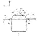
また、図1、図2、図6に示されるように、ダッシュパネル22の左右両辺縁部は、車幅方向外側で車体上下方向に延在された左右のフロントピラー34のインナパネル36に接合されている。そして、ダッシュアッパークロスメンバ30の車幅方向両端部32は、ダッシュパネル22の左右両辺縁部及び左右のフロントピラー34のインナパネル36にボルト・ナット(図示省略)によって接合されている。
As shown in FIGS. 1, 2, and 6, the left and right edges of the
各フロントピラー34は、内側へ凸となる断面ハット型形状に形成されたインナパネル36の前後のフランジ部36A(図6参照)と、外側へ凸となる断面ハット型形状に形成されたアウタパネル38の前後のフランジ部38A(図6参照)と、が互いに接合(溶接)されることで、閉断面構造に構成されている。
Each
また、図1、図2、図6、図7に示されるように、車両の車幅方向外側下部には、車体前後方向に延在して車体骨格部材を構成するロッカ40が配設されている。ロッカ40は、内側へ凸となる断面ハット型形状のインナパネル42と、外側へ凸となる断面ハット型形状のアウタパネル44と、インナパネル42とアウタパネル44との間に設けられる略平板状のロッカリインフォースメント46と、を有している。
In addition, as shown in FIGS. 1, 2, 6, and 7, a
そして、インナパネル42の上フランジ部42A及び下フランジ部42Bと、アウタパネル44の上フランジ部44A及び下フランジ部44Bとが、それぞれフランジ部36Aと一体化されたロッカリインフォースメント46の内側面及び外側面に接合(溶接)されることで、閉断面構造のロッカ40が構成されるようになっている。
Then, the
なお、図1に示されるように、フロアパネル24の車幅方向外側端部は、上方へ向かって折り曲げ成形されたフランジ部24Bとされており、各フランジ部24Bが、ロッカ40のインナパネル42にそれぞれ接合(溶接)されている。つまり、ロッカ40は、フロアパネル24の車幅方向外側で車体前後方向に延在されている。
As shown in FIG. 1, the outer end of the
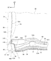
図1〜図3に示されるように、ダッシュパネル22及びフロアパネル24を挟んで、キック部14とは表裏反対側のダッシュパネル22の表面(後面)及びフロアパネル24の表面(上面)には(ダッシュパネル22の下側で、かつフロアパネル24の前側には)、車幅方向に延在するダッシュロアクロスメンバ50が左右一対で配設されている。
As shown in FIGS. 1 to 3, the surface (rear surface) of the
車体下部構造10を構成するダッシュロアクロスメンバ50は、フロアトンネル部26とロッカ40とを車幅方向で連結するようになっており、ダッシュロアクロスメンバ50の車幅方向内側端部は、上方へ向かって折り曲げ成形されたフランジ部50Aとされている。そして、各フランジ部50Aが、それぞれフロアパネル24のフランジ部24Aとフロアトンネル部26の側壁27とに跨って(又は側壁27のみに)、スポット溶接によって接合されている。
The dash
図5に示されるように、ダッシュロアクロスメンバ50は、フロアパネル24の表面(上面)側で車幅方向に延在するとともに、上側へ凸となる断面ハット型形状の第1クロスメンバ52と、ダッシュパネル22の表面(後面)側(第1クロスメンバ52の車体前方側)で車幅方向に延在するとともに、上側へ凸となる断面ハット型形状の第2クロスメンバ54と、を有している。
As shown in FIG. 5, the dash
そして、ダッシュロアクロスメンバ50は、第1クロスメンバ52の車幅方向略中央部(平面視で左右のフランジ部14Aの間)と、第2クロスメンバ54の車幅方向略中央部(平面視で左右のフランジ部14Aの間)と、を車体前後方向で一体に連結する(車体前後方向に延在する)とともに、上側へ凸となる断面ハット型形状の連結部材56を有している。
The dash
更に、ダッシュロアクロスメンバ50は、第1クロスメンバ52の前側のフランジ部と、第2クロスメンバ54の後側のフランジ部と、連結部材56の左右両側のフランジ部と、が互いに一体に連設されることで、第1クロスメンバ52と第2クロスメンバ54と連結部材56とが一体化されるようになっている。
Further, the dash
なお、ダッシュロアクロスメンバ50は、第1クロスメンバ52の前側のフランジ部と、第2クロスメンバ54の後側のフランジ部と、連結部材56の左右両側のフランジ部と、が互いに一体に連設されない(平面視で「エ」字状に形成された)構成とされていてもよい。
In the dash
但し、上記各フランジ部が互いに一体に連設されて(以下、その一体に連設された部位を「連設部58」という)、第1クロスメンバ52と第2クロスメンバ54と連結部材56とが一体化されていると、それらの強度(剛性)が向上されるとともに、ダッシュロアクロスメンバ50において、部品点数の削減が図れる。
However, the flange portions are integrally connected to each other (hereinafter, the integrally connected portions are referred to as “
また、図3に示されるように、第1クロスメンバ52の後側のフランジ部52Aが、フロアパネル24の表面(上面)にスポット溶接によって接合され、第2クロスメンバ54の前側のフランジ部54Aが、ダッシュパネル22の表面(後面)にスポット溶接によって接合されている。
Further, as shown in FIG. 3, the
これにより、ダッシュロアクロスメンバ50(第1クロスメンバ52、第2クロスメンバ54、連結部材56)が、ダッシュパネル22及びフロアパネル24とで、閉断面構造を構成するようになっており、その閉断面構造が容易に構成されるようになっている。つまり、ダッシュロアクロスメンバ50の車体への組付性が向上されるようになっている。
As a result, the dash lower cross member 50 (the
なお、上記したように、ダッシュパネル22とフロアパネル24との連設位置の設定により、ダッシュロアクロスメンバ50は、ダッシュパネル22のみとで閉断面構造を構成するようになっていてもよいし、フロアパネル24のみとで閉断面構造を構成するようになっていてもよい。
As described above, the dash
また、第1クロスメンバ52のフランジ部52A及び第2クロスメンバ54のフランジ部54Aは、フロアパネル24を挟んでキック部14のフランジ部14Aともスポット溶接されている。そして、連結部材56の左右両側(第1クロスメンバ52と第2クロスメンバ54との間)における連設部58も、フロアパネル24を挟んでキック部14のフランジ部14Aとスポット溶接されている(図2参照)。
The
換言すれば、左右のスポット溶接部の間に連結部材56が設けられるようになっており、平面視及び背面視で、連結部材56がキック部14(フロントサイドメンバ12)と重なる位置に配置されている。つまり、連結部材56は、キック部14(フロントサイドメンバ12)の上方側で、かつキック部14(フロントサイドメンバ12)の延在方向に沿って配置されている。
In other words, the connecting
また、第2クロスメンバ54の前側のフランジ部54Aは、図3に示される側断面視でフロントサイドメンバ12よりも下側に配置されているが、フロントサイドメンバ12に入力された衝突荷重の伝達効率を向上させるために、フロントサイドメンバ12の上壁13に近接する高さ位置まで延設されていてもよい。
Further, the
また、図1、図2、図6、図7に示されるように、ダッシュロアクロスメンバ50の車幅方向外側端部は、上方又は後方へ向かって折り曲げ成形されたフランジ部50Bとされている。そして、各フランジ部50Bが、ロッカ40の前端部40Aとフロントピラー34の下端部(下側)34Aとに跨って、スポット溶接によって接合(結合)されている。
As shown in FIGS. 1, 2, 6, and 7, the outer end in the vehicle width direction of the dash
詳細に説明すると、第1クロスメンバ52(後側のフランジ部52Aを含む)及び連設部58の車幅方向外側端部に形成されたフランジ部50Bの一部が、ロッカ40の前端部40Aにおけるインナパネル42(及びフロアパネル24のフランジ部24B)にスポット溶接によって接合されている(図7参照)。
More specifically, a part of the first cross member 52 (including the
そして、第2クロスメンバ54(前側のフランジ部54Aを含む)の車幅方向外側端部に形成されたフランジ部50Bの一部が、ロッカ40の前端部40Aにおけるインナパネル42及びフロントピラー34の下端部34Aにおけるインナパネル36にスポット溶接によって接合されている(図6、図7参照)。
A part of the
このように、閉断面構造を構成する第1クロスメンバ52及び第2クロスメンバ54の車幅方向外側端部が、ロッカ40の前端部40A及びフロントピラー34の下端部34Aに接合されているので、ロッカ40の前端部40A及びフロントピラー34の下端部34Aの強度が、ダッシュロアクロスメンバ50によって補強される。
Thus, the vehicle width direction outer side end portions of the
したがって、例えば微小ラップ衝突やオフセット衝突によって前輪(図示省略)が後退し、ロッカ40の前端部40Aやフロントピラー34の下端部34Aに衝突したときには、その衝突荷重を第1クロスメンバ52や第2クロスメンバ54を介してフロアトンネル部26へ伝達することができる。
Therefore, for example, when the front wheel (not shown) moves backward due to a minute lap collision or offset collision and collides with the
また、図1〜図4に示されるように、フロアパネル24を挟んで、キック部14及びアンダーリインフォースメント16とは反対側のフロアパネル24の表面(上面)には、車体前後方向に延在するとともに、上側へ凸となる断面ハット型形状のアッパーリインフォースメント60が配設されている。
As shown in FIGS. 1 to 4, on the surface (upper surface) of the
フロアリインフォースメントとしてのアッパーリインフォースメント60は、左右のフランジ部60Aが、それぞれフロアパネル24の表面(上面)にスポット溶接によって接合されることで、閉断面構造を構成するようになっている。そして、アッパーリインフォースメント60の前端部62は、ダッシュロアクロスメンバ50にスポット溶接によって接合されることで、閉断面構造を構成するようになっている。
The
詳細に説明すると、アッパーリインフォースメント60の前端部62は、平面視略「T」字形状に形成されており、その車幅方向に延在する先端部62Aが、第2クロスメンバ54の上壁にスポット溶接によって接合されている。そして、その先端部62Aの後方側に形成された幅狭部62Bの下方側から左右に張り出す張出部62Cが、連結部材56の上壁にスポット溶接によって接合されている。
More specifically, the
これにより、アッパーリインフォースメント60の前端部62が、連結部材56全体を上方から覆う構成になっており、連結部材56が、アッパーリインフォースメント60の一部を構成するようになっている。なお、図2〜図4において、ダッシュロアクロスメンバ50及びアッパーリインフォースメント60のスポット溶接部を「×」で示すが、スポット溶接部は、図示の位置に限定されるものではない。
Accordingly, the
以上のような構成の車体下部構造10において、次にその作用について説明する。
Next, the operation of the vehicle body
車両がオフセット衝突又はフルラップ衝突した場合には、図2に示されるように、フロントサイドメンバ12に衝突荷重F1が入力される。フロントサイドメンバ12に入力された衝突荷重F1は、キック部14を介してアンダーリインフォースメント16へ伝達されるとともに、ダッシュロアクロスメンバ50へも伝達される。これにより、キック部14及びアンダーリインフォースメント16の荷重分担が軽減される。
When the vehicle has an offset collision or a full lap collision, a collision load F1 is input to the
ダッシュロアクロスメンバ50に伝達(入力)された衝突荷重F1は、第2クロスメンバ54によってフロントピラー34及びフロアトンネル部26へ伝達されるとともに、連結部材56によって第1クロスメンバ52へ伝達され、その第1クロスメンバ52からロッカ40及びフロアトンネル部26へ伝達される。
The collision load F1 transmitted (input) to the dash
そして更に、ダッシュロアクロスメンバ50に伝達(入力)された衝突荷重F1は、連結部材56からアッパーリインフォースメント60へ伝達される。このように、ダッシュロアクロスメンバ50に伝達(入力)された衝突荷重F1は、フロアトンネル部26、フロントピラー34、ロッカ40、アッパーリインフォースメント60へ効率よく分散される。
Further, the collision load F1 transmitted (input) to the dash
また、アッパーリインフォースメント60の前端部62は、上方から連結部材56を覆うようにダッシュロアクロスメンバ50に接合されている。したがって、キック部14の車体後方側への移動(後退)により、ダッシュパネル22(及びフロアパネル24)を介してダッシュロアクロスメンバ50に加えられる(キック部14の下端部を支点とした)車体上方側への曲げモーメントをアッパーリインフォースメント60によって抑えることができ、その曲げモーメントを低減させることができる。
Further, the
つまり、このアッパーリインフォースメント60により、オフセット衝突時やフルラップ衝突時におけるキック部14の曲げ耐力(断面耐力)を向上させることができる。よって、キック部14の下端部を支点としたフロントサイドメンバ12の車体上方側への折れ曲がり(起き上がり)変形を抑制又は防止することができ、フロントサイドメンバ12及びキック部14が後退することによる車室20の変形を抑制又は防止することができる。
That is, the
また、車両が微小ラップ衝突又はオフセット衝突した場合には、前輪(図示省略)が車体後方側へ移動(後退)してロッカ40の前端部40A及びフロントピラー34の下端部34Aに衝突する。つまり、図2に示されるように、ロッカ40の前端部40A及びフロントピラー34の下端部34Aに衝突荷重F2が入力される。
Further, when the vehicle has a minute lap collision or an offset collision, the front wheel (not shown) moves (retracts) to the rear side of the vehicle body and collides with the
フロントピラー34の下端部34Aに入力された衝突荷重F2の一部は、フロントピラー34へ伝達されるとともに、ダッシュロアクロスメンバ50の第2クロスメンバ54によってフロアトンネル部26へ伝達される。なお、その衝突荷重F2の一部は、第2クロスメンバ54から連結部材56を介して第1クロスメンバ52へも伝達され、第1クロスメンバ52によってフロアトンネル部26へ伝達される。
A part of the collision load F <b> 2 input to the
一方、ロッカ40の前端部40Aに入力された衝突荷重F2の一部は、ロッカ40へ伝達されるとともに、ダッシュロアクロスメンバ50の第1クロスメンバ52によってフロアトンネル部26へ伝達される。なお、その衝突荷重F2の一部は、第1クロスメンバ52から連結部材56を介して第2クロスメンバ54へも伝達され、第2クロスメンバ54によってフロアトンネル部26へ伝達される。
On the other hand, a part of the collision load F <b> 2 input to the
そして更に、ロッカ40の前端部40Aに入力された衝突荷重F2の一部は、連結部材56を介してアッパーリインフォースメント60へも伝達される。このように、フロントピラー34の下端部34A及びロッカ40の前端部40Aからダッシュロアクロスメンバ50に伝達(入力)された衝突荷重F2は、フロアトンネル部26やアッパーリインフォースメント60へ効率よく分散される。
Further, a part of the collision load F <b> 2 input to the
よって、微小ラップ衝突時やオフセット衝突時において、フロントピラー34及びロッカ40の荷重分担を軽減させることができ、ロッカ40の車幅方向内側への折れ曲がり変形(内折れ)を抑制する(曲げモーメントを低減させる)ことができる。つまり、ロッカ40が車幅方向内側へ進入することによる車室20の変形を抑制又は防止することができる。
Therefore, the load sharing of the
また、ダッシュロアクロスメンバ50により、フロントピラー34の下端部34Aやロッカ40の前端部40Aに入力された衝突荷重の一部をフロアトンネル部26に分担させることができるため、フロントピラー34やロッカ40の局所的な変形を抑制することができる。したがって、フロントピラー34やロッカ40等の車体骨格部材の耐力を下げる(例えば板厚を減らす)ことができ、車両の軽量化及び低コスト化を図ることができる。
Further, since the dash
以上、本実施形態に係る車体下部構造10について、図面を基に説明したが、本実施形態に係る車体下部構造10は、図示のものに限定されるものではなく、本発明の要旨を逸脱しない範囲内において、適宜設計変更可能なものである。例えば、連結部材56は、車体前後方向に延在される構成に限定されるものではなく、平面視で車体前後方向及び車幅方向に対して斜めに延在される構成とされていてもよい。
The vehicle body
したがって、連結部材56を設ける位置も、第1クロスメンバ52や第2クロスメンバ54の車幅方向略中央部(平面視で左右のフランジ部14Aの間)に限定されるものではない。また、ダッシュパネル22とフロアパネル24とは、図3に示されるように、別体とされて一体的に連設されているが、これに限定されるものではなく、両者が一体化された構成とされていてもよい。
Therefore, the position where the connecting
また、本実施形態に係る車体下部構造10では、ダッシュパネル22やフロアパネル24等に、ダッシュロアクロスメンバ50やアッパーリインフォースメント60等をスポット溶接によって接合する構成としたが、接合手段は、これに限定されるものではない。例えばレーザーによる溶接半径を徐々に小さくしていくことでスポット状に接合するレーザー溶接(特開2012−115876号公報参照)によって接合する構成にしてもよい。
In the vehicle body
10 車体下部構造
22 ダッシュパネル
24 フロアパネル
34 フロントピラー
40 ロッカ
52 第1クロスメンバ
54 第2クロスメンバ
56 連結部材
60 アッパーリインフォースメント(フロアリインフォースメント)
DESCRIPTION OF
Claims (7)
ダッシュパネルの下側で車幅方向に延在されるとともに車体上方側へ凸となる断面ハット型形状に形成され、車幅方向外側端部が前記ロッカに結合された第1クロスメンバと、
前記第1クロスメンバの車体前方側で車幅方向に延在されるとともに車体上方側へ凸となる断面ハット型形状に形成された第2クロスメンバと、
車体上方側へ凸となる断面ハット型形状に形成されて前記第1クロスメンバと前記第2クロスメンバとを連結するとともに、前記ダッシュパネル又は前記フロアパネルとで閉断面構造を構成する連結部材と、
を備えた車体下部構造。 A rocker extending in the vehicle longitudinal direction outside the floor panel in the vehicle width direction;
Is formed in the cross-sectional hat shape that is convex to the extended Rutotomoni vehicle upper side in the vehicle width direction below the dash panel, a first cross member in the vehicle width direction outside end portion is coupled to the rocker,
A second cross member formed on the cross-sectional hat shape that is convex to the extended Rutotomoni vehicle upper side in the vehicle width direction in the vehicle body front side of the first cross member,
A connecting member that is formed in a hat-shaped cross section that protrudes upward from the vehicle body , connects the first cross member and the second cross member, and forms a closed cross-sectional structure with the dash panel or the floor panel; ,
Body lower structure with
前記連結部材は、前記フロアリインフォースメントの一部を構成することを特徴とする請求項1又は請求項2に記載の車体下部構造。 A floor reinforcement that extends in the longitudinal direction of the vehicle body and forms a closed section structure with the floor panel,
The vehicle body lower part structure according to claim 1, wherein the connecting member constitutes a part of the floor reinforcement.
平面視で前記連結部材が前記サイドメンバと重なる位置に配置されていることを特徴とする請求項1〜請求項6の何れか1項に記載の車体下部構造。 It has side members that extend in the longitudinal direction of the car body,
The vehicle body lower structure according to any one of claims 1 to 6, wherein the connecting member is disposed at a position overlapping the side member in a plan view.
Priority Applications (2)
| Application Number | Priority Date | Filing Date | Title |
|---|---|---|---|
| JP2013243338A JP5924331B2 (en) | 2013-11-25 | 2013-11-25 | Lower body structure |
| US14/547,790 US9180916B2 (en) | 2013-11-25 | 2014-11-19 | Vehicle body lower section structure |
Applications Claiming Priority (1)
| Application Number | Priority Date | Filing Date | Title |
|---|---|---|---|
| JP2013243338A JP5924331B2 (en) | 2013-11-25 | 2013-11-25 | Lower body structure |
Publications (2)
| Publication Number | Publication Date |
|---|---|
| JP2015101217A JP2015101217A (en) | 2015-06-04 |
| JP5924331B2 true JP5924331B2 (en) | 2016-05-25 |
Family
ID=53182031
Family Applications (1)
| Application Number | Title | Priority Date | Filing Date |
|---|---|---|---|
| JP2013243338A Expired - Fee Related JP5924331B2 (en) | 2013-11-25 | 2013-11-25 | Lower body structure |
Country Status (2)
| Country | Link |
|---|---|
| US (1) | US9180916B2 (en) |
| JP (1) | JP5924331B2 (en) |
Cited By (1)
| Publication number | Priority date | Publication date | Assignee | Title |
|---|---|---|---|---|
| US11572104B2 (en) * | 2020-09-04 | 2023-02-07 | Toyota Jidosha Kabushiki Kaisha | Vehicle body |
Families Citing this family (33)
| Publication number | Priority date | Publication date | Assignee | Title |
|---|---|---|---|---|
| FR2989053B1 (en) * | 2012-04-05 | 2014-03-21 | Renault Sa | CHASSIS OF A MOTOR VEHICLE COMPRISING MEANS FOR ABSORPTION OF A FRONTAL SHOCK |
| DE102013012478A1 (en) * | 2013-07-26 | 2015-01-29 | GM Global Technology Operations LLC (n. d. Gesetzen des Staates Delaware) | Body component and method for producing a body component |
| FR3020793B1 (en) * | 2014-05-07 | 2016-10-21 | Renault Sa | FRONT APRON FOR MOTOR VEHICLE. |
| JP6011583B2 (en) * | 2014-07-04 | 2016-10-19 | トヨタ自動車株式会社 | Vehicle lower structure |
| JP6112083B2 (en) * | 2014-08-21 | 2017-04-12 | トヨタ自動車株式会社 | Body front structure |
| JP6522982B2 (en) * | 2015-02-18 | 2019-05-29 | 本田技研工業株式会社 | Body structure |
| KR101664065B1 (en) * | 2015-03-17 | 2016-10-10 | 현대자동차 주식회사 | Front vehicle body reinforcing structure and assembling method thereof |
| WO2016148057A1 (en) * | 2015-03-17 | 2016-09-22 | 本田技研工業株式会社 | Vehicle body structure |
| EP3100935B1 (en) * | 2015-06-04 | 2019-05-01 | FCA Italy S.p.A. | Motor-vehicle floor panel structure |
| JP6337860B2 (en) * | 2015-09-15 | 2018-06-06 | トヨタ自動車株式会社 | Vehicle skeleton structure |
| JP6332245B2 (en) * | 2015-11-25 | 2018-05-30 | トヨタ自動車株式会社 | Vehicle lower structure |
| WO2017135163A1 (en) * | 2016-02-05 | 2017-08-10 | 新日鐵住金株式会社 | Vehicle front-end structure |
| JP6235637B2 (en) * | 2016-02-29 | 2017-11-22 | 本田技研工業株式会社 | Auto body structure |
| JP6547772B2 (en) * | 2017-01-24 | 2019-07-24 | トヨタ自動車株式会社 | Vehicle floor structure |
| KR102354133B1 (en) * | 2017-07-12 | 2022-01-24 | 현대자동차주식회사 | Support structure of dash panel for vehicle |
| JP6532513B2 (en) * | 2017-09-15 | 2019-06-19 | 本田技研工業株式会社 | Body structure |
| CN107963130B (en) * | 2017-11-22 | 2019-08-13 | 威马智慧出行科技(上海)有限公司 | Front wall assembly and automobile including it |
| JP6881325B2 (en) * | 2018-01-16 | 2021-06-02 | マツダ株式会社 | Lower body structure |
| CN111867747B (en) * | 2018-02-28 | 2022-05-13 | 杰富意钢铁株式会社 | Metal plate for press molding, press molding device, and method for manufacturing press member |
| JP7035848B2 (en) * | 2018-06-27 | 2022-03-15 | トヨタ自動車株式会社 | Vehicle lower body structure |
| JP7052628B2 (en) * | 2018-08-07 | 2022-04-12 | トヨタ自動車株式会社 | Vehicle front structure |
| JP7095476B2 (en) * | 2018-08-07 | 2022-07-05 | トヨタ自動車株式会社 | Vehicle front structure |
| JP7044009B2 (en) | 2018-08-10 | 2022-03-30 | トヨタ自動車株式会社 | Body structure |
| CN109484262B (en) * | 2018-12-17 | 2020-07-28 | 安徽江淮汽车集团股份有限公司 | Vehicle passenger compartment |
| JP7188328B2 (en) * | 2019-09-06 | 2022-12-13 | トヨタ自動車株式会社 | Vehicle bottom structure and method for manufacturing vehicle bottom structure |
| JP7264846B2 (en) * | 2020-03-16 | 2023-04-25 | トヨタ自動車株式会社 | car body |
| DE102020121094B3 (en) * | 2020-08-11 | 2021-10-07 | Bayerische Motoren Werke Aktiengesellschaft | Body structure for a motor vehicle |
| JP7284131B2 (en) * | 2020-09-03 | 2023-05-30 | トヨタ自動車株式会社 | vehicle |
| JP7372272B2 (en) * | 2021-01-26 | 2023-10-31 | トヨタ自動車株式会社 | vehicle |
| JP7487705B2 (en) * | 2021-04-30 | 2024-05-21 | トヨタ自動車株式会社 | Floor Structure |
| JP7553414B2 (en) | 2021-09-09 | 2024-09-18 | トヨタ自動車株式会社 | vehicle |
| JP7485708B2 (en) * | 2022-03-10 | 2024-05-16 | 本田技研工業株式会社 | Vehicle underbody structure |
| FR3133362A1 (en) * | 2022-03-11 | 2023-09-15 | Psa Automobiles Sa | Reinforcement plate for a front structure apron. |
Family Cites Families (10)
| Publication number | Priority date | Publication date | Assignee | Title |
|---|---|---|---|---|
| JP3275890B2 (en) * | 1999-09-08 | 2002-04-22 | 日産自動車株式会社 | Car body structure |
| JP4346313B2 (en) * | 2003-01-08 | 2009-10-21 | 富士重工業株式会社 | Auto body front structure |
| JP2005153801A (en) * | 2003-11-27 | 2005-06-16 | Fuji Heavy Ind Ltd | Toe board for vehicle |
| JP4725249B2 (en) * | 2005-08-26 | 2011-07-13 | マツダ株式会社 | Auto body structure |
| JP4546992B2 (en) * | 2007-09-18 | 2010-09-22 | 富士重工業株式会社 | Front body structure of automobile |
| JP2009248593A (en) | 2008-04-01 | 2009-10-29 | Toyota Motor Corp | Vehicle body framework structure |
| CN102171092B (en) | 2008-12-22 | 2014-03-19 | 丰田自动车株式会社 | Structure for front portion of vehicle body |
| JP5609595B2 (en) | 2010-12-01 | 2014-10-22 | トヨタ自動車株式会社 | Laser welding method |
| JP5957721B2 (en) * | 2012-02-13 | 2016-07-27 | 本田技研工業株式会社 | Vehicle structure |
| WO2014162493A1 (en) | 2013-04-01 | 2014-10-09 | トヨタ自動車株式会社 | Vehicle body structure |
-
2013
- 2013-11-25 JP JP2013243338A patent/JP5924331B2/en not_active Expired - Fee Related
-
2014
- 2014-11-19 US US14/547,790 patent/US9180916B2/en not_active Expired - Fee Related
Cited By (1)
| Publication number | Priority date | Publication date | Assignee | Title |
|---|---|---|---|---|
| US11572104B2 (en) * | 2020-09-04 | 2023-02-07 | Toyota Jidosha Kabushiki Kaisha | Vehicle body |
Also Published As
| Publication number | Publication date |
|---|---|
| US20150145284A1 (en) | 2015-05-28 |
| US9180916B2 (en) | 2015-11-10 |
| JP2015101217A (en) | 2015-06-04 |
Similar Documents
| Publication | Publication Date | Title |
|---|---|---|
| JP5924331B2 (en) | Lower body structure | |
| JP5907147B2 (en) | Lower body structure | |
| JP6079662B2 (en) | Lower body structure | |
| US9873457B2 (en) | Vehicle skeleton structure | |
| KR101763793B1 (en) | Vehicle body front portion structure | |
| JP6288069B2 (en) | Car body rear structure | |
| JP5963060B2 (en) | Floor structure at the rear of the car body | |
| JP6610576B2 (en) | Vehicle skeleton structure | |
| JP6495401B2 (en) | Body structure | |
| JP6137105B2 (en) | Battery drive battery mounting structure | |
| JP2017144955A (en) | Vehicle body structure | |
| JP7264846B2 (en) | car body | |
| JP6546809B2 (en) | Body structure of car | |
| JP2016196207A (en) | Rear vehicle body structure of vehicle | |
| JP6176086B2 (en) | Lower body structure | |
| JP2015116979A (en) | Vehicle body lower part structure | |
| JP6090181B2 (en) | Lower body structure | |
| JP2008195252A (en) | Bottom structure of vehicle body of vehicle with frame | |
| JP6213171B2 (en) | Vehicle floor structure | |
| JP6603578B2 (en) | Suspension member reinforcement structure | |
| JP5846095B2 (en) | Cowl structure | |
| JP6136698B2 (en) | Body front structure | |
| WO2015076023A1 (en) | Vehicle-chassis-rear-section structure | |
| JP5084855B2 (en) | Body floor structure | |
| WO2017217117A1 (en) | Vehicle frame structure |
Legal Events
| Date | Code | Title | Description |
|---|---|---|---|
| A621 | Written request for application examination |
Free format text: JAPANESE INTERMEDIATE CODE: A621 Effective date: 20150513 |
|
| A131 | Notification of reasons for refusal |
Free format text: JAPANESE INTERMEDIATE CODE: A131 Effective date: 20150825 |
|
| A521 | Request for written amendment filed |
Free format text: JAPANESE INTERMEDIATE CODE: A523 Effective date: 20151021 |
|
| TRDD | Decision of grant or rejection written | ||
| A01 | Written decision to grant a patent or to grant a registration (utility model) |
Free format text: JAPANESE INTERMEDIATE CODE: A01 Effective date: 20160322 |
|
| A61 | First payment of annual fees (during grant procedure) |
Free format text: JAPANESE INTERMEDIATE CODE: A61 Effective date: 20160404 |
|
| R151 | Written notification of patent or utility model registration |
Ref document number: 5924331 Country of ref document: JP Free format text: JAPANESE INTERMEDIATE CODE: R151 |
|
| LAPS | Cancellation because of no payment of annual fees |