EP3758580B1 - Erhalt von bildern zur verwendung bei der bestimmung einer oder mehrerer eigenschaften der haut einer person - Google Patents
Erhalt von bildern zur verwendung bei der bestimmung einer oder mehrerer eigenschaften der haut einer person Download PDFInfo
- Publication number
- EP3758580B1 EP3758580B1 EP19706671.5A EP19706671A EP3758580B1 EP 3758580 B1 EP3758580 B1 EP 3758580B1 EP 19706671 A EP19706671 A EP 19706671A EP 3758580 B1 EP3758580 B1 EP 3758580B1
- Authority
- EP
- European Patent Office
- Prior art keywords
- light
- skin
- image sensor
- sensor unit
- arrangement
- Prior art date
- Legal status (The legal status is an assumption and is not a legal conclusion. Google has not performed a legal analysis and makes no representation as to the accuracy of the status listed.)
- Active
Links
- 238000000034 method Methods 0.000 claims description 48
- 230000003287 optical effect Effects 0.000 claims description 34
- 230000008569 process Effects 0.000 claims description 21
- 238000012545 processing Methods 0.000 claims description 9
- 238000009826 distribution Methods 0.000 claims description 5
- 238000002847 impedance measurement Methods 0.000 claims description 5
- 230000036571 hydration Effects 0.000 claims description 4
- 238000006703 hydration reaction Methods 0.000 claims description 4
- 238000012935 Averaging Methods 0.000 claims description 3
- 238000000513 principal component analysis Methods 0.000 claims description 3
- 238000005286 illumination Methods 0.000 description 15
- 206010000496 acne Diseases 0.000 description 14
- 239000011148 porous material Substances 0.000 description 14
- 208000012641 Pigmentation disease Diseases 0.000 description 12
- 230000036548 skin texture Effects 0.000 description 12
- 210000004209 hair Anatomy 0.000 description 9
- 230000019612 pigmentation Effects 0.000 description 9
- 230000006870 function Effects 0.000 description 7
- 238000005259 measurement Methods 0.000 description 5
- 241001635598 Enicostema Species 0.000 description 4
- 206010027626 Milia Diseases 0.000 description 4
- 239000007787 solid Substances 0.000 description 4
- 229920001621 AMOLED Polymers 0.000 description 3
- 238000004458 analytical method Methods 0.000 description 3
- 230000000694 effects Effects 0.000 description 3
- 239000004065 semiconductor Substances 0.000 description 3
- 238000004590 computer program Methods 0.000 description 2
- 238000010586 diagram Methods 0.000 description 2
- 238000010191 image analysis Methods 0.000 description 2
- 239000011368 organic material Substances 0.000 description 2
- 230000036555 skin type Effects 0.000 description 2
- 125000006850 spacer group Chemical group 0.000 description 2
- 241001465754 Metazoa Species 0.000 description 1
- 230000004913 activation Effects 0.000 description 1
- 238000003491 array Methods 0.000 description 1
- 230000008901 benefit Effects 0.000 description 1
- 230000010267 cellular communication Effects 0.000 description 1
- 238000004891 communication Methods 0.000 description 1
- 230000000295 complement effect Effects 0.000 description 1
- 238000013500 data storage Methods 0.000 description 1
- 230000009849 deactivation Effects 0.000 description 1
- 230000001419 dependent effect Effects 0.000 description 1
- 230000007774 longterm Effects 0.000 description 1
- 238000010801 machine learning Methods 0.000 description 1
- 239000011159 matrix material Substances 0.000 description 1
- 229910044991 metal oxide Inorganic materials 0.000 description 1
- 150000004706 metal oxides Chemical class 0.000 description 1
- 238000010295 mobile communication Methods 0.000 description 1
- 210000002374 sebum Anatomy 0.000 description 1
- 230000035945 sensitivity Effects 0.000 description 1
- 230000003068 static effect Effects 0.000 description 1
Images


Classifications
-
- G—PHYSICS
- G06—COMPUTING; CALCULATING OR COUNTING
- G06T—IMAGE DATA PROCESSING OR GENERATION, IN GENERAL
- G06T7/00—Image analysis
- G06T7/0002—Inspection of images, e.g. flaw detection
- G06T7/0012—Biomedical image inspection
-
- A—HUMAN NECESSITIES
- A61—MEDICAL OR VETERINARY SCIENCE; HYGIENE
- A61B—DIAGNOSIS; SURGERY; IDENTIFICATION
- A61B5/00—Measuring for diagnostic purposes; Identification of persons
-
- A—HUMAN NECESSITIES
- A61—MEDICAL OR VETERINARY SCIENCE; HYGIENE
- A61B—DIAGNOSIS; SURGERY; IDENTIFICATION
- A61B5/00—Measuring for diagnostic purposes; Identification of persons
- A61B5/0059—Measuring for diagnostic purposes; Identification of persons using light, e.g. diagnosis by transillumination, diascopy, fluorescence
- A61B5/0062—Arrangements for scanning
- A61B5/0064—Body surface scanning
-
- A—HUMAN NECESSITIES
- A61—MEDICAL OR VETERINARY SCIENCE; HYGIENE
- A61B—DIAGNOSIS; SURGERY; IDENTIFICATION
- A61B5/00—Measuring for diagnostic purposes; Identification of persons
- A61B5/0059—Measuring for diagnostic purposes; Identification of persons using light, e.g. diagnosis by transillumination, diascopy, fluorescence
- A61B5/0077—Devices for viewing the surface of the body, e.g. camera, magnifying lens
-
- A—HUMAN NECESSITIES
- A61—MEDICAL OR VETERINARY SCIENCE; HYGIENE
- A61B—DIAGNOSIS; SURGERY; IDENTIFICATION
- A61B5/00—Measuring for diagnostic purposes; Identification of persons
- A61B5/05—Detecting, measuring or recording for diagnosis by means of electric currents or magnetic fields; Measuring using microwaves or radio waves
- A61B5/053—Measuring electrical impedance or conductance of a portion of the body
- A61B5/0531—Measuring skin impedance
-
- A—HUMAN NECESSITIES
- A61—MEDICAL OR VETERINARY SCIENCE; HYGIENE
- A61B—DIAGNOSIS; SURGERY; IDENTIFICATION
- A61B5/00—Measuring for diagnostic purposes; Identification of persons
- A61B5/05—Detecting, measuring or recording for diagnosis by means of electric currents or magnetic fields; Measuring using microwaves or radio waves
- A61B5/053—Measuring electrical impedance or conductance of a portion of the body
- A61B5/0537—Measuring body composition by impedance, e.g. tissue hydration or fat content
-
- A—HUMAN NECESSITIES
- A61—MEDICAL OR VETERINARY SCIENCE; HYGIENE
- A61B—DIAGNOSIS; SURGERY; IDENTIFICATION
- A61B5/00—Measuring for diagnostic purposes; Identification of persons
- A61B5/103—Detecting, measuring or recording devices for testing the shape, pattern, colour, size or movement of the body or parts thereof, for diagnostic purposes
- A61B5/1032—Determining colour for diagnostic purposes
-
- A—HUMAN NECESSITIES
- A61—MEDICAL OR VETERINARY SCIENCE; HYGIENE
- A61B—DIAGNOSIS; SURGERY; IDENTIFICATION
- A61B5/00—Measuring for diagnostic purposes; Identification of persons
- A61B5/44—Detecting, measuring or recording for evaluating the integumentary system, e.g. skin, hair or nails
- A61B5/441—Skin evaluation, e.g. for skin disorder diagnosis
- A61B5/442—Evaluating skin mechanical properties, e.g. elasticity, hardness, texture, wrinkle assessment
-
- A—HUMAN NECESSITIES
- A61—MEDICAL OR VETERINARY SCIENCE; HYGIENE
- A61B—DIAGNOSIS; SURGERY; IDENTIFICATION
- A61B5/00—Measuring for diagnostic purposes; Identification of persons
- A61B5/44—Detecting, measuring or recording for evaluating the integumentary system, e.g. skin, hair or nails
- A61B5/441—Skin evaluation, e.g. for skin disorder diagnosis
- A61B5/443—Evaluating skin constituents, e.g. elastin, melanin, water
-
- A—HUMAN NECESSITIES
- A61—MEDICAL OR VETERINARY SCIENCE; HYGIENE
- A61B—DIAGNOSIS; SURGERY; IDENTIFICATION
- A61B5/00—Measuring for diagnostic purposes; Identification of persons
- A61B5/44—Detecting, measuring or recording for evaluating the integumentary system, e.g. skin, hair or nails
- A61B5/441—Skin evaluation, e.g. for skin disorder diagnosis
- A61B5/444—Evaluating skin marks, e.g. mole, nevi, tumour, scar
-
- H—ELECTRICITY
- H04—ELECTRIC COMMUNICATION TECHNIQUE
- H04N—PICTORIAL COMMUNICATION, e.g. TELEVISION
- H04N23/00—Cameras or camera modules comprising electronic image sensors; Control thereof
- H04N23/56—Cameras or camera modules comprising electronic image sensors; Control thereof provided with illuminating means
-
- A—HUMAN NECESSITIES
- A61—MEDICAL OR VETERINARY SCIENCE; HYGIENE
- A61B—DIAGNOSIS; SURGERY; IDENTIFICATION
- A61B2562/00—Details of sensors; Constructional details of sensor housings or probes; Accessories for sensors
- A61B2562/02—Details of sensors specially adapted for in-vivo measurements
- A61B2562/0233—Special features of optical sensors or probes classified in A61B5/00
-
- A—HUMAN NECESSITIES
- A61—MEDICAL OR VETERINARY SCIENCE; HYGIENE
- A61B—DIAGNOSIS; SURGERY; IDENTIFICATION
- A61B2562/00—Details of sensors; Constructional details of sensor housings or probes; Accessories for sensors
- A61B2562/04—Arrangements of multiple sensors of the same type
-
- A—HUMAN NECESSITIES
- A61—MEDICAL OR VETERINARY SCIENCE; HYGIENE
- A61B—DIAGNOSIS; SURGERY; IDENTIFICATION
- A61B2562/00—Details of sensors; Constructional details of sensor housings or probes; Accessories for sensors
- A61B2562/04—Arrangements of multiple sensors of the same type
- A61B2562/046—Arrangements of multiple sensors of the same type in a matrix array
-
- A—HUMAN NECESSITIES
- A61—MEDICAL OR VETERINARY SCIENCE; HYGIENE
- A61B—DIAGNOSIS; SURGERY; IDENTIFICATION
- A61B2562/00—Details of sensors; Constructional details of sensor housings or probes; Accessories for sensors
- A61B2562/06—Arrangements of multiple sensors of different types
-
- A—HUMAN NECESSITIES
- A61—MEDICAL OR VETERINARY SCIENCE; HYGIENE
- A61B—DIAGNOSIS; SURGERY; IDENTIFICATION
- A61B2576/00—Medical imaging apparatus involving image processing or analysis
- A61B2576/02—Medical imaging apparatus involving image processing or analysis specially adapted for a particular organ or body part
-
- A—HUMAN NECESSITIES
- A61—MEDICAL OR VETERINARY SCIENCE; HYGIENE
- A61B—DIAGNOSIS; SURGERY; IDENTIFICATION
- A61B5/00—Measuring for diagnostic purposes; Identification of persons
- A61B5/0059—Measuring for diagnostic purposes; Identification of persons using light, e.g. diagnosis by transillumination, diascopy, fluorescence
-
- A—HUMAN NECESSITIES
- A61—MEDICAL OR VETERINARY SCIENCE; HYGIENE
- A61B—DIAGNOSIS; SURGERY; IDENTIFICATION
- A61B5/00—Measuring for diagnostic purposes; Identification of persons
- A61B5/68—Arrangements of detecting, measuring or recording means, e.g. sensors, in relation to patient
- A61B5/6887—Arrangements of detecting, measuring or recording means, e.g. sensors, in relation to patient mounted on external non-worn devices, e.g. non-medical devices
- A61B5/6898—Portable consumer electronic devices, e.g. music players, telephones, tablet computers
-
- G—PHYSICS
- G01—MEASURING; TESTING
- G01N—INVESTIGATING OR ANALYSING MATERIALS BY DETERMINING THEIR CHEMICAL OR PHYSICAL PROPERTIES
- G01N21/00—Investigating or analysing materials by the use of optical means, i.e. using sub-millimetre waves, infrared, visible or ultraviolet light
- G01N21/17—Systems in which incident light is modified in accordance with the properties of the material investigated
- G01N2021/1765—Method using an image detector and processing of image signal
- G01N2021/177—Detector of the video camera type
- G01N2021/1772—Array detector
-
- G—PHYSICS
- G06—COMPUTING; CALCULATING OR COUNTING
- G06T—IMAGE DATA PROCESSING OR GENERATION, IN GENERAL
- G06T2207/00—Indexing scheme for image analysis or image enhancement
- G06T2207/30—Subject of image; Context of image processing
- G06T2207/30004—Biomedical image processing
- G06T2207/30088—Skin; Dermal
Definitions
- This disclosure relates to an apparatus for obtaining images for use in determining one or more properties of skin of a subject, and to a method and system for determining one or more properties of skin of a subject from images of a skin sample.
- a personal care device such as a shaver or skin cleansing device to the skin type of the subject, or be used to adapt a skin care routine to the skin type of the subject.
- Some of these techniques require the skin to be illuminated using one or more light sources, but the optimum arrangement of the light sources required to measure a particular skin property can differ from the optimum arrangement of light sources required for measuring a different skin property.
- an apparatus for obtaining images for use in determining one or more properties of skin of a subject comprising an image sensor unit for generating an image of a skin sample, wherein the skin sample corresponds to an area of skin of the subject within a field of view, FOV, of the image sensor unit when the skin of the subject is spaced a predetermined working distance from the image sensor unit; a first light arrangement comprising one or more light sources for illuminating the skin of the subject; and a second light arrangement comprising one or more light sources for illuminating the skin of the subject.
- FOV field of view
- the one or more light sources in the first light arrangement are spaced from the image sensor unit and arranged such that light emitted by the light sources in the first light arrangement that is specularly reflected by a skin sample at the predetermined working distance is incident on the image sensor unit; and the one or more light sources in the second light arrangement are spaced from the image sensor unit and arranged such that light emitted by the light sources in the second light arrangement that is specularly reflected by a skin sample at the predetermined working distance is not incident on the image sensor unit.
- the one or more light sources in the first light arrangement and the one or more light sources in the second light arrangement are arranged in a plane.
- the image sensor unit comprises an image sensor that is arranged in generally the same plane as the one or more light sources in the first light arrangement and the one or more light sources in the second light arrangement.
- the FOV of the image sensor unit is defined by one or more FOV angles, and wherein the one or more light sources in the first light arrangement are spaced from the image sensor unit in the direction of the plane by a distance that is equal to or less than 2 * D * tan( ⁇ min /2) where D is the predetermined working distance, and ⁇ min is a smallest one of the one or more FOV angles.
- the FOV of the image sensor unit is defined by one or more FOV angles, and wherein the one or more light sources in the second light arrangement are spaced from the image sensor unit in the direction of the plane by a distance that is greater than 2 * D * tan( ⁇ max /2) where D is the predetermined working distance, and ⁇ max is a largest one of the one or more FOV angles.
- each of the one or more light sources in the first light arrangement are spaced from the image sensor unit by a distance that is in the range of 3-7 millimetres.
- each of the one or more light sources in the second light arrangement are spaced from the image sensor unit by a distance that is in the range of 7-15 millimetres.
- the first light arrangement comprises a plurality of light sources. In some embodiments, the first light arrangement comprises at least three light sources arranged generally equidistant from the image sensor unit.
- the second light arrangement comprises a plurality of light sources. In some embodiments, the second light arrangement comprises at least three light sources arranged generally equidistant from the image sensor unit.
- the apparatus further comprises a first polarising filter arranged with respect to the image sensor unit such that the polarising filter polarises light incident on the image sensor unit.
- the apparatus can further comprise a respective second polarising filter for each light source in the second light arrangement that is for polarising the light emitted by the light source in the second light arrangement, wherein a polarising direction of the second polarising filter is orthogonal to a polarising direction of the first polarising filter.
- the apparatus can further comprise a third light arrangement comprising one or more light sources for illuminating the skin of the subject; wherein the one or more light sources in the third light arrangement are spaced from the image sensor unit and arranged such that light emitted by the light sources in the third light arrangement that is specularly reflected by a skin sample at the predetermined working distance is not incident on the image sensor unit.
- the third light arrangement comprises a plurality of light sources.
- the third light arrangement can comprise at least three light sources arranged generally in a ring around the image sensor unit.
- each of the one or more light sources in the second light arrangement are spaced from the image sensor unit by a distance that is in the range of 7-11 millimetres, and each of the one or more light sources in the third light arrangement are spaced from the image sensor unit by a distance that is in the range of 11-15 millimetres.
- a system for determining one or more properties of skin of a subject comprising an apparatus according to the first aspect or any embodiment thereof; a control unit configured to receive images generated by the image sensor unit; and process the received images to determine one or more properties of the skin of the subject.
- control unit is configured to process images generated by the image sensor unit when the one or more light sources in the first light arrangement are illuminating the skin of the subject to determine one or more first skin properties; and process images generated by the image sensor unit when the one or more light sources in the second light arrangement are illuminating the skin of the subject to determine one or more second skin properties.
- control unit is further configured to selectively control the first light arrangement to illuminate the skin of the subject and to determine one or more first skin properties from a received image; and selectively control the second light arrangement to illuminate the skin of the subject and to determine one or more second skin properties from a received image.
- the one or more first skin properties are one or more of oiliness, gloss and skin texture.
- the one or more second skin properties are one or more of skin texture, colour, pigmentation, presence of spots and presence of hairs.
- control unit is configured to process images generated by the image sensor when the one or more light sources in the third light arrangement are illuminating the skin of the subject to determine one or more third skin properties.
- the one or more third skin properties includes skin texture.
- control unit is further configured to output a signal representing the determined one or more properties of skin of the subject.
- a method of determining one or more properties of skin of a subject comprising illuminating the skin of the subject using a first light arrangement comprising one or more light sources; generating a first image of a skin sample using an image sensor unit when the first light arrangement is illuminating the skin of the subject, wherein the skin sample corresponds to an area of skin of the subject within a field of view, FOV, of the image sensor unit when the skin of the subject is spaced a predetermined working distance from the image sensor unit; illuminating the skin of the subject using a second light arrangement comprising one or more light sources; generating a second image of the skin sample using the image sensor unit when the second light arrangement is illuminating the skin of the subject; and processing the first image and second image using a control unit to determine one or more properties of the skin of the subject.
- FOV field of view
- the one or more light sources in the first light arrangement are spaced from the image sensor unit and arranged such that light emitted by the light sources in the first light arrangement that is specularly reflected by a skin sample at the predetermined working distance is incident on the image sensor unit, and the one or more light sources in the second light arrangement are spaced from the image sensor unit and arranged such that light emitted by the light sources in the second light arrangement that is specularly reflected by a skin sample at the predetermined working distance is not incident on the image sensor unit.
- the method comprises processing the first image to determine one or more first skin properties; and processing the second image to determine one or more second skin properties.
- the one or more first skin properties are one or more of oiliness, gloss and skin texture.
- the one or more second skin properties are one or more of skin texture, colour, pigmentation, presence of spots and presence of hairs.
- the method further comprises the steps of illuminating the skin of the subject using a third light arrangement comprising one or more light sources; generating a third image of the skin sample using the image sensor unit when the third light arrangement is illuminating the skin of the subject, and processing the third image to determine one or more third skin properties.
- the one or more light sources in the third light arrangement are spaced from the image sensor unit and arranged such that light emitted by the light sources in the third light arrangement that is specularly reflected by a skin sample at the predetermined working distance is not incident on the image sensor unit.
- the one or more third skin properties includes skin texture.
- the method further comprises the step of outputting a signal representing the determined one or more properties of skin of the subject.
- a system for determining values of a plurality of properties of skin of a subject comprising a control unit; and an apparatus for obtaining images for use in determining the values of the plurality of properties of skin of the subject.
- the apparatus comprises an image sensor unit for generating an image of a skin sample, wherein the skin sample corresponds to an area of skin of the subject within a field of view, FOV, of the image sensor unit when the skin of the subject is spaced a predetermined working distance from the image sensor unit; a first light arrangement comprising a plurality of light sources that are spatially distributed around an optical axis of the image sensor unit for illuminating the skin of the subject from a respective plurality of directions; a second light arrangement comprising one or more light sources for illuminating the skin of the subject.
- FOV field of view
- the plurality of light sources in the first light arrangement are spaced from the optical axis of the image sensor unit and arranged such that light emitted by the light sources in the first light arrangement that is specularly reflected by a skin sample at the predetermined working distance is incident on the image sensor unit; and the one or more light sources in the second light arrangement are spaced from the optical axis of the image sensor unit and arranged such that light emitted by the light sources in the second light arrangement that is specularly reflected by a skin sample at the predetermined working distance is not incident on the image sensor unit.
- the control unit is configured to selectively control each of the light sources in the first light arrangement to individually illuminate the skin of the subject; receive a respective plurality of first images from the image sensor unit, each first image being obtained by the image sensor unit when a respective light source in the first light arrangement is illuminating the skin; process each first image to determine a respective initial value for a first skin property and combine the determined initial values to determine a value for the first skin property; selectively control the second light arrangement to illuminate the skin of the subject; receive one or more second images generated by the image sensor unit, each second image being obtained by the image sensor unit when the second light arrangement is illuminating the skin of the subject; and process the one or more received second images to determine a value for one or more second skin properties.
- the plurality of light sources in the first light arrangement and the one or more light sources in the second light arrangement are arranged in a plane.
- the plurality of light sources in the first light arrangement and the one or more light sources in the second light arrangement are spaced from the skin of the subject by less than the predetermined working distance.
- the first light arrangement comprises at least three light sources arranged generally equidistant from the optical axis of the image sensor unit.
- the second light arrangement comprises a plurality of light sources.
- the second light arrangement can comprise at least three light sources arranged generally equidistant from the optical axis of the image sensor unit.
- the control unit can be configured to selectively control the plurality of light sources in the second light arrangement to illuminate the skin of the subject at the same time.
- the first skin property is one of oiliness, gloss and skin texture.
- the control unit can be configured to process each first image to determine a respective initial value for oiliness based on one or more parameters including an amount of specular reflection from the skin sample, a distribution, granularity and/or intensity of specular reflection from the skin sample, a roughness or texture of the skin, principal component analysis of the image, a histogram shape encoding of texture maps and contrast in the image.
- the second skin property is one of skin texture, colour, redness, pigmentation, pores, presence of spots and presence of hairs.
- the apparatus further comprises a first polarising filter arranged with respect to the image sensor unit such that the polarising filter polarises light incident on the image sensor unit.
- the apparatus can further comprise a respective second polarising filter for each light source in the second light arrangement that is for polarising the light emitted by the light source in the second light arrangement, wherein a polarising direction of the second polarising filter is orthogonal to a polarising direction of the first polarising filter.
- the second skin property can be one of colour, redness, spots and pigmentation.
- the apparatus can further comprise: a third light arrangement comprising one or more light sources for illuminating the skin of the subject; wherein the one or more light sources in the third light arrangement are spaced from the optical axis of the image sensor unit and arranged such that light emitted by the light sources in the third light arrangement that is specularly reflected by a skin sample at the predetermined working distance is not incident on the image sensor unit; wherein the control unit is further configured to: selectively control the third light arrangement to illuminate the skin of the subject; receive one or more third images generated by the image sensor unit, each third image being obtained by the image sensor unit when the third light arrangement is illuminating the skin of the subject; and process the one or more received third images to determine values for one or more third skin properties.
- the third light arrangement can comprise a plurality of light sources.
- the third light arrangement can comprise at least three light sources arranged generally equidistant from the optical axis of the image sensor unit.
- the control unit can be configured to selectively control the plurality of light sources in the third light arrangement to illuminate the skin of the subject at the same time.
- the third skin property can be one of pores and blackheads.
- the apparatus further comprises an impedance sensor for measuring an impedance of the skin of the subject; and the control unit is further configured to receive impedance measurements from the impedance sensor, and to process the received impedance measurements to determine a hydration level of the skin.
- control unit is further configured to output a signal representing the determined value of the first skin property and/or the determined value of the second skin property.
- control unit is comprised in the apparatus. In alternative embodiments, the control unit is separate from the apparatus.
- a method of determining values of a plurality of properties of skin of a subject comprising: illuminating the skin of the subject using a first light arrangement comprising a plurality of light sources, wherein the skin of the subject is illuminated individually by the plurality of light sources; generating a respective first image of a skin sample using an image sensor unit when each of the light sources in the first light arrangement is illuminating the skin of the subject, wherein the skin sample corresponds to an area of skin of the subject within a field of view, FOV, of the image sensor unit when the skin of the subject is spaced a predetermined working distance from the image sensor unit; illuminating the skin of the subject using a second light arrangement comprising one or more light sources; generating one or more second images of the skin sample using the image sensor unit when the second light arrangement is illuminating the skin of the subject; processing, using a control unit, each first image to determine a respective initial value for a first skin property and combining the determined initial
- Fig. 1 is a block diagram of a system 1 according to an exemplary aspect.
- the system 1 is for determining one or more properties of skin of a subject, such as a human or animal.
- the skin properties that can be measured or determined by the system 1 can depend on the configuration of the system 1, as described in more detail below, but in general the system 1 can be configured to determine any one or more of skin properties such as oiliness, gloss, skin texture, colour, redness, pigmentation, pores, presence of spots (such as black heads and white heads) and presence of hairs.
- the system 1 determines the skin properties by analysing images of the skin of the subject.
- the system 1 comprises an apparatus 2 for obtaining images of a skin sample and a control unit 3 for processing or analysing the images of the skin sample obtained by the apparatus 2 to determine one or more skin properties. Therefore, the apparatus 2 comprises an image sensor unit 4 that is for generating an image or a series of images of a skin sample.
- the image sensor unit 4 can comprise an image sensor 6 that responds to incident light to produce an image.
- the image sensor 6 may be, for example, a CCD (charged coupled device) based sensor, or a CMOS (complementary metal-oxide semiconductor) based sensor, similar to the types of image sensors used in digital cameras. Those skilled in the art will be aware of other types of image sensor that could be used.
- the image sensor 6 or image sensor unit 4 may be configured or capable of obtaining individual images of the skin of a subject, or a video sequence of the skin of a subject.
- Fig. 1 only shows the image sensor unit 4 as comprising an image sensor 6, in various embodiments the image sensor unit 4 may comprise one or more additional components.
- the image sensor unit 4 can comprise one or more lenses for focusing or otherwise influencing light that is incident on the image sensor 6 from the skin of a subject.
- a polariser or polarising filter can be positioned in the light path from a skin sample to the image sensor 6 that acts to polarise light incident on the image sensor 6.
- This polariser or polarising filter is referred to herein as a first polariser or first polarising filter, and polarises light passing through the polariser or polarising filter in a first polarising direction.
- the polariser or polarising plate is provided as part of the image sensor unit 4, but in other embodiments the polariser or polarising plate is separate from the image sensor unit 4.
- the image sensor unit 4 has a field of view (FOV) defined by the range of angles of light that can be detected by the image sensor unit 4.
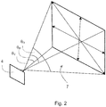
- the FOV of an exemplary image sensor unit 4 is illustrated in Fig. 2 . Any light incident on the image sensor unit 4 from within the FOV region 7 can be received by the image sensor 6 and used to form an image.
- the FOV 7 can be characterised by two angles, a horizontal FOV angle, ⁇ H , that is an angle measured in a horizontal plane (with respect to the image sensor 6) through which light can be detected by the image sensor unit 4, and a vertical FOV angle, ⁇ V , that is an angle measured in a vertical plane (with respect to the image sensor 6) through which light can be detected by the image sensor unit 4.
- ⁇ H will be different to ⁇ V (and in Fig. 2 ⁇ H is greater than ⁇ V , although this is merely an example).
- Fig. 2 shows a third angle ⁇ D , which is the angle measured in a diagonal plane through which light can be detected by the image sensor unit 4.
- the FOV in the diagonal plane ( ⁇ D ) represents the maximum FOV angle of the image sensor unit 4.
- the minimum FOV angle of the image sensor unit 4 is ⁇ V .
- the FOV of an image sensor unit 4 can be defined or controlled by optical components, such as lenses and apertures.
- the image sensor unit 4 may comprise one or more lenses for focussing or otherwise influencing light that is incident towards the image sensor unit 4.
- the image sensor unit 4 (or more generally the apparatus 2) can include an aperture plate that has an aperture of a defined size positioned in front of the image sensor unit 4 or image sensor 6 to restrict the field of view of the image sensor unit 4 or image sensor 6.
- the control unit 3 is provided to process or analyse the images obtained or generated by the apparatus 2, and in some implementations the control unit 3 can control the operation of apparatus 2, for example controlling or commanding the apparatus 2 to obtain one or more images.
- the control unit 3 can be configured to execute or perform the methods described herein.
- control unit 3 can be part of the apparatus 2, i.e. the image sensor unit 4 and the control unit 3 can be part of the same device, for example a handheld device, that can be placed close to or on to skin of a subject.
- control unit 3 can be connected or coupled to the apparatus 2 (and in particular the image sensor unit 4) in order to receive the images.
- control unit 3 can be in a separate device to the apparatus 2.
- the apparatus 2 can be a handheld device that can be placed close to or on to the skin of a subject, and the control unit 3 can be part of a separate, second, device, for example a smartphone, tablet computer, laptop, desktop computer, server, etc.
- the control unit 3 may execute an application (app) in order to analyse the obtained images to determine the one or more skin properties.
- the system 1 can further comprise interface circuitry (not shown in Fig. 1 ) for enabling a data connection to and/or data exchange between the control unit 3 and the apparatus 2.
- the connection may be direct or indirect (e.g.
- the interface circuitry can enable a connection between the apparatus 2 and control unit 3 via a network, such as the Internet, via any desirable wired or wireless communication protocol or protocols.
- the interface circuitry can operate using WiFi, Bluetooth, Zigbee, or any cellular communication protocol (including but not limited to Global System for Mobile Communications (GSM), Universal Mobile Telecommunications System (UMTS), Long Term Evolution (LTE), LTE-Advanced, etc.).
- GSM Global System for Mobile Communications
- UMTS Universal Mobile Telecommunications System
- LTE Long Term Evolution
- LTE-Advanced etc.
- the control unit 3 and the apparatus 2 can have respective interface circuitry to enable a data connection or data exchange therebetween.
- the apparatus 2 can be in the form of, or part of, a personal care device, such as (but not limited to) a shaver, a skin cleansing device or a skin treatment device.
- a personal care device such as (but not limited to) a shaver, a skin cleansing device or a skin treatment device.
- the system 1 can comprise interface circuitry for enabling a data connection or data exchange with other devices, including any one or more of servers, databases, and user devices.
- This interface circuitry can be used to communicate determined measurements of skin properties from the system 1 to another device, for example a server or data storage facility.
- the control unit 3 can be implemented in numerous ways, with software and/or hardware, to perform the various functions described herein.
- the control unit 3 may comprise one or more microprocessors or digital signal processor (DSPs) that may be programmed using software or computer program code to perform the required functions and/or to control components of the control unit 3 to effect the required functions.
- DSPs digital signal processor
- the control unit 3 may be implemented as a combination of dedicated hardware to perform some functions (e.g. amplifiers, pre-amplifiers, analog-to-digital convertors (ADCs) and/or digital-to-analog convertors (DACs)) and a processor (e.g., one or more programmed microprocessors, controllers, DSPs and associated circuitry) to perform other functions. Examples of components that may be employed in various embodiments of the present disclosure include, but are not limited to, conventional microprocessors, DSPs, application specific integrated circuits (ASICs), and field-programmable gate arrays (FPGAs).
- the control unit 3 may comprise or be connected to a memory unit (not shown in Fig. 1 ) that can store data, information and/or signals for use by the control unit 3 in controlling the operation of the apparatus 2 and/or in executing or performing the methods described herein.
- the memory unit stores computer-readable code that can be executed by the control unit 3 so that the control unit 3 performs one or more functions, including the methods described herein.
- the memory unit can comprise any type of non-transitory machine-readable medium, such as cache or system memory including volatile and non-volatile computer memory such as random access memory (RAM) static RAM (SRAM), dynamic RAM (DRAM), read-only memory (ROM), programmable ROM (PROM), erasable PROM (EPROM) and electrically erasable PROM (EEPROM), implemented in the form of a memory chip, an optical disk (such as a compact disc (CD), a digital versatile disc (DVD) or a Blu-Ray disc), a hard disk, a tape storage solution, or a solid state device, including a memory stick, a solid state drive (SSD), a memory card, etc.
- RAM random access memory
- SRAM static RAM
- DRAM dynamic RAM
- ROM read-only memory
- PROM programmable ROM
- EPROM erasable PROM
- EEPROM electrically erasable PROM
- EEPROM electrically erasable PROM
- the apparatus 2 further comprises a first light arrangement 10 that comprises one or more light sources 12 and a second light arrangement 14 that comprises one or more light sources 16.
- a first light arrangement 10 that comprises one or more light sources 12
- a second light arrangement 14 that comprises one or more light sources 16.
- the light source(s) 12 in the first light arrangement 10 and the light source(s) 16 in the second light arrangement 14 are spaced different distances from the image sensor unit 4 to provide appropriate lighting conditions for measuring respective skin properties. The spacing of the light sources 12, 16 is described in more detail below.
- Each of the light source(s) 12 in the first light arrangement 10 and the light source(s) 16 in the second light arrangement 14 are for emitting light towards the skin of a subject when the apparatus 2 is placed on or close to a subject, thereby illuminating the skin of the subject.
- the first light arrangement 10 and second light arrangement 14 are for illuminating an area of skin of the subject within the field of view of the image sensor unit 4.
- Each of the light sources 12, 16 can be the same type of light source, or one or more of the light sources 12, 16 can be different from the other light sources 12, 16.
- a light source 12, 16 may be a light emitting diode (LED), a resonant cavity light emitting diode (RCLED), a vertical cavity surface emitting laser (VCSELs), an edge emitting laser, or any other suitable type of semiconductor light source.
- a light source 12, 16 can be, for example, an organic light emitting diode (OLED), a passive-matrix OLED (PMOLED), an active-matrix OLED (AMOLED), or any other organic material based light source.
- a light source 12, 16 can be, for example, a solid state light source. Those skilled in the art will be aware of other types of light source that could be used in the apparatus 2.
- each of the first light arrangement 10 and the second light arrangement 14 may comprise one light source 12, 16, preferably each of the first light arrangement 10 and the second light arrangement 14 comprise a plurality of light sources 12, 16.
- the first light arrangement 10 comprises two light sources 12, but in other embodiments the first light arrangement 10 comprises three, four, or more than four, light sources 12.
- the second light arrangement 14 comprises two light sources 16, but in other embodiments the second light arrangement 14 comprises three, four, or more than four, light sources 16.
- the first light arrangement 10 has the same number of light sources as the second light arrangement 14, but in other embodiments the first light arrangement 10 has a different number of light sources to the second light arrangement 14.
- the light sources 12, 16 in each arrangement may be arranged around the image sensor unit 4 to provide uniform, or generally uniform, illumination to the skin.
- the light sources 12, 16 for a particular arrangement 10, 14, may be provided in a ring around (e.g. equidistant or substantially equidistant from) the image sensor unit 4 to provide uniform illumination to the skin.
- the light sources in the arrangement may be configured to operate together, i.e. each of the light sources in the arrangement can emit light at the same time. That is, the control unit 3 can be configured to control the light sources in the arrangement so that they all emit light at the same time.
- the light sources in the arrangement may be configured to operate sequentially or individually, i.e. each of the light sources in the arrangement can be controlled by the control unit 3 to emit light one at a time, with respective images being obtained when each of the light sources is emitting light.
- a light arrangement may be controllable to switch between a mode in which all of the light sources are emitting light at the same time, and a mode in which the light sources emit light one at a time. That is, the control unit 3 can be configured to selectively operate the light sources in an arrangement in a first mode so that they all emit light at the same time and a second mode so that they emit light individually.
- the light sources 12, 16 in the first light arrangement 10 and the second light arrangement 14 are configured to emit white light.
- any of the light sources 12, 16 in the first light arrangement 10 and the second light arrangement 14 can be configured to emit visible light, including but not limited to, white light, red light, green light and blue light.
- the colour of light emitted by the light sources 12, 16 in the first light arrangement 10 and the second light arrangement 14 may depend on the skin properties to be measured by the apparatus 2.
- the light source(s) 12 in the first light arrangement 10 can be configured to emit visible light of any colour (including white light).
- the light source(s) 16 in the second light arrangement 14 can be configured to emit visible light of any colour (including white light), ultraviolet (UV) light, and/or infrared (IR) light.
- the colour of the light emitted by the light sources 12, 16 in the first light arrangement 10 and/or the second light arrangement 14 can be controllable, for example according to a particular skin property to be measured.
- the light sources 12, 16 in the first light arrangement 10 and second light arrangement 14 can emit light that is unpolarised.
- a polariser or polarising filter can be provided for each light source(s) 16 in the second light arrangement 14 that acts to polarise the light emit by the light source(s) 16 in the second light arrangement 14 before it is incident on the skin of the subject.
- These polariser(s) or polarising filter(s) are referred to herein as second polariser(s) or second polarising filter(s), and polarises light passing through the second polariser or second polarising filter in a second polarising direction.
- the second polariser(s) or second polarising filter(s) can be a separate component to the light source(s) 16 in the second light arrangement 14, or they can be integral to the light source(s) 16 in the second light arrangement 14. In some embodiments where polariser(s) or polarising filter(s) are provided for the light source(s) 16 in the second light arrangement 14, the light source(s) 12 in the first light arrangement 10 do not have polariser(s) or polarising filter(s).
- the first polarising filter and the second polarising filter(s) for the light source(s) in the second light arrangement 14 can be 'crossed' so that most of the light from the light source(s) in the second light arrangement 14 is not incident on the image sensor unit 4 (i.e. only light from the light source(s) in the second light arrangement 14 whose angle of polarisation is altered by reflection from the skin of the subject is able to pass through the first polarising filter and reach the image sensor unit 4/image sensor 6).
- the first polarising filter can be arranged so that the first polarising direction is orthogonal to the second polarising direction of the second polarising filter(s).
- the apparatus 2 can further comprise a third light arrangement 18 that comprises one or more light sources 20.
- the third light arrangement 18 can be provided for measuring other skin properties that cannot be measured (or that cannot be measured as reliably) using the light source(s) 12 in the first light arrangement 10 and the light source(s) 16 in the second light arrangement 14.
- the third light arrangement 18 is provided where the light from the second light arrangement 14 is polarised using the second polarisers or second polarising filters.
- the light source(s) 20 in the third light arrangement 18 do not have polariser(s) or polarising filter(s).
- each of the light source(s) 20 in the third light arrangement 18 are for emitting light towards the skin of a subject when the apparatus 2 is placed on or close to a subject, thereby illuminating the skin of the subject.
- the third light arrangement 18 is for illuminating an area of skin of the subject within the field of view of the image sensor unit 4.
- the light source(s) 20 can be the same type of light source as the light sources 12, 16 in the first light arrangement 10 and the second light arrangement 14, or the light sources 20 can be different to the other light sources 12, 16.
- a light source 20 may be a LED, a RCLED, a VCSEL, an edge emitting laser, or any other suitable type of semiconductor light source.
- a light source 20 can be, for example, an OLED, a PMOLED, an AMOLED, or any other organic material based light source.
- a light source 20 can be, for example, a solid state light source. Those skilled in the art will be aware of other types of light source that could be used in the apparatus 2.
- the third light arrangement 18 may comprise one light source 20, preferably the third light arrangement 18 comprises a plurality of light sources 20. In some embodiments, the third light arrangement 18 comprises two light sources 20, but in other embodiments the third light arrangement 18 comprises three, four, or more than four, light sources 20. In some embodiments, the third light arrangement 18 has the same number of light sources as the first light arrangement 10 and/or the second light arrangement 14, but in other embodiments the third light arrangement 18 has a different number of light sources to the first light arrangement 10 and the second light arrangement 14. Where the third light arrangement 18 comprises multiple light sources 20, the light sources 20 in each arrangement may arranged around the image sensor unit 4 to provide uniform, or generally uniform, illumination to the skin. For example, the light sources 20 may be provided in a ring around (e.g.
- control unit 3 may be configured to control the light sources 20 in the third light arrangement 18 so that they emit light at the same time, and/or control the light sources 20 in the third light arrangement 18 so that they emit light sequentially or individually.
- the light source(s) 20 in the third light arrangement 18 are configured to emit white light. In some embodiments, any of the light source(s) 20 in the third light arrangement 18 can be configured to emit visible light, including but not limited to, white light, red light, green light and blue light. The colour of light emitted by the light source(s) 20 in the third light arrangement 18 may depend on the skin properties to be measured by the apparatus 2. In some embodiments, the light source(s) 20 in the third light arrangement 18 can be configured to emit visible light of any colour (including white light), infrared (IR) light, and/or ultraviolet (UV) light.
- any colour including white light
- IR infrared
- UV ultraviolet
- the first light arrangement 10, the second light arrangement 14 and (if present) the third light arrangement 18 can be controlled by the control unit 3.
- the control unit 3 can control the activation or deactivation of a particular light arrangement or particular light source(s) in a light arrangement according to a particular skin property to be measured.
- the apparatus 2 can comprise a user interface (not shown in Fig. 1 ) that includes one or more components that enables a user of apparatus 2 (e.g. the subject) to input information, data and/or commands into the apparatus 2, and/or enables the apparatus 2 to output information or data to the user of the apparatus 2.
- the user interface can comprise any suitable input component(s), including but not limited to a keyboard, keypad, one or more buttons, switches or dials, a mouse, a track pad, a touchscreen, a stylus, a camera, a microphone, etc.
- the user interface can comprise any suitable output component(s), including but not limited to a display screen, one or more lights or light elements, one or more loudspeakers, a vibrating element, etc.
- the apparatus 2 can also determine a skin property such as hydration level, and the apparatus 2 can further comprise an impedance sensor for measuring the impedance of the skin.
- the impedance sensor may be positioned so that it measures the impedance of a part of the skin that is different to the skin sample, e.g. skin that is adjacent to the skin sample.
- the impedance sensor can comprise two or more electrodes that are to be placed in contact with the skin, with the impedance being measured by applying a current to the skin through the electrodes.
- an apparatus 2 may include additional components to those shown in Fig. 1 .
- the apparatus 2 may also include a power supply, such as a battery, or components for enabling the apparatus 2 to be connected to a mains power supply.
- the light source(s) 12 in the first light arrangement 10 the light source(s) 16 in the second light arrangement 14 and the light source(s) 20 in the third light arrangement 18 (if present) are spaced different distances from the image sensor unit 4 to provide appropriate lighting conditions for measuring respective skin properties.
- some skin properties such as gloss and oiliness
- Skin texture can also be measured using an image acquired when light is specularly reflected from the skin sample towards the image sensor unit 4.
- the acquired image can be generated using diffuse light, and so light should not be specularly reflected from the skin sample towards the image sensor unit 4 (and therefore the acquired image will not show a bright spot or 'hotspot' corresponding to the light source).
- Skin texture can also be measured using an image acquired using diffuse light.
- the light incident on the skin should be polarised, and the apparatus 2 should include the first polariser arranged orthogonally to the polarisation of the light incident on the skin.
- embodiments provide that the light source(s) 12 in the first light arrangement 10 are arranged with respect to the image sensor unit 4 so that light emitted by the light source(s) 12 in the first light arrangement 10 towards a skin sample at some predetermined or desired working distance from the image sensor unit 4 is specularly reflected by the skin sample and incident on the image sensor unit 4.
- specular reflection(s) will be visible in the image or images obtained by the image sensor unit 4.
- an image or images acquired when the first light arrangement 10 is used to illuminate the skin sample can be processed or analysed by the control unit 3 to determine skin properties such as gloss, oiliness and texture.
- Embodiments also provide that the light source(s) in the second light arrangement 14 are arranged with respect to the image sensor unit 4 so that light emitted by the light source(s) 16 in the second light arrangement 14 towards the skin sample at the predetermined or desired working distance from the image sensor unit 4 that is specularly reflected by the skin sample is not incident on the image sensor unit 4. Thus, specular reflection(s) will not be visible in the image or images obtained by the image sensor unit 4.
- an image or images acquired when the second light arrangement 14 is used to illuminate the skin sample can be processed or analysed by the control unit 3 to determine skin properties such as skin colour, redness, skin pigmentation, the presence of spots (such as black heads and white heads), the presence of hairs and skin texture.
- FIG. 3 A cross-section through an apparatus 2 is shown in Fig. 3 to illustrate an exemplary arrangement of the first light arrangement 10 and second light arrangement 14 with respect to an image sensor unit 4 according to various embodiments.
- the first light arrangement 10, second light arrangement 14 and the image sensor unit 4 are in generally the same plane.
- Fig. 3 shows an apparatus 2 placed close to the skin 30 of a subject, and in particular the apparatus 2 is placed close to the skin 30 of the subject so that the image sensor unit 4 and the light source(s) 12, 16 of the first light arrangement 10 and the second light arrangement 14 are spaced from the skin 30 by a working distance D.
- the apparatus 2 may be shaped or configured so that the image sensor unit 4 and the light source(s) 12, 16 of the first light arrangement 10 and the second light arrangement 14 can be reliably spaced from the skin 30 by the working distance D.
- the apparatus 2 may comprise a spacer that is on or part of a housing of the apparatus 2, that extends beyond the image sensor unit 4, the first light arrangement 10 and the second light arrangement 14 so that the spacer can be placed in contact with the skin 30, thereby spacing the components 4, 10, 14 the distance D from the skin 30.
- the working distance D can be between 20 millimetres (mm) and 80 mm, although those skilled in the art will appreciate that the working distance D may be less than 20 mm or greater than 80 mm.
- the image sensor unit 4 has a field of view 7 defined by one or more angles, and in Fig. 3 this angle is simply denoted angle ⁇ .
- angle ⁇ may correspond to any of the angles between ⁇ V and ⁇ D in Fig. 2 (inclusive), noting that the vertical FOV angle ⁇ V is the smallest FOV angle in Fig. 2 and the diagonal FOV angle ⁇ D is the largest FOV angle in Fig. 2 .
- the boundary of the FOV 7 of the image sensor unit 4 is shown by dashed lines 32.
- the FOV 7 of the image sensor unit 4 is able to acquire images of a part of the skin 30, and this is shown as skin sample 34.
- skin sample 34 refers to an area of skin 30 of the subject within the FOV of the image sensor unit 4 when the skin 30 is spaced the predetermined working distance D from the image sensor unit 4.
- the skin sample 34 has a width denoted wss, which is given by 2*D*tan( ⁇ /2).
- Two light sources 12 for the first light arrangement 10 are shown in Fig. 3 .
- the light sources 12 are spaced from the image sensor unit 4 (as measured in a plane that is parallel to the plane of the skin sample 34) by a distance that is equal to or less than the width w SS of the skin sample 34.
- light emitted by these light sources 12 can be specularly reflected by the skin sample 30 towards the image sensor unit 4, and the image sensor unit 4 can produce an image from this specularly reflected light.
- An exemplary light ray 36 from one of the light sources 12 being specularly reflected by the skin sample 34 towards the image sensor unit 4 is shown in Fig. 3 .
- Two light sources 16 for the second light arrangement 14 are also shown in Fig. 3 .
- the light sources 16 are spaced from the image sensor unit 4 (as measured in the plane that is parallel to the plane of the skin sample 34) by a distance that is more than the width w SS of the skin sample 34.
- light emitted by these light sources 16 that is specularly reflected by the skin sample 34 will not be incident on the image sensor unit 4. Instead, only diffuse light provided by the light sources 16 will be incident on the image sensor unit 4 and contribute to an image of the skin sample 34.
- An exemplary light ray 38 from one of the light sources 16 being specularly reflected by the skin sample 34 away from the image sensor unit 4 is shown in Fig. 3 . It will be appreciated that by definition of the FOV 7 of the image sensor unit 4, any light from the light sources 16 that is specularly reflected by skin 30 that is not part of skin sample 34 cannot be detected by the image sensor unit 4.
- the light source(s) 20 forming the third light arrangement 18 can be spaced from the image sensor unit 4 (as measured in the plane that is parallel to the plane of the skin sample 34) by a distance that is more than the width wss of the skin sample 34.
- the light source(s) 20 forming the third light arrangement 18 can be spaced from the image sensor unit 4 by a similar distance to the light source(s) 16 forming the second light arrangement 14.
- the light source(s) 20 forming the third light arrangement 18 can be spaced from the image sensor unit 4 by a greater distance than the light source(s) 16 forming the second light arrangement 14.
- the light source(s) 20 forming the third light arrangement 18 can be spaced from the image sensor unit 4 by a smaller distance than the light source(s) 16 forming the second light arrangement 14 (although still greater than wss).
- the exemplary spacing of the light sources 12, 16 described above is based on the light sources 12, 16 being in the same plane as each other, and in the same plane as the image sensor unit 4. If the light sources 12, 16 are in a different plane to the image sensor unit 4 (for example if the light sources 12, 16 are a distance from the skin 30 that is different to the distance from the image sensor unit 4 to the skin 30), then the requirements on the distance between the light sources 12, 16 and the image sensor unit 4 will need to be adjusted accordingly in order to provide that light from the first light arrangement 10 is specularly reflected by the skin sample 34 to the image sensor unit 4 and light from the second light arrangement 14 that is specularly reflected by the skin sample 34 is not incident on the image sensor unit 4.
- An exemplary embodiment where the light arrangements are positioned between the skin 30 and the image sensor unit 4 is described below with reference to Figs. 8 and 9 .
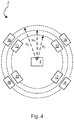
- Fig. 4 shows a front view of an exemplary apparatus 2.
- the light sources and the image sensor 4 are in the same plane, or generally in the same plane.
- Fig. 4 shows the apparatus 2 from the point of view of the skin sample 34.
- each of the first light arrangement 10 and the second light arrangement 14 comprise four light sources 12, 16 that are arranged in respective rings around the image sensor unit 4, with the light sources 12, 16 each being offset diagonally with respect to the image sensor unit 4.
- the light sources 12, 16 in each ring are spatially distributed around the optical axis of the image sensor unit 4 (i.e. an axis that extends perpendicularly from the centre of the plane of the image sensor unit 4), so that the skin 30 is illuminated from different directions.
- the light sources 12, 16 in each ring are generally evenly spaced with respect to each other around the image sensor unit 4, although other configurations are possible.
- the light sources 12 in the first light arrangement 10 are each spaced from the image sensor unit 4 (and specifically spaced from the optical axis of the image sensor unit 4) by a distance R 1 that is equal to or less than wss (which in this exemplary arrangement is the width of the diagonal dimension of the FOV 7 since the light sources 12, 16 in both arrangements are offset diagonally from the image sensor unit 4), and the light sources 16 in the second light arrangement 14 are each spaced from the image sensor unit 4 (and specifically spaced from the optical axis of the image sensor unit 4) by a distance R 2 that is greater than wss.
- R 1 that is equal to or less than wss
- R 2 that is greater than wss.
- Fig. 5 shows a front view of another exemplary apparatus 2.
- the light sources and the image sensor 4 are again in the same plane, or generally in the same plane.
- the apparatus 2 in Fig. 5 corresponds to the apparatus 2 in Fig. 4 , with the addition of a third light arrangement 18 comprising four light sources 20, with each light source 20 being offset diagonally from the image sensor unit 4.
- the light sources 20 are spatially distributed around the optical axis of the image sensor unit 4 so that the skin 30 is illuminated from different directions.
- a first polariser is provided to polarise the light incident on the image sensor unit 4, and each of the four light sources 16 in the second light arrangement 14 have respective second polarisers (that are arranged orthogonally to the first polariser).
- the third light arrangement 18 is arranged in a respective ring around the image sensor unit 4, with the light sources 20 in the third light arrangement 18 being generally evenly spaced with respect to each other around the image sensor unit 4, and being spaced from the image sensor unit 4 (and specifically spaced from the optical axis of the image sensor unit 4) by a distance R 3 that is greater than R 2 (and therefore greater than wss).
- the light sources 20 in the third light arrangement 18 are each aligned in a radial direction with a respective one of the four light sources 12, 16 of the first light arrangement 10 and the second light arrangement 14, but it will be appreciated that this is purely exemplary, and other configurations are possible.
- the distance R 1 between the light sources 12 of the first light arrangement 10 is at least 4 millimetres (mm), or another distance in the range of 3-7 mm. In some embodiments, the distance R 2 between the light sources 16 of the second light arrangement 14 is at least 8 mm, or another distance in the range of 7-15 mm. In some embodiments, the distance R 3 between the light sources 20 of the third light arrangement 18 is at least 8 mm, or another distance in the range of 7-15 mm.
- the distance R 2 between the light sources 16 of the second light arrangement 14 is at least 8 mm, or another distance in the range of 7-11 mm and the distance R 3 between the light sources 20 of the third light arrangement 18 is at least 12 mm, or another distance in the range of 11-15 mm.
- the light sources 12 of the first light arrangement 10 should be less than 9 mm from the image sensor unit 4, and this provides an angle of incidence of the light from the first light arrangement 10 from the skin sample 34 on to the image sensor unit 4 (as measured with respect to an optical axis of the image sensor unit 4) of no more than 8.5° (based on the smallest dimension of the field of view of 9 mm), and in a particular embodiment the light sources 12 of the first light arrangement 10 are spaced from the image sensor unit 4 to provide an angle of incidence of light of 5.5°.
- the angle of incidence should therefore be at least 8.5° for light emitted by the light source(s) 16 in the second light arrangement 14 and/or the light source(s) 20 in the third light arrangement 18 (where those light sources 16 are offset with respect to the shortest dimension of the image sensor unit 4) and at least 14° for light emitted by the light source(s) 16 in the second light arrangement 14 and/or the light source(s) 20 in the third light arrangement 18 if those light sources are offset diagonally from the image sensor 6 (given that the largest dimension of the field of view is 15 mm - the length from corner to corner of the skin sample 34 in the FOV).
- the light sources 12 of the first light arrangement 10 should be less than 7.5 mm from the image sensor unit 4, and this provides an angle of incidence of the light from the first light arrangement 10 from the skin sample 34 on to the image sensor unit 4 (as measured with respect to an optical axis of the image sensor unit 4) of no more than 20° (based on the smallest dimension of the field of view of 7.5 mm).
- the angle of incidence should therefore be at least 20° for light emitted by the light source(s) 16 in the second light arrangement 14 and/or the light source(s) 20 in the third light arrangement 18 (where those light sources 16, 20 are offset with respect to the shortest dimension of the image sensor unit 4) and at least 32° for light emitted by the light source(s) 16 in the second light arrangement 14 and/or the light source(s) 20 in the third light arrangement 18 if those light sources are offset diagonally from the image sensor 6 (given that the largest dimension of the field of view is 12.5 mm - the length from corner to corner of the skin sample 34 in the FOV).
- the light source(s) 12 in the first light arrangement 10 are spaced from the image sensor unit 6 by a distance that is equal to or less than 2 ⁇ D ⁇ tan ⁇ min / 2 where D is the predetermined working distance, and ⁇ min is a smallest FOV angle of the image sensor unit 4.
- ⁇ min is ⁇ V . It will be appreciated that this applies regardless of the position of a light source(s) 12 around the image sensor unit 4 (since it uses the smallest FOV angle).
- ⁇ min can be substituted for ⁇ D to determine the maximum spacing of the light source(s) 12 in the first light arrangement 10 from the image sensor unit 4.
- the light source(s) 16 in the second light arrangement 14 and light source(s) 20 in the third light arrangement 18 are spaced from the image sensor unit 4 by a distance that is greater than: 2 ⁇ D ⁇ tan ⁇ max / 2 where D is the predetermined working distance, and ⁇ max is a largest FOV angle of the image sensor unit 4. In the example shown in Fig. 2 ⁇ max is ⁇ D . It will be appreciated that this applies regardless of the position of the light source(s) 16, 20 around the image sensor unit 4 (since it uses the largest FOV angle). However, if the light source(s) 16, 20 in the second light arrangement 14 and the third light arrangement 18 are only positioned with respect to a shorter dimension of the FOV of the image sensor unit 4 (e.g.
- ⁇ msx can be substituted for ⁇ V in the case of vertical position or ⁇ H in the case of horizontal position to determine the minimum spacing of the light source(s) 16 in the second light arrangement 14 and the light source(s) 20 in the third light arrangement 18 from the image sensor unit 4.
- the lighting or illumination conditions required to measure a particular skin property varies depending on the skin property itself.
- These lighting or illumination conditions include whether there is specular reflection from the relevant light arrangement 10, 14, 18 in the FOV 7 of the image sensor unit 4, the polarisation of light incident on the image sensor unit 4 and the colour of the emitted light.
- the conditions can also relate to the light source-image sensor distance, the angle of incidence, the emitted light divergence angle, the polarisation of the light incident on the image sensor 6, the number of light sources, the homogeneity of illumination, whether there should be hotspots (specular reflection) in the field of view of the image sensor unit 4, whether the light sources should be operated sequentially (individually) or simultaneously, etc.
- Table 1 below summarises several lighting or illumination conditions that can be used to measure various different skin properties. It will be appreciated that the information contained in Table 1 is merely exemplary, and variations to one or more of the lighting or illumination conditions is possible.
- parallel or sequential refers to whether the light sources in a light arrangement should be operated together (i.e. parallel) or one at a time (i.e. sequentially or individually).
- multiple images may be required to reliably determine the skin parameter, with each of the multiple images being obtained when a different one of the light sources in the light arrangement is being operated.
- a measure for the skin property e.g. gloss or oiliness
- control unit 3 can selectively control each of the light sources 12 in the first light arrangement 10 to individually illuminate the skin of the subject, and the image sensor unit 4 can acquire a respective image when each of the light sources 12 is active.
- the control unit 3 can process each of these images to determine a respective initial value for a skin property (e.g. gloss, oiliness, shine and/or texture), and then combine the initial values (e.g. by averaging, such as the mean, mode or median) to determine a value for the skin property.
- a skin property e.g. gloss, oiliness, shine and/or texture
- shine can be determined as the amount (e.g. intensity) of specular reflection from the skin sample 34.
- the skin parameter oiliness can represent how oily the skin sample appears, and is influenced by the shine of the skin, the sweatiness of the skin, and the amount of sebum on the skin. Oiliness can be determined from each image based on one or more parameters, including the amount (e.g. intensity) of reflection, the distribution, granularity and/or intensity of specular reflection from the skin sample 34, a roughness or texture of the skin, principal component analysis of the image, a histogram shape encoding of texture maps, and contrast in the image.
- the polarisation column indicates whether a polariser is required at a light source (L), at the image sensor unit 4 (S) or both (S+L).
- the light source divergence (otherwise referred to as the level of collimation of the emitted light) indicates the desired divergence of the light source used to measure the particular skin property.
- the light source(s) 12 in the first light arrangement 10 preferably have a wide divergence (e.g. the light source(s) 12 emit light at the same or similar intensity across a wide angle (or even in all directions) and the light source(s) in the second light arrangement 14 should have a narrow or wide divergence, depending on the skin property to be measured.
- a light source that can provide a narrow divergence (i.e. only emitting light across a narrow angle) is a laser-based light source or a light source with a lens arrangement to provide collimated light.
- the light arrangement can comprise multiple light sources that have different divergence properties (e.g. LEDs with different collimation angles, or light sources with different lens arrangements), and the appropriate light source(s) can be operated when a particular skin property is to be measured.
- the RGB detector channel refers to a capture mode of the image sensor 6.
- the image sensor 6 can be controlled to capture images in colour (i.e. RGB mode), or in one or more colour channels (i.e. in red (R), green (G) and/or blue (B) mode).
- the skin parameter redness can be measured using the second light arrangement 14, with all light sources 16 being operated at the same time to evenly illuminate the skin sample 34.
- the redness can be determined based on the redness values of pixels in the acquired image (e.g. the value of the R component for each pixel). For example the redness can be determined as the average of the redness values for all of the pixels in the acquired image.
- a measure of colour contrast can also be used to determine the redness.
- the skin parameter pores and/or blackheads (which can be considered as clogged or blocked pores) can be measured using the third light arrangement 18, with all light sources 20 being operated at the same time to evenly illuminate the skin sample 34.
- pores and blackheads can be identified by differences in contrast in the acquired image.
- Image analysis (for example using a 'machine learning' trained algorithm) can be used to identify pores/blackheads and quantify their number and/or their size. Image analysis can also distinguish between pores and blackheads.
- Fig. 6 shows a front view of another exemplary apparatus 2.
- This apparatus 2 generally corresponds to the apparatus 2 shown in Fig. 5 , although the light sources 16 in the second light arrangement 14 are in different positions with respect to the image sensor unit 4 (i.e. a different spatial distribution).
- the light sources 12, 20 for the first light arrangement 10 and the third light arrangement 18 are offset diagonally with respect to the orientation of the image sensor unit 4, but the light sources 16 for the second light arrangement 14 are offset vertically and horizontally with respect to the orientation of the image sensor unit 4.
- the light sources 16 for the second light arrangement 14 and the light sources 20 for the third light arrangement 18 are generally the same distance from the optical axis of the image sensor unit 4.
- the light sources 16 for the second light arrangement 14 offset vertically with respect to the image sensor unit 4 can be positioned closer to the optical axis of the image sensor unit 4 than the light sources 16 for the second light arrangement 14 that are offset horizontally with respect to the image sensor unit 4. This positioning can enable the apparatus 2 to be more compact.
- Fig. 7 shows a front view of another exemplary apparatus 2.
- This apparatus 2 generally corresponds to the apparatus 2 shown in Fig. 5 , although the third light arrangement 18 comprises eight light sources 20 arranged generally equidistant from a midpoint of the image sensor unit 4.
- the light sources 20 are vertically, horizontally and diagonally offset with respect to the orientation of the image sensor unit 4.
- the light sources 20 for the third light arrangement 18 are further from the image sensor unit 4 than the light sources 16 for the second light arrangement 14.
- This increase in the distance from the image sensor unit 4 provides a shallower angle of illumination and therefore a larger shadowing effect on the skin, making the structure (e.g. texture) more visible in an acquired image.
- the light sources 20 in the third light arrangement 18 can be different types, for example four of the light sources 20 can emit visible light, and the other four light sources 20 can emit UV light (since the UV light can enable a higher resolution for the structure measurement).
- Fig. 8 shows a front view of another exemplary apparatus 2
- Fig. 9 shows a cross-section through line A-A' in Fig. 8
- This exemplary apparatus 2 includes first, second and third light arrangements 10, 14, 18.
- a first polariser is provided to polarise the light incident on the image sensor unit 4, and second polarisers are provided to polarise the light emitted by the light sources 16 in the second light arrangement 14.
- the second polarisers are crossed with respect to the first polariser as described above.
- the light arrangements 10, 14, 18 are arranged in a plane that is between the image sensor unit 4 and the skin 30. That is, the image sensor unit 4 is spaced the predetermined working distance D from the skin 30 as in the earlier embodiments, but the light arrangements 10, 14, 18 are positioned less than distance D to the skin 30.
- the distance between the light arrangements 10, 14, 18 and the skin is denoted D LA- >s and the distance between the image sensor unit and the light arrangements 10, 14, 18 is denoted D ISU->LA .
- the apparatus 2 can be made more compact, as the light sources can be closer to the optical axis of the image sensor unit 4 while achieving the specular or non-specular illumination of the skin sample as appropriate for the particular light arrangement.
- the light sources for the light arrangements 10, 14, 18 are disposed on a circuit board 40, and the circuit board 40 has an aperture or hole 42 through which the image sensor unit 4 is able to view the skin sample 34.
- the light sources of the light arrangements 10, 14, 18 are arranged around the aperture 42.
- the field of view of the image sensor unit 4 (as represented by lines 32) is such that it is narrower than the aperture 42, but in other embodiments, the aperture 42 could help define the size of the skin sample visible to the image sensor unit 4 through the aperture 42.
- Fig. 8 shows the apparatus 2 from the point of view of the skin sample 34.
- Fig. 8 also shows an exemplary outline of the skin sample 34, which has width wss and length lss.
- each of the first light arrangement 10, the second light arrangement 14 and the third light arrangement 18 comprise four light sources 12, 16, 20 that are arranged in respective rings around the image sensor unit 4, with the light sources 12, 16 each being offset diagonally with respect to the image sensor unit 4.
- the light sources 20 of the third light arrangement 18 are offset vertically and horizontally with respect to the orientation of the image sensor unit 4.
- the light sources 12, 16, 20 in each ring are spatially distributed around the optical axis of the image sensor unit 4, so that the skin 30 is illuminated from different directions.
- the optical axis of the image sensor unit 4 is illustrated by line 44 in Fig. 9 .
- the light sources 12, 16 in each ring are generally evenly spaced with respect to each other around the image sensor unit 4, although other configurations/spatial distributions are possible.
- the light sources 12 in the first light arrangement 10 are each spaced from the image sensor unit 4 (and specifically spaced from the optical axis of the image sensor unit 4) by a distance R 1 so that specular reflections of the light on the skin sample are incident on the image sensor unit 4.
- the light sources 16 in the second light arrangement 14 and two of the light sources 20 of the third light arrangement 18 are each spaced from the image sensor unit 4 (and specifically spaced from the optical axis of the image sensor unit 4) by a distance R 2 .
- R 2 is greater than R 1 so that specular reflections on the skin sample of the light from these light sources is not incident on the image sensor unit 4.
- the other two light sources 20 in the third light arrangement 18 are spaced from the optical axis of the image sensor unit 4 by a distance R 3 , which in this embodiment is between R 1 and R 3 , so that specular reflections on the skin sample of the light from these light sources is not incident on the image sensor unit 4.
- R 3 which in this embodiment is between R 1 and R 3 , so that specular reflections on the skin sample of the light from these light sources is not incident on the image sensor unit 4.
- all of the light sources 16, 20 of the second and third light arrangements 14, 18 can be spaced the same distance from the optical axis of the image sensor unit 4.
- D LA->S is 24 mm, or another distance in the range 20-60 mm
- D ISU->LA is 34 mm or 34.7 mm, or another distance in the range of 10-40 mm.
- the predetermined working distance D can be 58 mm or 58.7 mm, or another distance in the range 30-100 mm.
- the distance R 1 can be 5.5 mm, or another distance in the range 1-6 mm.
- the distance R 2 can be 8.75 mm or about 9 mm.
- the distance R 3 can be 7 mm. Alternatively, R 2 and/or R 3 can be any distance greater than 7 mm.
- the first light arrangement 10 can be used to obtain images that are processed to determine a value for the oiliness, shine and/or texture of the skin sample 34
- the second light arrangement 14 can be used to obtain one or more images that are processed to determine a value for the redness, spots (identified by their colour), colour and/or pigmentation of the skin sample 34
- the third light arrangement 18 can be used to obtain one or more images that are processed to determine a value for the pores and blackheads of the skin sample 34.
- FIG. 10 A method of operating the system 1 to determine one or more properties of the skin 30 of a subject is illustrated in Fig. 10 . As noted below, various steps of the method can be performed by the control unit 3 in conjunction with the image sensor unit 4, the first light arrangement 10 and the second light arrangement 14, and, where present, the third light arrangement 18.
- step 101 the skin of the subject is illuminated using the first light arrangement 10.
- This step can comprise the control unit 3 controlling the light source(s) 12 in the first light arrangement 10 to emit light.
- this step can comprise the skin being illuminated by all of the light sources 12 at once, or the skin being selectively illuminated by the light sources 12 one at a time.
- a first image of a skin sample 34 is generated using the image sensor unit 4.
- the first image is generated while the first light arrangement 10 is illuminating the skin 30.
- the skin sample 34 corresponds to an area of the skin 30 that is within the FOV of the image sensor unit 4 when the skin 30 is spaced a predetermined working distance D from the image sensor unit 4.
- step 105 the skin of the subject is illuminated using the second light arrangement 14.
- This step can comprise the control unit 3 controlling the light source(s) 16 in the second light arrangement 14 to emit light.
- this step can comprise the skin being illuminated by all of the light sources 16 at once, or the skin being illuminated by the light sources 16 one at a time.
- step 107 a second image of skin sample 34 is generated using the image sensor unit 4.
- the second image is generated while the second light arrangement 14 is illuminating the skin 30.
- step 109 the first image and the second image are processed by the control unit 3 to determine one or more properties of the skin of the subject.
- the skin property to be determined depends on the light arrangement used to illuminate the skin sample 34.
- the method is for determining values of multiple skin properties, with a first skin property being determined from images obtained when the skin sample is illuminated with light from the first light arrangement 10 and a second skin property being determined from images obtained when the skin sample is illuminated with light from the second light arrangement 14.
- the first light arrangement 10 comprises multiple light sources 12 and the control unit 3 controls the light sources 12 to illuminate the skin sample individually (i.e. one at a time), and the image sensor unit 4 obtains a respective image when each of the light sources 12 is active. These images are referred to as 'first' images.
- the second light arrangement 14 includes one or more light sources 16, and the image sensor unit 4 obtains one or more images when the light source or light sources 16 are active together. This or these images are referred to as 'second' images.
- the control unit 3 processes each first image to determine a respective initial value for the first skin property, and then combines the determined initial values to determine a value for the first skin property.
- the combination can be an average, e.g. mean, mode or median.
- the control unit 3 processes the one or more second images to determine a value for the second skin property.
- the control unit 3 can selectively control the third light arrangement 18 to illuminate the skin sample 34 when a third skin property is to be determined (e.g. pores or blackheads).
- a third skin property e.g. pores or blackheads
- the control unit 3 can control the light sources 20 to illuminate the skin sample 34 at the same time.
- the image sensor unit 4 obtains one or more images when the light sources 20 are active. This or these images are referred to as 'third' images.
- the control unit 3 processes the third image(s) to determine values for the third skin property.
- control unit 3 can control the impedance sensor to measure impedance, and process the impedance measurements to determine a measure of the hydration level of the skin.
- the first light arrangement 10 enables skin properties to be measured that require specular reflection in the image (e.g. oiliness, shine, gloss, texture)
- the second light arrangement 14, with cross-polarisation with the image sensor unit 4 enables skin properties relating to colour to be measured without specular disturbances (e.g. colour, colour variety, pigmentation, presence of hair)
- the third light arrangement 18 enables skin properties relating to the skin structure to be measured without specular disturbances (e.g. pores, blackheads).
- a computer program may be stored or distributed on a suitable medium, such as an optical storage medium or a solid-state medium supplied together with or as part of other hardware, but may also be distributed in other forms, such as via the Internet or other wired or wireless telecommunication systems. Any reference signs in the claims should not be construed as limiting the scope.
Claims (15)
- Ein System (1) zum Ermitteln der Werte für mehrere Eigenschaften der Haut eines Patienten, wobei das System Folgendes umfasst:eine Steuerungseinheit (3); undein Gerät (2)für das Abrufen von Bildern zum Ermitteln der Werte mehrerer Eigenschaften der Haut des Patienten, wobei das Gerät Folgendes umfasst:eine Bildsensoreinheit (4)zum Erzeugen eines Bilds einer Hautprobe, wobei die Hautprobe einem Bereich der Haut des Patienten innerhalb eines Bildfelds, FOV, der Bildsensoreinheit entspricht, wenn die Haut des Patienten einen vorab festgelegten Arbeitsabstand von der Bildsensoreinheit aufweist;eine erste Lichtanordnung (10), die mehrere Lichtquellen umfasst, die räumlich um die optische Achse der Bildsensoreinheit verteilt sind, um die Haut des Patienten aus den entsprechenden Richtungen zu beleuchten;eine zweite Lichtanordnung (14), die mehrere Lichtquellen zum Beleuchten der Haut des Patienten umfasst; undwobei die Lichtquellen der ersten Lichtanordnung einen Abstand zur optischen Achse der Bildsensoreinheit aufweisen und so angeordnet sind, dass das von den Lichtquellen der ersten Lichtanordnung emittierte und von der Hautprobe im vorab festgelegten Arbeitsabstand spiegelnd reflektierte Licht auf die Bildsensoreinheit fällt;wobei die mindestens eine Lichtquelle der zweiten Lichtanordnung einen Abstand zur optischen Achse der Bildsensoreinheit aufweist und so angeordnet ist, dass das von den Lichtquellen der zweiten Lichtanordnung emittierte und von der Hautprobe im vorab festgelegten Arbeitsabstand spiegelnd reflektierte Licht nicht auf die Bildsensoreinheit fällt;wobei die Steuerungseinheit folgende Schritte durchführt:selektives Steuern der einzelnen Lichtquellen der ersten Lichtanordnung, um die Haut des Patienten individuell zu beleuchten;Abrufen einer entsprechenden Anzahl erster Bilder von der Bildsensoreinheit, wobei die einzelnen ersten Bilder von der Bildsensoreinheit abgerufen werden, wenn die jeweilige Lichtquelle der ersten Lichtanordnung die Haut beleuchtet;Verarbeiten der einzelnen ersten Bilder, um den jeweiligen Anfangswert für eine erste Hauteigenschaft zu ermitteln, und Kombinieren der ermittelten Anfangswerte, um einen Wert für die erste Hauteigenschaft zu ermitteln;selektives Steuern der zweiten Lichtanordnung, um die Haut des Patienten zu beleuchten;Abrufen mindestens eines zweiten von der Bildsensoreinheit erzeugten Bilds, wobei die einzelnen zweiten Bilder von der Bildsensoreinheit abgerufen werden, wenn die zweite Lichtanordnung die Haut des Patienten beleuchtet; undVerarbeiten des mindestens einen abgerufenen zweiten Bilds, um einen Wert für mindestens eine zweite Hauteigenschaft zu ermitteln.
- Ein System gemäß Anspruch 1, wobei die Lichtquellen der ersten Lichtanordnung und die mindestens eine Lichtquelle der zweiten Lichtanordnung in einer Ebene angeordnet sind.
- Ein System gemäß Anspruch 1 oder 2, wobei die Lichtquellen der ersten Lichtanordnung und die mindestens eine Lichtquelle der zweiten Lichtanordnung einen Abstand zur Haut des Patienten aufweisen, der geringer ist, als der vorab festgelegte Arbeitsabstand.
- Ein System gemäß einem der vorhergehenden Ansprüche, wobei die zweite Lichtanordnung mehrere Lichtquellen umfasst.
- Ein System gemäß Anspruch 4, wobei die Steuerungseinheit die Lichtquellen der zweiten Lichtanordnung selektiv so steuert, dass sie die Haut des Patienten gleichzeitig beleuchten.
- Ein System gemäß einem der Ansprüche 1 bis 5, wobei es sich bei der ersten Hauteigenschaft um die Fettigkeit handelt und die Steuereinheit die einzelnen ersten Bilder verarbeitet, um einen jeweiligen Anfangswert für die Fettigkeit zu ermitteln. Dies erfolgt beruhend auf mindestens einem der folgenden Parameter: Umfang der Spiegelreflexion von der Hautprobe, Verteilung, Granularität und/oder Intensität der Spiegelreflexion von der Hautprobe, Rauheit oder Textur der Haut, Hauptkomponentenanalyse des Bilds, Histogramm-Formcodierung der Texturkarten und Kontrast des Bilds.
- Ein System gemäß einem der Ansprüche 1 bis 8, wobei das Gerät zudem Folgendes umfasst:
einen ersten Polarisierungsfilter, der in Bezug auf die Bildsensoreinheit so angeordnet ist, dass der Polarisierungsfilter das auf die Bildsensoreinheit einfallende Licht polarisiert. - Ein System gemäß Anspruch 7, wobei das Gerät zudem Folgendes umfasst:einen entsprechenden zweiten Polarisierungsfilter für die einzelnen Lichtquellen der zweiten Lichtanordnung, der zum Polarisieren des von der Lichtquelle der zweiten Lichtanordnung emittierten Lichts dient,wobei die Polarisierungsrichtung des zweiten Polarisierungsfilters orthogonal zur Polarisierungsrichtung des ersten Polarisierungsfilters verläuft.
- Ein System gemäß Anspruch 8, wobei das Gerät zudem Folgendes umfasst:eine dritte Lichtanordnung, die mehrere Lichtquellen zum Beleuchten der Haut des Patienten umfasst;wobei die mindestens eine Lichtquelle der dritten Lichtanordnung einen Abstand zur optischen Achse der Bildsensoreinheit aufweist und so angeordnet ist, dass das von den Lichtquellen der dritten Lichtanordnung emittierte und von der Hautprobe im vorab festgelegten Arbeitsabstand spiegelnd reflektierte Licht nicht auf die Bildsensoreinheit fällt;wobei die Steuerungseinheit zudem folgende Schritte durchführt:selektives Steuern der dritten Lichtanordnung, um die Haut des Patienten zu beleuchten;Abrufen mindestens eines dritten von der Bildsensoreinheit erzeugten Bilds, wobei die einzelnen dritten Bilder von der Bildsensoreinheit abgerufen werden, wenn die dritte Lichtanordnung die Haut des Patienten beleuchtet; undVerarbeiten des mindestens einen abgerufenen dritten Bilds, um Werte für mindestens eine dritte Hauteigenschaft zu ermitteln.
- Ein System gemäß Anspruch 9, wobei die dritte Lichtanordnung mehrere Lichtquellen umfasst.
- Ein System gemäß Anspruch 10, wobei die Steuerungseinheit die Lichtquellen der dritten Lichtanordnung selektiv so steuert, dass sie die Haut des Patienten gleichzeitig beleuchten.
- Ein System gemäß einem der Ansprüche 1 bis 11, wobei das Gerät zudem einen Impedanzsensor zum Messen der Impedanz der Haut des Patienten umfasst; und wobei die Steuerungseinheit zudem Impedanzmessungen vom Impedanzsensor abruft und die abgerufenen Impedanzmessungen verarbeitet, um den Hydrationsgrad der Haut zu ermitteln.
- Ein System gemäß einem der Ansprüche 1 bis 12, wobei die Steuerungseinheit die ermittelten Ausgangswerte kombiniert, um den Wert für die erste Hauteigenschaft durch Mittelwertbildung der ermittelten Ausgangswerte zu bestimmen.
- Eine Methode zum Ermitteln der Werte für mehrere Eigenschaften der Haut eines Patienten, wobei die Methode folgende Schritte umfasst:Beleuchten der Haut des Patienten mithilfe einer ersten Lichtanordnung (10) mit mehreren Lichtquellen, wobei die Haut des Patienten von den Lichtquellen individuell beleuchtet wird;Erzeugen eines entsprechenden ersten Bilds einer Hautprobe mithilfe einer Bildsensoreinheit (4),wenn die einzelnen Lichtquellen der ersten Lichtanordnung die Haut des Patienten beleuchten, wobei die Hautprobe einem Bereich der Haut des Patienten innerhalb eines Bildfelds, FOV, der Bildsensoreinheit entspricht, wenn die Haut des Patienten einen vorab festgelegten Arbeitsabstand von der Bildsensoreinheit aufweist;Beleuchten der Haut des Patienten mithilfe einer zweiten Lichtanordnung (14) mit mindestens einer Lichtquelle;Erzeugen mindestens eines zweiten Bilds der Hautprobe mithilfe der Bildsensoreinheit, wenn die zweite Lichtanordnung die Haut des Patienten beleuchtet;Verarbeiten mithilfe einer Steuerungseinheit (3) der einzelnen ersten Bilder,um den jeweiligen Anfangswert für eine erste Hauteigenschaft zu ermitteln, und Kombinieren der ermittelten Anfangswerte, um einen Wert für die erste Hauteigenschaft zu ermitteln; undVerarbeiten des mindestens einen zweiten Bilds mithilfe der Steuerungseinheit, um einen Wert für mindestens eine zweite Hauteigenschaft zu ermitteln;wobei die Lichtquellen der ersten Lichtanordnung räumlich um die optische Achse der Bildsensoreinheit verteilt sind, um die Haut des Patienten aus mehreren Richtungen zu beleuchten, und wobei die Lichtquellen so angeordnet sind, dass das von den Lichtquellen der ersten Lichtanordnung emittierte und von der Hautprobe im vorab festgelegten Arbeitsabstand spiegelnd reflektierte Licht auf die Bildsensoreinheit fällt;wobei die mindestens eine Lichtquelle der zweiten Lichtanordnung einen Abstand zur optischen Achse der Bildsensoreinheit aufweist und so angeordnet ist, dass das von den Lichtquellen der zweiten Lichtanordnung emittierte und von der Hautprobe im vorab festgelegten Arbeitsabstand spiegelnd reflektierte Licht nicht auf die Bildsensoreinheit fällt.
- Eine Methode gemäß Anspruch 14, wobei das Kombinieren der ermittelten Ausgangswerte zum Ermitteln des Werts der ersten Hauteigenschaft das Bilden eines Mittelwerts für die ermittelten Ausgangswerte umfasst, um den Wert der ersten Hauteigenschaft zu ermitteln.
Applications Claiming Priority (2)
| Application Number | Priority Date | Filing Date | Title |
|---|---|---|---|
| EP18158913.6A EP3530179A1 (de) | 2018-02-27 | 2018-02-27 | Erhalt von bildern zur verwendung bei der bestimmung einer oder mehrerer eigenschaften der haut einer person |
| PCT/EP2019/054721 WO2019166428A1 (en) | 2018-02-27 | 2019-02-26 | Obtaining images for use in determining one or more properties of skin of a subject |
Publications (2)
| Publication Number | Publication Date |
|---|---|
| EP3758580A1 EP3758580A1 (de) | 2021-01-06 |
| EP3758580B1 true EP3758580B1 (de) | 2021-06-23 |
Family
ID=61569047
Family Applications (2)
| Application Number | Title | Priority Date | Filing Date |
|---|---|---|---|
| EP18158913.6A Withdrawn EP3530179A1 (de) | 2018-02-27 | 2018-02-27 | Erhalt von bildern zur verwendung bei der bestimmung einer oder mehrerer eigenschaften der haut einer person |
| EP19706671.5A Active EP3758580B1 (de) | 2018-02-27 | 2019-02-26 | Erhalt von bildern zur verwendung bei der bestimmung einer oder mehrerer eigenschaften der haut einer person |
Family Applications Before (1)
| Application Number | Title | Priority Date | Filing Date |
|---|---|---|---|
| EP18158913.6A Withdrawn EP3530179A1 (de) | 2018-02-27 | 2018-02-27 | Erhalt von bildern zur verwendung bei der bestimmung einer oder mehrerer eigenschaften der haut einer person |
Country Status (9)
| Country | Link |
|---|---|
| US (1) | US20200375466A1 (de) |
| EP (2) | EP3530179A1 (de) |
| JP (1) | JP6868160B2 (de) |
| CN (1) | CN110192840B (de) |
| BR (1) | BR112020017326A2 (de) |
| ES (1) | ES2885304T3 (de) |
| MX (1) | MX2020008893A (de) |
| RU (1) | RU2763756C1 (de) |
| WO (1) | WO2019166428A1 (de) |
Families Citing this family (8)
| Publication number | Priority date | Publication date | Assignee | Title |
|---|---|---|---|---|
| WO2019081679A1 (en) * | 2017-10-25 | 2019-05-02 | Skindicator Ab | DEVICE AND METHOD FOR DETECTING CHANGES IN TISSUE |
| KR101971867B1 (ko) * | 2018-06-18 | 2019-04-24 | 주식회사 인시스 | 피부의 색소침착 측정방법 |
| EP3627444A1 (de) * | 2018-09-20 | 2020-03-25 | L'oreal | Verfahren und system zur bestimmung einer eigenschaft einer keratinhaltigen oberfläche sowie verfahren und system zur behandlung dieser keratinhaltigen oberfläche |
| US11636591B2 (en) * | 2020-06-18 | 2023-04-25 | Alibaba Group Holding Limited | Surface imaging using high incident angle of light rays |
| CN117136549A (zh) * | 2021-05-07 | 2023-11-28 | Oppo广东移动通信有限公司 | 相机系统、用于皮肤特性分析的方法和存储用于实现该方法的程序指令的非暂时性计算机可读介质 |
| WO2022266145A1 (en) * | 2021-06-18 | 2022-12-22 | Canfield Scientific, Incorporated | Multi-modal skin imaging |
| KR20230100508A (ko) * | 2021-12-28 | 2023-07-05 | 삼성전자주식회사 | 가시광을 이용하여 획득된 적어도 하나의 이미지를 이용하여 피부 유분 및/또는 수분에 대한 정보를 제공하는 전자 장치 및 그 제어 방법 |
| WO2023229498A1 (en) * | 2022-05-23 | 2023-11-30 | Bakov Ilia Antonovich | Biometric identification system and method for biometric identification |
Family Cites Families (26)
| Publication number | Priority date | Publication date | Assignee | Title |
|---|---|---|---|---|
| JP4040825B2 (ja) * | 2000-06-12 | 2008-01-30 | 富士フイルム株式会社 | 画像撮像装置及び距離測定方法 |
| US20030063300A1 (en) * | 2001-10-01 | 2003-04-03 | Gilles Rubinstenn | Calibrating image capturing |
| US7201766B2 (en) * | 2002-07-03 | 2007-04-10 | Life Support Technologies, Inc. | Methods and apparatus for light therapy |
| EP1534115B1 (de) * | 2002-07-15 | 2018-10-31 | Itamar Medical Ltd | Körperoberflächensonde, gerät und verfahren für den nichtinvasiven nachweis medizinischer erkrankungen |
| JP3954533B2 (ja) * | 2003-06-17 | 2007-08-08 | 株式会社モリテックス | 肌観察装置 |
| JP2005152258A (ja) * | 2003-11-25 | 2005-06-16 | Matsushita Electric Works Ltd | 皮膚スペクトル測定プローブ及び皮膚スペクトル測定装置 |
| CN101287607B (zh) * | 2005-08-12 | 2010-09-01 | 里克·B·耶格尔 | 用于喷涂反射率修改剂以改善人的皮肤的视觉美观度的系统和方法 |
| JP2009213729A (ja) * | 2008-03-12 | 2009-09-24 | Nippon Kagaku Yakin Co Ltd | 透明感評価装置及び透明感評価方法 |
| JP5340907B2 (ja) * | 2009-12-22 | 2013-11-13 | 花王株式会社 | 情報処理装置、情報処理方法、および、プログラム |
| GB2491766A (en) * | 2010-02-26 | 2012-12-12 | Myskin Inc | Analytic methods of tissue evaluation |
| CN103037751B (zh) * | 2010-11-30 | 2015-06-10 | 松下电器产业株式会社 | 图像处理装置 |
| CN103460024B (zh) * | 2012-02-03 | 2017-09-22 | 松下知识产权经营株式会社 | 摄像装置和摄像系统 |
| JP6051558B2 (ja) * | 2012-03-28 | 2016-12-27 | ソニー株式会社 | 撮像装置と撮像方法、プログラム、撮像システム、および付属装置 |
| JP6107537B2 (ja) * | 2013-08-27 | 2017-04-05 | ソニー株式会社 | 撮像システムおよびその画像処理方法、画像処理装置およびその画像処理方法、並びに、プログラム |
| JP6323227B2 (ja) * | 2013-12-16 | 2018-05-16 | ソニー株式会社 | 画像解析装置、画像解析方法、およびプログラム、並びに照明装置 |
| GB201400927D0 (en) * | 2014-01-20 | 2014-03-05 | Keeler Ltd | Ophthalmic apparatus |
| KR101667917B1 (ko) * | 2014-02-03 | 2016-10-21 | 연세대학교 원주산학협력단 | 필터변환장치를 이용한 다목적 피부 영상화장치 |
| CN105193381A (zh) * | 2014-06-05 | 2015-12-30 | 苏州速迈医疗设备有限公司 | 一种皮肤镜 |
| CN107072905B (zh) * | 2014-11-10 | 2020-09-04 | 株式会社资生堂 | 皮肤光泽的评价方法、皮肤光泽提高剂的探寻方法及皮肤光泽提高剂 |
| CN104586362A (zh) * | 2015-01-08 | 2015-05-06 | 中国科学院自动化研究所 | 面向移动互联终端的皮肤或毛发的检测与保养系统 |
| CA3000058A1 (en) * | 2015-09-29 | 2017-04-06 | Institut National De La Sante Et De La Recherche Medicale (Inserm) | Device and system for generating ultrasonic waves in a target region of a soft solid and method for locally treating a tissue |
| CN205322304U (zh) * | 2016-01-22 | 2016-06-22 | 广州医软智能科技有限公司 | 获得清晰微循环图像的装置 |
| AU2017247617A1 (en) * | 2016-04-06 | 2018-10-25 | University Of The West Of England, Bristol | Non-contact apparatus and method for capturing skin surface image data |
| FR3051341B1 (fr) * | 2016-05-18 | 2018-06-01 | Universite De Lorraine | Dispositif medical sans fil d'acquisition de videos cutanees bimodalite avec controle lumineux |
| EP3384829A1 (de) * | 2017-04-05 | 2018-10-10 | Koninklijke Philips N.V. | Hautglanzmessung zur quantitativen abschätzung von hautglanz |
| EP3384830A1 (de) * | 2017-04-05 | 2018-10-10 | Koninklijke Philips N.V. | Hautglanzmessung unabhängig von der sensorwinkelrotation |
-
2018
- 2018-02-27 EP EP18158913.6A patent/EP3530179A1/de not_active Withdrawn
-
2019
- 2019-02-26 MX MX2020008893A patent/MX2020008893A/es unknown
- 2019-02-26 RU RU2020131809A patent/RU2763756C1/ru active
- 2019-02-26 ES ES19706671T patent/ES2885304T3/es active Active
- 2019-02-26 JP JP2020544895A patent/JP6868160B2/ja active Active
- 2019-02-26 US US16/970,657 patent/US20200375466A1/en active Pending
- 2019-02-26 BR BR112020017326-6A patent/BR112020017326A2/pt not_active Application Discontinuation
- 2019-02-26 EP EP19706671.5A patent/EP3758580B1/de active Active
- 2019-02-26 WO PCT/EP2019/054721 patent/WO2019166428A1/en unknown
- 2019-02-27 CN CN201910147787.7A patent/CN110192840B/zh active Active
Also Published As
| Publication number | Publication date |
|---|---|
| ES2885304T3 (es) | 2021-12-13 |
| RU2763756C1 (ru) | 2022-01-10 |
| BR112020017326A2 (pt) | 2020-12-15 |
| CN110192840A (zh) | 2019-09-03 |
| JP2021509347A (ja) | 2021-03-25 |
| EP3530179A1 (de) | 2019-08-28 |
| MX2020008893A (es) | 2020-10-12 |
| JP6868160B2 (ja) | 2021-05-12 |
| WO2019166428A1 (en) | 2019-09-06 |
| EP3758580A1 (de) | 2021-01-06 |
| CN110192840B (zh) | 2023-12-22 |
| US20200375466A1 (en) | 2020-12-03 |
Similar Documents
| Publication | Publication Date | Title |
|---|---|---|
| EP3758580B1 (de) | Erhalt von bildern zur verwendung bei der bestimmung einer oder mehrerer eigenschaften der haut einer person | |
| EP3606410B1 (de) | Anatomische oberflächenbeurteilungsverfahren, vorrichtungen und systeme | |
| US20210386295A1 (en) | Anatomical surface assessment methods, devices and systems | |
| JP6672406B2 (ja) | 単一センサのハイパースペクトル撮像デバイス | |
| US11160491B2 (en) | Devices, systems, and methods for monitoring wounds | |
| TW201544848A (zh) | 包括用於不同波長之獨立成像器之結構化立體成像組件 | |
| JP2020516879A (ja) | 皮膚光沢の定量的推定のための皮膚光沢測定 | |
| WO2020073392A1 (zh) | 皮肤的测评方法、装置、手机、计算机设备及存储介质 | |
| US20230015956A1 (en) | Providing feedback on a treatment operation performed on a body part of a subject | |
| EP3536224A1 (de) | System zur messung von hautporen | |
| EP3481261B1 (de) | Vorrichtung zur bereitstellung semantischer informationen und verfahren zum betrieb davon | |
| JP5962720B2 (ja) | 光照射装置およびプログラム | |
| JP2021508528A (ja) | 皮膚を画像化する装置 | |
| JP6474148B2 (ja) | 検査装置 | |
| EP4210324A1 (de) | Verfahren und vorrichtung zum ausrichten von bildern in einer sequenz von bildrahmen | |
| EP4220074A1 (de) | Bestimmung einer parameterkarte für einen körperbereich eines probanden | |
| KR101881661B1 (ko) | 모바일 분광 이미징 시스템 및 방법 | |
| WO2023057299A1 (en) | Methods and apparatus for analysing images of hair and skin on a body of a subject | |
| JP2016102753A (ja) | 携帯型端末装置、肌の色判定プログラム及び肌の色判定方法 | |
| WO2022266145A1 (en) | Multi-modal skin imaging | |
| AU2021204031A1 (en) | Vision screening systems and methods | |
| JP2019028255A (ja) | コンバージョンレンズユニットおよび状態測定システム |
Legal Events
| Date | Code | Title | Description |
|---|---|---|---|
| STAA | Information on the status of an ep patent application or granted ep patent |
Free format text: STATUS: UNKNOWN |
|
| STAA | Information on the status of an ep patent application or granted ep patent |
Free format text: STATUS: THE INTERNATIONAL PUBLICATION HAS BEEN MADE |
|
| PUAI | Public reference made under article 153(3) epc to a published international application that has entered the european phase |
Free format text: ORIGINAL CODE: 0009012 |
|
| STAA | Information on the status of an ep patent application or granted ep patent |
Free format text: STATUS: REQUEST FOR EXAMINATION WAS MADE |
|
| 17P | Request for examination filed |
Effective date: 20200928 |
|
| AK | Designated contracting states |
Kind code of ref document: A1 Designated state(s): AL AT BE BG CH CY CZ DE DK EE ES FI FR GB GR HR HU IE IS IT LI LT LU LV MC MK MT NL NO PL PT RO RS SE SI SK SM TR |
|
| AX | Request for extension of the european patent |
Extension state: BA ME |
|
| GRAP | Despatch of communication of intention to grant a patent |
Free format text: ORIGINAL CODE: EPIDOSNIGR1 |
|
| STAA | Information on the status of an ep patent application or granted ep patent |
Free format text: STATUS: GRANT OF PATENT IS INTENDED |
|
| DAV | Request for validation of the european patent (deleted) | ||
| DAX | Request for extension of the european patent (deleted) | ||
| INTG | Intention to grant announced |
Effective date: 20210126 |
|
| GRAS | Grant fee paid |
Free format text: ORIGINAL CODE: EPIDOSNIGR3 |
|
| GRAA | (expected) grant |
Free format text: ORIGINAL CODE: 0009210 |
|
| STAA | Information on the status of an ep patent application or granted ep patent |
Free format text: STATUS: THE PATENT HAS BEEN GRANTED |
|
| AK | Designated contracting states |
Kind code of ref document: B1 Designated state(s): AL AT BE BG CH CY CZ DE DK EE ES FI FR GB GR HR HU IE IS IT LI LT LU LV MC MK MT NL NO PL PT RO RS SE SI SK SM TR |
|
| REG | Reference to a national code |
Ref country code: GB Ref legal event code: FG4D |
|
| REG | Reference to a national code |
Ref country code: CH Ref legal event code: EP |
|
| REG | Reference to a national code |
Ref country code: DE Ref legal event code: R096 Ref document number: 602019005603 Country of ref document: DE Ref country code: AT Ref legal event code: REF Ref document number: 1403551 Country of ref document: AT Kind code of ref document: T Effective date: 20210715 |
|
| REG | Reference to a national code |
Ref country code: IE Ref legal event code: FG4D |
|
| REG | Reference to a national code |
Ref country code: LT Ref legal event code: MG9D |
|
| PG25 | Lapsed in a contracting state [announced via postgrant information from national office to epo] |
Ref country code: BG Free format text: LAPSE BECAUSE OF FAILURE TO SUBMIT A TRANSLATION OF THE DESCRIPTION OR TO PAY THE FEE WITHIN THE PRESCRIBED TIME-LIMIT Effective date: 20210923 Ref country code: HR Free format text: LAPSE BECAUSE OF FAILURE TO SUBMIT A TRANSLATION OF THE DESCRIPTION OR TO PAY THE FEE WITHIN THE PRESCRIBED TIME-LIMIT Effective date: 20210623 Ref country code: LT Free format text: LAPSE BECAUSE OF FAILURE TO SUBMIT A TRANSLATION OF THE DESCRIPTION OR TO PAY THE FEE WITHIN THE PRESCRIBED TIME-LIMIT Effective date: 20210623 Ref country code: FI Free format text: LAPSE BECAUSE OF FAILURE TO SUBMIT A TRANSLATION OF THE DESCRIPTION OR TO PAY THE FEE WITHIN THE PRESCRIBED TIME-LIMIT Effective date: 20210623 |
|
| REG | Reference to a national code |
Ref country code: AT Ref legal event code: MK05 Ref document number: 1403551 Country of ref document: AT Kind code of ref document: T Effective date: 20210623 |
|
| PG25 | Lapsed in a contracting state [announced via postgrant information from national office to epo] |
Ref country code: GR Free format text: LAPSE BECAUSE OF FAILURE TO SUBMIT A TRANSLATION OF THE DESCRIPTION OR TO PAY THE FEE WITHIN THE PRESCRIBED TIME-LIMIT Effective date: 20210924 Ref country code: LV Free format text: LAPSE BECAUSE OF FAILURE TO SUBMIT A TRANSLATION OF THE DESCRIPTION OR TO PAY THE FEE WITHIN THE PRESCRIBED TIME-LIMIT Effective date: 20210623 Ref country code: NO Free format text: LAPSE BECAUSE OF FAILURE TO SUBMIT A TRANSLATION OF THE DESCRIPTION OR TO PAY THE FEE WITHIN THE PRESCRIBED TIME-LIMIT Effective date: 20210923 Ref country code: RS Free format text: LAPSE BECAUSE OF FAILURE TO SUBMIT A TRANSLATION OF THE DESCRIPTION OR TO PAY THE FEE WITHIN THE PRESCRIBED TIME-LIMIT Effective date: 20210623 Ref country code: SE Free format text: LAPSE BECAUSE OF FAILURE TO SUBMIT A TRANSLATION OF THE DESCRIPTION OR TO PAY THE FEE WITHIN THE PRESCRIBED TIME-LIMIT Effective date: 20210623 |
|
| REG | Reference to a national code |
Ref country code: NL Ref legal event code: MP Effective date: 20210623 |
|
| REG | Reference to a national code |
Ref country code: ES Ref legal event code: FG2A Ref document number: 2885304 Country of ref document: ES Kind code of ref document: T3 Effective date: 20211213 |
|
| PG25 | Lapsed in a contracting state [announced via postgrant information from national office to epo] |
Ref country code: RO Free format text: LAPSE BECAUSE OF FAILURE TO SUBMIT A TRANSLATION OF THE DESCRIPTION OR TO PAY THE FEE WITHIN THE PRESCRIBED TIME-LIMIT Effective date: 20210623 Ref country code: PT Free format text: LAPSE BECAUSE OF FAILURE TO SUBMIT A TRANSLATION OF THE DESCRIPTION OR TO PAY THE FEE WITHIN THE PRESCRIBED TIME-LIMIT Effective date: 20211025 Ref country code: NL Free format text: LAPSE BECAUSE OF FAILURE TO SUBMIT A TRANSLATION OF THE DESCRIPTION OR TO PAY THE FEE WITHIN THE PRESCRIBED TIME-LIMIT Effective date: 20210623 Ref country code: SM Free format text: LAPSE BECAUSE OF FAILURE TO SUBMIT A TRANSLATION OF THE DESCRIPTION OR TO PAY THE FEE WITHIN THE PRESCRIBED TIME-LIMIT Effective date: 20210623 Ref country code: CZ Free format text: LAPSE BECAUSE OF FAILURE TO SUBMIT A TRANSLATION OF THE DESCRIPTION OR TO PAY THE FEE WITHIN THE PRESCRIBED TIME-LIMIT Effective date: 20210623 Ref country code: AT Free format text: LAPSE BECAUSE OF FAILURE TO SUBMIT A TRANSLATION OF THE DESCRIPTION OR TO PAY THE FEE WITHIN THE PRESCRIBED TIME-LIMIT Effective date: 20210623 Ref country code: SK Free format text: LAPSE BECAUSE OF FAILURE TO SUBMIT A TRANSLATION OF THE DESCRIPTION OR TO PAY THE FEE WITHIN THE PRESCRIBED TIME-LIMIT Effective date: 20210623 Ref country code: EE Free format text: LAPSE BECAUSE OF FAILURE TO SUBMIT A TRANSLATION OF THE DESCRIPTION OR TO PAY THE FEE WITHIN THE PRESCRIBED TIME-LIMIT Effective date: 20210623 |
|
| PG25 | Lapsed in a contracting state [announced via postgrant information from national office to epo] |
Ref country code: PL Free format text: LAPSE BECAUSE OF FAILURE TO SUBMIT A TRANSLATION OF THE DESCRIPTION OR TO PAY THE FEE WITHIN THE PRESCRIBED TIME-LIMIT Effective date: 20210623 |
|
| REG | Reference to a national code |
Ref country code: DE Ref legal event code: R097 Ref document number: 602019005603 Country of ref document: DE |
|
| PG25 | Lapsed in a contracting state [announced via postgrant information from national office to epo] |
Ref country code: DK Free format text: LAPSE BECAUSE OF FAILURE TO SUBMIT A TRANSLATION OF THE DESCRIPTION OR TO PAY THE FEE WITHIN THE PRESCRIBED TIME-LIMIT Effective date: 20210623 |
|
| PLBE | No opposition filed within time limit |
Free format text: ORIGINAL CODE: 0009261 |
|
| STAA | Information on the status of an ep patent application or granted ep patent |
Free format text: STATUS: NO OPPOSITION FILED WITHIN TIME LIMIT |
|
| 26N | No opposition filed |
Effective date: 20220324 |
|
| PG25 | Lapsed in a contracting state [announced via postgrant information from national office to epo] |
Ref country code: AL Free format text: LAPSE BECAUSE OF FAILURE TO SUBMIT A TRANSLATION OF THE DESCRIPTION OR TO PAY THE FEE WITHIN THE PRESCRIBED TIME-LIMIT Effective date: 20210623 |
|
| PGFP | Annual fee paid to national office [announced via postgrant information from national office to epo] |
Ref country code: IT Payment date: 20220228 Year of fee payment: 4 Ref country code: ES Payment date: 20220314 Year of fee payment: 4 |
|
| PG25 | Lapsed in a contracting state [announced via postgrant information from national office to epo] |
Ref country code: MC Free format text: LAPSE BECAUSE OF FAILURE TO SUBMIT A TRANSLATION OF THE DESCRIPTION OR TO PAY THE FEE WITHIN THE PRESCRIBED TIME-LIMIT Effective date: 20210623 |
|
| REG | Reference to a national code |
Ref country code: CH Ref legal event code: PL |
|
| REG | Reference to a national code |
Ref country code: BE Ref legal event code: MM Effective date: 20220228 |
|
| PG25 | Lapsed in a contracting state [announced via postgrant information from national office to epo] |
Ref country code: LU Free format text: LAPSE BECAUSE OF NON-PAYMENT OF DUE FEES Effective date: 20220226 |
|
| PG25 | Lapsed in a contracting state [announced via postgrant information from national office to epo] |
Ref country code: LI Free format text: LAPSE BECAUSE OF NON-PAYMENT OF DUE FEES Effective date: 20220228 Ref country code: IE Free format text: LAPSE BECAUSE OF NON-PAYMENT OF DUE FEES Effective date: 20220226 Ref country code: CH Free format text: LAPSE BECAUSE OF NON-PAYMENT OF DUE FEES Effective date: 20220228 |
|
| PG25 | Lapsed in a contracting state [announced via postgrant information from national office to epo] |
Ref country code: BE Free format text: LAPSE BECAUSE OF NON-PAYMENT OF DUE FEES Effective date: 20220228 |
|
| PGFP | Annual fee paid to national office [announced via postgrant information from national office to epo] |
Ref country code: FR Payment date: 20230223 Year of fee payment: 5 |
|
| PGFP | Annual fee paid to national office [announced via postgrant information from national office to epo] |
Ref country code: GB Payment date: 20230214 Year of fee payment: 5 Ref country code: DE Payment date: 20230227 Year of fee payment: 5 |
|
| PG25 | Lapsed in a contracting state [announced via postgrant information from national office to epo] |
Ref country code: IT Free format text: LAPSE BECAUSE OF NON-PAYMENT OF DUE FEES Effective date: 20230226 |
|
| REG | Reference to a national code |
Ref country code: ES Ref legal event code: FD2A Effective date: 20240327 |
|
| PG25 | Lapsed in a contracting state [announced via postgrant information from national office to epo] |
Ref country code: ES Free format text: LAPSE BECAUSE OF NON-PAYMENT OF DUE FEES Effective date: 20230227 |
|
| PG25 | Lapsed in a contracting state [announced via postgrant information from national office to epo] |
Ref country code: MK Free format text: LAPSE BECAUSE OF FAILURE TO SUBMIT A TRANSLATION OF THE DESCRIPTION OR TO PAY THE FEE WITHIN THE PRESCRIBED TIME-LIMIT Effective date: 20210623 Ref country code: CY Free format text: LAPSE BECAUSE OF FAILURE TO SUBMIT A TRANSLATION OF THE DESCRIPTION OR TO PAY THE FEE WITHIN THE PRESCRIBED TIME-LIMIT Effective date: 20210623 Ref country code: ES Free format text: LAPSE BECAUSE OF NON-PAYMENT OF DUE FEES Effective date: 20230227 |
|
| PGFP | Annual fee paid to national office [announced via postgrant information from national office to epo] |
Ref country code: DE Payment date: 20240228 Year of fee payment: 6 Ref country code: GB Payment date: 20240220 Year of fee payment: 6 |