EP3758087A1 - Bloc-batterie et son procédé de production - Google Patents
Bloc-batterie et son procédé de production Download PDFInfo
- Publication number
- EP3758087A1 EP3758087A1 EP19757709.1A EP19757709A EP3758087A1 EP 3758087 A1 EP3758087 A1 EP 3758087A1 EP 19757709 A EP19757709 A EP 19757709A EP 3758087 A1 EP3758087 A1 EP 3758087A1
- Authority
- EP
- European Patent Office
- Prior art keywords
- divided
- holder
- circuit substrate
- battery
- divided holders
- Prior art date
- Legal status (The legal status is an assumption and is not a legal conclusion. Google has not performed a legal analysis and makes no representation as to the accuracy of the status listed.)
- Pending
Links
- 238000004519 manufacturing process Methods 0.000 title claims description 7
- 239000000758 substrate Substances 0.000 claims abstract description 113
- 238000004382 potting Methods 0.000 claims abstract description 30
- 239000011347 resin Substances 0.000 claims abstract description 30
- 229920005989 resin Polymers 0.000 claims abstract description 30
- 238000005304 joining Methods 0.000 claims abstract description 5
- 238000003780 insertion Methods 0.000 claims description 10
- 230000037431 insertion Effects 0.000 claims description 10
- 230000008878 coupling Effects 0.000 claims description 3
- 238000010168 coupling process Methods 0.000 claims description 3
- 238000005859 coupling reaction Methods 0.000 claims description 3
- 238000000034 method Methods 0.000 claims description 2
- 230000005855 radiation Effects 0.000 abstract description 8
- 239000004065 semiconductor Substances 0.000 description 6
- 238000007599 discharging Methods 0.000 description 5
- 238000009413 insulation Methods 0.000 description 3
- 210000000078 claw Anatomy 0.000 description 2
- 239000002131 composite material Substances 0.000 description 2
- 230000000694 effects Effects 0.000 description 2
- WABPQHHGFIMREM-UHFFFAOYSA-N lead(0) Chemical compound [Pb] WABPQHHGFIMREM-UHFFFAOYSA-N 0.000 description 2
- 239000007788 liquid Substances 0.000 description 2
- 239000000463 material Substances 0.000 description 2
- 238000000465 moulding Methods 0.000 description 2
- 229920000515 polycarbonate Polymers 0.000 description 2
- 239000004417 polycarbonate Substances 0.000 description 2
- HBBGRARXTFLTSG-UHFFFAOYSA-N Lithium ion Chemical compound [Li+] HBBGRARXTFLTSG-UHFFFAOYSA-N 0.000 description 1
- 238000003287 bathing Methods 0.000 description 1
- OJIJEKBXJYRIBZ-UHFFFAOYSA-N cadmium nickel Chemical compound [Ni].[Cd] OJIJEKBXJYRIBZ-UHFFFAOYSA-N 0.000 description 1
- 230000001413 cellular effect Effects 0.000 description 1
- 230000002708 enhancing effect Effects 0.000 description 1
- 230000005669 field effect Effects 0.000 description 1
- 230000020169 heat generation Effects 0.000 description 1
- 229910001416 lithium ion Inorganic materials 0.000 description 1
- 229910052751 metal Inorganic materials 0.000 description 1
- 239000002184 metal Substances 0.000 description 1
- 229910052987 metal hydride Inorganic materials 0.000 description 1
- 229910052759 nickel Inorganic materials 0.000 description 1
- PXHVJJICTQNCMI-UHFFFAOYSA-N nickel Substances [Ni] PXHVJJICTQNCMI-UHFFFAOYSA-N 0.000 description 1
- -1 nickel metal hydride Chemical class 0.000 description 1
- 238000013138 pruning Methods 0.000 description 1
- 238000004078 waterproofing Methods 0.000 description 1
Images


Classifications
-
- H—ELECTRICITY
- H01—ELECTRIC ELEMENTS
- H01M—PROCESSES OR MEANS, e.g. BATTERIES, FOR THE DIRECT CONVERSION OF CHEMICAL ENERGY INTO ELECTRICAL ENERGY
- H01M50/00—Constructional details or processes of manufacture of the non-active parts of electrochemical cells other than fuel cells, e.g. hybrid cells
- H01M50/20—Mountings; Secondary casings or frames; Racks, modules or packs; Suspension devices; Shock absorbers; Transport or carrying devices; Holders
- H01M50/284—Mountings; Secondary casings or frames; Racks, modules or packs; Suspension devices; Shock absorbers; Transport or carrying devices; Holders with incorporated circuit boards, e.g. printed circuit boards [PCB]
-
- H—ELECTRICITY
- H01—ELECTRIC ELEMENTS
- H01M—PROCESSES OR MEANS, e.g. BATTERIES, FOR THE DIRECT CONVERSION OF CHEMICAL ENERGY INTO ELECTRICAL ENERGY
- H01M10/00—Secondary cells; Manufacture thereof
- H01M10/60—Heating or cooling; Temperature control
- H01M10/61—Types of temperature control
- H01M10/613—Cooling or keeping cold
-
- H—ELECTRICITY
- H01—ELECTRIC ELEMENTS
- H01M—PROCESSES OR MEANS, e.g. BATTERIES, FOR THE DIRECT CONVERSION OF CHEMICAL ENERGY INTO ELECTRICAL ENERGY
- H01M10/00—Secondary cells; Manufacture thereof
- H01M10/05—Accumulators with non-aqueous electrolyte
- H01M10/052—Li-accumulators
- H01M10/0525—Rocking-chair batteries, i.e. batteries with lithium insertion or intercalation in both electrodes; Lithium-ion batteries
-
- H—ELECTRICITY
- H01—ELECTRIC ELEMENTS
- H01M—PROCESSES OR MEANS, e.g. BATTERIES, FOR THE DIRECT CONVERSION OF CHEMICAL ENERGY INTO ELECTRICAL ENERGY
- H01M10/00—Secondary cells; Manufacture thereof
- H01M10/60—Heating or cooling; Temperature control
- H01M10/62—Heating or cooling; Temperature control specially adapted for specific applications
- H01M10/625—Vehicles
-
- H—ELECTRICITY
- H01—ELECTRIC ELEMENTS
- H01M—PROCESSES OR MEANS, e.g. BATTERIES, FOR THE DIRECT CONVERSION OF CHEMICAL ENERGY INTO ELECTRICAL ENERGY
- H01M10/00—Secondary cells; Manufacture thereof
- H01M10/60—Heating or cooling; Temperature control
- H01M10/64—Heating or cooling; Temperature control characterised by the shape of the cells
- H01M10/643—Cylindrical cells
-
- H—ELECTRICITY
- H01—ELECTRIC ELEMENTS
- H01M—PROCESSES OR MEANS, e.g. BATTERIES, FOR THE DIRECT CONVERSION OF CHEMICAL ENERGY INTO ELECTRICAL ENERGY
- H01M10/00—Secondary cells; Manufacture thereof
- H01M10/60—Heating or cooling; Temperature control
- H01M10/65—Means for temperature control structurally associated with the cells
- H01M10/655—Solid structures for heat exchange or heat conduction
- H01M10/6551—Surfaces specially adapted for heat dissipation or radiation, e.g. fins or coatings
-
- H—ELECTRICITY
- H01—ELECTRIC ELEMENTS
- H01M—PROCESSES OR MEANS, e.g. BATTERIES, FOR THE DIRECT CONVERSION OF CHEMICAL ENERGY INTO ELECTRICAL ENERGY
- H01M50/00—Constructional details or processes of manufacture of the non-active parts of electrochemical cells other than fuel cells, e.g. hybrid cells
- H01M50/20—Mountings; Secondary casings or frames; Racks, modules or packs; Suspension devices; Shock absorbers; Transport or carrying devices; Holders
- H01M50/204—Racks, modules or packs for multiple batteries or multiple cells
- H01M50/207—Racks, modules or packs for multiple batteries or multiple cells characterised by their shape
- H01M50/213—Racks, modules or packs for multiple batteries or multiple cells characterised by their shape adapted for cells having curved cross-section, e.g. round or elliptic
-
- H—ELECTRICITY
- H01—ELECTRIC ELEMENTS
- H01M—PROCESSES OR MEANS, e.g. BATTERIES, FOR THE DIRECT CONVERSION OF CHEMICAL ENERGY INTO ELECTRICAL ENERGY
- H01M50/00—Constructional details or processes of manufacture of the non-active parts of electrochemical cells other than fuel cells, e.g. hybrid cells
- H01M50/20—Mountings; Secondary casings or frames; Racks, modules or packs; Suspension devices; Shock absorbers; Transport or carrying devices; Holders
- H01M50/233—Mountings; Secondary casings or frames; Racks, modules or packs; Suspension devices; Shock absorbers; Transport or carrying devices; Holders characterised by physical properties of casings or racks, e.g. dimensions
- H01M50/24—Mountings; Secondary casings or frames; Racks, modules or packs; Suspension devices; Shock absorbers; Transport or carrying devices; Holders characterised by physical properties of casings or racks, e.g. dimensions adapted for protecting batteries from their environment, e.g. from corrosion
-
- H—ELECTRICITY
- H01—ELECTRIC ELEMENTS
- H01M—PROCESSES OR MEANS, e.g. BATTERIES, FOR THE DIRECT CONVERSION OF CHEMICAL ENERGY INTO ELECTRICAL ENERGY
- H01M50/00—Constructional details or processes of manufacture of the non-active parts of electrochemical cells other than fuel cells, e.g. hybrid cells
- H01M50/20—Mountings; Secondary casings or frames; Racks, modules or packs; Suspension devices; Shock absorbers; Transport or carrying devices; Holders
- H01M50/284—Mountings; Secondary casings or frames; Racks, modules or packs; Suspension devices; Shock absorbers; Transport or carrying devices; Holders with incorporated circuit boards, e.g. printed circuit boards [PCB]
- H01M50/287—Fixing of circuit boards to lids or covers
-
- H—ELECTRICITY
- H01—ELECTRIC ELEMENTS
- H01M—PROCESSES OR MEANS, e.g. BATTERIES, FOR THE DIRECT CONVERSION OF CHEMICAL ENERGY INTO ELECTRICAL ENERGY
- H01M50/00—Constructional details or processes of manufacture of the non-active parts of electrochemical cells other than fuel cells, e.g. hybrid cells
- H01M50/20—Mountings; Secondary casings or frames; Racks, modules or packs; Suspension devices; Shock absorbers; Transport or carrying devices; Holders
- H01M50/289—Mountings; Secondary casings or frames; Racks, modules or packs; Suspension devices; Shock absorbers; Transport or carrying devices; Holders characterised by spacing elements or positioning means within frames, racks or packs
- H01M50/291—Mountings; Secondary casings or frames; Racks, modules or packs; Suspension devices; Shock absorbers; Transport or carrying devices; Holders characterised by spacing elements or positioning means within frames, racks or packs characterised by their shape
-
- H—ELECTRICITY
- H01—ELECTRIC ELEMENTS
- H01M—PROCESSES OR MEANS, e.g. BATTERIES, FOR THE DIRECT CONVERSION OF CHEMICAL ENERGY INTO ELECTRICAL ENERGY
- H01M2220/00—Batteries for particular applications
- H01M2220/20—Batteries in motive systems, e.g. vehicle, ship, plane
-
- Y—GENERAL TAGGING OF NEW TECHNOLOGICAL DEVELOPMENTS; GENERAL TAGGING OF CROSS-SECTIONAL TECHNOLOGIES SPANNING OVER SEVERAL SECTIONS OF THE IPC; TECHNICAL SUBJECTS COVERED BY FORMER USPC CROSS-REFERENCE ART COLLECTIONS [XRACs] AND DIGESTS
- Y02—TECHNOLOGIES OR APPLICATIONS FOR MITIGATION OR ADAPTATION AGAINST CLIMATE CHANGE
- Y02E—REDUCTION OF GREENHOUSE GAS [GHG] EMISSIONS, RELATED TO ENERGY GENERATION, TRANSMISSION OR DISTRIBUTION
- Y02E60/00—Enabling technologies; Technologies with a potential or indirect contribution to GHG emissions mitigation
- Y02E60/10—Energy storage using batteries
Definitions
- the present invention relates to a battery pack and a method for producing the battery pack.
- a battery pack in which a plurality of secondary battery cells is connected in series or in parallel to increase output and a capacity is used as a power source for an assisted bicycle, an electric tool, and the like.
- a plurality of secondary battery cells is housed in an outer case while housed in a battery holder.
- a circuit substrate on which a charging and discharging circuit, a protection circuit, and the like for the secondary battery cells are mounted is provided to the battery holder (for example, PTL 1).
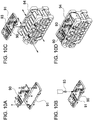
- the circuit substrate is provided with substrate holder 91 for housing the circuit substrate as illustrated in an exploded perspective view of FIG. 10A , liquid resin 93 is filled and cured in a state where circuit substrate 90 is housed in substrate holder 91 as illustrated in FIG. 10B , and then substrate holder 91 is placed on battery holder 94 as illustrated in FIG. 10C , to obtain a battery pack as illustrated in FIG. 10D .
- this configuration has a problem in that a number of parts is increased since the battery holder and the substrate holder are required, and a structure for fixing the substrate holder on the battery holder and a fixing work such as screwing for fixing the substrate holder on the battery holder are required.
- the present invention has been made in view of such a background, and an object of the present invention is to provide a battery pack capable of implementing a configuration for improving heat radiation of a circuit substrate with a potting resin, with a simpler configuration.
- the battery pack includes a plurality of secondary battery cells connected to each other in series and/or in parallel, a battery holder that holds the plurality of secondary battery cells, a circuit substrate connected to the plurality of secondary battery cells, and an outer case that houses the battery holder inside, in which the battery holder is divided into a plurality of divided holders, each of the divided holders forms a fitting structure for fitting the divided holders to each other at an interface for joining the divided holders together, the battery holder forms a substrate holding area that holds the circuit substrate with the circuit substrate surrounded by side walls in a state where the divided holders are coupled to each other by the fitting structure, a joint interface where the divided holders are fitted to each other by the fitting structure of the divided holders is exposed in the substrate holding area, and a surface of the circuit substrate may be covered with a potting resin in the substrate holding area.
- the battery holder may be made of a hard resin.
- the fitting structure may be a spigot structure.
- the fitting structure may include groove portions that are formed at a joint interface of one of the divided holders and separated from each other, and insertion portions that are formed on a joint interface of the other divided holder and press-fitted into the groove portions.
- a pair of sandwiching portions that are separated to form the groove portion may be formed to each have substantially same thickness.
- the substrate holding area is formed in a rectangular shape in a plan view, and the joint interface between the divided holders may be located along a longitudinal direction of the rectangular shape.
- the battery holder may be divided into two parts at substantially a center.
- dividing the battery holder into two halves having substantially the same volume makes it possible to obtain an advantage that the divided holders can be made substantially equal in thickness, and composite molding with one mold is facilitated.
- the battery pack includes a plurality of secondary battery cells connected to each other in series or in parallel, a battery holder that holds the plurality of secondary battery cells, a circuit substrate connected to the plurality of secondary battery cells, and an outer case that houses the battery holder inside.
- the method may include sandwiching the plurality of secondary battery cells to hold the plurality of secondary battery cells in a state where the battery holder is divided into a plurality of divided holders, coupling the divided holders by a fitting structure for fitting the divided holders to each other to form the battery holder, the fitting structure being formed at an interface for joining the divided holders together, and forming a substrate holding area that holds the circuit substrate on an upper surface of the battery holder and in which a joint interface where the divided holders are fitted to each other by the fitting structure of the divided holders is exposed, holding the circuit substrate in the substrate holding area with the circuit substrate surrounded by side walls, covering a surface of the circuit substrate with a potting resin to cure the potting resin in the substrate holding area, and housing the battery holder in the outer case.
- FIGS. 1 to 8 A battery pack according to a first exemplary embodiment of the present invention is illustrated in FIGS. 1 to 8 .
- FIG. 1 is a perspective view illustrating battery pack 100 according to the first exemplary embodiment of the present invention
- FIG. 2 is a sectional view taken along line II-II in FIG. 1
- FIG. 3 is a sectional view taken along line III-III in FIG. 1
- FIG. 4 is an exploded perspective view of battery pack 100 in FIG. 1 with outer case 10 removed
- FIG. 5 is a perspective view of battery holder 20 in FIG. 4
- FIG. 6 is an exploded perspective view illustrating a state where circuit substrate 30 is removed from battery holder 20 in FIG. 5
- FIG. 7 is an exploded perspective view in which battery holder 20 in FIG.
- FIG. 6 is divided into two parts, and FIG. 8 is an exploded perspective view of battery holder 20 in FIG. 7 viewed from a back side.
- Battery pack 100 houses a plurality of secondary battery cells 1 inside, which is connected in series or in parallel to increase a capacity, and enables charging and discharging.
- Battery pack 100 is connected to an external device to be driven, and secondary battery cells 1 are discharged to supply electric power.
- the external device to which battery pack 100 is connected is an assisted bicycle, but the external device to which the battery pack of the present invention is connected is not limited to the assisted bicycle.
- the external device may be other electrical equipment or electronic equipment, for example, an electric tool, agricultural machinery such as a lawn mower, a brush cutter, a sprayer, a small cultivator, a hedge trimmer, and high branch pruning scissors, care and welfare equipment such as a bathing lift, electric assist equipment, auxiliary equipment, and a round-visit car, or a home electric appliance such as a portable light, a lighting device, a cleaner, a camcorder, a portable digital versatile disc (DVD) player, a portable car navigation system, a portable music player, and a laptop computer.
- the battery pack may be directly and removably attached to the external device for use, may be housed or embedded in the external device, or may be connected to the external device via a cable or the like.
- Battery pack 100 is formed in a box shape with its appearance extending in one direction as illustrated in FIGS. 1 to 3 .
- the box-shaped body includes outer case 10.
- Outer case 10 includes connection mechanism 13 and connector 14 for connecting outer case 10 to electrical equipment to be driven (here, the assisted bicycle) to which battery pack 100 supplies electric power.
- a lock mechanism for maintaining battery pack 100 in a state of being attached to the electrical equipment may be provided.
- Outer case 10 is made of a material having excellent insulation and thermal insulation, for example, a resin such as polycarbonate.
- outer case 10 is divided into upper case 11 and lower case 12, and houses battery holder 20 inside.
- Battery holder 20 has a box-like outer shape as illustrated in the perspective view of FIG. 5 .
- Radiation fins 28 are formed on a surface of battery holder 20 to increase a surface area and enhance heat radiation.
- the plurality of radiation fins 28 is projected in front of and behind battery holder 20 so as to be separated from each other.
- circuit substrate 30 is held on an upper surface of battery holder 20.
- battery holder 20 holds the plurality of secondary battery cells 1.
- circuit substrate 30 is held on the upper surface of battery holder 20.
- Battery holder 20 is divided into left and right parts in order to hold secondary battery cells 1.
- Battery holder 20 includes first divided holder 21 and second divided holder 22, and holds secondary battery cells 1 by sandwiching secondary battery cells 1 between first divided holder 21 and second divided holder 22.
- First divided holder 21 and second divided holder 22 hold the plurality of secondary battery cells 1, lead plates 35, and the like.
- secondary battery cells cylindrical secondary battery cells each having a cylindrical exterior can are used.
- 14 secondary battery cells are used, and two sets of battery rows are connected in parallel, in which seven out of the 14 secondary battery cells are connected in series. A number and a connection form of secondary battery cells can be freely changed.
- Each of first divided holder 21 and second divided holder 22 is formed with a plurality of battery holding cylinders 29 for holding secondary battery cells 1, as illustrated in the exploded perspective view of FIG. 7 and the like.
- Each of battery holding cylinders 29 has a depth of about half a length of each of secondary battery cells 1, and secondary battery cells 1 are housed in battery holding cylinders 29 with first divided holder 21 and second divided holder 22 joined together.
- first divided holder 21 and second divided holder 22 expose end surfaces of secondary battery cells 1 from opening windows with secondary battery cells 1 inserted into battery holding cylinders 29, lead plates 35 are held on the opening windows, and lead plates 35 and the end surfaces of secondary battery cells 1 are welded together.
- first divided holder 21 and second divided holder 22 are preferably made of hard resins having excellent insulation and heat resistance.
- first divided holder 21 and second divided holder 22 can be made of polycarbonate or the like. With this configuration, it is possible to insulate and thermally insulate adjacent secondary battery cells 1 from each other.
- Cylindrical secondary battery cells 1 are lithium ion secondary batteries. However, as the cylindrical secondary battery cells, chargeable and dischargeable secondary batteries such as nickel metal hydride batteries or nickel cadmium batteries can be used. Furthermore, secondary battery cells 1 are electrically connected in series or in parallel by lead plates 35. Metal sheets having excellent conductivity are bended to form lead plates 35. Lead plates 35 are welded to electrodes on the end surfaces of secondary battery cells 1. Furthermore, total + and total - of a battery assembly in which secondary battery cells are connected to each other are connected to circuit substrate 30.
- chargeable and dischargeable secondary batteries such as nickel metal hydride batteries or nickel cadmium batteries can be used.
- secondary battery cells 1 are electrically connected in series or in parallel by lead plates 35. Metal sheets having excellent conductivity are bended to form lead plates 35. Lead plates 35 are welded to electrodes on the end surfaces of secondary battery cells 1. Furthermore, total + and total - of a battery assembly in which secondary battery cells are connected to each other are connected to circuit substrate 30.
- Circuit substrate 30 is connected to the plurality of secondary battery cells 1.
- Circuit substrate 30 has a charging and discharging circuit and a protection circuit mounted thereon.
- an intermediate potential lead wire for measuring an intermediate potential may be connected in order to grasp a voltage of each secondary battery cell 1, and a potential of a temperature detector for detecting a temperature of each secondary battery cell 1 may be connected.
- a thermistor or the like is used for the temperature detector.
- battery holder 20 has substrate holding area 23 formed on the upper surface thereof.
- Substrate holding area 23 holds circuit substrate 30 with circuit substrate 30 surrounded by side walls 24.
- Circuit substrate 30 is fixed to substrate holding area 23 by screwing or the like.
- circuit substrate 30 including a mounted semiconductor element and the like is covered with potting resin 40 so as to be embedded.
- the semiconductor element such as a field effect transistor (FET) used as a charging and discharging circuit generates heat, the heat is thermally conducted and radiated by potting resin 40.
- FET field effect transistor
- Substrate holding area 23 is integrally formed with battery holder 20, and thus it is possible to eliminate need to prepare, as a separate member, a substrate holder for holding the substrate, which has been conventionally required.
- Each of the divided holders has a fitting structure for fitting the divided holders to each other at an interface where the divided holders are joined together.
- the divided holders are coupled to each other by this fitting structure to form substrate holding area 23.
- substrate holding area 23 is formed in a rectangular shape in a plan view, and the joint interface between the divided holders is located along a longitudinal direction of the rectangular shape.
- the joint interface where the divided holders are fitted to each other by the fitting structure of the divided holders is exposed. Furthermore, with circuit substrate 30 arranged in substrate holding area 23, a surface of circuit substrate 30 is covered with potting resin 40. With this arrangement, providing the fitting structure at the joint interface between the divided holders so that substrate holding area 23 can be filled with potting resin 40 makes it possible to hold circuit substrate 30 in substrate holding area 23 even if a substrate holder that is a separate member different from battery holder 20 is not separately prepared, unlike a conventional case.
- the fitting structure for fitting first divided holder 21 and second divided holder 22 at the joint interface is preferably a fitting type spigot (inlay) structure as illustrated in FIGS. 3 , 7 , and the like. With this arrangement, it is possible to reduce a gap at the joint interface that joins the divided holders together and to fill substrate holding area 23 with potting resin 40 having a certain degree of viscosity.
- groove portion 25 is formed on the joint interface of first divided holder 21, and insertion portion 26 is formed on the joint interface of second divided holder 22.
- Groove portion 25 is formed between a pair of sandwiching portions that are separated from each other at a constant interval on the joint interface of first divided holder 21.
- Insertion portion 26 is press-fitted into groove portion 25 so that first divided holder 21 and second divided holder 22 are fitted.
- Groove portion 25 and insertion portion 26 are formed in such a size that insertion portion 26 can be press-fitted into groove portion 25 to be fitted therein. Furthermore, as illustrated in the sectional view of FIG.
- the joint interface between first divided holder 21 and second divided holder 22 is formed in a substantially U-shape in cross section, and the fitting structure is also formed in a substantially U-shape along the joint interface.
- the pair of sandwiching portions each have substantially the same thickness.
- battery holder 20 is divided into two parts at substantially a center.
- first divided holder 21 and second divided holder 22 have substantially the same size except for a protruding amount of insertion portion 26, so that molds for first divided holder 21 and second divided holder 22 can be made small as compared with a case where battery holder 20 is integrally formed.
- FIG. 9A cylindrical secondary battery cells 1 are inserted into battery holding cylinders 29 of one of the divided holders (second divided holder 22 in the example of FIG. 9A ) so that secondary battery cells 1 are sandwiched between first divided holder 21 and second divided holder 22.
- the other divided holder first split holder 21 in the example of FIG. 9A
- exposed secondary battery cells 1 are covered with battery holding cylinders 29, and then first divided holder 21 and second divided holder 22 are coupled.
- first divided holder 21 and second divided holder 22 The joint interface between first divided holder 21 and second divided holder 22 is fitted by the fitting structure. That is, insertion portion 26 of second divided holder 22 is press-fitted into groove portion 25 formed at the joint interface of first divided holder 21 to be fitted in groove portion 25. Furthermore, coupling between first divided holder 21 and second divided holder 22 is performed by locking with connecting claws 27 as illustrated in FIG. 9A . However, another double row structure such as screwing may be used. Furthermore, the end surfaces of secondary battery cells 1 are welded to lead plates 35 held by battery holder 20. Thus, as illustrated in FIG. 9B , substrate holding area 23 is formed on the upper surface of battery holder 20.
- circuit substrate 30 is placed and fixed on substrate holding area 23.
- circuit substrate 30 is fixed to substrate holding area 23 by screwing using screw 32, and a lead wire formed on circuit substrate 30 is connected to connection pieces formed on upper ends of lead plates 35 to electrically connect secondary battery cells 1 and circuit substrate 30.
- first divided holder 21 and second divided holder 22 are joined together by the above-described spigot (inlay) structure, it is possible to prevent potting resin 40 from leaking into battery holder 20 from the joint interface.
- Battery holder 20 thus obtained is housed in outer case 10 that is divided into upper case 11 and lower case 12 as illustrated in FIG. 4 , outer case 10 is fixed, and thus battery pack 100 can be obtained.
- the battery pack according to the present invention can be suitably used as a battery pack capable of charging and discharging for a battery-driven device such as a laptop computer, a cellular phone, a portable DVD player, a portable car navigation system, a portable music player, an electric tool, and an assisted bicycle.
- a battery-driven device such as a laptop computer, a cellular phone, a portable DVD player, a portable car navigation system, a portable music player, an electric tool, and an assisted bicycle.
Landscapes
- Chemical & Material Sciences (AREA)
- Chemical Kinetics & Catalysis (AREA)
- Electrochemistry (AREA)
- General Chemical & Material Sciences (AREA)
- Engineering & Computer Science (AREA)
- Manufacturing & Machinery (AREA)
- Materials Engineering (AREA)
- Battery Mounting, Suspending (AREA)
- Secondary Cells (AREA)
Applications Claiming Priority (2)
| Application Number | Priority Date | Filing Date | Title |
|---|---|---|---|
| JP2018029803 | 2018-02-22 | ||
| PCT/JP2019/004526 WO2019163549A1 (fr) | 2018-02-22 | 2019-02-08 | Bloc-batterie et son procédé de production |
Publications (2)
| Publication Number | Publication Date |
|---|---|
| EP3758087A1 true EP3758087A1 (fr) | 2020-12-30 |
| EP3758087A4 EP3758087A4 (fr) | 2021-03-24 |
Family
ID=67687959
Family Applications (1)
| Application Number | Title | Priority Date | Filing Date |
|---|---|---|---|
| EP19757709.1A Pending EP3758087A4 (fr) | 2018-02-22 | 2019-02-08 | Bloc-batterie et son procédé de production |
Country Status (5)
| Country | Link |
|---|---|
| US (1) | US20210057690A1 (fr) |
| EP (1) | EP3758087A4 (fr) |
| JP (1) | JP7325398B2 (fr) |
| CN (1) | CN111699571B (fr) |
| WO (1) | WO2019163549A1 (fr) |
Families Citing this family (4)
| Publication number | Priority date | Publication date | Assignee | Title |
|---|---|---|---|---|
| US11923557B2 (en) | 2018-08-14 | 2024-03-05 | Black & Decker Inc. | Battery pack |
| JP7367182B2 (ja) * | 2020-01-08 | 2023-10-23 | エルジー エナジー ソリューション リミテッド | バッテリーパック、電子デバイス及び自動車 |
| EP3859869A1 (fr) * | 2020-01-28 | 2021-08-04 | Black & Decker Inc. | Bloc-batterie |
| CN212659631U (zh) * | 2020-06-30 | 2021-03-05 | 浙江动一新能源动力科技股份有限公司 | 一种多功能电池包 |
Family Cites Families (13)
| Publication number | Priority date | Publication date | Assignee | Title |
|---|---|---|---|---|
| JP5268393B2 (ja) | 2008-03-07 | 2013-08-21 | 三洋電機株式会社 | バッテリパック |
| JP5496576B2 (ja) | 2009-08-26 | 2014-05-21 | 三洋電機株式会社 | バッテリパック |
| JP2011049012A (ja) | 2009-08-26 | 2011-03-10 | Sanyo Electric Co Ltd | バッテリパック |
| WO2011096159A1 (fr) * | 2010-02-02 | 2011-08-11 | パナソニック株式会社 | Boîtier de batterie et bloc-batterie doté de celui-ci |
| JP2011181415A (ja) * | 2010-03-02 | 2011-09-15 | Sanyo Electric Co Ltd | 安定化回路を備えるバッテリパック |
| CN102195010B (zh) * | 2010-03-10 | 2014-03-12 | 三洋电机株式会社 | 具备导板的电池包 |
| JP5583538B2 (ja) | 2010-10-01 | 2014-09-03 | 三洋電機株式会社 | 電池パック |
| CN104995761A (zh) * | 2013-10-29 | 2015-10-21 | 三洋电机株式会社 | 电源装置 |
| US9893329B2 (en) | 2014-07-04 | 2018-02-13 | Makita Corporation | Electronic power supply device |
| EP3168897B1 (fr) | 2014-07-07 | 2019-06-05 | Sanyo Electric Co., Ltd. | Bloc-batterie et son procédé de fabrication |
| JP2019032924A (ja) * | 2015-12-24 | 2019-02-28 | 三洋電機株式会社 | 電池パックと電池パックの製造方法 |
| CN108370002B (zh) * | 2015-12-28 | 2021-10-01 | 本田技研工业株式会社 | 蓄电装置、框体的密闭结构及框体的制造方法 |
| WO2019021880A1 (fr) | 2017-07-24 | 2019-01-31 | 三洋電機株式会社 | Bloc-batterie et son procédé de fabrication |
-
2019
- 2019-02-08 CN CN201980012644.3A patent/CN111699571B/zh active Active
- 2019-02-08 EP EP19757709.1A patent/EP3758087A4/fr active Pending
- 2019-02-08 JP JP2020501667A patent/JP7325398B2/ja active Active
- 2019-02-08 WO PCT/JP2019/004526 patent/WO2019163549A1/fr unknown
- 2019-02-08 US US16/968,979 patent/US20210057690A1/en active Pending
Also Published As
| Publication number | Publication date |
|---|---|
| JPWO2019163549A1 (ja) | 2021-02-25 |
| WO2019163549A1 (fr) | 2019-08-29 |
| EP3758087A4 (fr) | 2021-03-24 |
| US20210057690A1 (en) | 2021-02-25 |
| JP7325398B2 (ja) | 2023-08-14 |
| CN111699571A (zh) | 2020-09-22 |
| CN111699571B (zh) | 2023-01-17 |
Similar Documents
| Publication | Publication Date | Title |
|---|---|---|
| EP3758087A1 (fr) | Bloc-batterie et son procédé de production | |
| KR101841801B1 (ko) | 엔드 플레이트를 결합시키는 부싱을 포함한 배터리 팩 | |
| KR102036085B1 (ko) | 이차 전지 모듈 | |
| KR102056875B1 (ko) | 배터리 모듈 및 이를 포함하는 배터리 팩 | |
| TWI473324B (zh) | Battery | |
| US20140325831A1 (en) | Battery cover for a high voltage automotive battery | |
| CN210926080U (zh) | 电池单元组件、电池模块、电池组和车辆 | |
| US20140295257A1 (en) | Battery pack and electric device | |
| EP3836247A1 (fr) | Module de batterie, bloc-batterie comprenant un tel module de batterie et véhicule comprenant un tel bloc-batterie | |
| US10608302B2 (en) | Battery pack | |
| TW201126791A (en) | Battery system with a plurality of batteries housed in an external case | |
| US11417923B2 (en) | Battery pack and manufacturing method therefor | |
| KR20190051157A (ko) | 버스바 어셈블리를 포함하는 배터리 모듈 | |
| KR20160030353A (ko) | 전지셀 상호연결 및 전압 센싱 어셈블리, 및 전지모듈 | |
| US20200358055A1 (en) | Battery Pack, Treatment System and Method for the Production of a Battery Pack | |
| JP7295096B2 (ja) | 電池パック | |
| US20200358053A1 (en) | Battery Pack, Treatment System and Method for the Production of a Battery Pack | |
| US20220238966A1 (en) | A battery assmebly | |
| JP6331863B2 (ja) | 蓄電モジュール | |
| WO2019065278A1 (fr) | Bloc batterie | |
| CN109565070A (zh) | 可再充电电池 | |
| JP2021517720A (ja) | 両方向締結構造を有するコネクタを含む電池モジュール | |
| CN110277519A (zh) | 电池组 | |
| EP3792992B1 (fr) | Module de batterie comprenant un boîtier de module | |
| KR20190120154A (ko) | 이차 전지 모듈 |
Legal Events
| Date | Code | Title | Description |
|---|---|---|---|
| STAA | Information on the status of an ep patent application or granted ep patent |
Free format text: STATUS: THE INTERNATIONAL PUBLICATION HAS BEEN MADE |
|
| PUAI | Public reference made under article 153(3) epc to a published international application that has entered the european phase |
Free format text: ORIGINAL CODE: 0009012 |
|
| STAA | Information on the status of an ep patent application or granted ep patent |
Free format text: STATUS: REQUEST FOR EXAMINATION WAS MADE |
|
| 17P | Request for examination filed |
Effective date: 20200818 |
|
| AK | Designated contracting states |
Kind code of ref document: A1 Designated state(s): AL AT BE BG CH CY CZ DE DK EE ES FI FR GB GR HR HU IE IS IT LI LT LU LV MC MK MT NL NO PL PT RO RS SE SI SK SM TR |
|
| AX | Request for extension of the european patent |
Extension state: BA ME |
|
| REG | Reference to a national code |
Ref country code: DE Ref legal event code: R079 Free format text: PREVIOUS MAIN CLASS: H01M0002100000 Ipc: H01M0010613000 |
|
| A4 | Supplementary search report drawn up and despatched |
Effective date: 20210224 |
|
| RIC1 | Information provided on ipc code assigned before grant |
Ipc: H01M 50/287 20210101ALI20210218BHEP Ipc: H01M 10/6555 20140101ALI20210218BHEP Ipc: H01M 10/625 20140101ALI20210218BHEP Ipc: H01M 10/643 20140101ALI20210218BHEP Ipc: H05K 5/00 20060101ALI20210218BHEP Ipc: H01M 10/613 20140101AFI20210218BHEP Ipc: H01M 10/6551 20140101ALI20210218BHEP Ipc: H01M 50/24 20210101ALI20210218BHEP Ipc: H01M 50/213 20210101ALI20210218BHEP Ipc: H01M 50/284 20210101ALI20210218BHEP |
|
| DAV | Request for validation of the european patent (deleted) | ||
| DAX | Request for extension of the european patent (deleted) | ||
| STAA | Information on the status of an ep patent application or granted ep patent |
Free format text: STATUS: EXAMINATION IS IN PROGRESS |
|
| 17Q | First examination report despatched |
Effective date: 20231026 |