EP3757370A2 - Wärmeverwaltungssysteme - Google Patents
Wärmeverwaltungssysteme Download PDFInfo
- Publication number
- EP3757370A2 EP3757370A2 EP20176784.5A EP20176784A EP3757370A2 EP 3757370 A2 EP3757370 A2 EP 3757370A2 EP 20176784 A EP20176784 A EP 20176784A EP 3757370 A2 EP3757370 A2 EP 3757370A2
- Authority
- EP
- European Patent Office
- Prior art keywords
- thermal management
- management system
- sma
- process fluid
- actuator
- Prior art date
- Legal status (The legal status is an assumption and is not a legal conclusion. Google has not performed a legal analysis and makes no representation as to the accuracy of the status listed.)
- Granted
Links
Images







Classifications
-
- F—MECHANICAL ENGINEERING; LIGHTING; HEATING; WEAPONS; BLASTING
- F02—COMBUSTION ENGINES; HOT-GAS OR COMBUSTION-PRODUCT ENGINE PLANTS
- F02C—GAS-TURBINE PLANTS; AIR INTAKES FOR JET-PROPULSION PLANTS; CONTROLLING FUEL SUPPLY IN AIR-BREATHING JET-PROPULSION PLANTS
- F02C7/00—Features, components parts, details or accessories, not provided for in, or of interest apart form groups F02C1/00 - F02C6/00; Air intakes for jet-propulsion plants
- F02C7/12—Cooling of plants
- F02C7/14—Cooling of plants of fluids in the plant, e.g. lubricant or fuel
- F02C7/141—Cooling of plants of fluids in the plant, e.g. lubricant or fuel of working fluid
-
- F—MECHANICAL ENGINEERING; LIGHTING; HEATING; WEAPONS; BLASTING
- F28—HEAT EXCHANGE IN GENERAL
- F28F—DETAILS OF HEAT-EXCHANGE AND HEAT-TRANSFER APPARATUS, OF GENERAL APPLICATION
- F28F27/00—Control arrangements or safety devices specially adapted for heat-exchange or heat-transfer apparatus
- F28F27/02—Control arrangements or safety devices specially adapted for heat-exchange or heat-transfer apparatus for controlling the distribution of heat-exchange media between different channels
-
- F—MECHANICAL ENGINEERING; LIGHTING; HEATING; WEAPONS; BLASTING
- F01—MACHINES OR ENGINES IN GENERAL; ENGINE PLANTS IN GENERAL; STEAM ENGINES
- F01D—NON-POSITIVE DISPLACEMENT MACHINES OR ENGINES, e.g. STEAM TURBINES
- F01D25/00—Component parts, details, or accessories, not provided for in, or of interest apart from, other groups
- F01D25/08—Cooling; Heating; Heat-insulation
- F01D25/12—Cooling
-
- F—MECHANICAL ENGINEERING; LIGHTING; HEATING; WEAPONS; BLASTING
- F01—MACHINES OR ENGINES IN GENERAL; ENGINE PLANTS IN GENERAL; STEAM ENGINES
- F01D—NON-POSITIVE DISPLACEMENT MACHINES OR ENGINES, e.g. STEAM TURBINES
- F01D25/00—Component parts, details, or accessories, not provided for in, or of interest apart from, other groups
- F01D25/08—Cooling; Heating; Heat-insulation
- F01D25/14—Casings modified therefor
-
- F—MECHANICAL ENGINEERING; LIGHTING; HEATING; WEAPONS; BLASTING
- F01—MACHINES OR ENGINES IN GENERAL; ENGINE PLANTS IN GENERAL; STEAM ENGINES
- F01D—NON-POSITIVE DISPLACEMENT MACHINES OR ENGINES, e.g. STEAM TURBINES
- F01D25/00—Component parts, details, or accessories, not provided for in, or of interest apart from, other groups
- F01D25/18—Lubricating arrangements
-
- F—MECHANICAL ENGINEERING; LIGHTING; HEATING; WEAPONS; BLASTING
- F02—COMBUSTION ENGINES; HOT-GAS OR COMBUSTION-PRODUCT ENGINE PLANTS
- F02C—GAS-TURBINE PLANTS; AIR INTAKES FOR JET-PROPULSION PLANTS; CONTROLLING FUEL SUPPLY IN AIR-BREATHING JET-PROPULSION PLANTS
- F02C7/00—Features, components parts, details or accessories, not provided for in, or of interest apart form groups F02C1/00 - F02C6/00; Air intakes for jet-propulsion plants
-
- F—MECHANICAL ENGINEERING; LIGHTING; HEATING; WEAPONS; BLASTING
- F02—COMBUSTION ENGINES; HOT-GAS OR COMBUSTION-PRODUCT ENGINE PLANTS
- F02C—GAS-TURBINE PLANTS; AIR INTAKES FOR JET-PROPULSION PLANTS; CONTROLLING FUEL SUPPLY IN AIR-BREATHING JET-PROPULSION PLANTS
- F02C7/00—Features, components parts, details or accessories, not provided for in, or of interest apart form groups F02C1/00 - F02C6/00; Air intakes for jet-propulsion plants
- F02C7/12—Cooling of plants
- F02C7/14—Cooling of plants of fluids in the plant, e.g. lubricant or fuel
-
- F—MECHANICAL ENGINEERING; LIGHTING; HEATING; WEAPONS; BLASTING
- F02—COMBUSTION ENGINES; HOT-GAS OR COMBUSTION-PRODUCT ENGINE PLANTS
- F02C—GAS-TURBINE PLANTS; AIR INTAKES FOR JET-PROPULSION PLANTS; CONTROLLING FUEL SUPPLY IN AIR-BREATHING JET-PROPULSION PLANTS
- F02C7/00—Features, components parts, details or accessories, not provided for in, or of interest apart form groups F02C1/00 - F02C6/00; Air intakes for jet-propulsion plants
- F02C7/12—Cooling of plants
- F02C7/16—Cooling of plants characterised by cooling medium
- F02C7/18—Cooling of plants characterised by cooling medium the medium being gaseous, e.g. air
-
- F—MECHANICAL ENGINEERING; LIGHTING; HEATING; WEAPONS; BLASTING
- F02—COMBUSTION ENGINES; HOT-GAS OR COMBUSTION-PRODUCT ENGINE PLANTS
- F02K—JET-PROPULSION PLANTS
- F02K1/00—Plants characterised by the form or arrangement of the jet pipe or nozzle; Jet pipes or nozzles peculiar thereto
- F02K1/28—Plants characterised by the form or arrangement of the jet pipe or nozzle; Jet pipes or nozzles peculiar thereto using fluid jets to influence the jet flow
- F02K1/34—Plants characterised by the form or arrangement of the jet pipe or nozzle; Jet pipes or nozzles peculiar thereto using fluid jets to influence the jet flow for attenuating noise
-
- F—MECHANICAL ENGINEERING; LIGHTING; HEATING; WEAPONS; BLASTING
- F02—COMBUSTION ENGINES; HOT-GAS OR COMBUSTION-PRODUCT ENGINE PLANTS
- F02K—JET-PROPULSION PLANTS
- F02K3/00—Plants including a gas turbine driving a compressor or a ducted fan
- F02K3/02—Plants including a gas turbine driving a compressor or a ducted fan in which part of the working fluid by-passes the turbine and combustion chamber
- F02K3/025—Plants including a gas turbine driving a compressor or a ducted fan in which part of the working fluid by-passes the turbine and combustion chamber the by-pass flow being at least partly used to create an independent thrust component
-
- F—MECHANICAL ENGINEERING; LIGHTING; HEATING; WEAPONS; BLASTING
- F03—MACHINES OR ENGINES FOR LIQUIDS; WIND, SPRING, OR WEIGHT MOTORS; PRODUCING MECHANICAL POWER OR A REACTIVE PROPULSIVE THRUST, NOT OTHERWISE PROVIDED FOR
- F03G—SPRING, WEIGHT, INERTIA OR LIKE MOTORS; MECHANICAL-POWER PRODUCING DEVICES OR MECHANISMS, NOT OTHERWISE PROVIDED FOR OR USING ENERGY SOURCES NOT OTHERWISE PROVIDED FOR
- F03G7/00—Mechanical-power-producing mechanisms, not otherwise provided for or using energy sources not otherwise provided for
- F03G7/06—Mechanical-power-producing mechanisms, not otherwise provided for or using energy sources not otherwise provided for using expansion or contraction of bodies due to heating, cooling, moistening, drying or the like
- F03G7/061—Mechanical-power-producing mechanisms, not otherwise provided for or using energy sources not otherwise provided for using expansion or contraction of bodies due to heating, cooling, moistening, drying or the like characterised by the actuating element
- F03G7/0614—Mechanical-power-producing mechanisms, not otherwise provided for or using energy sources not otherwise provided for using expansion or contraction of bodies due to heating, cooling, moistening, drying or the like characterised by the actuating element using shape memory elements
-
- F—MECHANICAL ENGINEERING; LIGHTING; HEATING; WEAPONS; BLASTING
- F03—MACHINES OR ENGINES FOR LIQUIDS; WIND, SPRING, OR WEIGHT MOTORS; PRODUCING MECHANICAL POWER OR A REACTIVE PROPULSIVE THRUST, NOT OTHERWISE PROVIDED FOR
- F03G—SPRING, WEIGHT, INERTIA OR LIKE MOTORS; MECHANICAL-POWER PRODUCING DEVICES OR MECHANISMS, NOT OTHERWISE PROVIDED FOR OR USING ENERGY SOURCES NOT OTHERWISE PROVIDED FOR
- F03G7/00—Mechanical-power-producing mechanisms, not otherwise provided for or using energy sources not otherwise provided for
- F03G7/06—Mechanical-power-producing mechanisms, not otherwise provided for or using energy sources not otherwise provided for using expansion or contraction of bodies due to heating, cooling, moistening, drying or the like
- F03G7/061—Mechanical-power-producing mechanisms, not otherwise provided for or using energy sources not otherwise provided for using expansion or contraction of bodies due to heating, cooling, moistening, drying or the like characterised by the actuating element
- F03G7/0614—Mechanical-power-producing mechanisms, not otherwise provided for or using energy sources not otherwise provided for using expansion or contraction of bodies due to heating, cooling, moistening, drying or the like characterised by the actuating element using shape memory elements
- F03G7/06146—Torque tubes or torsion bars
-
- F—MECHANICAL ENGINEERING; LIGHTING; HEATING; WEAPONS; BLASTING
- F05—INDEXING SCHEMES RELATING TO ENGINES OR PUMPS IN VARIOUS SUBCLASSES OF CLASSES F01-F04
- F05D—INDEXING SCHEME FOR ASPECTS RELATING TO NON-POSITIVE-DISPLACEMENT MACHINES OR ENGINES, GAS-TURBINES OR JET-PROPULSION PLANTS
- F05D2220/00—Application
- F05D2220/30—Application in turbines
- F05D2220/32—Application in turbines in gas turbines
- F05D2220/323—Application in turbines in gas turbines for aircraft propulsion, e.g. jet engines
-
- F—MECHANICAL ENGINEERING; LIGHTING; HEATING; WEAPONS; BLASTING
- F05—INDEXING SCHEMES RELATING TO ENGINES OR PUMPS IN VARIOUS SUBCLASSES OF CLASSES F01-F04
- F05D—INDEXING SCHEME FOR ASPECTS RELATING TO NON-POSITIVE-DISPLACEMENT MACHINES OR ENGINES, GAS-TURBINES OR JET-PROPULSION PLANTS
- F05D2220/00—Application
- F05D2220/30—Application in turbines
- F05D2220/36—Application in turbines specially adapted for the fan of turbofan engines
-
- F—MECHANICAL ENGINEERING; LIGHTING; HEATING; WEAPONS; BLASTING
- F05—INDEXING SCHEMES RELATING TO ENGINES OR PUMPS IN VARIOUS SUBCLASSES OF CLASSES F01-F04
- F05D—INDEXING SCHEME FOR ASPECTS RELATING TO NON-POSITIVE-DISPLACEMENT MACHINES OR ENGINES, GAS-TURBINES OR JET-PROPULSION PLANTS
- F05D2260/00—Function
- F05D2260/20—Heat transfer, e.g. cooling
-
- F—MECHANICAL ENGINEERING; LIGHTING; HEATING; WEAPONS; BLASTING
- F05—INDEXING SCHEMES RELATING TO ENGINES OR PUMPS IN VARIOUS SUBCLASSES OF CLASSES F01-F04
- F05D—INDEXING SCHEME FOR ASPECTS RELATING TO NON-POSITIVE-DISPLACEMENT MACHINES OR ENGINES, GAS-TURBINES OR JET-PROPULSION PLANTS
- F05D2260/00—Function
- F05D2260/20—Heat transfer, e.g. cooling
- F05D2260/213—Heat transfer, e.g. cooling by the provision of a heat exchanger within the cooling circuit
-
- F—MECHANICAL ENGINEERING; LIGHTING; HEATING; WEAPONS; BLASTING
- F05—INDEXING SCHEMES RELATING TO ENGINES OR PUMPS IN VARIOUS SUBCLASSES OF CLASSES F01-F04
- F05D—INDEXING SCHEME FOR ASPECTS RELATING TO NON-POSITIVE-DISPLACEMENT MACHINES OR ENGINES, GAS-TURBINES OR JET-PROPULSION PLANTS
- F05D2270/00—Control
- F05D2270/30—Control parameters, e.g. input parameters
- F05D2270/303—Temperature
-
- F—MECHANICAL ENGINEERING; LIGHTING; HEATING; WEAPONS; BLASTING
- F05—INDEXING SCHEMES RELATING TO ENGINES OR PUMPS IN VARIOUS SUBCLASSES OF CLASSES F01-F04
- F05D—INDEXING SCHEME FOR ASPECTS RELATING TO NON-POSITIVE-DISPLACEMENT MACHINES OR ENGINES, GAS-TURBINES OR JET-PROPULSION PLANTS
- F05D2270/00—Control
- F05D2270/30—Control parameters, e.g. input parameters
- F05D2270/333—Noise or sound levels
-
- F—MECHANICAL ENGINEERING; LIGHTING; HEATING; WEAPONS; BLASTING
- F05—INDEXING SCHEMES RELATING TO ENGINES OR PUMPS IN VARIOUS SUBCLASSES OF CLASSES F01-F04
- F05D—INDEXING SCHEME FOR ASPECTS RELATING TO NON-POSITIVE-DISPLACEMENT MACHINES OR ENGINES, GAS-TURBINES OR JET-PROPULSION PLANTS
- F05D2300/00—Materials; Properties thereof
- F05D2300/50—Intrinsic material properties or characteristics
- F05D2300/505—Shape memory behaviour
-
- F—MECHANICAL ENGINEERING; LIGHTING; HEATING; WEAPONS; BLASTING
- F28—HEAT EXCHANGE IN GENERAL
- F28D—HEAT-EXCHANGE APPARATUS, NOT PROVIDED FOR IN ANOTHER SUBCLASS, IN WHICH THE HEAT-EXCHANGE MEDIA DO NOT COME INTO DIRECT CONTACT
- F28D21/00—Heat-exchange apparatus not covered by any of the groups F28D1/00 - F28D20/00
- F28D2021/0019—Other heat exchangers for particular applications; Heat exchange systems not otherwise provided for
- F28D2021/0021—Other heat exchangers for particular applications; Heat exchange systems not otherwise provided for for aircrafts or cosmonautics
-
- F—MECHANICAL ENGINEERING; LIGHTING; HEATING; WEAPONS; BLASTING
- F28—HEAT EXCHANGE IN GENERAL
- F28D—HEAT-EXCHANGE APPARATUS, NOT PROVIDED FOR IN ANOTHER SUBCLASS, IN WHICH THE HEAT-EXCHANGE MEDIA DO NOT COME INTO DIRECT CONTACT
- F28D21/00—Heat-exchange apparatus not covered by any of the groups F28D1/00 - F28D20/00
- F28D2021/0019—Other heat exchangers for particular applications; Heat exchange systems not otherwise provided for
- F28D2021/0026—Other heat exchangers for particular applications; Heat exchange systems not otherwise provided for for combustion engines, e.g. for gas turbines or for Stirling engines
-
- F—MECHANICAL ENGINEERING; LIGHTING; HEATING; WEAPONS; BLASTING
- F28—HEAT EXCHANGE IN GENERAL
- F28F—DETAILS OF HEAT-EXCHANGE AND HEAT-TRANSFER APPARATUS, OF GENERAL APPLICATION
- F28F2250/00—Arrangements for modifying the flow of the heat exchange media, e.g. flow guiding means; Particular flow patterns
- F28F2250/06—Derivation channels, e.g. bypass
-
- F—MECHANICAL ENGINEERING; LIGHTING; HEATING; WEAPONS; BLASTING
- F28—HEAT EXCHANGE IN GENERAL
- F28F—DETAILS OF HEAT-EXCHANGE AND HEAT-TRANSFER APPARATUS, OF GENERAL APPLICATION
- F28F2255/00—Heat exchanger elements made of materials having special features or resulting from particular manufacturing processes
- F28F2255/04—Heat exchanger elements made of materials having special features or resulting from particular manufacturing processes comprising shape memory alloys or bimetallic elements
-
- F—MECHANICAL ENGINEERING; LIGHTING; HEATING; WEAPONS; BLASTING
- F28—HEAT EXCHANGE IN GENERAL
- F28F—DETAILS OF HEAT-EXCHANGE AND HEAT-TRANSFER APPARATUS, OF GENERAL APPLICATION
- F28F2265/00—Safety or protection arrangements; Arrangements for preventing malfunction
- F28F2265/28—Safety or protection arrangements; Arrangements for preventing malfunction for preventing noise
-
- Y—GENERAL TAGGING OF NEW TECHNOLOGICAL DEVELOPMENTS; GENERAL TAGGING OF CROSS-SECTIONAL TECHNOLOGIES SPANNING OVER SEVERAL SECTIONS OF THE IPC; TECHNICAL SUBJECTS COVERED BY FORMER USPC CROSS-REFERENCE ART COLLECTIONS [XRACs] AND DIGESTS
- Y02—TECHNOLOGIES OR APPLICATIONS FOR MITIGATION OR ADAPTATION AGAINST CLIMATE CHANGE
- Y02T—CLIMATE CHANGE MITIGATION TECHNOLOGIES RELATED TO TRANSPORTATION
- Y02T50/00—Aeronautics or air transport
- Y02T50/60—Efficient propulsion technologies, e.g. for aircraft
Definitions
- the present disclosure relates to thermal management systems.
- Thermal management systems generally may be configured to regulate the temperature of a process fluid, such as an engine oil, via thermal exchange between the process fluid and a thermal management fluid, such as air.
- a thermal management system installed in a turbofan engine of an aircraft may utilize a flow air flow produced by the turbofan engine to decrease a temperature of a hot oil flowing through a conduit.
- incorporation of such thermal management systems into turbofan engines may introduce undesirable aerodynamic drag forces when the conduit is introduced into the air flow, and/or may disrupt acoustic noise attenuation properties of the turbofan engine.
- a thermal management system is configured to regulate a temperature of a process fluid via thermal exchange between the process fluid and a thermal management fluid during operative use of the thermal management system.
- the thermal management system includes a heat exchanger and a housing that selectively and operatively receives the heat exchanger.
- the heat exchanger at least partially defines a heat transfer region configured such that the thermal exchange between the process fluid and the thermal management fluid occurs within the heat transfer region during operative use of the thermal management system.
- the thermal management system further includes a process fluid conduit configured to convey a process fluid flow of the process fluid through the heat transfer region and an actuator assembly configured to selectively position the heat exchanger relative to the housing.
- the process fluid conduit includes a heat transfer portion that extends within the heat transfer region.
- the actuator assembly is configured to selectively assume a position among a plurality of positions that include a stowed position, in which the heat exchanger is substantially received within the housing, and a deployed position, in which the heat exchanger extends from the housing.
- the thermal management system is configured such that, when the actuator assembly is in the deployed position, the heat transfer region extends within a thermal management fluid flow of the thermal management fluid such that the heat transfer portion is in thermal contact with each of the process fluid flow and the thermal management fluid flow and such that the process fluid flow flows in heat exchange relation with the thermal management fluid flow.
- the thermal management system is configured to bring the process fluid into thermal communication with the thermal management fluid within the heat transfer region to change the temperature of the process fluid.
- the thermal management system is configured such that the actuator assembly automatically transitions from the stowed position toward the deployed position when the temperature of the process fluid rises above a predetermined lower threshold temperature and/or when the temperature of the process fluid falls below a predetermined upper threshold temperature.
- At least a portion of the heat exchanger is configured to operate as an acoustic liner that attenuates an acoustic noise propagating through the thermal management fluid flow when the actuator assembly is in one or more of the stowed position, the deployed position, and an intermediate position defined between the stowed position and the deployed position.
- Figs. 1-20 provide illustrative, non-exclusive examples of shape memory alloy (SMA) actuators 210, of thermal management systems 100 including SMA actuators 210, of turbofan engines 20 including thermal management systems 100 and/or SMA actuators 210, of aircraft 10 including turbofan engines 20, and/or of methods 300 of utilizing thermal management systems 100, according to the present disclosure.
- SMA shape memory alloy
- Elements that serve a similar, or at least substantially similar, purpose are labeled with like numbers in each of Figs. 1-20 , and these elements may not be discussed in detail herein with reference to each of Figs. 1-20 .
- all elements may not be labeled in each of Figs. 1-20 , but reference numerals associated therewith may be utilized herein for consistency.
- Figs. 1-2 schematically illustrate examples of thermal management systems 100 according to the present disclosure.
- Thermal management systems 100 according to the present disclosure are configured to regulate a temperature of a process fluid 50 via thermal exchange between process fluid 50 and a thermal management fluid 60 during operative use of thermal management system 100. That is, the present disclosure is directed to systems and structures that are configured to be utilized in conjunction with process fluids 50 and thermal management fluids 60 during operative use thereof. Accordingly, discussions and references herein to process fluid 50 and/or to thermal management fluid 60 are to be understood as describing examples in which thermal management system 100 is in operative use in conjunction with process fluid 50 and thermal management fluid 60.
- thermal management system 100 may be described as being in operative use when utilizing and/or operating relative to process fluid 50 and/or thermal management fluid 60 in any appropriate manner as described herein.
- the systems and apparatuses disclosed herein do not require that process fluid 50 and/or thermal management fluid 60 always be present, and the present disclosure should be understood as describing such systems and apparatuses even in the absence of process fluid 50 and/or thermal management fluid 60.
- thermal management systems 100 generally are configured to regulate the temperature of process fluid 50 by introducing process fluid 50 into heat exchange relation with thermal management fluid 60 depending upon the temperature of process fluid 50.
- thermal management system 100 is configured to automatically introduce process fluid 50 into heat exchange relation with thermal management fluid 60 based upon the temperature of process fluid 50, such as without active control and/or user input. In this manner, such examples of thermal management systems 100 are configured to maintain the temperature of process fluid 50 within a predetermined temperature range by automatically heating or cooling process fluid 50 with thermal management fluid 60 only when the temperature of process fluid 50 departs from the predetermined temperature range.
- thermal management system 100 may introduce process fluid 50 into heat exchange relation with thermal management fluid 60 via manual and/or active control.
- utilizing thermal management systems 100 according to the present disclosure in aeronautical applications additionally may have the benefit of minimizing an aerodynamic drag produced by the thermal management system when process fluid 50 is removed from thermal management fluid 60 and/or of attenuating an acoustic noise associated with thermal management fluid 60.
- thermal management system 100 includes a heat exchanger 110 that at least partially defines a heat transfer region 111 configured such that the thermal exchange between process fluid 50 and thermal management fluid 60 occurs within heat transfer region 111 during operative use of thermal management system 100.
- heat exchanger 110 may include an external surface 120 and an internal surface 130 that extends at least substantially parallel to external surface 120, and heat transfer region 111 may extend between and/or be at least partially defined by external surface 120 and internal surface 130.
- heat exchanger 110 is configured to permit sound waves to propagate through heat transfer region 111 from external surface 120 to internal surface 130 (or vice versa).
- Figs. 1 heat exchanger 110 that at least partially defines a heat transfer region 111 configured such that the thermal exchange between process fluid 50 and thermal management fluid 60 occurs within heat transfer region 111 during operative use of thermal management system 100.
- heat exchanger 110 may include an external surface 120 and an internal surface 130 that extends at least substantially parallel to external surface 120, and heat transfer region 111 may extend between and/or be at least partially defined by external surface 120 and internal surface 130
- each of external surface 120 and internal surface 130 may be at least substantially planar. However, this is not required, and it is additionally within the scope of the present disclosure that external surface 120 and internal surface 130 each may have any appropriate shape or configuration, such as a curved and/or arcuate shape.
- Thermal management system 100 additionally includes a housing 140 that selectively and operatively receives heat exchanger 110, as well as an actuator assembly 200 configured to selectively position heat exchanger 110 relative to housing 140.
- actuator assembly 200 is configured to selectively assume a position among a plurality of positions that include a stowed position (schematically illustrated in Fig. 1 ), in which heat exchanger 110 is at least substantially received within housing 140, and a deployed position (schematically illustrated in Fig. 2 ), in which heat exchanger 110 extends from housing 140.
- Actuator assembly 200 also may be described as being in an intermediate position when actuator assembly 200 is in any of the plurality of positions defined between and excluding the stowed position and the deployed position. In this manner, heat exchanger 110 may be only partially received within housing 140 when actuator assembly 200 is in an intermediate position. Stated differently, heat exchanger 110 may extend only partially from housing 140 when actuator assembly 200 is in an intermediate position.
- thermal management system 100 and/or heat exchanger 110 also may be described as being in the stowed position when actuator assembly 200 is in the stowed position. Similarly, thermal management system 100 and/or heat exchanger 110 also may be described as being in the deployed position when actuator assembly 200 is in the deployed position.
- each of heat exchanger 110 and/or housing 140 may include one or more sliding guides 118 configured to at least partially maintain an alignment of heat exchanger 110 relative to housing 140 as heat exchanger 110 translates relative to housing 140, such as while actuator assembly 200 transitions between the stowed position and the deployed position.
- each sliding guide 118 may include and/or be a low-friction surface.
- sliding guide 118 of heat exchanger 110 may include an interfacing surface that engages sliding guide 118 of housing 140, and/or vice-versa. That is, while Figs. 1-2 schematically illustrate heat exchanger 110 (and sliding guide 118 thereof) as being spaced apart from housing 140 for clarity, heat exchanger 110 may be in sliding contact with housing 140 via sliding guide(s) 118.
- thermal management system 100 further includes a process fluid conduit 160 configured to convey a process fluid flow 52 of process fluid 50 through heat transfer region 111.
- process fluid conduit 160 includes a heat transfer portion 166 that extends within heat transfer region 111.
- Thermal management system 100 is configured such that, when actuator assembly 200 is in the deployed position (as schematically illustrated in Fig. 2 ), heat transfer region 111 extends within a thermal management fluid flow 62 of thermal management fluid 60 such that heat transfer portion 166 of process fluid conduit 160 is in thermal contact with each of process fluid flow 52 and thermal management fluid flow 62 and such that process fluid flow 52 flows in heat exchange relation with thermal management fluid flow 62.
- heat exchanger 110 when heat exchanger 110 extends from housing 140 and into thermal management fluid flow 62, heat transfer region 111 and heat transfer portion 166 are exposed to thermal management fluid flow 62 such that thermal communication may take place between thermal management fluid 60 and process fluid 50.
- heat exchanger 110 when actuator assembly 200 is in the stowed position, heat exchanger 110 is substantially removed from thermal management fluid flow 62, such that process fluid 50 is substantially thermally isolated from thermal management fluid 60.
- thermal management system 100 and/or any component thereof may be described as being “in operative use” and/or as being “operatively utilized” when process fluid flow 52 exists within process fluid conduit and/or when thermal management fluid flow 62 exists within and/or adjacent to heat exchanger 110, regardless of whether actuator assembly 200 is in the stowed position, the deployed position, or any of the plurality of intermediate positions.
- process fluid flow 52 may refer to a flow characteristic of process fluid 50 and/or may refer to process fluid 50 itself.
- a reference to a flow of process fluid 50 also may be referred to as process fluid flow 52 (and/or a characteristic thereof).
- a characteristic of process fluid flow 52 also may be understood as describing process fluid 50.
- process fluid flow 52 may be described as including and/or consisting of process fluid 50.
- thermal management fluid flow 62 may refer to a flow characteristic of thermal management fluid 60 and/or may refer to thermal management fluid 60 itself.
- thermal management flow 62 a reference to a flow of thermal management fluid 60 also may be referred to as thermal management flow 62 (and/or a characteristic thereof).
- a characteristic of thermal management fluid flow 62 also may be understood as describing thermal management fluid 60.
- thermal management fluid flow 62 flowing through the region a description of thermal management fluid 60 flowing through a region equivalently may be described as thermal management fluid flow 62 flowing through the region.
- thermal management system 100 is configured such that actuator assembly 200 automatically transitions between the stowed position and the deployed position, such as based upon a temperature of process fluid 50 within process fluid conduit 160.
- actuator assembly 200 may include an SMA actuator 210 that automatically transitions heat transfer region 111 into and out of thermal management fluid flow 62 based upon the temperature of process fluid 50 that is in thermal contact with SMA actuator 210.
- Thermal management system 100 additionally or alternatively may be configured to exhibit acoustic damping properties (e.g., acoustic noise attenuation properties) when actuator assembly 200 is in one or both of the stowed position and the deployed position and/or when actuator assembly 200 is in the intermediate position.
- acoustic damping properties e.g., acoustic noise attenuation properties
- thermal management system 100 may be configured such that an acoustic noise propagating through thermal management fluid flow 62 is mitigated and/or attenuated by the presence of thermal management system 100 regardless of the position of actuator assembly 200.
- the acoustic noise propagating through thermal management fluid flow 62 may be mitigated and/or attenuated by the presence of thermal management system 100 when actuator assembly 200 is in the stowed position, in the deployed position, and/or in one or more of the intermediate positions defined between the stowed position and the deployed position.
- at least a portion of heat exchanger 110 (such as external surface 120 and/or internal surface 130) may be configured to operate as an acoustic liner 34 that attenuates acoustic noise propagating through thermal management fluid flow 62 when actuator assembly 200 is in one or more of the stowed position, the deployed position, and the intermediate position.
- external surface 120 may define a plurality of external perforations 122 configured to permit sound waves to traverse external surface 120
- internal surface 130 may define a plurality of internal perforations 132 configured to permit sound waves to traverse internal surface 130.
- heat exchanger 110 may be configured such that sound waves (such as may be propagating through and/or otherwise associated with thermal management fluid flow 62) may enter and/or traverse heat transfer region 111 when actuator assembly 200 is in the stowed position, and such that the sound waves may enter housing 140 when actuator assembly 200 is in the deployed position.
- external surface 120 and/or internal surface 130 may restrict fluid from traversing the surface other than via external perforations 122 and/or internal perforations 132.
- housing 140 may define a housing volume 142 such that heat exchanger 110 is at least substantially received within housing volume 142 when actuator assembly 200 is in the stowed position, and external surface 120 may substantially restrict thermal management fluid flow 62 from entering housing volume 142 other than through external perforations 122 when actuator assembly 200 is in the stowed position.
- internal surface 130 may substantially restrict thermal management fluid flow 62 from entering housing volume 142 other than through internal perforations 132 when actuator assembly 200 is in the deployed position.
- thermal management system 100 may include one or more acoustic cavities 150 configured to attenuate acoustic noise, such as may be propagating through and/or otherwise associated with thermal management fluid flow 62.
- Each acoustic cavity 150 generally is configured to permit sound waves to enter the acoustic cavity 150, such as via external perforations 122 and/or internal perforations 132, and to attenuate an acoustic noise associated with the sound waves by establishing a resonance of the sound waves.
- one or more acoustic cavities 150 each may operate as a Helmholtz resonator.
- each acoustic cavity 150 generally is substantially defined by external surface 120, internal surface 130, and/or housing 140.
- external surface 120, internal surface 130, and/or housing 140 collectively may define one or more acoustic cavities 150. More specifically, and with reference to Fig. 1 , when actuator assembly 200 is in the stowed position, sound waves may enter each acoustic cavity 150 that is defined by external surface 120, internal surface 130, and housing 140 from thermal management fluid flow 62 at least substantially and/or only via external perforations 122.
- actuator assembly 200 when actuator assembly 200 is in the stowed position, sound waves may enter each acoustic cavity 150 that is defined by internal surface 130 and housing 140 from thermal management fluid flow 62 at least substantially and/or only via external perforations 122 and internal perforations 132 (and the acoustic cavities 150 defined therebetween).
- internal surface 130 and housing 140 When actuator assembly 200 is in the deployed position (as schematically illustrated in Fig. 2 ) and/or when actuator assembly 200 is in the intermediate position, internal surface 130 and housing 140 collectively may define one or more acoustic cavities 150, such that sound waves may enter each acoustic cavity 150 at least substantially and/or only via internal perforations 132.
- housing 140 additionally may include one or more bulkheads 144 statically extending within housing volume 142 of housing 140 along a direction at least substantially perpendicular to thermal management fluid flow 62.
- each bulkhead 144 at least partially defines one or more acoustic cavities 150.
- each bulkhead 144 generally is configured to permit actuator assembly 200 to transition between the stowed position and the deployed position without heat exchanger 110 interfering with bulkhead 144.
- heat exchanger 110 at least partially receives each bulkhead 144, such as within a slot 116 defined by heat exchanger 110.
- Heat exchanger 110, external surface 120, internal surface 130, housing 140, and/or bulkhead(s) 144 may have any appropriate respective shapes, sizes, and/or configurations, such as for enhancing acoustic attenuation of sound waves propagating through thermal management fluid flow 62.
- the plurality of external perforations 122 and/or the plurality of internal perforations 132 may be configured to yield a porosity of the respective surfaces of heat exchanger 110 that is selected to optimize propagation of sound waves into acoustic cavities 150 and/or to attenuate sound waves.
- the plurality of external perforations 122 collectively may yield a porosity of external surface 120 that is at least 1%, at least 3%, at least 5%, at least 10%, at least 15%, at least 20%, at least 30%, at least 40%, at least 50%, at most 55%, at most 45%, at most 35%, at most 25%, at most 17%, at most 12%, at most 7%, or at most 2%.
- the plurality of internal perforations 132 collectively may yield a porosity of internal surface 132 that is at least 1%, at least 3%, at least 5%, at least 10%, at least 15%, at least 20%, at least 30%, at least 40%, at least 50%, at most 55%, at most 45%, at most 35%, at most 25%, at most 17%, at most 12%, at most 7%, and/or at most 2%.
- porosity generally refers to a ratio of a combined surface area of a collection of perforations to a total surface area of a region across which the perforations are distributed.
- each acoustic cavity 150 may have any appropriate dimensions, such as may be selected to promote a resonance of sound waves of a predetermined frequency.
- each acoustic cavity 150 may have a cavity length 152, as measured along a direction parallel to thermal management fluid flow 62, that is at least 1 centimeter (cm), at least 3 cm, at least 5 cm, at least 10 cm, at least 15 cm, at most 20 cm, at most 17 cm, at most 12 cm, at most 7 cm, and/or at most 2 cm.
- cm centimeter
- each acoustic cavity 150 may have a cavity depth 154, as measured along a direction perpendicular to external surface 120, that is at least 1 cm, at least 3 cm, at least 5 cm, at least 10 cm, at least 15 cm, at most 20 cm, at most 17 cm, at most 12 cm, at most 7 cm, and/or at most 2 cm.
- heat exchanger 110 While the examples illustrated and described herein generally pertain to examples in which heat exchanger 110 includes a single external surface 120 and a single internal surface 130, it is additionally within the scope of the present disclosure that heat exchanger 110 may include a plurality of spaced-apart internal surfaces 130, such as may include corresponding pluralities of internal perforations 132. In such examples, each internal surface 130 may include any appropriate aspects, features, and/or configurations of internal surface 130 as discussed herein.
- heat exchanger 110 additionally may include one or more features configured to enhance an aerodynamic property of heat exchanger 110.
- external surface 120 additionally may include a shaped leading edge 124 that is configured to mitigate a drag force imparted on heat exchanger 110 by thermal management fluid flow 62 when actuator assembly 200 is in the deployed position and/or in the stowed position.
- shaped leading edge 124 may be curved and/or airfoil-shaped.
- Process fluid conduit 160 may include any appropriate portions and/or components for conveying process fluid 50 as described herein.
- process fluid conduit 160 may include a supply conduit 162 and a return conduit 164 such that process fluid 50 is supplied to heat transfer portion 166 via supply conduit 162 and returns from heat transfer portion 166 via return conduit 164.
- each of supply conduit 162 and return conduit 164 is operatively coupled to heat exchanger 110 and is fluidly coupled to heat transfer portion 166 such that process fluid flow 52 flows through supply conduit 162 prior to flowing through heat transfer portion 166 and flows through return conduit 164 subsequent to flowing through heat transfer portion 166.
- Supply conduit 162 and/or return conduit 164 may have any appropriate form and/or structure, such as to facilitate actuator assembly 200 transitioning between the stowed position and the deployed position.
- supply conduit 162 and/or return conduit 164 may include and/or be a flexible tube configured to passively deform as actuator assembly 200 transitions between the stowed position and the deployed position.
- supply conduit 162 and/or return conduit 164 may include a portion of actuator assembly 200, for example such that supply conduit 162 and/or return conduit 164 actively deforms to transition actuator assembly 200 between the stowed position and the deployed position.
- supply conduit 162 and/or return conduit 164 may include and/or be SMA actuator 210.
- Process fluid 50 and/or thermal management fluid 60 may include and/or be any appropriate fluids such that thermal management fluid 60 may be utilized to regulate a temperature of process fluid 50.
- process fluid 50 may include and/or be a liquid, water, a coolant, propylene glycol, ethylene glycol, a lubricant, an oil, a gas, and/or air.
- thermal management fluid 60 may include and/or be a gas, air, a liquid, water, and/or an organic compound.
- process fluid 50 may be an engine oil
- thermal management fluid 60 may be air, such that a flow of the air relative to the engine may be utilized to cool the engine oil.
- process fluid 50 may be a coolant oil that is utilized by an electrical generator
- thermal management fluid 60 may be air, such that a flow of the air relative to the electrical generator may be utilized to cool the coolant oil, thereby facilitating a cooling of the electrical generator.
- thermal management system 100 generally is configured to bring process fluid 50 into thermal communication with thermal management fluid 60 within heat transfer region 111 to change the temperature of process fluid 50 during operative use of thermal management system 100, such as when actuator assembly 200 is in the deployed position and/or when actuator assembly 200 is in any of the intermediate positions.
- thermal management system 100 may be configured to decrease the temperature of process fluid 50.
- thermal management system 100 may be configured such that actuator assembly 200 automatically transitions from the stowed position toward the deployed position when the temperature of process fluid 50 rises above a predetermined lower threshold temperature, and/or such that actuator assembly 200 automatically transitions from the deployed position toward the stowed position when the temperature of process fluid 50 falls below a predetermined upper threshold temperature.
- thermal management system 100 may be configured to increase the temperature of process fluid 50.
- thermal management system 100 may be configured such that actuator assembly 200 automatically transitions from the stowed position toward the deployed position when the temperature of process fluid 50 falls below a predetermined upper threshold temperature, and/or such that actuator assembly 200 automatically transitions from the deployed position toward the stowed position when the temperature of process fluid 50 rises above a predetermined lower threshold temperature.
- thermal management system 100 also may be configured such that actuator assembly 200 assumes and/or remains in the stowed position when the temperature of process fluid 50 is within a nominal temperature range.
- thermal management system 100 also may be configured such that actuator assembly 200 assumes and/or remains in an intermediate position defined between the stowed position and the deployed position when the temperature of process fluid 50 is between the predetermined lower threshold temperature and the predetermined upper threshold temperature.
- Thermal management system 100, heat exchanger 110, process fluid conduit 160, and/or heat transfer portion 166 may be configured to facilitate and/or enhance thermal communication between process fluid 50 and thermal management fluid 60 in any appropriate manner.
- heat transfer portion 166 may include a plurality of heat transfer passages 168 extending within heat transfer region 111 such that process fluid 50 flows through each of the plurality of heat transfer passages 168 during operative use of thermal management system 100.
- process fluid conduit 160 additionally may include a supply manifold 172 and/or a return manifold 174 configured such that process fluid flow 52 flows sequentially from supply manifold 172 through one or more heat transfer passages 168 and to return manifold 174.
- supply manifold 172 may be configured to supply process fluid flow 52 to each of the plurality of heat transfer passages 168, and/or return manifold 174 may be configured to collect process fluid flow 52 from each of the plurality of heat transfer passages 168.
- supply manifold 172 and/or return manifold 174 may be statically coupled to heat exchanger 110, for example such that supply manifold 172 and/or return manifold 174 moves with heat exchanger 110 as actuator assembly 200 transitions between the stowed configuration and the deployed configuration.
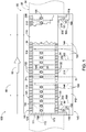
- FIG. 3 schematically illustrates selected components of examples of heat exchangers 100 according to the present disclosure and represents a cross-sectional view taken along the line 3-3 in Fig. 1 .
- Fig. 4 represents a cross-sectional view taken along the line 4-4 in Fig. 2 .
- Fig. 3 may be described as illustrating thermal management system 100 with heat exchanger 110 in the stowed position, while Fig. 4 may be described as illustrating thermal management system 100 with heat exchanger 110 in the deployed position.
- Figs. 3 schematically illustrates selected components of examples of heat exchangers 100 according to the present disclosure and represents a cross-sectional view taken along the line 3-3 in Fig. 1 .
- Fig. 4 represents a cross-sectional view taken along the line 4-4 in Fig. 2 .
- Fig. 3 may be described as illustrating thermal management system 100 with heat exchanger 110 in the stowed position
- Fig. 4 may be described as illustrating thermal management system 100 with heat exchanger 110 in the deployed position.
- FIG. 3-4 additionally may be described as illustrating an example in which each of supply conduit 162 and return conduit 164 includes a flexible tube.
- Figs. 3-4 illustrate an example of thermal management system 100 in which process fluid flow 52 flows sequentially from supply conduit 162 to supply manifold 172, through one or more heat transfer passages 168 (one of which is visible in Figs. 3-4 ), to return manifold 174, and through return conduit 164.
- Heat transfer passages 168 may extend through and/or occupy heat transfer region 111 in any appropriate manner, such as may be configured to facilitate thermal communication between process fluid flow 52 within heat transfer passages 168 and thermal management fluid flow 62 exterior of heat transfer passages 168. Additionally, heat transfer passages 168 may be arranged, spaced, and/or otherwise configured to permit sound waves to propagate between external surface 120 and internal surface 130, such as from external surface 120 to internal surface 130 and/or from internal surface 130 to external surface 120. Stated differently, and as schematically illustrated in Figs. 1-2 , the plurality of heat transfer passages 168 may define a plurality of gaps therebetween such that sound waves (such as may be propagating through and/or otherwise associated with thermal management fluid 60) may traverse heat transfer portion 166.
- heat transfer region 111 may be described as encompassing a heat transfer region area, as measured within a plane that extends parallel to thermal management fluid flow 62, and the plurality of heat transfer passages 168 collectively may occupy a passage cross-sectional area, as measured in the plane that extends parallel to thermal management fluid flow 62, that is at least 10%, at least 15%, at least 20%, at least 30%, at least 40%, at least 50%, at most 90%, at most 75%, at most 45%, at most 35%, at most 25%, at most 17%, and/or at most 12% of the heat transfer region area.
- heat exchanger 110 further may include one or more heat spreaders 112 in thermal communication and/or direct contact with heat transfer portion 166.
- heat spreader 112 is configured to enhance the thermal communication between thermal management fluid 60 that flows through heat transfer region 111 and process fluid 50 that flows within heat transfer portion 166.
- heat spreader 112 may be at least substantially positioned within heat transfer region 111, and/or may be at least substantially positioned between external surface 120 and internal surface 130.
- Heat spreader 112 may include and/or be any suitable heat spreader such as is known in the field of thermal management, examples of which include a heat sink, a fin, and/or a plate.
- heat spreader 112 When present, heat spreader 112 generally is configured to permit a flow of fluid through heat transfer region 111. Stated differently, heat spreader 112 may be shaped, positioned, and/or otherwise configured to permit thermal management fluid 60 (and/or any other fluid) to flow through heat transfer region 111 without being substantially restricted by heat spreader 112. For example, and as schematically illustrated in Figs. 1-2 , heat spreader 112 may define a plurality of heat spreader passages 114 configured to permit fluid and/or sound waves to traverse heat spreader 112, such as from external surface 120 to internal surface 130 (or vice versa). Additionally or alternatively, and as schematically illustrated in Figs.
- heat spreader 112 may include and/or substantially consist of a plurality of spaced-apart plates such that thermal management fluid 60 may flow through heat transfer region 111 along the direction of thermal management fluid flow 62 during operative use of thermal management system 100.
- the voids defined between adjacent plates may be referred to as heat spreader passages 114.
- heat spreader passages 114 may be configured to permit thermal management fluid flow 62 to flow through heat transfer region 111, such as in the manner schematically illustrated in Fig. 2 .
- Such a configuration also may permit sound waves to propagate through heat transfer region 111, such as from external surface 120 to internal surface 130.
- process fluid flow 52 generally flows through heat transfer portion 166 and/or through one or more heat transfer passages 168 when actuator assembly 200 is in the deployed position so as to establish thermal communication between process fluid flow 52 and thermal management fluid flow 62. It is additionally within the scope of the present disclosure that process fluid flow 52 flows through heat transfer portion 166 and/or through one or more heat transfer passages 168 when actuator assembly 200 is in any of the plurality of positions defined between and including the stowed position and the deployed position. Stated differently, thermal management systems 100 according to the present disclosure may be configured such that process fluid flow 52 flows through process fluid conduit 160 (and/or through any portion thereof) regardless of the configuration of actuator assembly 200.
- Figs. 1-4 generally correspond to examples in which heat exchanger 110 translates relative to housing 140 as actuator assembly 200 transitions between the stowed position and the deployed position. However, this is not required, and it is additionally within the scope of the present disclosure that actuator assembly 200 may transition heat exchanger 110 into and out of thermal management fluid flow 62 via pivotal and/or rotational motion.
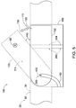
- Fig. 5 schematically illustrates such an example of thermal management system 100. Specifically, and as schematically illustrated in Fig. 5 , heat exchanger 110 may be configured to pivot relative to housing 140 about a pivot axis 102 as actuator assembly 200 transitions between the stowed position (illustrated in solid lines) and the deployed position (illustrated in dashed lines).
- Such a configuration may enable supply conduit 162 or return conduit 164 to remain at least substantially stationary as actuator assembly 200 transitions between the stowed position and the deployed position. Stated differently, such a configuration may enable supply conduit 162 or return conduit 164 to remain at a substantially static location relative to housing 140 as actuator assembly 200 transitions between the stowed position and the deployed position. Such a configuration may serve to mitigate a mechanical wear endured by process fluid conduit 160 as heat exchanger 110 is deployed from and returned to housing 140.
- Fig. 5 schematically illustrates an example in which pivot axis 102 is at least substantially parallel to thermal management fluid flow 62. However, this is not required, and it is additionally within the scope of the present disclosure that pivot axis 102 may be at least partially, and/or at least substantially, perpendicular to thermal management fluid flow 62.
- thermal management system 100 may be configured such that actuator assembly 200 automatically transitions between the stowed position and the deployed position based upon the temperature of process fluid 50, such as may be achieved by SMA actuator 210.
- SMA actuator 210 generally is configured to assume a conformation among a plurality of conformations defined between and including a first conformation and a second conformation, such that the position of actuator assembly 200 is at least partially based on the conformation of SMA actuator 210.
- SMA actuator 210 is configured to be in thermal contact with process fluid 50 such that the conformation of SMA actuator 210 is based, at least in part, on the temperature of process fluid 50 that is in thermal contact with SMA actuator 210.
- actuator assembly 200 may be configured to automatically assume a position among the plurality of positions based upon the conformation of SMA actuator 210, which in turn is based upon the temperature of process fluid 50. More specifically, actuator assembly 200 may be in the stowed position when SMA actuator 210 is in the first conformation, and actuator assembly 200 may be in the deployed position when SMA actuator 210 is in the second conformation. Similarly, actuator assembly 200 may be in the intermediate position when SMA actuator 210 is in an intermediate conformation defined between the first conformation and the second conformation.
- SMA actuator 210 may have any appropriate form, construction, and/or functionality, examples of which are provided in U.S. Patent Application Serial No. 15/901,779 , the complete disclosure of which is hereby incorporated by reference. As schematically illustrated in Figs. 1-2 , SMA actuator 210 may be at least substantially formed of an SMA material 211, such as may be specifically trained and/or configured to transition between the first conformation and the second conformation to transition actuator assembly 200 between the stowed position and the deployed position.
- SMA material 211 may include and/or be any appropriate material, examples of which include a binary alloy; a nickel-titanium alloy; a binary nickel-titanium alloy; a ternary alloy; a ternary alloy that includes nickel and titanium; a ternary nickel-titanium-palladium alloy; a ternary manganese-nickel-cobalt alloy; a quaternary alloy; a quaternary alloy that includes nickel and titanium; and/or an alloy that includes at least one of nickel, titanium, palladium, manganese, hafnium, copper, iron, silver, cobalt, chromium, and vanadium.
- SMA material 211 may have and/or be characterized by a crystalline structure thereof.
- SMA material 211 may be configured to transition from a martensite state to an austenite state responsive to the temperature of SMA material 211 increasing, and may be configured to transition from the austenite state to the martensite state responsive to the temperature of SMA material 211 decreasing.
- SMA actuator 210 may be in the first conformation when SMA material 211 is in the martensite state, and SMA actuator 210 may be in the second conformation when SMA material 211 in the austenite state.
- SMA actuator 210 may be in the first conformation when SMA material 211 is in the austenite state, and SMA actuator 210 may be in the second conformation when SMA material 211 in the martensite state.
- a temperature-dependent transition between the austenite state and the martensite state of SMA material 211 may have any appropriate form.
- Fig. 6 illustrates a hysteresis curve that represents a relationship between the state of SMA material 211 and the temperature of SMA material 211.
- SMA material 211 may be configured to begin a transition from the martensite state to the austenite state when SMA material 211 reaches an initial heating temperature (labeled T H,I in Fig. 6 ) from below (i.e., from a temperature that is lower than the initial heating temperature).
- SMA material 211 may be configured to transition from the martensite state to the austenite state as the temperature of SMA material 211 is increased.
- SMA material 211 may be configured to complete the transition from the martensite state to the austenite state upon reaching a final heating temperature (labeled T H,F in Fig. 6 ) that is greater than the initial heating temperature.
- SMA material 211 may be configured to begin a transition from the austenite state to the martensite state upon reaching an initial cooling temperature (labeled T C,I in Fig. 6 ) from above (i.e., from a temperature that is greater than the initial cooling temperature).
- SMA material 211 may be configured to transition from the austenite state to the martensite state as the temperature of SMA material 211 is decreased.
- SMA material 211 may be configured to complete the transition from the austenite state to the martensite state upon reaching a final cooling temperature (labeled T C,F in Fig. 6 ) that is less than the initial cooling temperature.
- the initial heating temperature may be greater than the final cooling temperature, and/or the final heating temperature may be greater than the initial cooling temperature.
- a crystalline structure of SMA material 211 may depend upon both the temperature of SMA material 211 as well as a history of the temperature of SMA material 211 when the temperature is between the final cooling temperature and the final heating temperature.
- SMA material 211 may be configured to remain in the austenite state when the temperature of SMA material 211 is greater than the final heating temperature, and/or may be configured to remain in the martensite state when the temperature of SMA material 211 is less than the final cooling temperature.
- SMA material 211 may be configured and/or calibrated such that the final cooling temperature is higher than a minimum operational temperature of SMA material 211 and/or of process fluid 50, and/or such that the final heating temperature is lower than a maximum operational temperature of SMA material 211 and/or of process fluid 50.
- SMA material 211 may be selected, tailored, trained, and/or otherwise configured such that the minimum and/or maximum operational temperatures of SMA material 211 correspond to the minimum and/or maximum expected and/or desired temperatures of process fluid 50.
- Such a configuration may facilitate a precise and/or reliable determination of a position of actuator assembly 200 as SMA material 211 is transitioned between the minimum operational temperature and the maximum operational temperature.
- SMA actuator 210 may be incorporated into thermal management system 100 in any appropriate manner to transition actuator assembly 200 between the stowed position and the deployed position as described herein.
- process fluid conduit 160 may include SMA actuator 210 such that process fluid 50 flows through at least a portion of SMA actuator 210.
- Figs. 7-10 illustrate more specific examples of SMA actuators 210, as discussed in more detail herein.
- process fluid conduit 160 may be configured such that process fluid flow 52 flows through SMA actuator 210 from an upstream end 216 of SMA actuator 210 to a downstream end 218 of SMA actuator 210.
- process fluid 50 may flow through SMA actuator 210 in any appropriate portion of process fluid conduit 160.
- process fluid conduit 160 may be configured to such that process fluid 50 flows through heat transfer portion 166 subsequent to flowing through SMA actuator 210, prior to flowing through SMA actuator 210, and/or at least partially concurrent with flowing through SMA actuator 210.
- thermal management system 100 may be configured to change the temperature of process fluid 50 (via thermal communication with thermal management fluid flow 62) subsequent to process fluid 50 flowing through SMA actuator 210, prior to process fluid 50 flowing through SMA actuator 210, and/or at least partially concurrent with process fluid 50 flowing through SMA actuator 210.
- SMA actuator 210 may assume any appropriate form and/or configuration for transitioning actuator assembly 200 between the stowed position and the deployed position.
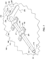
- Fig. 7 illustrates an example in which SMA actuator 210 includes an SMA torque tube 230 configured to produce a torque as SMA actuator 210 transitions between the first conformation and the second conformation.
- SMA torque tube 230 may be tubular and/or cylindrical.
- SMA torque tube 230 may be characterized by a longitudinal axis 232 such that SMA torque tube 230 is configured to twist about longitudinal axis 232 as SMA actuator 210 transitions between the first conformation and the second conformation.
- SMA torque tube 230 twisting about longitudinal axis 232 operates to transition actuator assembly 200 between the stowed position and the deployed position.
- SMA torque tube 230 may be fixedly and/or statically coupled to at least a portion of a remainder of thermal management system 100, such as heat exchanger 110 and/or housing 140. More specifically, and as shown in Fig. 7 , SMA torque tube 230 may be described as including a static portion 234 that is fixedly coupled to heat exchanger 110 or to housing 140 and an active portion 236 configured to twist relative to static portion 234. As further illustrated in Fig. 7 , actuator assembly 200 additionally may include an actuation element 220 that is fixedly coupled to active portion 236 and that extends away from SMA torque tube 230.
- actuation element 220 may be configured to rotate relative to longitudinal axis 232 in a first direction 222 as SMA actuator 210 transitions from the first conformation toward the second conformation, and may be configured to rotate relative to longitudinal axis 232 in a second direction 224 that is opposite first direction 222 as SMA actuator 210 transitions from the second conformation toward the first conformation.
- actuator assembly 200 may include a linkage mechanism 202 that is configured to convert twisting motion of active portion 236 into a force (such as a linear force and/or a torque) to transition actuator assembly 200 between the stowed position and the deployed position and/or to translate and/or rotate heat exchanger 110 relative to housing 140. At least a portion of linkage mechanism 202 may be fixedly coupled to active portion 236.
- linkage mechanism 202 may include actuation element 220 fixedly coupled to active portion 236.
- linkage mechanism 202 may include one or more actuator arms 204, such as may be fixedly coupled to active portion 236.
- actuation element 220 may include and/or be actuator arm 204, and/or linkage mechanism 202 may be described as including actuation element 220.
- fixedly coupled refers to a configuration in which the first component is statically coupled to the second component in such a manner that the two components move, translate, pivot, and/or rotate in unison.
- actuation element 220 may be described as being fixedly coupled to active portion 236 when actuation element 220 is operatively coupled to active portion 236 such that actuation element 220 rotates about longitudinal axis 232 as active portion 236 twists about longitudinal axis 232. It is additionally within the present disclosure that one or more components of linkage mechanism 202 may be rotatably coupled and/or hingedly coupled to a portion of SMA torque tube 230, such as active portion 236. In such examples, a twisting of active portion 236 may operate to translate and/or rotate heat exchanger 110 relative to housing 140 via a rotational and/or hinged coupling between SMA torque tube 230 and linkage mechanism 202.
- actuator arm 204 generally refers to a component of linkage mechanism 202 such that at least a portion of actuator arm 204 is configured to rotate with respect to one of housing 140 and heat exchanger 110 and such that at least a portion of actuator arm 204 is configured to translate with respect to the other of housing 140 and heat exchanger 110.
- actuator arm 204 may be described as enabling the conversion of a rotation (such as the twisting of SMA torque tube 230) to a translation (such as a translation of heat exchanger 110 relative to housing 140 as actuator assembly 220 transitions between the stowed position and the deployed position).
- static portion 234 of SMA torque tube 230 may be fixedly coupled to housing 140, and at least a portion of linkage mechanism 202 may be fixedly coupled to heat exchanger 110.
- static portion 234 may be fixedly coupled to heat exchanger 110, and at least a portion of linkage mechanism 202 may be fixedly coupled to housing 140.
- SMA actuator 210 may be configured to transition between the first conformation and the second conformation at least substantially via a translation of and/or within SMA actuator 210.
- SMA actuator 210 may be described as including and/or being an SMA lifting tube 250 that is configured to be in thermal communication with process fluid 50. More specifically, SMA lifting tube 250 may be a hollow SMA lifting tube 250 configured to permit process fluid flow 52 of process fluid 50 to flow therethrough and in thermal contact with SMA lifting tube 250.
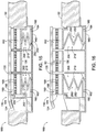
- Figs. 8-10 illustrate examples of SMA actuators 210 that include SMA lifting tubes 250.
- SMA lifting tube 250 generally includes and extends between a first end 212 and a second end 214 such that second end 214 is configured to translate relative to first end 212 (or, equivalently, vice versa). More specifically, and as illustrated in Figs. 8-10 , SMA lifting tube 250 is configured such that second end 214 translates relative to first end 212 at least partially along a lateral direction 226 that is at least substantially perpendicular to at least a portion of SMA lifting tube 250 between first end 212 and second end 214 as SMA actuator 210 transitions between the first conformation and the second conformation.
- SMA lifting tube 250 may be configured to perform work on a load that is operatively coupled to SMA lifting tube 250 as SMA actuator 210 transitions between the first conformation and the second conformation.
- SMA actuator 210 may be configured to translate the first component and the second component relative to one another at least partially along lateral direction 226 as SMA actuator 210 transitions between the first conformation and the second conformation.
- SMA actuator 210 may be configured to exert a force to push the first component and the second component away from one another, and/or may be configured to exert a force to pull the first component and the second component toward one another. Additionally or alternatively, SMA actuator 210 and/or SMA lifting tube 250 may be configured to restrict second end 214 from translating relative to first end 212 along lateral direction 226 when SMA material 211 is in a given (i.e., substantially constant) state defined between and including the martensite state and the austenite state.
- SMA actuator 210 and/or SMA lifting tube 250 may be substantially rigid at least when actuator assembly 200 is not actively transitioning between the stowed position and the deployed position and/or when SMA actuator 210 is not actively transitioning between the first conformation and the second conformation.
- SMA material 211 being maintained in a given state may correspond to SMA material 211 and/or SMA lifting tube 250 being maintained at a substantially constant temperature, such as may be the case when process fluid 50 flowing through SMA lifting tube 250 is at a temperature that is substantially constant (in time and/or across a length of SMA lifting tube).
- process fluid 50 flowing through SMA lifting tube 250 is at a temperature that is substantially constant (in time and/or across a length of SMA lifting tube).
- SMA lifting tube 250 may be characterized by a separation distance 260 between first end 212 and second end 214 as measured along a direction parallel to lateral direction 226, and SMA actuator 210 may be configured to maintain first end 212 and second end 214 at a substantially constant separation distance 260 when process fluid 50 flowing in thermal communication with SMA lifting tube 250 is at a substantially constant temperature such that SMA material 211 is at a substantially constant temperature.
- SMA lifting tube 250 may be sufficiently rigid to maintain actuator assembly 200 in a given position defined between and including the stowed position and the deployed position.
- SMA lifting tube 250 may be sufficiently rigid to resist actuator assembly 200 from transitioning between the stowed position and the deployed position other than via a temperature-induced change in the state of SMA material 211.
- SMA lifting tube 250 is configured such that first end 212 and second end 214 are at least substantially maintained in a fixed rotational orientation relative to one another as SMA actuator 210 transitions between the first conformation and the second conformation, and/or as actuator assembly 200 that includes SMA lifting tube 250 transitions between the stowed position and the deployed position.
- Such functionality is schematically illustrated in Figs. 8-10 via elongate indicators affixed to (e.g., painted onto) each of first end 212 and second end 214 in each Figure. In this manner, Figs.
- FIG. 8-9 illustrate second end 214 as being is in the same rotational orientation (both in an absolute sense and relative to first end 212) whether SMA actuator 210 is in the first conformation ( Fig. 8 ) or in the second conformation ( Fig. 9 ).
- Fig. 10 illustrates second end 214 as being in the same rotational orientation (both in an absolute sense and relative to first end 212) whether SMA actuator 210 is in the first conformation (solid lines) or in the second conformation (dashed lines).
- Such a configuration may be beneficial in an example in which SMA lifting tube 250 forms a portion of a conduit (such as process fluid conduit 160) since this configuration permits non-rotating couplings to be made to each of first end 212 and second end 214 while exerting no or minimal torque on such couplings as SMA actuator 210 transitions between the first conformation and the second conformation.
- SMA lifting tube 250 generally may be configured to permit a fluid (such as process fluid 50) to flow through SMA lifting tube 250.
- first end 212 may include and/or be upstream end 216 of SMA lifting tube 250 and second end 214 may include and/or be downstream end 218 of lifting tube 250, such that process fluid 50 flows through SMA lifting tube 250 from upstream end 216 to downstream end 218.
- lateral direction 226 may be described as being at least substantially perpendicular to a direction of process fluid flow 52 of process fluid 50 within at least a portion of SMA lifting tube 250, such as a direction of process fluid flow 52 adjacent to and downstream of upstream end 216 and/or adjacent to and upstream of downstream end 218.
- Figs. 8-10 illustrate process fluid 50 as flowing from first end 212 to second end 214, this is not required, and it is additionally within the scope of the present disclosure that SMA lifting tube 250 is configured such that process fluid 50 flows from second end 214 to first end 212.
- second end 214 may include and/or be upstream end 216 and first end 212 may include and/or be downstream end 218.
- SMA lifting tube 250 may have any appropriate shape and/or configuration for producing a translation between first end 212 and second end 214.
- SMA lifting tube 250 may extend along a path that is helical, cylindrical, S-shaped, U-shaped, and/or coil-shaped.
- SMA lifting tube 250 may include and/or be an SMA coil 252 that extends at least substantially within a coil plane 254 when SMA actuator 210 is in the first conformation or in the second conformation.
- lateral direction 226 may be at least substantially perpendicular to coil plane 254, such that SMA coil 252 deforms along lateral direction 226 to transition SMA actuator 210 between the first conformation and the second conformation.
- Fig. 8 may be described as illustrating SMA actuator 210 in the first conformation
- Fig. 9 may be described as illustrating SMA actuator 210 in the second conformation.
- Fig. 10 illustrates an additional example of SMA lifting tube 250.
- SMA lifting tube 250 is substantially S-shaped and is configured such that first end 212 travels relative to second end 214 at least partially along a transverse direction 228 that is perpendicular to lateral direction 226 as SMA actuator 210 transitions between the first conformation (solid lines) and the second conformation (dashed lines).
- second end 214 is configured to move relative to first end 212 along an arcuate path that may be characterized as including both a translation partially along lateral direction 226 and a translation partially along transverse direction 228.
- thermal management systems 100 of Figs. 11-16 illustrate examples of thermal management systems 100 with actuator assemblies 200 and/or SMA actuators 210 in various configurations.
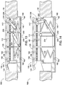
- thermal management systems 100 of Figs. 11-16 include heat exchangers 110 that are substantially identical but that are transitioned between the stowed position ( Figs. 11 , 13 , and 15 ) and the deployed position ( Figs. 12 , 14 , and 16 ) by distinct mechanisms.
- Figs. 11-12 illustrate an example in which actuator assembly 200 includes SMA torque tube 230 that is at least partially statically coupled to housing 140 and actuation element 220 extending away from SMA torque tube 230.
- an end of actuation element 220 that is distal SMA torque tube 230 (and/or a pin rotatably coupled to such an end) is slidably received within a guide slot such that rotation of actuation element 220 corresponds with the end of actuation element 220 sliding within the guide slot.
- twisting of SMA torque tube 230 results in rotation of actuation element 220, which in turn serves to transition actuator assembly 200 between the stowed position ( Fig. 11 ) and the deployed position ( Fig.
- actuation element 220 may be described as representing actuator arm 204 of linkage mechanism 202, as described above.
- each of supply conduit 162 and return conduit 164 takes the form of a flexible tube.
- Figs. 13-14 illustrate another example in which actuator assembly 200 includes SMA torque tube 230 and actuation element 220 extending away from SMA torque tube 230.
- SMA torque tube 230 is operatively coupled to heat exchanger 110 and at least partially received within heat transfer region 111 of heat exchanger 110 such that process fluid 50 that flows through SMA torque tube 230 is in thermal communication with thermal management fluid 60 when actuator assembly 200 is in the deployed position and during operative use of thermal management system 100.
- actuator assembly 200 further includes an instance of heat spreader 112 in the form of one or more discs affixed to SMA torque tube 230.
- Figs. 13-14 additionally illustrate an example in which actuator assembly 200 includes linkage mechanism 202.
- linkage mechanism 202 serves to operatively couple SMA torque tube 230 to housing 140.
- linkage mechanism 202 includes actuation element 220 extending from SMA torque tube 230, as well as actuator arm 204 that is rotatably coupled to interior surface 130 of heat exchanger 110 and slidingly coupled to housing 140 via a guide slot.
- Actuation element 220 is operatively coupled to actuator arm 204 via an intermediate element.
- a twisting of SMA torque tube 230 yields a rotation of actuation element 220, urging actuator arm 204 to slide relative to housing 140, which in turn produces a translation of heat exchanger 110 relative to housing 140.
- Figs. 15-16 illustrate an example in which actuator assembly 200 includes one or more SMA lifting tubes 250.
- return conduit 164 includes SMA lifting tube 250 such that SMA actuator 210 transitioning between the first conformation and the second conformation serves to translate heat exchanger 110 relative to housing 140 via a linear force.
- supply conduit 162 may include and/or be a flexible tube.
- supply conduit 162 may include SMA lifting tube 250 and return conduit 164 may include and/or be a flexible tube.
- supply conduit 162 and return conduit 164 each may include SMA lifting tube 250.
- SMA lifting tube 250 of supply conduit 162 and SMA lifting tube 250 of return conduit 164 may be described as operating as antagonistic SMA actuators 210.
- Fig. 17 is a less schematic illustration of an example of thermal management system 100 installed relative to structural surface 32.
- Fig. 17 illustrates thermal management system 100 with actuator assembly 200 in the deployed position.
- actuator assembly 200 includes SMA actuator 210 in the form of SMA torque tube 230 with a pair of static portions 234 fixedly coupled to housing 140 and active portion 236 positioned between static portions 234.
- Actuator assembly 200 further includes linkage mechanism 202 that includes actuator arm 204 in the form of actuation element 220 fixedly coupled to SMA torque tube 230 and slidingly coupled to heat exchanger 110 via a guide slot (only a portion of which is visible in Fig. 17 ). Additional elements shown and labeled in Fig. 17 are to be understood with reference to corresponding portions of the above discussion.
- Fig. 18 is an illustration of an aircraft 10 that may include and/or utilize thermal management systems 100, SMA actuators 210, and/or methods 300, according to the present disclosure.
- aircraft 10 may include one or more wings 12, a horizontal stabilizer 14, a vertical stabilizer 16, an airframe 18, and/or one or more turbofan engines 20.
- Examples of aircraft 10 include an airplane, a commercial aircraft, a passenger aircraft, and/or a military aircraft.
- Aircraft 10 may include and/or utilize thermal management systems 100 and/or SMA actuators 210 according to the present disclosure.
- thermal management system 100 and/or SMA actuators 210 may be incorporated into and/or utilized by turbofan engine(s) 20 and/or by any other appropriate component of aircraft 10, such as liquid-cooled electronics systems and/or an auxiliary power unit (APU).
- turbofan engine(s) 20 and/or by any other appropriate component of aircraft 10, such as liquid-cooled electronics systems and/or an auxiliary power unit (APU).
- APU auxiliary power unit
- Fig. 19 is a schematic cross-sectional illustration of turbofan engine 20, such as may be utilized by aircraft 10 and/or such as may include and/or utilize thermal management system 100 and/or SMA actuators 210 according to the present disclosure.
- turbofan engine 20 may include a fan 22 configured to generate an air flow 24 to produce a thrust, an engine core 26 configured to generate a torque to power fan 22, and an engine core cowl 36 that at least substantially covers engine core 26.
- Turbofan engine 20 further may include a nacelle 30 that at least substantially encloses fan 22 and engine core 26, as well as a bypass duct 28 defined between engine core cowl 36 and nacelle 30 such that air flow 24 flows within bypass duct 28.
- a nacelle 30 that at least substantially encloses fan 22 and engine core 26, as well as a bypass duct 28 defined between engine core cowl 36 and nacelle 30 such that air flow 24 flows within bypass duct 28.
- turbofan engine 20 additionally may include thermal management system 100, such as may include and/or utilize SMA actuator 210, as described herein.
- air flow 24 may include and/or be thermal management fluid flow 62.
- process fluid 50 may include and/or be any appropriate process fluid utilized by turbofan engine 20, examples of which include an engine oil that is utilized by engine core 26 and a lubricating and/or cooling oil that is utilized by an engine accessory such as a generator.
- thermal management system 100 may be supported by and/or a component of any appropriate portion of turbofan engine 20.
- thermal management system 100 may be operatively coupled to and/or incorporated into engine core cowl 36 and/or nacelle 30.
- thermal management system 100 may be installed adjacent to structural surface 32 of engine core cowl 36 and/or of nacelle 30, for example such that external surface 120 of heat exchanger 110 is at least substantially continuous and/or coplanar with structural surface 32 when actuator assembly 200 is in the stowed position, such as is illustrated in Figs. 1 , 5 , 11 , 13 , and 15 .
- structural surface 32 may include and/or be acoustic liner 34 configured to attenuate an acoustic noise propagating through air flow 24 through bypass duct 28.
- thermal management system 100 in conjunction with turbofan engine 20 may be beneficial since heat exchanger 110 extends into thermal management fluid flow 62 only when actuator assembly 200 is in the deployed position, thereby minimizing the aerodynamic drag produced by heat exchanger 110.
- utilizing heat exchanger 110 adjacent to acoustic liner 34 of turbofan engine 20 may enable thermal management system 100 to exhibit acoustic noise attenuation properties when actuator assembly 200 is in either of the stowed position or the deployed position and/or in any of the plurality of intermediate positions defined between the stowed position and the deployed position.
- Fig. 20 is a flowchart depicting methods 300, according to the present disclosure, of utilizing a thermal management system (such as thermal management system 100) to passively regulate a temperature of a process fluid (such as process fluid 50) with a thermal management fluid (such as thermal management fluid 60).
- a method 300 includes conveying, at 310, the process fluid through a process fluid conduit (such as process fluid conduit 160) of the thermal management system such that the process fluid is in thermal contact with an SMA actuator (such as SMA actuator 210), and conveying, at 320, the process fluid through the process fluid conduit such that the process fluid flows through a heat transfer region (such as heat transfer region 111) of the heat exchanger.
- a process fluid conduit such as process fluid conduit 160
- SMA actuator such as SMA actuator 210
- Method 300 additionally includes transitioning, at 330, the SMA actuator to assume a conformation among a plurality of conformations defined between and including a first conformation (such as the first conformation of SMA actuator 210) and a second conformation (such as the second conformation of SMA actuator 210) based upon a temperature of the process fluid that is in contact with the SMA actuator, and transitioning, at 340, the heat exchanger to assume a position among a plurality of positions defined between and including a stowed position (such as the stowed position of heat exchanger 110) and a deployed position (such as the deployed position of heat exchanger 110) based upon the conformation of the SMA actuator.
- a first conformation such as the first conformation of SMA actuator 210
- a second conformation such as the second conformation of SMA actuator 2
- the heat transfer region when the heat exchanger is in the deployed position, the heat transfer region extends within a thermal management fluid flow (such as thermal management fluid flow 62) of the thermal management fluid such that the process fluid is in heat exchange relation with the thermal management fluid, thereby enabling the thermal management fluid to regulate the temperature of the process fluid.
- a thermal management fluid flow such as thermal management fluid flow 62
- the conveying the process fluid in thermal contact with the SMA actuator at 310 and the conveying the process fluid through the heat transfer region at 320 may be performed in any appropriate order and/or manner.
- the conveying at 310 may be performed prior to the conveying at 320, may be performed subsequent to the conveying at 320, and/or may be performed at least partially concurrent with the conveying at 320.
- the transitioning the SMA actuator among the plurality of conformations at 330 may include distorting and/or manipulating the SMA actuator and/or a portion thereof in any appropriate manner.
- the SMA actuator may include and/or be an SMA torque tube (such as SMA torque tube 230), and the transitioning at 330 may include twisting, at 332, the SMA torque tube about a longitudinal axis (such as longitudinal axis 232).
- the twisting at 332 additionally may include rotating an actuation element (such as actuation element 220) that is coupled to the SMA torque tube about the longitudinal axis.
- the twisting at 332 may include rotating the actuation element about the longitudinal axis in a first direction (such as first direction 222) responsive to the SMA actuator transitioning from the first conformation toward the second conformation, and may include rotating the actuation element about the longitudinal axis in a second direction (such as second direction 224) that is opposite the first direction responsive to the SMA actuator transitioning from the second conformation toward the first conformation.
- the SMA actuator may include and/or be an SMA lifting tube (such as SMA lifting tube 250), and the transitioning at 330 may include translating, at 334, a first end (such as first end 212) of the SMA lifting tube relative to a second end (such as second end 214) of the SMA lifting tube at least partially along a lateral direction (such as lateral direction 226) that is at least substantially perpendicular to at least a portion of the SMA lifting tube between the first end and the second end.
- a first direction that is at least substantially parallel to a second direction includes a first direction that is within an angular deviation of 22.5° relative to the second direction and also includes a first direction that is identical to the second direction.
- the terms “selective” and “selectively” thus may characterize an activity that is a direct or indirect result of user manipulation of an aspect of, or one or more components of, the apparatus, or may characterize a process that occurs automatically, such as via the mechanisms disclosed herein.
- the terms “adapted” and “configured” mean that the element, component, or other subject matter is designed and/or intended to perform a given function. Thus, the use of the terms “adapted” and “configured” should not be construed to mean that a given element, component, or other subject matter is simply “capable of” performing a given function but that the element, component, and/or other subject matter is specifically selected, created, implemented, utilized, programmed, and/or designed for the purpose of performing the function. It is also within the scope of the present disclosure that elements, components, and/or other recited subject matter that is recited as being adapted to perform a particular function may additionally or alternatively be described as being configured to perform that function, and vice versa. Similarly, subject matter that is recited as being configured to perform a particular function may additionally or alternatively be described as being operative to perform that function.
- the term "and/or" placed between a first entity and a second entity means one of (1) the first entity, (2) the second entity, and (3) the first entity and the second entity.
- Multiple entries listed with “and/or” should be construed in the same manner, i.e., "one or more" of the entities so conjoined.
- Other entities optionally may be present other than the entities specifically identified by the "and/or” clause, whether related or unrelated to those entities specifically identified.
- a reference to "A and/or B,” when used in conjunction with open-ended language such as “comprising,” may refer, in one example, to A only (optionally including entities other than B); in another example, to B only (optionally including entities other than A); in yet another example, to both A and B (optionally including other entities).
- These entities may refer to elements, actions, structures, steps, operations, values, and the like.
- the phrase "at least one,” in reference to a list of one or more entities should be understood to mean at least one entity selected from any one or more of the entities in the list of entities, but not necessarily including at least one of each and every entity specifically listed within the list of entities and not excluding any combinations of entities in the list of entities.
- This definition also allows that entities may optionally be present other than the entities specifically identified within the list of entities to which the phrase "at least one" refers, whether related or unrelated to those entities specifically identified.
- At least one of A and B may refer, in one embodiment, to at least one, optionally including more than one, A, with no B present (and optionally including entities other than B); in another embodiment, to at least one, optionally including more than one, B, with no A present (and optionally including entities other than A); in yet another embodiment, to at least one, optionally including more than one, A, and at least one, optionally including more than one, B (and optionally including other entities).
- each of the expressions “at least one of A, B, and C,” “at least one of A, B, or C,” “one or more of A, B, and C,” “one or more of A, B, or C,” and “A, B, and/or C” may mean A alone, B alone, C alone, A and B together, A and C together, B and C together, A, B, and C together, and optionally any of the above in combination with at least one other entity.
- the phrase, "for example,” the phrase, “as an example,” and/or simply the term “example,” when used with reference to one or more components, features, details, structures, embodiments, and/or methods according to the present disclosure, are intended to convey that the described component, feature, detail, structure, embodiment, and/or method is an illustrative, non-exclusive example of components, features, details, structures, embodiments, and/or methods according to the present disclosure.
Landscapes
- Engineering & Computer Science (AREA)
- Chemical & Material Sciences (AREA)
- Combustion & Propulsion (AREA)
- Mechanical Engineering (AREA)
- General Engineering & Computer Science (AREA)
- Physics & Mathematics (AREA)
- Thermal Sciences (AREA)
- Heat-Exchange Devices With Radiators And Conduit Assemblies (AREA)
Applications Claiming Priority (1)
| Application Number | Priority Date | Filing Date | Title |
|---|---|---|---|
| US16/457,789 US11168584B2 (en) | 2019-06-28 | 2019-06-28 | Thermal management system using shape memory alloy actuator |
Publications (3)
| Publication Number | Publication Date |
|---|---|
| EP3757370A2 true EP3757370A2 (de) | 2020-12-30 |
| EP3757370A3 EP3757370A3 (de) | 2021-02-24 |
| EP3757370B1 EP3757370B1 (de) | 2023-07-05 |
Family
ID=70861303
Family Applications (1)
| Application Number | Title | Priority Date | Filing Date |
|---|---|---|---|
| EP20176784.5A Active EP3757370B1 (de) | 2019-06-28 | 2020-05-27 | Wärmeverwaltungssysteme |
Country Status (3)
| Country | Link |
|---|---|
| US (1) | US11168584B2 (de) |
| EP (1) | EP3757370B1 (de) |
| CN (1) | CN112145297B (de) |
Families Citing this family (5)
| Publication number | Priority date | Publication date | Assignee | Title |
|---|---|---|---|---|
| US11525438B2 (en) * | 2019-06-28 | 2022-12-13 | The Boeing Company | Shape memory alloy actuators and thermal management systems including the same |
| US11459909B2 (en) * | 2020-09-15 | 2022-10-04 | Pratt & Whitney Canada Corp. | Rotating heat exchanger |
| US11591965B2 (en) * | 2021-03-29 | 2023-02-28 | General Electric Company | Thermal management system for transferring heat between fluids |
| US12259196B2 (en) * | 2022-06-16 | 2025-03-25 | The Boeing Company | Sound-attenuating heat exchangers and methods of exchanging heat and attenuating sound within sound-attenuating heat exchangers |
| US12253027B2 (en) | 2022-11-14 | 2025-03-18 | Pratt & Whitney Canada Corp. | Lubricant reservoir with integrated heat exchanger |
Family Cites Families (96)
| Publication number | Priority date | Publication date | Assignee | Title |
|---|---|---|---|---|
| NL23603C (de) | 1927-12-29 | |||
| GB588520A (en) | 1945-02-26 | 1947-05-27 | Ag Fuer Technische Studien | Improvements in tubular gas heaters |
| US2886121A (en) | 1956-10-25 | 1959-05-12 | John T Welbourn | Air-cooled silencer |
| US2988302A (en) | 1959-01-14 | 1961-06-13 | Gen Sound Control Inc | Silencing means for aircraft |
| NL249238A (de) | 1959-03-09 | |||
| US3229762A (en) | 1963-05-25 | 1966-01-18 | Schmidt Sche Heissdampf | Welded heat exchanger |
| US4060127A (en) | 1975-04-15 | 1977-11-29 | Nikolai Ivanovich Savin | Shell-and-tube heat exchanger |
| US4151710A (en) | 1977-03-11 | 1979-05-01 | United Technologies Corporation | Lubrication cooling system for aircraft engine accessory |
| US4203392A (en) | 1978-03-03 | 1980-05-20 | Mclane Jack S | Heat exchanger |
| GB2038410B (en) | 1978-12-27 | 1982-11-17 | Rolls Royce | Acoustic lining utilising resonance |
| US4266602A (en) | 1980-02-21 | 1981-05-12 | Westinghouse Electric Corp. | Heat exchanger for cooling electrical power apparatus |
| GB2106190A (en) | 1981-07-31 | 1983-04-07 | Leuven Res & Dev Vzw | Thermally responsive actuators utilising shape memory, and exercising devices utilising the same |
| FR2549585A1 (en) | 1983-07-21 | 1985-01-25 | Axergie Sa | Evaporator for an installation with a closed thermodynamic loop for the flow of a working fluid, and installation incorporating this evaporator |
| JPS6026181A (ja) | 1983-07-22 | 1985-02-09 | Mitsubishi Electric Corp | 形状記憶合金バネ |
| US4700541A (en) | 1986-10-16 | 1987-10-20 | American Telephone And Telegraph Company, At&T Bell Laboratories | Shape memory alloy actuator |
| US4790624A (en) | 1986-10-31 | 1988-12-13 | Identechs Corporation | Method and apparatus for spatially orienting movable members using shape memory effect alloy actuator |
| US5127228A (en) | 1991-02-07 | 1992-07-07 | Swenson Steven R | Shape memory bi-directional rotary actuator |
| US5150864A (en) | 1991-09-20 | 1992-09-29 | Georgia Tech Research Corporation | Variable camber control of airfoil |
| JPH06249129A (ja) | 1993-02-22 | 1994-09-06 | Jamco Corp | モータ |
| FR2705445B1 (fr) | 1993-05-18 | 1995-07-07 | Vicarb Sa | Echangeur de chaleur à plaques. |
| JPH07167036A (ja) | 1993-12-15 | 1995-07-04 | Tokin Corp | アクチュエータ |
| JPH10176651A (ja) | 1996-12-18 | 1998-06-30 | Tokin Corp | 駆動素子 |
| US6499952B1 (en) | 1997-02-28 | 2002-12-31 | The Boeing Company | Shape memory alloy device and control method |
| US6065934A (en) | 1997-02-28 | 2000-05-23 | The Boeing Company | Shape memory rotary actuator |
| FR2761116B1 (fr) | 1997-03-18 | 1999-06-04 | Matra Marconi Space France | Actionneur rotatif a barreau en alliage a memoire de forme |
| US6358276B1 (en) | 1998-09-30 | 2002-03-19 | Impra, Inc. | Fluid containing endoluminal stent |
| KR20020021809A (ko) | 1999-08-12 | 2002-03-22 | 추후기재 | 형상 기억 합금 액추에이터 및 제어 방법 |
| WO2001016484A2 (en) | 1999-09-02 | 2001-03-08 | Teledyne Technologies, Inc. | A magnetically-assisted shape memory alloy actuator |
| KR20010087231A (ko) | 2000-03-03 | 2001-09-15 | 레비스 스테픈 이 | 형상 기억 합금 번들 및 액추에이터 |
| US6832477B2 (en) | 2000-05-08 | 2004-12-21 | Mark A Gummin | Shape memory alloy actuator |
| WO2002079786A2 (en) | 2001-03-30 | 2002-10-10 | Biostratum Ab | Method for identifying drugs for the treatment of type ii diabetes |
| JP4418817B2 (ja) | 2003-02-27 | 2010-02-24 | ユニヴァーシティ オブ ワシントン | 強磁性形状記憶合金複合材料および前記材料を組み込んだアクチュエータの設計 |
| FR2862353B1 (fr) | 2003-11-17 | 2007-08-17 | Commissariat Energie Atomique | Actionneur multi-stable a base d'alliage a memoire de forme, et interface tactile le mettant en oeuvre |
| JP4465684B2 (ja) | 2004-01-20 | 2010-05-19 | 独立行政法人科学技術振興機構 | 形状記憶合金を用いた駆動機構及びこの駆動機構を備える装置 |
| US7299630B2 (en) | 2004-03-12 | 2007-11-27 | Gm Global Technology Operations, Inc. | Positioning and locking mechanisms and articles that employ the same |
| US7311175B2 (en) | 2005-08-10 | 2007-12-25 | United Technologies Corporation | Acoustic liner with bypass cooling |
| US7850623B2 (en) | 2005-10-27 | 2010-12-14 | Boston Scientific Scimed, Inc. | Elongate medical device with continuous reinforcement member |
| US7464548B2 (en) | 2005-11-30 | 2008-12-16 | The Boeing Company | Shape memory alloy linear actuator |
| US7878459B2 (en) | 2007-06-29 | 2011-02-01 | The Boeing Company | Aircraft systems with shape memory alloy (SMA) actuators, and associated methods |
| JP4832373B2 (ja) | 2007-07-10 | 2011-12-07 | オリンパス株式会社 | 形状記憶合金アクチュエータ |
| EP2192289B1 (de) | 2007-09-13 | 2012-04-25 | Alphatech CO., LTD. | Ansaugschalldämpfer für eine gasturbine |
| US7771392B2 (en) | 2007-11-29 | 2010-08-10 | Roche Diagnostics Operations, Inc. | Lead screw delivery device using reusable shape memory actuator drive |
| TW200928098A (en) | 2007-12-31 | 2009-07-01 | Chicony Electronics Co Ltd | Actuation device with shape memory alloy |
| US8104278B2 (en) | 2008-03-31 | 2012-01-31 | GM Global Technology Operations LLC | Energy harvesting, storing, and conversion utilizing shape memory activation |
| WO2010023876A1 (ja) | 2008-08-26 | 2010-03-04 | パナソニック株式会社 | 導電性高分子を用いた流体搬送装置 |
| US8678299B2 (en) | 2008-10-29 | 2014-03-25 | Korea Institute Of Machinery & Materials | Hollow actuator-driven droplet dispensing apparatus |
| US8769947B2 (en) | 2009-11-20 | 2014-07-08 | GM Global Technology Operations LLC | Exhaust system |
| GB2476855B (en) | 2009-11-27 | 2012-05-02 | Rolls Royce Plc | Acoustic liner and heat exchanger for gas turbine inlet duct |
| GB201001410D0 (en) | 2010-01-29 | 2010-03-17 | Rolls Royce Plc | Oil cooler |
| WO2011115883A2 (en) | 2010-03-15 | 2011-09-22 | The Trustees Of Dartmouth College | Geometry of heat exchanger with high efficiency |
| CN102812321B (zh) | 2010-04-09 | 2015-09-30 | 英格索尔-兰德公司 | 成型的微通道热交换器 |
| FR2960028B1 (fr) | 2010-05-12 | 2016-07-15 | Snecma | Dispositif pour attenuer le bruit emis par le jet d'un moteur de propulsion d'un aeronef. |
| US8876046B2 (en) | 2010-09-10 | 2014-11-04 | The Boeing Company | Remotely actuated wind tunnel model rudder using shape memory alloy |
| US8961114B2 (en) * | 2010-11-22 | 2015-02-24 | General Electric Company | Integrated variable geometry flow restrictor and heat exchanger |
| US8446065B2 (en) | 2010-12-28 | 2013-05-21 | GM Global Technology Operations LLC | Tubular actuators utilizing active material activation |
| EP2472067B1 (de) | 2010-12-31 | 2013-09-25 | Techspace Aero S.A. | Einbau eines Oberflächenwärmetauschers mit reguliertem Luftdurchsatz in einen Flugzeugmotor |
| US8662443B2 (en) | 2011-02-02 | 2014-03-04 | The Boeing Company | Shape memory alloy actuated torsion lock |
| DK177268B1 (da) | 2011-02-23 | 2012-09-10 | JOLTECH ApS | Et aktuatorelement til at generere en kraft eller bevægelse |
| US8499913B2 (en) | 2011-05-20 | 2013-08-06 | The Boeing Company | Shape memory alloy actuator system and method |
| US10294815B2 (en) | 2012-03-01 | 2019-05-21 | The Boeing Company | SPF/DB structure for attenuation of noise from air flow |
| KR101338137B1 (ko) | 2012-07-05 | 2013-12-06 | 한국과학기술연구원 | 형상기억합금 액츄에이터 |
| GB2497171B (en) | 2012-11-02 | 2013-10-16 | Asd Entpr Ltd | Improvements to thermodynamic solar heat transfer systems |
| GB201301702D0 (en) | 2013-01-31 | 2013-03-20 | Rolls Royce Plc | Exhaust cone |
| FI124970B (fi) | 2013-02-22 | 2015-04-15 | Synoste Oy | Aktuaattori ja menetelmä aktuaattorin parantamiseksi |
| US20140251585A1 (en) | 2013-03-05 | 2014-09-11 | The Boeing Company | Micro-lattice Cross-flow Heat Exchangers for Aircraft |
| EP2971672B1 (de) | 2013-03-15 | 2018-09-26 | United Technologies Corporation | Gasturbinenmotor mit öltank mit luft-öl-kühler |
| US9638176B2 (en) | 2013-05-10 | 2017-05-02 | The Boeing Company | Vortex generator using shape memory alloys |
| US8820477B1 (en) | 2013-07-29 | 2014-09-02 | The Boeing Company | Acoustic panel |
| KR101333047B1 (ko) | 2013-08-27 | 2013-11-26 | 울산대학교 산학협력단 | 형상기억합금을 이용한 작동기 |
| US9739483B2 (en) | 2013-09-26 | 2017-08-22 | Rheem Manufacturing Company | Fuel/air mixture and combustion apparatus and associated methods for use in a fuel-fired heating apparatus |
| US9581146B2 (en) | 2013-10-03 | 2017-02-28 | The Boeing Company | Smart susceptor for a shape memory alloy (SMA) actuator inductive heating system |
| US9541177B2 (en) * | 2013-10-11 | 2017-01-10 | The Boeing Company | Ratcheting shape memory alloy actuators and systems and methods including the same |
| US10145304B2 (en) | 2014-01-13 | 2018-12-04 | United Technologies Corporation | Dual function air diverter and variable area fan nozzle |
| US9625158B2 (en) | 2014-02-18 | 2017-04-18 | Dresser-Rand Company | Gas turbine combustion acoustic damping system |
| KR101983358B1 (ko) * | 2014-03-17 | 2019-08-28 | 콘데보 에스.피.에이. | 열교환 셀 및 방법 |
| US9604438B2 (en) | 2014-04-30 | 2017-03-28 | The Boeing Company | Methods and apparatus for noise attenuation in an engine nacelle |
| US20160040942A1 (en) | 2014-08-08 | 2016-02-11 | Halla Visteon Climate Control Corp. | Heat exchanger with integrated noise suppression |
| EP2990607A1 (de) | 2014-08-28 | 2016-03-02 | Siemens Aktiengesellschaft | Kühlkonzept für Gasturbinenschaufeln |
| CA2962484A1 (en) | 2014-10-07 | 2016-04-14 | Unison Industries, Llc | Multi-branch furcating flow heat exchanger |
| US9903274B2 (en) * | 2014-11-07 | 2018-02-27 | General Electric Company | Variable geometry heat exchanger apparatus |
| US9664183B2 (en) | 2015-01-09 | 2017-05-30 | The Boeing Company | Integrated high thermal conductive fiber as cooling fin for SMA actuator with expandable sleeve |
| US9759203B2 (en) | 2015-06-16 | 2017-09-12 | The Boeing Company | Integrated spring and induction coil for shape-memory alloy (SMA) apparatus |
| US9771868B2 (en) | 2015-07-21 | 2017-09-26 | The Boeing Company | Sound attenuation apparatus and method |
| US20170089643A1 (en) | 2015-09-25 | 2017-03-30 | Westinghouse Electric Company, Llc. | Heat Exchanger |
| FR3041704B1 (fr) | 2015-09-29 | 2017-11-03 | Snecma | Panneau d'echange thermique et de reduction de bruit pour un ensemble propulsif |
| WO2017117088A1 (en) | 2015-12-30 | 2017-07-06 | Alexander Poltorak | Fractal heat transfer device |
| US10378835B2 (en) | 2016-03-25 | 2019-08-13 | Unison Industries, Llc | Heat exchanger with non-orthogonal perforations |
| US9978354B2 (en) | 2016-04-15 | 2018-05-22 | Rohr, Inc. | Acoustic panel with vertical stiffeners |
| FR3051019B1 (fr) | 2016-05-03 | 2020-01-10 | Airbus Operations | Structure assurant une attenuation d'ondes acoustiques et un echange thermique |
| US9897078B2 (en) | 2016-05-24 | 2018-02-20 | The Boeing Company | Bi-directional rotary shape memory alloy element actuator assemblies, and systems and methods including the same |
| US11008943B2 (en) * | 2016-08-31 | 2021-05-18 | Unison Industries, Llc | Fan casing assembly with cooler and method of moving |
| US10533580B2 (en) | 2017-02-13 | 2020-01-14 | General Electric Company | Apparatus including heat exchanger and sound attenuator for gas turbine engine |
| US10436118B2 (en) | 2017-06-19 | 2019-10-08 | Rohr, Inc. | Acoustic panel with folding chamber |
| US10994856B2 (en) | 2017-10-16 | 2021-05-04 | Rohr, Inc. | Structural panel with splice joint between adjacent core structures |
| US10364750B2 (en) * | 2017-10-30 | 2019-07-30 | General Electric Company | Thermal management system |
| US11060480B2 (en) | 2017-11-14 | 2021-07-13 | The Boeing Company | Sound-attenuating heat exchangers and methods of utilizing the same |
-
2019
- 2019-06-28 US US16/457,789 patent/US11168584B2/en active Active
-
2020
- 2020-05-27 EP EP20176784.5A patent/EP3757370B1/de active Active
- 2020-06-23 CN CN202010578664.1A patent/CN112145297B/zh active Active
Also Published As
| Publication number | Publication date |
|---|---|
| EP3757370A3 (de) | 2021-02-24 |
| US11168584B2 (en) | 2021-11-09 |
| US20200408107A1 (en) | 2020-12-31 |
| CN112145297B (zh) | 2024-08-13 |
| CN112145297A (zh) | 2020-12-29 |
| EP3757370B1 (de) | 2023-07-05 |
Similar Documents
| Publication | Publication Date | Title |
|---|---|---|
| US11168584B2 (en) | Thermal management system using shape memory alloy actuator | |
| US11143170B2 (en) | Shape memory alloy lifting tubes and shape memory alloy actuators including the same | |
| CN109312629B (zh) | 风扇组件、对应的涡轮风扇发动机和控制隙距的方法 | |
| CN113446069B (zh) | 航空发动机叶尖间隙被动控制装置和航空发动机 | |
| Calkins et al. | Shape memory alloy based morphing aerostructures | |
| US11994069B2 (en) | System for cooling an aircraft turbojet engine | |
| US10428805B2 (en) | Shape memory alloy actuators with heat transfer structures, actuated assemblies including the shape memory alloy actuators, and methods of manufacturing the same | |
| JP2016090226A (ja) | 可変形状熱交換装置 | |
| US20130309089A1 (en) | Shape memory alloy active spars for blade twist | |
| EP2589537B1 (de) | Vorrichtungen zur Wärmeübertragung | |
| US11512638B2 (en) | Surface heat-exchanger for a cooling system of an aircraft turbojet engine | |
| Coulthard et al. | Effect of jet pulsing on film cooling—Part II: Heat transfer results | |
| US11525438B2 (en) | Shape memory alloy actuators and thermal management systems including the same | |
| CN104279207B (zh) | 用于飞行器液压系统的热平衡和传输的系统及方法 | |
| US8740102B2 (en) | Gas turbine engine valve | |
| CN110173403A (zh) | 包含形状记忆合金致动器的热管理系统和相关方法 | |
| US11230973B2 (en) | Heat-transfer fluid for a cooling system of an aircraft turbojet engine | |
| EP3029815B1 (de) | Elektromechanischer aktuator mit einem öl- und wasserthermischen system | |
| US12049828B2 (en) | Active clearance control of fan blade tip closure using a variable sleeve system | |
| Vitlaris et al. | On the flow physics during the transition of a variable pitch fan from nominal operation to reverse thrust mode | |
| CN112389629A (zh) | 一种模块化翼前缘结构及高速飞行器 | |
| Yang et al. | Transient simulation on flow and heat transfer characteristics of aeroengine fuel-oil thermal management system | |
| US20250333161A1 (en) | Vortex generators, aircraft systems including the same, and related methods | |
| Mengkai et al. | Aircraft hydraulic power system design for low temperature | |
| CN106021749A (zh) | 反推二维格栅的稠度优化实现方法 |
Legal Events
| Date | Code | Title | Description |
|---|---|---|---|
| PUAI | Public reference made under article 153(3) epc to a published international application that has entered the european phase |
Free format text: ORIGINAL CODE: 0009012 |
|
| STAA | Information on the status of an ep patent application or granted ep patent |
Free format text: STATUS: THE APPLICATION HAS BEEN PUBLISHED |
|
| AK | Designated contracting states |
Kind code of ref document: A2 Designated state(s): AL AT BE BG CH CY CZ DE DK EE ES FI FR GB GR HR HU IE IS IT LI LT LU LV MC MK MT NL NO PL PT RO RS SE SI SK SM TR |
|
| AX | Request for extension of the european patent |
Extension state: BA ME |
|
| PUAL | Search report despatched |
Free format text: ORIGINAL CODE: 0009013 |
|
| AK | Designated contracting states |
Kind code of ref document: A3 Designated state(s): AL AT BE BG CH CY CZ DE DK EE ES FI FR GB GR HR HU IE IS IT LI LT LU LV MC MK MT NL NO PL PT RO RS SE SI SK SM TR |
|
| AX | Request for extension of the european patent |
Extension state: BA ME |
|
| RIC1 | Information provided on ipc code assigned before grant |
Ipc: F28D 1/053 20060101ALI20210120BHEP Ipc: F28D 21/00 20060101ALI20210120BHEP Ipc: F02C 7/14 20060101AFI20210120BHEP Ipc: F28F 21/00 20060101ALI20210120BHEP Ipc: F02C 7/24 20060101ALI20210120BHEP Ipc: F28F 27/02 20060101ALI20210120BHEP |
|
| STAA | Information on the status of an ep patent application or granted ep patent |
Free format text: STATUS: REQUEST FOR EXAMINATION WAS MADE |
|
| 17P | Request for examination filed |
Effective date: 20210715 |
|
| RBV | Designated contracting states (corrected) |
Designated state(s): AL AT BE BG CH CY CZ DE DK EE ES FI FR GB GR HR HU IE IS IT LI LT LU LV MC MK MT NL NO PL PT RO RS SE SI SK SM TR |
|
| GRAP | Despatch of communication of intention to grant a patent |
Free format text: ORIGINAL CODE: EPIDOSNIGR1 |
|
| STAA | Information on the status of an ep patent application or granted ep patent |
Free format text: STATUS: GRANT OF PATENT IS INTENDED |
|
| INTG | Intention to grant announced |
Effective date: 20221123 |
|
| RIN1 | Information on inventor provided before grant (corrected) |
Inventor name: FOUTCH, DAVID W. |
|
| GRAJ | Information related to disapproval of communication of intention to grant by the applicant or resumption of examination proceedings by the epo deleted |
Free format text: ORIGINAL CODE: EPIDOSDIGR1 |
|
| STAA | Information on the status of an ep patent application or granted ep patent |
Free format text: STATUS: REQUEST FOR EXAMINATION WAS MADE |
|
| INTC | Intention to grant announced (deleted) | ||
| RAP3 | Party data changed (applicant data changed or rights of an application transferred) |
Owner name: THE BOEING COMPANY |
|
| GRAP | Despatch of communication of intention to grant a patent |
Free format text: ORIGINAL CODE: EPIDOSNIGR1 |
|
| STAA | Information on the status of an ep patent application or granted ep patent |
Free format text: STATUS: GRANT OF PATENT IS INTENDED |
|
| GRAS | Grant fee paid |
Free format text: ORIGINAL CODE: EPIDOSNIGR3 |
|
| INTG | Intention to grant announced |
Effective date: 20230328 |
|
| GRAA | (expected) grant |
Free format text: ORIGINAL CODE: 0009210 |
|
| STAA | Information on the status of an ep patent application or granted ep patent |
Free format text: STATUS: THE PATENT HAS BEEN GRANTED |
|
| AK | Designated contracting states |
Kind code of ref document: B1 Designated state(s): AL AT BE BG CH CY CZ DE DK EE ES FI FR GB GR HR HU IE IS IT LI LT LU LV MC MK MT NL NO PL PT RO RS SE SI SK SM TR |
|
| REG | Reference to a national code |
Ref country code: CH Ref legal event code: EP |
|
| REG | Reference to a national code |
Ref country code: AT Ref legal event code: REF Ref document number: 1585051 Country of ref document: AT Kind code of ref document: T Effective date: 20230715 |
|
| P01 | Opt-out of the competence of the unified patent court (upc) registered |
Effective date: 20230614 |
|
| REG | Reference to a national code |
Ref country code: DE Ref legal event code: R096 Ref document number: 602020013198 Country of ref document: DE |
|
| REG | Reference to a national code |
Ref country code: IE Ref legal event code: FG4D |
|
| REG | Reference to a national code |
Ref country code: LT Ref legal event code: MG9D |
|
| REG | Reference to a national code |
Ref country code: NL Ref legal event code: MP Effective date: 20230705 |
|
| REG | Reference to a national code |
Ref country code: AT Ref legal event code: MK05 Ref document number: 1585051 Country of ref document: AT Kind code of ref document: T Effective date: 20230705 |
|
| PG25 | Lapsed in a contracting state [announced via postgrant information from national office to epo] |
Ref country code: NL Free format text: LAPSE BECAUSE OF FAILURE TO SUBMIT A TRANSLATION OF THE DESCRIPTION OR TO PAY THE FEE WITHIN THE PRESCRIBED TIME-LIMIT Effective date: 20230705 |
|
| PG25 | Lapsed in a contracting state [announced via postgrant information from national office to epo] |
Ref country code: GR Free format text: LAPSE BECAUSE OF FAILURE TO SUBMIT A TRANSLATION OF THE DESCRIPTION OR TO PAY THE FEE WITHIN THE PRESCRIBED TIME-LIMIT Effective date: 20231006 |
|
| PG25 | Lapsed in a contracting state [announced via postgrant information from national office to epo] |
Ref country code: ES Free format text: LAPSE BECAUSE OF FAILURE TO SUBMIT A TRANSLATION OF THE DESCRIPTION OR TO PAY THE FEE WITHIN THE PRESCRIBED TIME-LIMIT Effective date: 20230705 |
|
| PG25 | Lapsed in a contracting state [announced via postgrant information from national office to epo] |
Ref country code: IS Free format text: LAPSE BECAUSE OF FAILURE TO SUBMIT A TRANSLATION OF THE DESCRIPTION OR TO PAY THE FEE WITHIN THE PRESCRIBED TIME-LIMIT Effective date: 20231105 |
|
| PG25 | Lapsed in a contracting state [announced via postgrant information from national office to epo] |
Ref country code: SE Free format text: LAPSE BECAUSE OF FAILURE TO SUBMIT A TRANSLATION OF THE DESCRIPTION OR TO PAY THE FEE WITHIN THE PRESCRIBED TIME-LIMIT Effective date: 20230705 Ref country code: RS Free format text: LAPSE BECAUSE OF FAILURE TO SUBMIT A TRANSLATION OF THE DESCRIPTION OR TO PAY THE FEE WITHIN THE PRESCRIBED TIME-LIMIT Effective date: 20230705 Ref country code: PT Free format text: LAPSE BECAUSE OF FAILURE TO SUBMIT A TRANSLATION OF THE DESCRIPTION OR TO PAY THE FEE WITHIN THE PRESCRIBED TIME-LIMIT Effective date: 20231106 Ref country code: NO Free format text: LAPSE BECAUSE OF FAILURE TO SUBMIT A TRANSLATION OF THE DESCRIPTION OR TO PAY THE FEE WITHIN THE PRESCRIBED TIME-LIMIT Effective date: 20231005 Ref country code: LV Free format text: LAPSE BECAUSE OF FAILURE TO SUBMIT A TRANSLATION OF THE DESCRIPTION OR TO PAY THE FEE WITHIN THE PRESCRIBED TIME-LIMIT Effective date: 20230705 Ref country code: LT Free format text: LAPSE BECAUSE OF FAILURE TO SUBMIT A TRANSLATION OF THE DESCRIPTION OR TO PAY THE FEE WITHIN THE PRESCRIBED TIME-LIMIT Effective date: 20230705 Ref country code: IS Free format text: LAPSE BECAUSE OF FAILURE TO SUBMIT A TRANSLATION OF THE DESCRIPTION OR TO PAY THE FEE WITHIN THE PRESCRIBED TIME-LIMIT Effective date: 20231105 Ref country code: HR Free format text: LAPSE BECAUSE OF FAILURE TO SUBMIT A TRANSLATION OF THE DESCRIPTION OR TO PAY THE FEE WITHIN THE PRESCRIBED TIME-LIMIT Effective date: 20230705 Ref country code: GR Free format text: LAPSE BECAUSE OF FAILURE TO SUBMIT A TRANSLATION OF THE DESCRIPTION OR TO PAY THE FEE WITHIN THE PRESCRIBED TIME-LIMIT Effective date: 20231006 Ref country code: FI Free format text: LAPSE BECAUSE OF FAILURE TO SUBMIT A TRANSLATION OF THE DESCRIPTION OR TO PAY THE FEE WITHIN THE PRESCRIBED TIME-LIMIT Effective date: 20230705 Ref country code: ES Free format text: LAPSE BECAUSE OF FAILURE TO SUBMIT A TRANSLATION OF THE DESCRIPTION OR TO PAY THE FEE WITHIN THE PRESCRIBED TIME-LIMIT Effective date: 20230705 Ref country code: AT Free format text: LAPSE BECAUSE OF FAILURE TO SUBMIT A TRANSLATION OF THE DESCRIPTION OR TO PAY THE FEE WITHIN THE PRESCRIBED TIME-LIMIT Effective date: 20230705 |
|
| PG25 | Lapsed in a contracting state [announced via postgrant information from national office to epo] |
Ref country code: PL Free format text: LAPSE BECAUSE OF FAILURE TO SUBMIT A TRANSLATION OF THE DESCRIPTION OR TO PAY THE FEE WITHIN THE PRESCRIBED TIME-LIMIT Effective date: 20230705 |
|
| REG | Reference to a national code |
Ref country code: DE Ref legal event code: R097 Ref document number: 602020013198 Country of ref document: DE |
|
| PG25 | Lapsed in a contracting state [announced via postgrant information from national office to epo] |
Ref country code: SM Free format text: LAPSE BECAUSE OF FAILURE TO SUBMIT A TRANSLATION OF THE DESCRIPTION OR TO PAY THE FEE WITHIN THE PRESCRIBED TIME-LIMIT Effective date: 20230705 Ref country code: RO Free format text: LAPSE BECAUSE OF FAILURE TO SUBMIT A TRANSLATION OF THE DESCRIPTION OR TO PAY THE FEE WITHIN THE PRESCRIBED TIME-LIMIT Effective date: 20230705 Ref country code: EE Free format text: LAPSE BECAUSE OF FAILURE TO SUBMIT A TRANSLATION OF THE DESCRIPTION OR TO PAY THE FEE WITHIN THE PRESCRIBED TIME-LIMIT Effective date: 20230705 Ref country code: DK Free format text: LAPSE BECAUSE OF FAILURE TO SUBMIT A TRANSLATION OF THE DESCRIPTION OR TO PAY THE FEE WITHIN THE PRESCRIBED TIME-LIMIT Effective date: 20230705 Ref country code: CZ Free format text: LAPSE BECAUSE OF FAILURE TO SUBMIT A TRANSLATION OF THE DESCRIPTION OR TO PAY THE FEE WITHIN THE PRESCRIBED TIME-LIMIT Effective date: 20230705 Ref country code: SK Free format text: LAPSE BECAUSE OF FAILURE TO SUBMIT A TRANSLATION OF THE DESCRIPTION OR TO PAY THE FEE WITHIN THE PRESCRIBED TIME-LIMIT Effective date: 20230705 |
|
| PLBE | No opposition filed within time limit |
Free format text: ORIGINAL CODE: 0009261 |
|
| STAA | Information on the status of an ep patent application or granted ep patent |
Free format text: STATUS: NO OPPOSITION FILED WITHIN TIME LIMIT |
|
| PG25 | Lapsed in a contracting state [announced via postgrant information from national office to epo] |
Ref country code: IT Free format text: LAPSE BECAUSE OF FAILURE TO SUBMIT A TRANSLATION OF THE DESCRIPTION OR TO PAY THE FEE WITHIN THE PRESCRIBED TIME-LIMIT Effective date: 20230705 |
|
| 26N | No opposition filed |
Effective date: 20240408 |
|
| PG25 | Lapsed in a contracting state [announced via postgrant information from national office to epo] |
Ref country code: SI Free format text: LAPSE BECAUSE OF FAILURE TO SUBMIT A TRANSLATION OF THE DESCRIPTION OR TO PAY THE FEE WITHIN THE PRESCRIBED TIME-LIMIT Effective date: 20230705 |
|
| PG25 | Lapsed in a contracting state [announced via postgrant information from national office to epo] |
Ref country code: BG Free format text: LAPSE BECAUSE OF FAILURE TO SUBMIT A TRANSLATION OF THE DESCRIPTION OR TO PAY THE FEE WITHIN THE PRESCRIBED TIME-LIMIT Effective date: 20230705 |
|
| PG25 | Lapsed in a contracting state [announced via postgrant information from national office to epo] |
Ref country code: BG Free format text: LAPSE BECAUSE OF FAILURE TO SUBMIT A TRANSLATION OF THE DESCRIPTION OR TO PAY THE FEE WITHIN THE PRESCRIBED TIME-LIMIT Effective date: 20230705 |
|
| REG | Reference to a national code |
Ref country code: CH Ref legal event code: PL |
|
| PG25 | Lapsed in a contracting state [announced via postgrant information from national office to epo] |
Ref country code: MC Free format text: LAPSE BECAUSE OF FAILURE TO SUBMIT A TRANSLATION OF THE DESCRIPTION OR TO PAY THE FEE WITHIN THE PRESCRIBED TIME-LIMIT Effective date: 20230705 |
|
| PG25 | Lapsed in a contracting state [announced via postgrant information from national office to epo] |
Ref country code: LU Free format text: LAPSE BECAUSE OF NON-PAYMENT OF DUE FEES Effective date: 20240527 |
|
| PG25 | Lapsed in a contracting state [announced via postgrant information from national office to epo] |
Ref country code: MC Free format text: LAPSE BECAUSE OF FAILURE TO SUBMIT A TRANSLATION OF THE DESCRIPTION OR TO PAY THE FEE WITHIN THE PRESCRIBED TIME-LIMIT Effective date: 20230705 Ref country code: LU Free format text: LAPSE BECAUSE OF NON-PAYMENT OF DUE FEES Effective date: 20240527 Ref country code: CH Free format text: LAPSE BECAUSE OF NON-PAYMENT OF DUE FEES Effective date: 20240531 |
|
| REG | Reference to a national code |
Ref country code: BE Ref legal event code: MM Effective date: 20240531 |
|
| PG25 | Lapsed in a contracting state [announced via postgrant information from national office to epo] |
Ref country code: IE Free format text: LAPSE BECAUSE OF NON-PAYMENT OF DUE FEES Effective date: 20240527 |
|
| PG25 | Lapsed in a contracting state [announced via postgrant information from national office to epo] |
Ref country code: BE Free format text: LAPSE BECAUSE OF NON-PAYMENT OF DUE FEES Effective date: 20240531 |
|
| PGFP | Annual fee paid to national office [announced via postgrant information from national office to epo] |
Ref country code: DE Payment date: 20250529 Year of fee payment: 6 |
|
| PGFP | Annual fee paid to national office [announced via postgrant information from national office to epo] |
Ref country code: GB Payment date: 20250527 Year of fee payment: 6 |
|
| PGFP | Annual fee paid to national office [announced via postgrant information from national office to epo] |
Ref country code: FR Payment date: 20250526 Year of fee payment: 6 |
|
| PG25 | Lapsed in a contracting state [announced via postgrant information from national office to epo] |
Ref country code: HU Free format text: LAPSE BECAUSE OF FAILURE TO SUBMIT A TRANSLATION OF THE DESCRIPTION OR TO PAY THE FEE WITHIN THE PRESCRIBED TIME-LIMIT; INVALID AB INITIO Effective date: 20200527 |
|
| PG25 | Lapsed in a contracting state [announced via postgrant information from national office to epo] |
Ref country code: CY Free format text: LAPSE BECAUSE OF FAILURE TO SUBMIT A TRANSLATION OF THE DESCRIPTION OR TO PAY THE FEE WITHIN THE PRESCRIBED TIME-LIMIT; INVALID AB INITIO Effective date: 20200527 |