EP3757330B1 - Antrieb für einen fenster- oder türflügel - Google Patents
Antrieb für einen fenster- oder türflügel Download PDFInfo
- Publication number
- EP3757330B1 EP3757330B1 EP20165501.6A EP20165501A EP3757330B1 EP 3757330 B1 EP3757330 B1 EP 3757330B1 EP 20165501 A EP20165501 A EP 20165501A EP 3757330 B1 EP3757330 B1 EP 3757330B1
- Authority
- EP
- European Patent Office
- Prior art keywords
- measuring device
- distance measuring
- drive
- relative
- absolute
- Prior art date
- Legal status (The legal status is an assumption and is not a legal conclusion. Google has not performed a legal analysis and makes no representation as to the accuracy of the status listed.)
- Active
Links
Images

Classifications
-
- E—FIXED CONSTRUCTIONS
- E05—LOCKS; KEYS; WINDOW OR DOOR FITTINGS; SAFES
- E05F—DEVICES FOR MOVING WINGS INTO OPEN OR CLOSED POSITION; CHECKS FOR WINGS; WING FITTINGS NOT OTHERWISE PROVIDED FOR, CONCERNED WITH THE FUNCTIONING OF THE WING
- E05F15/00—Power-operated mechanisms for wings
- E05F15/60—Power-operated mechanisms for wings using electrical actuators
- E05F15/603—Power-operated mechanisms for wings using electrical actuators using rotary electromotors
- E05F15/611—Power-operated mechanisms for wings using electrical actuators using rotary electromotors for swinging wings
- E05F15/616—Power-operated mechanisms for wings using electrical actuators using rotary electromotors for swinging wings operated by push-pull mechanisms
- E05F15/622—Power-operated mechanisms for wings using electrical actuators using rotary electromotors for swinging wings operated by push-pull mechanisms using screw-and-nut mechanisms
-
- E—FIXED CONSTRUCTIONS
- E05—LOCKS; KEYS; WINDOW OR DOOR FITTINGS; SAFES
- E05F—DEVICES FOR MOVING WINGS INTO OPEN OR CLOSED POSITION; CHECKS FOR WINGS; WING FITTINGS NOT OTHERWISE PROVIDED FOR, CONCERNED WITH THE FUNCTIONING OF THE WING
- E05F15/00—Power-operated mechanisms for wings
- E05F15/60—Power-operated mechanisms for wings using electrical actuators
- E05F15/603—Power-operated mechanisms for wings using electrical actuators using rotary electromotors
- E05F15/611—Power-operated mechanisms for wings using electrical actuators using rotary electromotors for swinging wings
-
- E—FIXED CONSTRUCTIONS
- E05—LOCKS; KEYS; WINDOW OR DOOR FITTINGS; SAFES
- E05F—DEVICES FOR MOVING WINGS INTO OPEN OR CLOSED POSITION; CHECKS FOR WINGS; WING FITTINGS NOT OTHERWISE PROVIDED FOR, CONCERNED WITH THE FUNCTIONING OF THE WING
- E05F15/00—Power-operated mechanisms for wings
- E05F15/40—Safety devices, e.g. detection of obstructions or end positions
-
- E—FIXED CONSTRUCTIONS
- E05—LOCKS; KEYS; WINDOW OR DOOR FITTINGS; SAFES
- E05F—DEVICES FOR MOVING WINGS INTO OPEN OR CLOSED POSITION; CHECKS FOR WINGS; WING FITTINGS NOT OTHERWISE PROVIDED FOR, CONCERNED WITH THE FUNCTIONING OF THE WING
- E05F15/00—Power-operated mechanisms for wings
- E05F15/70—Power-operated mechanisms for wings with automatic actuation
-
- E—FIXED CONSTRUCTIONS
- E05—LOCKS; KEYS; WINDOW OR DOOR FITTINGS; SAFES
- E05Y—INDEXING SCHEME ASSOCIATED WITH SUBCLASSES E05D AND E05F, RELATING TO CONSTRUCTION ELEMENTS, ELECTRIC CONTROL, POWER SUPPLY, POWER SIGNAL OR TRANSMISSION, USER INTERFACES, MOUNTING OR COUPLING, DETAILS, ACCESSORIES, AUXILIARY OPERATIONS NOT OTHERWISE PROVIDED FOR, APPLICATION THEREOF
- E05Y2201/00—Constructional elements; Accessories therefor
- E05Y2201/10—Covers; Housings
-
- E—FIXED CONSTRUCTIONS
- E05—LOCKS; KEYS; WINDOW OR DOOR FITTINGS; SAFES
- E05Y—INDEXING SCHEME ASSOCIATED WITH SUBCLASSES E05D AND E05F, RELATING TO CONSTRUCTION ELEMENTS, ELECTRIC CONTROL, POWER SUPPLY, POWER SIGNAL OR TRANSMISSION, USER INTERFACES, MOUNTING OR COUPLING, DETAILS, ACCESSORIES, AUXILIARY OPERATIONS NOT OTHERWISE PROVIDED FOR, APPLICATION THEREOF
- E05Y2201/00—Constructional elements; Accessories therefor
- E05Y2201/20—Brakes; Disengaging means; Holders; Stops; Valves; Accessories therefor
- E05Y2201/218—Holders
- E05Y2201/22—Locks
-
- E—FIXED CONSTRUCTIONS
- E05—LOCKS; KEYS; WINDOW OR DOOR FITTINGS; SAFES
- E05Y—INDEXING SCHEME ASSOCIATED WITH SUBCLASSES E05D AND E05F, RELATING TO CONSTRUCTION ELEMENTS, ELECTRIC CONTROL, POWER SUPPLY, POWER SIGNAL OR TRANSMISSION, USER INTERFACES, MOUNTING OR COUPLING, DETAILS, ACCESSORIES, AUXILIARY OPERATIONS NOT OTHERWISE PROVIDED FOR, APPLICATION THEREOF
- E05Y2201/00—Constructional elements; Accessories therefor
- E05Y2201/60—Suspension or transmission members; Accessories therefor
- E05Y2201/622—Suspension or transmission members elements
- E05Y2201/676—Transmission of human force
- E05Y2201/68—Handles, cranks
-
- E—FIXED CONSTRUCTIONS
- E05—LOCKS; KEYS; WINDOW OR DOOR FITTINGS; SAFES
- E05Y—INDEXING SCHEME ASSOCIATED WITH SUBCLASSES E05D AND E05F, RELATING TO CONSTRUCTION ELEMENTS, ELECTRIC CONTROL, POWER SUPPLY, POWER SIGNAL OR TRANSMISSION, USER INTERFACES, MOUNTING OR COUPLING, DETAILS, ACCESSORIES, AUXILIARY OPERATIONS NOT OTHERWISE PROVIDED FOR, APPLICATION THEREOF
- E05Y2201/00—Constructional elements; Accessories therefor
- E05Y2201/60—Suspension or transmission members; Accessories therefor
- E05Y2201/622—Suspension or transmission members elements
- E05Y2201/696—Screw mechanisms
-
- E—FIXED CONSTRUCTIONS
- E05—LOCKS; KEYS; WINDOW OR DOOR FITTINGS; SAFES
- E05Y—INDEXING SCHEME ASSOCIATED WITH SUBCLASSES E05D AND E05F, RELATING TO CONSTRUCTION ELEMENTS, ELECTRIC CONTROL, POWER SUPPLY, POWER SIGNAL OR TRANSMISSION, USER INTERFACES, MOUNTING OR COUPLING, DETAILS, ACCESSORIES, AUXILIARY OPERATIONS NOT OTHERWISE PROVIDED FOR, APPLICATION THEREOF
- E05Y2400/00—Electronic control; Electrical power; Power supply; Power or signal transmission; User interfaces
- E05Y2400/10—Electronic control
- E05Y2400/32—Position control, detection or monitoring
-
- E—FIXED CONSTRUCTIONS
- E05—LOCKS; KEYS; WINDOW OR DOOR FITTINGS; SAFES
- E05Y—INDEXING SCHEME ASSOCIATED WITH SUBCLASSES E05D AND E05F, RELATING TO CONSTRUCTION ELEMENTS, ELECTRIC CONTROL, POWER SUPPLY, POWER SIGNAL OR TRANSMISSION, USER INTERFACES, MOUNTING OR COUPLING, DETAILS, ACCESSORIES, AUXILIARY OPERATIONS NOT OTHERWISE PROVIDED FOR, APPLICATION THEREOF
- E05Y2400/00—Electronic control; Electrical power; Power supply; Power or signal transmission; User interfaces
- E05Y2400/10—Electronic control
- E05Y2400/32—Position control, detection or monitoring
- E05Y2400/322—Position control, detection or monitoring by using absolute position sensors
- E05Y2400/326—Position control, detection or monitoring by using absolute position sensors of the angular type
-
- E—FIXED CONSTRUCTIONS
- E05—LOCKS; KEYS; WINDOW OR DOOR FITTINGS; SAFES
- E05Y—INDEXING SCHEME ASSOCIATED WITH SUBCLASSES E05D AND E05F, RELATING TO CONSTRUCTION ELEMENTS, ELECTRIC CONTROL, POWER SUPPLY, POWER SIGNAL OR TRANSMISSION, USER INTERFACES, MOUNTING OR COUPLING, DETAILS, ACCESSORIES, AUXILIARY OPERATIONS NOT OTHERWISE PROVIDED FOR, APPLICATION THEREOF
- E05Y2400/00—Electronic control; Electrical power; Power supply; Power or signal transmission; User interfaces
- E05Y2400/10—Electronic control
- E05Y2400/32—Position control, detection or monitoring
- E05Y2400/334—Position control, detection or monitoring by using pulse generators
- E05Y2400/336—Position control, detection or monitoring by using pulse generators of the angular type
-
- E—FIXED CONSTRUCTIONS
- E05—LOCKS; KEYS; WINDOW OR DOOR FITTINGS; SAFES
- E05Y—INDEXING SCHEME ASSOCIATED WITH SUBCLASSES E05D AND E05F, RELATING TO CONSTRUCTION ELEMENTS, ELECTRIC CONTROL, POWER SUPPLY, POWER SIGNAL OR TRANSMISSION, USER INTERFACES, MOUNTING OR COUPLING, DETAILS, ACCESSORIES, AUXILIARY OPERATIONS NOT OTHERWISE PROVIDED FOR, APPLICATION THEREOF
- E05Y2400/00—Electronic control; Electrical power; Power supply; Power or signal transmission; User interfaces
- E05Y2400/10—Electronic control
- E05Y2400/32—Position control, detection or monitoring
- E05Y2400/334—Position control, detection or monitoring by using pulse generators
- E05Y2400/34—Pulse count limit setting
-
- E—FIXED CONSTRUCTIONS
- E05—LOCKS; KEYS; WINDOW OR DOOR FITTINGS; SAFES
- E05Y—INDEXING SCHEME ASSOCIATED WITH SUBCLASSES E05D AND E05F, RELATING TO CONSTRUCTION ELEMENTS, ELECTRIC CONTROL, POWER SUPPLY, POWER SIGNAL OR TRANSMISSION, USER INTERFACES, MOUNTING OR COUPLING, DETAILS, ACCESSORIES, AUXILIARY OPERATIONS NOT OTHERWISE PROVIDED FOR, APPLICATION THEREOF
- E05Y2400/00—Electronic control; Electrical power; Power supply; Power or signal transmission; User interfaces
- E05Y2400/10—Electronic control
- E05Y2400/32—Position control, detection or monitoring
- E05Y2400/334—Position control, detection or monitoring by using pulse generators
- E05Y2400/342—Pulse count value setting or correcting
-
- E—FIXED CONSTRUCTIONS
- E05—LOCKS; KEYS; WINDOW OR DOOR FITTINGS; SAFES
- E05Y—INDEXING SCHEME ASSOCIATED WITH SUBCLASSES E05D AND E05F, RELATING TO CONSTRUCTION ELEMENTS, ELECTRIC CONTROL, POWER SUPPLY, POWER SIGNAL OR TRANSMISSION, USER INTERFACES, MOUNTING OR COUPLING, DETAILS, ACCESSORIES, AUXILIARY OPERATIONS NOT OTHERWISE PROVIDED FOR, APPLICATION THEREOF
- E05Y2400/00—Electronic control; Electrical power; Power supply; Power or signal transmission; User interfaces
- E05Y2400/10—Electronic control
- E05Y2400/36—Speed control, detection or monitoring
-
- E—FIXED CONSTRUCTIONS
- E05—LOCKS; KEYS; WINDOW OR DOOR FITTINGS; SAFES
- E05Y—INDEXING SCHEME ASSOCIATED WITH SUBCLASSES E05D AND E05F, RELATING TO CONSTRUCTION ELEMENTS, ELECTRIC CONTROL, POWER SUPPLY, POWER SIGNAL OR TRANSMISSION, USER INTERFACES, MOUNTING OR COUPLING, DETAILS, ACCESSORIES, AUXILIARY OPERATIONS NOT OTHERWISE PROVIDED FOR, APPLICATION THEREOF
- E05Y2400/00—Electronic control; Electrical power; Power supply; Power or signal transmission; User interfaces
- E05Y2400/10—Electronic control
- E05Y2400/50—Fault detection
- E05Y2400/502—Fault detection of components
-
- E—FIXED CONSTRUCTIONS
- E05—LOCKS; KEYS; WINDOW OR DOOR FITTINGS; SAFES
- E05Y—INDEXING SCHEME ASSOCIATED WITH SUBCLASSES E05D AND E05F, RELATING TO CONSTRUCTION ELEMENTS, ELECTRIC CONTROL, POWER SUPPLY, POWER SIGNAL OR TRANSMISSION, USER INTERFACES, MOUNTING OR COUPLING, DETAILS, ACCESSORIES, AUXILIARY OPERATIONS NOT OTHERWISE PROVIDED FOR, APPLICATION THEREOF
- E05Y2800/00—Details, accessories and auxiliary operations not otherwise provided for
- E05Y2800/20—Combinations of elements
- E05Y2800/22—Combinations of elements of not identical elements of the same category, e.g. combinations of not identical springs
-
- E—FIXED CONSTRUCTIONS
- E05—LOCKS; KEYS; WINDOW OR DOOR FITTINGS; SAFES
- E05Y—INDEXING SCHEME ASSOCIATED WITH SUBCLASSES E05D AND E05F, RELATING TO CONSTRUCTION ELEMENTS, ELECTRIC CONTROL, POWER SUPPLY, POWER SIGNAL OR TRANSMISSION, USER INTERFACES, MOUNTING OR COUPLING, DETAILS, ACCESSORIES, AUXILIARY OPERATIONS NOT OTHERWISE PROVIDED FOR, APPLICATION THEREOF
- E05Y2800/00—Details, accessories and auxiliary operations not otherwise provided for
- E05Y2800/26—Form or shape
- E05Y2800/28—Form or shape tubular, annular
-
- E—FIXED CONSTRUCTIONS
- E05—LOCKS; KEYS; WINDOW OR DOOR FITTINGS; SAFES
- E05Y—INDEXING SCHEME ASSOCIATED WITH SUBCLASSES E05D AND E05F, RELATING TO CONSTRUCTION ELEMENTS, ELECTRIC CONTROL, POWER SUPPLY, POWER SIGNAL OR TRANSMISSION, USER INTERFACES, MOUNTING OR COUPLING, DETAILS, ACCESSORIES, AUXILIARY OPERATIONS NOT OTHERWISE PROVIDED FOR, APPLICATION THEREOF
- E05Y2900/00—Application of doors, windows, wings or fittings thereof
- E05Y2900/10—Application of doors, windows, wings or fittings thereof for buildings or parts thereof
- E05Y2900/13—Type of wing
- E05Y2900/132—Doors
-
- E—FIXED CONSTRUCTIONS
- E05—LOCKS; KEYS; WINDOW OR DOOR FITTINGS; SAFES
- E05Y—INDEXING SCHEME ASSOCIATED WITH SUBCLASSES E05D AND E05F, RELATING TO CONSTRUCTION ELEMENTS, ELECTRIC CONTROL, POWER SUPPLY, POWER SIGNAL OR TRANSMISSION, USER INTERFACES, MOUNTING OR COUPLING, DETAILS, ACCESSORIES, AUXILIARY OPERATIONS NOT OTHERWISE PROVIDED FOR, APPLICATION THEREOF
- E05Y2900/00—Application of doors, windows, wings or fittings thereof
- E05Y2900/10—Application of doors, windows, wings or fittings thereof for buildings or parts thereof
- E05Y2900/13—Type of wing
- E05Y2900/148—Windows
Definitions
- the invention relates to a positioning and/or locking drive for a sash of a window, a door or the like, with a housing, a geared motor comprising a drive unit and a gear unit, an electronic control device for activating the geared motor, and an output element that can be acted upon by the geared motor and can be or is coupled to the sash or a locking device assigned to it.
- the speed and/or position of a particular actuation of the wing or a locking device assigned to it can be controlled and/or regulated by the electronic control device, generally using the respective relative positions of the driven element recorded via a relative or incremental path measuring device, which are representative of the respective state of the wing or the locking device assigned to it.
- the drive In the previously known drives of the type mentioned, the drive must be initialized or calibrated again by the user after a manual change in the position of the wing or its locking state during a power failure after the subsequent switch-on, which is relatively complex and time-consuming. In addition, there is a risk that errors will creep in during a new initialization or calibration to be carried out by the user, as a result of which the reliability of the drive control or regulation will be correspondingly impaired.
- a positioning and/or locking drive having the features of the preamble of claim 1 is known from document WO 02/04775 A1 or document DE 20 2013 104 858 U1 known.
- the invention is based on the object of specifying a drive of the type mentioned in the introduction, in which the aforementioned problems are eliminated. In doing so in the simplest possible way, in particular, that after a manual change in the position of the sash or its locking state during a power failure, the drive can be reliably controlled or regulated again after it is switched on again without the user having to carry out a new initialization or calibration.
- the positioning and/or locking drive according to the invention for a sash of a window, a door or the like comprises a housing, a geared motor comprising a drive unit and a gear unit, an electronic control device for activating the geared motor and an output element which can be acted upon by the geared motor and can be coupled or coupled to the sash or a locking device assigned to it, the speed and/or position of which can be determined by the electronic control device using relative positions of the output element detected via a relative or incremental path measuring device can be controlled and/or regulated.
- the drive also includes an absolute path measuring device for detecting the respective absolute positions of the driven element, the relative or incremental path measuring device being able to be calibrated automatically by the electronic control device via the absolute path measuring device.
- the absolute distance measuring device supplies the absolute position directly with a received position measurement value.
- a measured position value that is obtained is related to at least one further position value.
- the relative or incremental distance measuring device can be automatically calibrated by the electronic control device via the absolute distance measuring device, in particular after a power failure.
- the drive is thus also after a manual change in the position of the leaf or its locked status during a power failure can be reliably controlled or regulated again after a subsequent switch-on without renewed initialization or calibration to be carried out by the user.
- the invention makes use of the fact that the absolute path measuring device is insensitive to interruptions in the power supply. A manual override therefore has no influence on their position detection. A one-off adjustment or calibration of the drive is now sufficient for a lifetime of use. With the elimination of renewed initialization, the associated previous load on the drive components is also eliminated.
- the absolute path measuring device is preferably calibrated to a defined zero position with respect to the drive housing. Such a calibration, which only has to be carried out once, can be carried out easily and with the required accuracy.
- the respective relative positions of the driven element detected via the relative or incremental path measuring device can be temporarily stored in a temporary memory of the electronic control device. This means that a relative position value can be called up at any time without any problems.
- the electronic control device carries out a comparison between the absolute positions recorded via the absolute distance measuring device and the relative positions recorded via the relative or incremental distance measuring device before a new command is executed.
- the electronic control device preferably accepts the position values of the absolute displacement measuring device as true position values.
- the absolute path measuring device is insensitive to interruptions in the power supply. Reliable drive control or regulation based on the position values of the relative or incremental displacement measuring device is thus always ensured.
- the drive according to the invention is characterized in that, in the event of a failure of the power supply for the electronic control device, the geared motor and/or the intermediate memory, which occurs after a respective calibration of the relative or incremental distance measuring device via the absolute distance measuring device and lasts for a predefinable time, the electronic control device automatically compares a respective absolute position value recorded via the absolute distance measuring device and a respective relative position value temporarily stored in the intermediate memory.
- the output element can be automatically transferred to a safe state via the geared motor that can be controlled by the electronic control unit, corresponding to an absolute position value that can be specified via the absolute displacement measuring device.
- the safe state of the driven element and thus a safe position of the wing or a safe state of its locking device can be individually defined by the user.
- the safe position of the leaf can be its closed position.
- the position value of the relative or incremental path measuring device is set to the detected position value of the absolute path measuring device by the electronic control device following the transfer of the drive element into the safe state. Subsequent to this, reliable control and/or regulation of the position of the wing or its locking device is then ensured again.
- the relative or incremental travel measuring device and/or the absolute travel measuring device is preferably integrated in the drive housing, so that the drive can be kept correspondingly compact.
- the transmission device of the geared motor comprises a spindle gear with a spindle and a spindle nut, the spindle of which is connected to an output shaft of the drive device of the geared motor and the spindle nut of which serves as an output element, which can thus be moved along the spindle with a respective rotation of the output shaft of the drive unit of the geared motor.
- Such a spindle gear enables precise, rapid activation of the output element and thus of the wing or its locking device.
- the absolute path measuring device preferably comprises a potentiometer wired as a voltage divider, on which a variable voltage representative of the respective position of the driven element or the spindle nut can be tapped via a sliding contact that can be adjusted with the output element or the spindle nut of the spindle gear along a conductor track of the potentiometer.
- a signal representative of the respective position of the driven element and thus the respective position of the wing or the respective state of its locking device is thus obtained via the respective voltage of the potentiometer wired as a voltage divider which can be tapped via the sliding contact.
- the gear unit for calibrating the absolute displacement measuring device is expediently provided with a stop that is stationary relative to the housing for the spindle nut of the spindle gear that serves as the output element.
- the calibration of the absolute path measuring device can thus be carried out in a relatively simple manner.
- the sliding contact advantageously comprises a ball mounted in the spindle nut of the spindle gear and resiliently pressed against the conductive path of the potentiometer.
- both the ball and the spring unit that acts on it against the conductor track are electrically insulated from the spindle nut.
- the voltage that can be tapped off on the potentiometer and is representative of the respective position of the driven element or the spindle nut can be supplied to the electronic control device, preferably via an impedance converter.
- an impedance converter can include an operational amplifier, for example.
- the relative or incremental path measuring device preferably comprises a Hall sensor which is stationary relative to the drive housing and can be acted upon by at least one magnet provided on an output shaft of the drive unit of the geared motor.
- Hall sensor is replaced by a multi-pole sensor provided on the output shaft of the drive unit of the geared motor Magnets, in particular a two-pole magnet with a north pole and a south pole diametrically opposite this, can be acted upon.
- the Hall sensor With each rotation of the output shaft of the drive unit of the geared motor, the Hall sensor is thus alternately acted upon by different magnetic fields, whereby a correspondingly variable Hall voltage is generated, which can be fed to the electronic control device for detecting the relative position of the output element or the spindle nut.
- the traversing speed of the driven element or the spindle nut of the spindle gear can be regulated by the electronic control device to predeterminable constant values.
- the speed of movement of the driven element or the spindle nut of the spindle gear can be regulated to predeterminable constant values in different areas for adjusting a tilting sash between its tilted and closed position on the one hand and for locking and unlocking such a tilting sash on the other.
- the control device preferably includes a microcontroller.
- the drive housing is provided with an undercut formed by a curve for simultaneous use of the drive that can be fastened to the sash as a handle for manual operation of the window or door.
- the driven element or the spindle nut can be provided with a sword or the like.
- FIGS. 1 to 6 show an exemplary embodiment of a positioning and/or locking drive 10 according to the invention for a leaf 12 (cf. also figure 5 ) of a window, a door or the like.
- the drive 10 comprises a housing 14, a geared motor 20 comprising a drive unit 16 and a gear unit 18, an electronic control device 22 for actuating the geared motor 20 and a driven element 24 which can be acted upon by the geared motor 20 and can be coupled or coupled to the wing 12 or to a locking device associated therewith
- the respective relative positions of the driven element 24 detected via a relative or incremental path measuring device 26 can be controlled and/or regulated.
- the drive 10 includes an absolute path measuring device 28 for detecting the respective absolute positions of the driven element 24 .
- the relative or incremental path measuring device 26 can be calibrated automatically by the electronic control device 22 via the absolute path measuring device 28 .
- the absolute path measuring device 28 can be calibrated to a defined zero position with respect to the drive housing 14 .
- the respective relative positions of the driven element 24 detected via the relative or incremental path measuring device 26 are temporarily stored in a temporary memory of the electronic control device.
- the electronic control device 22 can automatically carry out a comparison between the absolute positions recorded via the absolute displacement measuring device 28 and the absolute positions via the relative or incremental distance measuring device 26 detected relative positions.
- the electronic control device 22 accepts the position values of the absolute displacement measuring device 28 as true position values.
- the electronic control device 22 in the event of a failure of the power supply for the electronic control device 22, the geared motor 20 and/or the intermediate memory, which occurs after a respective calibration of the relative or incremental distance measuring device 26 via the absolute distance measuring device 28 and lasts for a specifiable period of time, the electronic control device 22 automatically makes a comparison between a respective absolute position value recorded via the absolute distance measuring device 28 and a respective relative position value temporarily stored in the intermediate memory.
- output element 24 can be automatically transferred to a safe state via geared motor 20, which can be controlled by electrical control unit 22, in accordance with an absolute position value that can be specified via absolute displacement measuring device 20.
- the position value of the relative or incremental path measuring device 26 is then set to the position value of the absolute path measuring device 28 .
- the relative or incremental path measuring device 26 and the absolute path measuring device 28 are each integrated in the drive housing 14 in the present case.
- the gear unit 18 of the geared motor 20 comprises a spindle gear 30 with a spindle 32 and a spindle nut 34, the spindle 32 of which is connected to an output shaft 36 of the drive unit 16 of the geared motor 20 and the spindle nut 34 of which serves as the output element 24.
- the output element 24 comprising the spindle nut 34 can thus be moved along the spindle 32 with a respective rotation of the output shaft 36 of the drive unit 16 of the geared motor 20 .
- the absolute displacement measuring device 28 comprises a potentiometer 38 wired as a voltage divider, on which a variable voltage representative of the respective position of the output element 24 or the spindle nut 34 can be tapped via a sliding contact 42 which can be adjusted with the output element 24 or the spindle nut 34 of the spindle gear 30 along a conductor track 40 of the potentiometer 38.
- the gear unit 18 is provided with a stop 58 which is stationary relative to the drive housing 14 for the spindle nut 34 of the spindle gear 30 which serves as the output element 24 .
- the sliding contact 42 in the present case comprises a ball 44 mounted in the spindle nut 34 of the spindle gear 30 and pressed resiliently against the conductor track 40 of the potentiometer 38.
- the ball 44 and the relevant spring unit for pressing the ball 44 against the conductor track 40 can be electrically insulated from the spindle nut 34 serving as the output element 44.
- the voltage that can be tapped off on the potentiometer 38 and is representative of the respective position of the driven element 24 or the spindle nut 34 is supplied to the electronic control device 22, for example via an impedance converter (not shown).
- an impedance converter can also be integrated in the electronic control device 22, for example.
- the relative or incremental path measuring device 26 can comprise a Hall sensor which is stationary relative to the drive housing 14 and can be acted upon by at least one magnet provided on an output shaft 36 of the drive unit 16 of the geared motor 20 .
- a Hall sensor can be acted upon in particular by a multi-pole magnet provided on the output shaft 36 of the drive unit 16 of the geared motor 20, in particular a two-pole magnet with a north pole and a south pole diametrically opposite it. In this case, when the output shaft 36 of the drive unit 16 is rotating, the Hall sensor is alternately subjected to different magnetic fields, which results in a pulsating Hall voltage that can be detected by the electronic control device 22 .
- the displacement speed of the output element 24 or the spindle nut 34 of the spindle gear 30 can be regulated by the electronic control device 22 to constant values that can be predetermined.
- the traversing speed of the driven element 24 or the spindle nut 34 of the spindle gear 30 for adjusting a tilting sash between its tilted and closed position on the one hand and for locking and unlocking such a tilting sash on the other hand can be regulated to predefinable constant values in different areas.
- the control device 22 can include a microcontroller, for example.
- the drive housing 14 can be provided with an undercut 48 formed by a rounding 46 for the simultaneous use of the drive which can be fastened to the leaf 12 as a handle for manual operation of the window or the door.
- the electronic control device 22 can be mounted in the drive housing 14 via a holder or a control circuit board, for example.
- a control panel 60 can be introduced into the drive housing 14 via a corresponding holder.
- a respective opening state of the wing can be displayed via an opening indicator 50 .
- the drive 10 can be provided with means 52 for fixing the wing in a specific rotational position and/or with an emergency lock 54 .
- the drive 10 can be closed at one end by a side cap 56 provided with a lock for access authorization.
Landscapes
- Power-Operated Mechanisms For Wings (AREA)
Description
- Die Erfindung betrifft einen Positionier- und/oder Verriegelungsantrieb für einen Flügel eines Fensters, einer Tür oder dergleichen, mit einem Gehäuse, einem eine Antriebseinheit und eine Getriebeeinheit umfassenden Getriebemotor, einer elektronischen Steuerungseinrichtung zur Ansteuerung des Getriebemotors und einem durch den Getriebemotor beaufschlagbaren, mit dem Flügel bzw. einer diesem zugeordneten Verriegelungseinrichtung koppelbaren oder gekoppelten Abtriebselement.
- Bei Positionier- und/oder Verriegelungsantrieben dieser Art ist die Geschwindigkeit und/oder Position einer jeweiligen Betätigung des Flügels bzw. einer diesem zugeordneten Verriegelungseinrichtung durch die elektronische Steuerungseinrichtung in der Regel unter Heranziehung von über eine relative oder inkrementelle Wegmesseinrichtung erfassten jeweiligen relativen Positionen des Abtriebselements, die repräsentativ für den jeweiligen Zustand des Flügels bzw. der diesem zugeordneten Verriegelungseinrichtung sind, steuer- und/oder regelbar.
- Bei den bisher bekannten Antrieben der eingangs genannten Art muss der Antrieb nach einer während eines Stromausfalls erfolgten manuellen Veränderung der Position des Flügels bzw. dessen Verriegelungszustands nach dem darauffolgenden Einschalten jeweils von Neuem vom Benutzer initialisiert oder kalibriert werden, was relativ aufwendig und zeitraubend ist. Zudem besteht die Gefahr, dass sich bei einer jeweiligen vom Benutzer neu vorzunehmenden Initialisierung bzw. Kalibrierung Fehler einschleichen, durch die die Zuverlässigkeit der Antriebssteuerung bzw. -regelung entsprechend beeinträchtigt wird.
- Ein Positionier- und/oder Verriegelungsantrieb mit den Merkmalen des Oberbegriffs des Anspruchs 1 ist aus dem Dokument
WO 02/04775 A1 DE 20 2013 104 858 U1 bekannt. - Der Erfindung liegt die Aufgabe zugrunde, einen Antrieb der eingangs genannten Art anzugeben, bei dem die zuvor erwähnten Probleme beseitigt sind. Dabei soll auf möglichst einfache Weise insbesondere erreicht werden, dass nach einer während eines Stromausfalls erfolgten manuellen Veränderung der Position des Flügels bzw. dessen Verriegelungszustands der Antrieb nach dem darauffolgenden Einschalten auch ohne durch den Benutzer vorzunehmende erneute Initialisierung bzw. Kalibrierung wieder zuverlässig steuer- bzw. regelbar ist.
- Der erfindungsgemäße Positionier- und/oder Verriegelungsantrieb für einen Flügel eines Fensters, einer Tür oder dergleichen umfasst ein Gehäuse, einen eine Antriebseinheit und eine Getriebeeinheit umfassenden Getriebemotor, eine elektronische Steuerungseinrichtung zur Ansteuerung des Getriebemotors und ein durch den Getriebemotor beaufschlagbares, mit dem Flügel bzw. einer diesem zugeordneten Verriegelungseinrichtung koppelbaren oder gekoppelten Abtriebselement, dessen Geschwindigkeit und/oder Position durch die elektronische Steuerungseinrichtung unter Heranziehung von über eine relative oder inkrementelle Wegmesseinrichtung erfassten jeweiligen relativen Positionen des Abtriebselements steuer- und/oder regelbar ist. Dabei umfasst der Antrieb zudem eine absolute Wegmesseinrichtung zur Erfassung jeweiliger absoluter Positionen des Abtriebselements, wobei die relative bzw. inkrementelle Wegmesseinrichtung durch die elektronische Steuerungseinrichtung automatisch über die absolute Wegmesseinrichtung kalibrierbar ist. Dabei liefert die absolute Wegmesseinrichtung mit einem erhaltenen Positionsmesswert jeweils unmittelbar die absolute Position. Dagegen wird bei einer relativen oder inkrementellen Wegmesseinrichtung ein erhaltener Positionsmesswert jeweils zu wenigstens einem weiteren Positionswert in Beziehung gesetzt.
- Aufgrund dieser Ausbildung ist die relative bzw. inkrementelle Wegmesseinrichtung insbesondere nach einem jeweiligen Stromausfall durch die elektronische Steuerungseinrichtung automatisch über die absolute Wegmesseinrichtung kalibrierbar. Der Antrieb ist somit auch nach einer während eines Stromausfalls erfolgten manuellen Veränderung der Position des Flügels bzw. dessen Verriegelungszustands nach einem darauffolgenden Einschalten ohne durch den Benutzer vorzunehmende erneute Initialisierung bzw. Kalibrierung wieder zuverlässig steuer- bzw. regelbar. Dabei macht sich die Erfindung den Umstand zunutze, dass die absolute Wegmesseinrichtung gegenüber Unterbrechungen der Spannungsversorgung unempfindlich ist. Eine manuelle Übersteuerung bleibt somit ohne Einfluss auf deren Positionserfassung. Es genügt nunmehr eine einmalige Einstellung bzw. Kalibrierung des Antriebs für einen lebenslangen Gebrauch. Mit dem Wegfall erneuter Initialisierungen entfällt auch die damit einhergehende bisherige Belastung der Antriebsbauteile.
- Bevorzugt ist die absolute Wegmesseinrichtung auf eine definierte Null-Position bezüglich des Antriebsgehäuses kalibriert. Eine solche, lediglich einmal durchzuführende Kalibrierung ist einfach und mit der erforderlichen Genauigkeit durchführbar.
- Die jeweiligen über die relative bzw. inkrementelle Wegmesseinrichtung erfassten relativen Positionen des Abtriebselements sind in einem Zwischenspeicher der elektronischen Steuerungseinrichtung zwischenspeicherbar. Damit ist ein jeweiliger relativer Positionswert bei Bedarf jederzeit problemlos abrufbar.
- Gemäß einer bevorzugten praktischen Ausführungsform des erfindungsgemäßen Antriebs erfolgt über die elektronische Steuerungseinrichtung vor der Ausführung eines jeweiligen neuen Befehls ein Abgleich zwischen den über die absolute Wegmesseinrichtung erfassten absoluten Positionen und den über die relative bzw. inkrementelle Wegmesseinrichtung erfassten relativen Positionen.
- Dabei übernimmt die elektronische Steuerungseinrichtung bei voneinander abweichenden Positionswerten der absoluten Wegmesseinrichtung und der relativen bzw. inkrementellen Wegmesseinrichtung bevorzugt die Positionswerte der absoluten Wegmesseinrichtung als wahre Positionswerte. Wie bereits ausgeführt, ist die absolute Wegmesseinrichtung gegenüber Unterbrechungen der Spannungsversorgung unempfindlich. Es ist somit stets eine zuverlässige auf den Positionswerten der relativen bzw. inkrementellen Wegmesseinrichtung basierende Antriebssteuerung bzw. -regelung gewährleistet.
- Der erfindungsgemäße Antrieb zeichnet sich dadurch aus, dass im Fall eines nach einer jeweiligen Kalibrierung der relativen bzw. inkrementellen Wegmesseinrichtung über die absolute Wegmesseinrichtung auftretenden, eine vorgebbare Zeit andauernden Ausfalls der Spannungsversorgung für die elektronische Steuerungseinrichtung, den Getriebemotor und/oder den Zwischenspeicher durch die elektronische Steuerungseinrichtung automatisch ein Abgleich zwischen einem jeweiligen über die absolute Wegmesseinrichtung erfassten absoluten Positionswert und einem jeweiligen im Zwischenspeicher zwischengespeicherten relativen Positionswert erfolgt.
- Erfindungsgemäß ist bei einer festgestellten Abweichung zwischen einem jeweiligen über die absolute Wegmesseinrichtung erfassten absoluten Positionswert und einem jeweiligen im Zwischenspeicher zwischengespeicherten relativen Positionswert das Abtriebselement über den durch die elektronische Steuerungseinheit ansteuerbaren Getriebemotor automatisch in einen sicheren Zustand entsprechend einem über die absolute Wegmesseinrichtung vorgebbaren absoluten Positionswert überführbar.
- Dabei sind insbesondere solche Ausführungen des erfindungsgemäßen Antriebs denkbar, bei denen der sichere Zustand des Abtriebselements und damit eine sichere Position des Flügels bzw. ein sicherer Zustand dessen Verriegelungseinrichtung individuell durch den Benutzer definierbar ist. So kann es sich bei der sicheren Position des Flügels beispielsweise um dessen Geschlossen-Position handeln.
- Erfindungsgemäß wird der Positionswert der relativen bzw. inkrementellen Wegmesseinrichtung durch die elektronische Steuerungseinrichtung im Anschluss an die Überführung des Antriebselements in den sicheren Zustand auf den erfassten Positionswert der absoluten Wegmesseinrichtung gesetzt. Im Anschluss daran ist dann wieder eine zuverlässige Steuerung und/oder Regelung der Position des Flügels bzw. dessen Verriegelungseinrichtung gewährleistet.
- Die relative bzw. inkrementelle Wegmesseinrichtung und/oder die absolute Wegmesseinrichtung ist bevorzugt jeweils im Antriebsgehäuse integriert, womit der Antrieb entsprechend kompakt gehalten werden kann.
- Gemäß einer bevorzugten praktischen Ausführungsform des erfindungsgemäßen Antriebs umfasst die Getriebeeinrichtung des Getriebemotors ein Spindelgetriebe mit einer Spindel und einer Spindelmutter, dessen Spindel mit einer Abtriebswelle der Antriebseinrichtung des Getriebemotors verbunden ist und dessen Spindelmutter als Abtriebselement dient, das somit mit einer jeweiligen Drehung der Abtriebswelle der Antriebseinheit des Getriebemotors entlang der Spindel verfahrbar ist.
- Über ein solches Spindelgetriebe ist eine exakte rasche Ansteuerung des Abtriebselements und damit des Flügels bzw. dessen Verriegelungseinrichtung möglich.
- Die absolute Wegmesseinrichtung umfasst bevorzugt ein als Spannungsteiler beschaltetes Potentiometer, an dem über einen mit dem Abtriebselement bzw. der Spindelmutter des Spindelgetriebes entlang einer Leiterbahn des Potentiometers verstellbarer Schleifkontakt eine für die jeweilige Position des Abtriebselements bzw. der Spindelmutter repräsentative variable Spannung abgreifbar ist.
- Über die jeweilige über den Schleifkontakt abgreifbare Spannung des als Spannungsteiler beschalteten Potentiometers erhält man somit ein für die jeweilige Position des Abtriebselements und damit die jeweilige Position des Flügels bzw. den jeweiligen Zustand dessen Verriegelungseinrichtung repräsentatives Signal.
- Dabei ist die Getriebeeinheit zum Kalibrieren der absoluten Wegmesseinrichtung zweckmäßigerweise mit einem relativ zum Gehäuse ortsfesten Anschlag für die als Abtriebselement dienende Spindelmutter des Spindelgetriebes versehen.
- Damit ist das Kalibrieren der absoluten Wegmesseinrichtung auf relativ einfache Weise durchführbar.
- Der Schleifkontakt umfasst vorteilhafterweise eine in der Spindelmutter des Spindelgetriebes gelagerte, federnd gegen die Leiterbahn des Potentiometers gedrückte Kugel. Dabei ist vorteilhafterweise sowohl die Kugel als auch die diese gegen die Leiterbahn beaufschlagende Federeinheit gegenüber der Spindelmutter elektrisch isoliert.
- Die am Potentiometer abgreifbare, für die jeweilige Position des Abtriebselements bzw. der Spindelmutter repräsentative Spannung ist der elektronischen Steuerungseinrichtung bevorzugt über einen Impedanzwandler zuführbar. Ein solcher Impedanzwandler kann beispielsweise einen Operationsverstärker umfassen.
- Die relative bzw. inkrementelle Wegmesseinrichtung umfasst bevorzugt einen relativ zum Antriebsgehäuse ortsfesten, durch wenigstens einen auf einer Abtriebswelle der Antriebseinheit des Getriebemotors vorgesehenen Magneten beaufschlagbaren Hall-Sensor.
- Dabei ist insbesondere von Vorteil, wenn der Hall-Sensor durch einen auf der Abtriebswelle der Antriebseinheit des Getriebemotors vorgesehenen mehrpoligen Magneten, insbesondere einen zweipoligen Magneten mit einem Nord-Pol und einem diesen diametral gegenüberliegenden Süd-Pol, beaufschlagbar ist.
- Bei einer jeweiligen Rotation der Abtriebswelle der Antriebseinheit des Getriebemotors wird der Hall-Sensor somit abwechselnd durch unterschiedliche Magnetfelder beaufschlagt, wodurch eine entsprechend variable Hall-Spannung erzeugt wird, die der elektronischen Steuerungseinrichtung zur Erfassung der relativen Position des Abtriebselements bzw. der Spindelmutter zuführbar ist.
- Die Verfahrgeschwindigkeit des Abtriebselements bzw. der Spindelmutter des Spindelgetriebes ist durch die elektronische Steuerungseinrichtung zweckmäßigerweise auf vorgebbare konstante Werte regelbar.
- Dabei ist die Verfahrgeschwindigkeit des Abtriebselements bzw. der Spindelmutter des Spindelgetriebes gemäß einer vorteilhaften praktischen Ausführungsform des erfindungsgemäßen Antriebs zum Verstellen eines Kippflügels zwischen dessen Kipp- und Schließstellung einerseits und zum Verriegeln und Entriegeln eines solchen Kippflügels andererseits auf vorgebbare konstante Werte in unterschiedlichen Bereichen regelbar.
- Die Steuerungseinrichtung umfasst bevorzugt einen Mikrocontroller.
- Von Vorteil ist insbesondere auch, wenn das Antriebsgehäuse zur gleichzeitigen Verwendung des am Flügel befestigbaren Antriebs als Handgriff zur manuellen Betätigung des Fensters bzw. der Tür mit einem durch eine Rundung gebildeten Hinterschnitt versehen ist.
- Zur Betätigung des Flügels kann das Abtriebselement bzw. die Spindelmutter mit einem Schwert oder dergleichen versehen sein.
- Die Erfindung wird im Folgenden anhand eines Ausführungsbeispiels unter Bezugnahme auf Zeichnung näher erläutert; in dieser zeigen:
- Fig. 1
- eine schematische Seitenansicht einer beispielhaften Ausführungsform eines erfindungsgemäßen Positionierund/oder Verriegelungsantriebs,
- Fig. 2
- eine schematische Längsschnittdarstellung des Antriebs gemäß
Fig. 1 , - Fig. 3
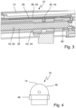
- eine vergrößerte geschnittene Ansicht eines die absolute Wegmesseinrichtung enthaltenden Teils des Antriebs gemäß
Fig. 1 , - Fig. 4
- eine schematische Stirnansicht des im vorliegenden Fall beispielsweise gleichzeitig als Handgriff verwendbaren Antriebs gemäß
Fig. 1 , - Fig. 5
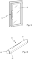
- eine schematische Darstellung eines beispielhaften, mit einem Antrieb gemäß
Fig. 1 versehenen manuell aufgedrehten Flügels, und - Fig. 6
- eine schematische perspektivische Ansicht des beispielsweise gleichzeitig als Handgriff verwendbaren Antriebs gemäß
Fig. 1 . - Die
Figuren 1 bis 6 zeigen eine beispielhafte Ausführungsform eines erfindungsgemäßen Positionier- und/oder Verriegelungsantriebs 10 für einen Flügel 12 (vgl. auchFig. 5 ) eines Fensters, einer Tür oder dergleichen. - Der Antrieb 10 umfasst ein Gehäuse 14, einen eine Antriebseinheit 16 und eine Getriebeeinheit 18 umfassenden Getriebemotor 20, eine elektronische Steuerungseinrichtung 22 zur Ansteuerung des Getriebemotors 20 und ein durch den Getriebemotor 20 beaufschlagbares, mit dem Flügel 12 bzw. einer diesem zugeordneten Verriegelungseinrichtung koppelbaren oder gekoppelten Abtriebselement 24. Die Geschwindigkeit und/oder Position des Abtriebselements 24 ist durch die elektronische Steuerungseinrichtung 22 unter Heranziehung von über eine relative oder inkrementelle Wegmesseinrichtung 26 erfassten jeweiligen relativen Positionen des Abtriebselements 24 steuer- und/oder regelbar.
- Zudem umfasst der Antrieb 10 eine absolute Wegmesseinrichtung 28 zur Erfassung jeweiliger absoluter Positionen des Abtriebselements 24. Dabei ist die relative bzw. inkrementelle Wegmesseinrichtung 26 durch die elektronische Steuerungseinrichtung 22 automatisch über die absolute Wegmesseinrichtung 28 kalibrierbar.
- Die absolute Wegmesseinrichtung 28 ist im vorliegenden Fall auf eine definierte Null-Position bezüglich des Antriebsgehäuses 14 kalibrierbar.
- Die jeweiligen über die relative bzw. inkrementelle Wegmesseinrichtung 26 erfassten relativen Positionen des Abtriebselements 24 werden in einem Zwischenspeicher der elektronischen Steuerungseinrichtung zwischengespeichert.
- Vor der Ausführung eines jeweiligen neuen Befehls kann über die elektronische Steuerungseinrichtung 22 automatisch ein Abgleich zwischen den über die absolute Wegmesseinrichtung 28 erfassten absoluten Positionen und den über die relative bzw. inkrementelle Wegmesseinrichtung 26 erfassten relativen Positionen erfolgen. Dabei übernimmt die elektronische Steuerungseinrichtung 22 bei voneinander abweichenden Positionswerten der absoluten Wegmesseinrichtung 28 und der relativen bzw. inkrementalen Wegmesseinrichtung 26 die Positionswerte der absoluten Wegmesseinrichtung 28 als wahre Positionswerte.
- Erfindungsgemäß erfolgt im Fall eines nach einer jeweiligen Kalibrierung der relativen bzw. inkrementellen Wegmesseinrichtung 26 über die absolute Wegmesseinrichtung 28 auftretenden, eine vorgebbare Zeit andauernden Ausfalls der Spannungsversorgung für die elektronische Steuerungseinrichtung 22, den Getriebemotor 20 und/oder den Zwischenspeicher durch die elektronische Steuerungseinrichtung 22 automatisch ein Abgleich zwischen einem jeweiligen über die absolute Wegmesseinrichtung 28 erfassten absoluten Positionswert und einem jeweiligen im Zwischenspeicher zwischengespeicherten relativen Positionswert.
- Bei einer festgestellten Abweichung zwischen einem jeweiligen über die absolute Wegmesseinrichtung 28 erfassten absoluten Positionswert und einem jeweiligen im Zwischenspeicher zwischengespeicherten relativen Positionswert ist das Abtriebselement 24 über den durch die elektrische Steuerungseinheit 22 ansteuerbaren Getriebemotor 20 automatisch in einen sicheren Zustand entsprechend einem über die absolute Wegmesseinrichtung 20 vorgebbaren absoluten Positionswert überführbar.
- Im Anschluss an die Überführung des Antriebselements 24 in den sicheren Zustand wird der Positionswert der relativen bzw. inkrementellen Wegmesseinrichtung 26 dann auf den Positionswert der absoluten Wegmesseinrichtung 28 gesetzt.
- Die relative bzw. inkrementelle Wegmesseinrichtung 26 und die absolute Wegmesseinrichtung 28 sind im vorliegenden Fall jeweils im Antriebsgehäuse 14 integriert.
- Die Getriebeeinheit 18 des Getriebemotors 20 umfasst im vorliegenden Fall ein Spindelgetriebe 30 mit einer Spindel 32 und einer Spindelmutter 34, dessen Spindel 32 mit einer Abtriebswelle 36 der Antriebseinheit 16 des Getriebemotors 20 verbunden ist und dessen Spindelmutter 34 als Abtriebselement 24 dient. Das die Spindelmutter 34 umfassende Abtriebselement 24 ist im vorliegenden Fall somit mit einer jeweiligen Drehung der Abtriebswelle 36 der Antriebseinheit 16 des Getriebemotors 20 entlang der Spindel 32 verfahrbar.
- Die absolute Wegmesseinrichtung 28 umfasst im vorliegenden Fall ein als Spannungsteiler beschaltetes Potentiometer 38, an dem über einen mit dem Abtriebselement 24 bzw. der Spindelmutter 34 des Spindelgetriebes 30 entlang einer Leiterbahn 40 des Potentiometers 38 verstellbarer Schleifkontakt 42 eine für die jeweilige Position des Abtriebselements 24 bzw. der Spindelmutter 34 repräsentative variable Spannung abgreifbar ist.
- Zum Kalibrieren der absoluten Wegmesseinrichtung 28 ist die Getriebeeinheit 18 mit einem relativ zum Antriebsgehäuse 14 ortsfesten Anschlag 58 für die als Abtriebselement 24 dienende Spindelmutter 34 des Spindelgetriebes 30 versehen.
- Wie insbesondere aus
Fig. 3 ersichtlich, umfasst der Schleifkontakt 42 im vorliegenden Fall eine in der Spindelmutter 34 des Spindelgetriebes 30 gelagerte, federnd gegen die Leiterbahn 40 des Potentiometers 38 gedrückte Kugel 44. Dabei können die Kugel 44 sowie die betreffende Federeinheit zum Anpressen der Kugel 44 an die Leiterbahn 40 gegenüber der als Abtriebselement 44 dienenden Spindelmutter 34 elektrisch isoliert sein. - Die am Potentiometer 38 abgreifbare, für die jeweilige Position des Abtriebselements 24 bzw. der Spindelmutter 34 repräsentative Spannung wird der elektronischen Steuerungseinrichtung 22 beispielsweise über einen (nicht gezeigten) Impedanzwandler zugeführt. Ein solcher Impedanzwandler kann jedoch beispielsweise auch in der elektronischen Steuerungseinrichtung 22 integriert sein.
- Die relative bzw. inkrementale Wegmesseinrichtung 26 kann einen relativ zum Antriebsgehäuse 14 ortsfesten, durch wenigstens einen auf einer Abtriebswelle 36 der Antriebseinheit 16 des Getriebemotors 20 vorgesehenen Magneten beaufschlagbaren Hall-Sensor umfassen. Dabei kann ein solcher Hall-Sensor insbesondere durch einen auf der Abtriebswelle 36 der Antriebseinheit 16 des Getriebemotors 20 vorgesehenen mehrpoligen Magneten, insbesondere einen zweipoligen Magneten mit einem Nord-Pol und einem diesen diametral gegenüberliegenden Süd-Pol, beaufschlagbar sein. Der Hall-Sensor wird in diesem Fall bei rotierender Abtriebswelle 36 der Antriebseinheit 16 abwechselnd mit unterschiedlichen magnetischen Feldern beaufschlagt, was eine durch die elektronische Steuerungseinrichtung 22 erfassbare pulsierende Hall-Spannung mit sich bringt.
- Die Verfahrgeschwindigkeit des Abtriebselements 24 bzw. der Spindelmutter 34 des Spindelgetriebes 30 ist im vorliegenden Fall durch die elektronische Steuerungseinrichtung 22 auf vorgebbare konstante Werte regelbar. Dabei kann die Verfahrgeschwindigkeit des Abtriebselements 24 bzw. der Spindelmutter 34 des Spindelgetriebes 30 zum Verstellen eines Kippflügels zwischen dessen Kipp- und Schließstellung einerseits und zum Verriegeln und Entriegeln eines solchen Kippflügels andererseits auf vorgebbare konstante Werte in unterschiedlichen Bereichen regelbar sein.
- Die Steuerungseinrichtung 22 kann beispielsweise einen Mikrocontroller umfassen.
- Wie insbesondere aus den
Fig. 4 bis 6 ersichtlich, kann das Antriebsgehäuse 14 zur gleichzeitigen Verwendung des am Flügel 12 befestigbaren Antriebs als Handgriff zur manuellen Betätigung des Fensters bzw. der Tür mit einem durch eine Rundung 46 gebildeten Hinterschnitt 48 versehen sein. - Wie insbesondere aus den
Fig. 1 und 2 ersichtlich, kann die elektronische Steuerungseinrichtung 22 beispielsweise über einen Halter oder eine Steuerungsplatine im Antriebsgehäuse 14 montiert sein. Über einen entsprechenden Halter kann zudem ein Bedienfeld 60 in das Antriebsgehäuse 14 eingebracht sein. Über einen Öffnungsindikator 50 kann ein jeweiliger Öffnungszustand des Flügels angezeigt werden. Wie insbesondere ausFig. 2 ersichtlich, kann der Antrieb 10 mit Mitteln 52 zur Feststellung des Flügels in einer bestimmten Drehposition und/oder mit einer Notverriegelung 54 versehen sein. Zudem kann der Antrieb 10 an einem Ende durch eine mit einem Schloss für eine Zugangsberechtigung versehene Seitenkappe 56 verschließbar sein. -
- 10
- Positionier- und/oder Verriegelungsantrieb
- 12
- Flügel
- 14
- Antriebsgehäuse
- 16
- Antriebseinheit
- 18
- Getriebeeinheit
- 20
- Getriebemotor
- 22
- Elektronische Steuerungseinrichtung
- 24
- Abtriebselement
- 26
- Relative bzw. inkrementelle Wegmesseinrichtung
- 28
- Absolute Wegmesseinrichtung
- 30
- Spindelgetriebe
- 32
- Spindel
- 34
- Spindelmutter
- 36
- Abtriebswelle
- 38
- Potentiometer
- 34
- Leiterbahn
- 42
- Schleifkontakt
- 44
- Kugel
- 46
- Rundung
- 48
- Hinterschnitt
- 50
- Öffnungsindikator
- 52
- Feststelleinrichtung
- 54
- Notverriegelung
- 56
- Seitenkappe
- 58
- Anschlag
- 60
- Bedienfeld
Claims (16)
- Positionier- und/oder Verriegelungsantrieb (10) für einen Flügel (12) eines Fensters, einer Tür oder dergleichen, mit einem Gehäuse (14), einem eine Antriebseinheit (16) und eine Getriebeeinheit (18) umfassenden Getriebemotor (20), einer elektronischen Steuerungseinrichtung (22) zur Ansteuerung des Getriebemotors (20) und einem durch den Getriebemotor (20) beaufschlagbaren, mit dem Flügel (12) bzw. einer diesem zugeordneten Verriegelungseinrichtung koppelbaren oder gekoppelten Abtriebselement (24), dessen Geschwindigkeit und/oder Position durch die elektronische Steuerungseinrichtung (22) unter Heranziehung von über eine relative oder inkrementelle Wegmesseinrichtung (26) erfassten jeweiligen relativen Positionen des Abtriebselements (24) steuer- und/oder regelbar ist, wobei der Antrieb (10) zudem eine absolute Wegmesseinrichtung (28) zur Erfassung jeweiliger absoluter Positionen des Abtriebselements (24) umfasst und die relative bzw. inkrementelle Wegmesseinrichtung (26) durch die elektronische Steuerungseinrichtung (22) automatisch über die absolute Wegmesseinrichtung (28) kalibrierbar ist,wobei die jeweiligen über die relative bzw. inkrementelle Wegmesseinrichtung (26) erfassten relativen Positionen des Abtriebselements (24) in einem Zwischenspeicher der elektronischen Steuerungseinrichtung (22) zwischenspeicherbar sind,dadurch gekennzeichnet,dass im Fall eines nach einer jeweiligen Kalibrierung der relativen bzw. inkrementellen Wegmesseinrichtung (26) über die absolute Wegmesseinrichtung (28) auftretenden, eine vorgebbare Zeit andauernden Ausfalls der Spannungsversorgung für die elektronische Steuerungseinrichtung (22), den Getriebemotor (20) und/oder den Zwischenspeicher durch die elektronische Steuerungseinrichtung (22) automatisch ein Abgleich zwischen einem jeweiligen über die absolute Wegmesseinrichtung (28) erfassten absoluten Positionswert und einem jeweiligen im Zwischenspeicher zwischengespeicherten relativen Positionswert erfolgt, dass bei einer festgestellten Abweichung zwischen einem jeweiligen über die absolute Wegmesseinrichtung (28) erfassten absoluten Positionswert und einem jeweiligen im Zwischenspeicher zwischengespeicherten relativen Positionswert das Abtriebselement (24) über den durch die elektronische Steuerungseinheit (22) ansteuerbaren Getriebemotor (20) automatisch in einen sicheren Zustand entsprechend einem über die absolute Wegmesseinrichtung (28) vorgebbaren absoluten Positionswert überführbar ist, unddass der Positionswert der relativen bzw. inkrementellen Wegmesseinrichtung (26) durch die elektronische Steuerungseinrichtung im Anschluss an die Überführung des Antriebselements (24) in den sicheren Zustand auf den erfassten Positionswert der absoluten Wegmesseinrichtung (28) gesetzt wird.
- Antrieb nach Anspruch 1,
dadurch gekennzeichnet,
dass die absolute Wegmesseinrichtung (28) auf eine definierte Null-Position bezüglich des Antriebsgehäuses (14) kalibriert ist. - Antrieb nach einem der vorstehenden Ansprüche,
dadurch gekennzeichnet,
dass über die elektronische Steuerungseinrichtung (22) vor der Ausführung eines jeweiligen neuen Befehls ein Abgleich zwischen den über die absolute Wegmesseinrichtung (28) erfassten absoluten Positionen und den über die relative bzw. inkrementelle Wegmesseinrichtung (26) erfassten relativen Positionen erfolgt. - Antrieb nach Anspruch 3,
dadurch gekennzeichnet,
dass die elektronische Steuerungseinrichtung (22) bei voneinander abweichenden Positionswerten der absoluten Wegmesseinrichtung (28) und der relativen bzw. inkrementellen Wegmesseinrichtung (26) die Positionswerte der absoluten Wegmesseinrichtung (28) als wahre Positionswerte übernimmt. - Antrieb nach einem der vorstehenden Ansprüche,
dadurch gekennzeichnet,
dass die relative bzw. inkrementelle Wegmesseinrichtung (26) und/oder die absolute Wegmesseinrichtung (28) jeweils im Antriebsgehäuse (14) integriert ist. - Antrieb nach einem der vorstehenden Ansprüche,
dadurch gekennzeichnet,
dass die Getriebeeinheit (18) des Getriebemotors (20) ein Spindelgetriebe (30) mit einer Spindel (32) und einer Spindelmutter (34) umfasst, dessen Spindel (32) mit einer Abtriebswelle (36) der Antriebseinheit (16) des Getriebemotors (20) verbunden ist und dessen Spindelmutter (34) als Abtriebselement (24) dient, das somit mit einer jeweiligen Drehung der Abtriebswelle (36) der Antriebseinheit (16) des Getriebemotors (20) entlang der Spindel (32) verfahrbar ist. - Antrieb nach einem der vorstehenden Ansprüche,
dadurch gekennzeichnet,
dass die absolute Wegmesseinrichtung (28) ein als Spannungsteiler beschaltetes Potentiometer (38) umfasst, an dem über einen mit dem Abtriebselement (24) bzw. der Spindelmutter (34) des Spindelgetriebes (30) entlang einer Leiterbahn (40) des Potentiometers (38) verstellbarer Schleifkontakt (42) eine für die jeweilige Position des Abtriebselements (24) bzw. der Spindelmutter (34) repräsentative variable Spannung abgreifbar ist. - Antrieb nach Anspruch 7,
dadurch gekennzeichnet,
dass die Getriebeeinheit (18) zum Kalibrieren der absoluten Wegmesseinrichtung (28) mit einem relativ zum Antriebsgehäuse (14) ortsfesten Anschlag (58) für die als Abtriebselement (24) dienende Spindelmutter (34) des Spindelgetriebes (30) versehen ist. - Antrieb nach Anspruch 7 oder 8,
dadurch gekennzeichnet,
dass der Schleifkontakt (42) eine in der Spindelmutter (34) des Spindelgetriebes (30) gelagerte, federnd gegen die Leiterbahn (40) des Potentiometers (38) gedrückte Kugel (44) umfasst. - Antrieb nach Anspruch 6 und einem der Ansprüche 7-9,
dadurch gekennzeichnet,
dass die am Potentiometer (38) abgreifbare, für die jeweilige Position des Abtriebselements (24) bzw. der Spindelmutter (34) repräsentative Spannung der elektronischen Steuerungseinrichtung (22) über einen Impedanzwandler zuführbar ist. - Antrieb nach einem der vorstehenden Ansprüche,
dadurch gekennzeichnet,
dass die relative bzw. inkrementelle Wegmesseinrichtung (26) einen relativ zum Antriebsgehäuse (14) ortsfesten, durch wenigstens einen auf einer Abtriebswelle (36) der Antriebseinheit (16) des Getriebemotors (20) vorgesehenen Magneten beaufschlagen Hall-Sensor umfasst. - Antrieb nach Anspruch 11,
dadurch gekennzeichnet,
dass der Hall-Sensor durch einen auf der Abtriebswelle (36) der Antriebseinheit (16) des Getriebemotors (20) vorgesehenen mehrpoligen Magneten, insbesondere einen zweipoligen Magneten mit einem Nord-Pol und einem diesem diametral gegenüberliegenden Süd-Pol, beaufschlagbar ist. - Antrieb nach einem der vorstehenden Ansprüche,
dadurch gekennzeichnet,
dass die Verfahrgeschwindigkeit des Abtriebselements (24) bzw. der Spindelmutter (34) des Spindelgetriebes (30) durch die elektronische Steuerungseinrichtung (22) auf vorgebbare konstante Werte regelbar ist. - Antrieb nach Anspruch 13,
dadurch gekennzeichnet,
dass die Verfahrgeschwindigkeit des Abtriebselements (24) bzw. der Spindelmutter (34) des Spindelgetriebes (30) zum Verstellen eines Kippflügels zwischen dessen Kipp- und Schließstellung einerseits und zum Verriegeln und Entriegeln eines solchen Kippflügels andererseits auf vorgebbare konstante Werte in unterschiedlichen Bereichen regelbar ist. - Antrieb nach einem der vorstehenden Ansprüche,
dadurch gekennzeichnet,
dass die Steuerungseinrichtung (22) einen Mikrocontroller umfasst. - Antrieb nach einem der vorstehenden Ansprüche,
dadurch gekennzeichnet,
dass das Antriebsgehäuse (14) zur gleichzeitigen Verwendung des am Flügel (12) befestigbaren Antriebs (10) als Handgriff zur manuellen Betätigung des Fensters bzw. der Tür mit einem durch eine Rundung (46) gebildeten Hinterschnitt (48) versehen ist.
Applications Claiming Priority (1)
| Application Number | Priority Date | Filing Date | Title |
|---|---|---|---|
| DE102019209378.7A DE102019209378A1 (de) | 2019-06-27 | 2019-06-27 | Antrieb für einen Fenster- oder Türflügel |
Publications (2)
| Publication Number | Publication Date |
|---|---|
| EP3757330A1 EP3757330A1 (de) | 2020-12-30 |
| EP3757330B1 true EP3757330B1 (de) | 2023-07-26 |
Family
ID=69960570
Family Applications (1)
| Application Number | Title | Priority Date | Filing Date |
|---|---|---|---|
| EP20165501.6A Active EP3757330B1 (de) | 2019-06-27 | 2020-03-25 | Antrieb für einen fenster- oder türflügel |
Country Status (4)
| Country | Link |
|---|---|
| EP (1) | EP3757330B1 (de) |
| CN (1) | CN112145015A (de) |
| DE (1) | DE102019209378A1 (de) |
| PL (1) | PL3757330T3 (de) |
Family Cites Families (17)
| Publication number | Priority date | Publication date | Assignee | Title |
|---|---|---|---|---|
| DE3829405A1 (de) * | 1988-08-30 | 1990-03-08 | Webasto Ag Fahrzeugtechnik | Betaetigungseinrichtung fuer elektromotorisch bewegbare teile von kraftfahrzeugen |
| DE3915569A1 (de) * | 1989-05-12 | 1990-11-15 | Winkhaus Fa August | Fenstersystem fuer ein gebaeude |
| US5187993A (en) * | 1991-08-12 | 1993-02-23 | Addco Manufacturing, Inc. | Actuator for remote control |
| DE29802104U1 (de) * | 1997-12-18 | 1999-04-22 | Steinel Ag, Einsiedeln | Betätigungsvorrichtung für einen Tür- oder Fensterflügel |
| DE50110050D1 (de) * | 2000-07-05 | 2006-07-20 | Hoermann Kg Antriebstechnik | Gebäude- oder geländeabschluss, antriebsvorrichtung zum antreiben eines flügels desselben sowie steuerverfahren dafür |
| AT506196B1 (de) * | 2007-12-19 | 2010-10-15 | Blum Gmbh Julius | Stellmechanismus zum bewegen einer hochbewegbaren klappe eines möbels |
| CN201215488Y (zh) * | 2008-05-27 | 2009-04-01 | 上海精浦机电有限公司 | 绝对值与增量信号双输出的编码器 |
| JP5150450B2 (ja) * | 2008-10-27 | 2013-02-20 | 株式会社豊田自動織機 | 車両用樹脂ウインドウの支持構造 |
| DE202008016763U1 (de) * | 2008-12-18 | 2010-05-20 | Mfz Antriebe Gmbh & Co. Kg | Überwachungsvorrichtung für ein Öffnungsabschlusssystem, Antriebseinheit für ein Öffnungsabschlusssystem sowie Öffnungsabschlusssystem |
| US8624564B2 (en) * | 2010-12-23 | 2014-01-07 | Caterpillar Inc. | Switched reluctance generator initial rotor position estimation |
| CN102355183B (zh) * | 2011-09-26 | 2013-11-13 | 东华大学 | 一种pet-ct机轮毂电机轮毂的位置检测方法 |
| CN103185625A (zh) * | 2012-11-03 | 2013-07-03 | 刘万更 | 光纤半绝对值编码器 |
| CN103397828B (zh) * | 2013-07-19 | 2016-06-01 | 马夸特开关(上海)有限公司 | 电动车窗开关防夹系统 |
| DE202013104858U1 (de) * | 2013-10-30 | 2015-02-02 | Aumüller Aumatic GmbH | Antriebsvorrichtung |
| US10161175B2 (en) * | 2016-02-29 | 2018-12-25 | Ford Global Technologies, Llc | Moving object detection for power door system |
| CN109381216B (zh) * | 2017-08-08 | 2023-08-01 | 通用电气公司 | 患者移动床板的运动控制装置及方法、计算机程序 |
| CN107443381B (zh) * | 2017-09-05 | 2020-08-04 | 中科新松有限公司 | 一种弹性驱动关节的力矩寻零方法 |
-
2019
- 2019-06-27 DE DE102019209378.7A patent/DE102019209378A1/de not_active Ceased
-
2020
- 2020-03-25 EP EP20165501.6A patent/EP3757330B1/de active Active
- 2020-03-25 PL PL20165501.6T patent/PL3757330T3/pl unknown
- 2020-05-21 CN CN202010433891.5A patent/CN112145015A/zh active Pending
Also Published As
| Publication number | Publication date |
|---|---|
| PL3757330T3 (pl) | 2024-01-15 |
| CN112145015A (zh) | 2020-12-29 |
| DE102019209378A1 (de) | 2020-12-31 |
| EP3757330A1 (de) | 2020-12-30 |
Similar Documents
| Publication | Publication Date | Title |
|---|---|---|
| EP1157256B1 (de) | Längenmesssystem mit mindestens einem magnetischen massstab | |
| DE19911483C2 (de) | Fensterhebervorrichtung mit Sicherheitseinrichtung | |
| DE3829405A1 (de) | Betaetigungseinrichtung fuer elektromotorisch bewegbare teile von kraftfahrzeugen | |
| DE10047793A1 (de) | Rotationsrheometer | |
| WO2009053138A1 (de) | Verfahren und vorrichtung zur erhöhung der genauigkeit der positionsbestimmung eines motorgetriebenen schliessteiles eines fahrzeugs | |
| EP1722060B1 (de) | Funktionseinheit eines Kraftfahrzeugs | |
| DE3921158C2 (de) | ||
| EP0349792A1 (de) | Positionslesesystem für über 360o verschwenkbare Werkzeugmaschinenteile | |
| EP3757330A1 (de) | Antrieb für einen fenster- oder türflügel | |
| DE102004007400B4 (de) | Verriegelungssystem | |
| DE10164580C1 (de) | Anordnung zum Erfassen der aktuellen Länge eines elektromechanischen Linearantriebs | |
| EP0650107A1 (de) | Steuersystem für motorische Antriebe | |
| WO2017137191A1 (de) | Sensoreinrichtung zum erfassen einer magnetfeldänderung sowie verfahren zum abgleichen einer solchen sensoreinrichtung | |
| DE102007055098B4 (de) | Erfassungsanordnung | |
| DE4438851C2 (de) | Vorrichtung zur Steuerung eines motorischen Antriebes | |
| DE1916525A1 (de) | Vorrichtung zur Messung des Drehwinkels eines verdrehbaren Gegenstandes | |
| DE102011116910A1 (de) | Vorrichtung zur Erfassung von Drehwinkeln einer Welle größer als 360° | |
| EP4294700A1 (de) | Drehwinkelsensoranordnung und lenksystem für ein fahrzeug | |
| DE19610877A1 (de) | Vorrichtung zur Steuerung eines Antriebes für Rolläden, Rolltore o. dgl. | |
| EP1007908A1 (de) | Drehwinkelgeber | |
| DE102014115673A1 (de) | Antriebsvorrichtung und Antriebsverfahren | |
| DE102014105089B4 (de) | Antriebsvorrichtung für ein Flächenelement | |
| DE102024208614A1 (de) | Verfahren sowie Vorrichtung zum Betreiben eines elektrischen Verstellmechanismus | |
| DE202006020897U1 (de) | Positionsmelder für die Steuerung von bewegbaren Elementen | |
| EP1297235A1 (de) | Gebäude- oder geländeabschluss, antriebsvorrichtung zum antreiben eines flügels desselben sowie steuerverfahren dafür |
Legal Events
| Date | Code | Title | Description |
|---|---|---|---|
| PUAI | Public reference made under article 153(3) epc to a published international application that has entered the european phase |
Free format text: ORIGINAL CODE: 0009012 |
|
| STAA | Information on the status of an ep patent application or granted ep patent |
Free format text: STATUS: THE APPLICATION HAS BEEN PUBLISHED |
|
| AK | Designated contracting states |
Kind code of ref document: A1 Designated state(s): AL AT BE BG CH CY CZ DE DK EE ES FI FR GB GR HR HU IE IS IT LI LT LU LV MC MK MT NL NO PL PT RO RS SE SI SK SM TR |
|
| AX | Request for extension of the european patent |
Extension state: BA ME |
|
| STAA | Information on the status of an ep patent application or granted ep patent |
Free format text: STATUS: REQUEST FOR EXAMINATION WAS MADE |
|
| 17P | Request for examination filed |
Effective date: 20210610 |
|
| RBV | Designated contracting states (corrected) |
Designated state(s): AL AT BE BG CH CY CZ DE DK EE ES FI FR GB GR HR HU IE IS IT LI LT LU LV MC MK MT NL NO PL PT RO RS SE SI SK SM TR |
|
| STAA | Information on the status of an ep patent application or granted ep patent |
Free format text: STATUS: EXAMINATION IS IN PROGRESS |
|
| 17Q | First examination report despatched |
Effective date: 20220311 |
|
| GRAP | Despatch of communication of intention to grant a patent |
Free format text: ORIGINAL CODE: EPIDOSNIGR1 |
|
| STAA | Information on the status of an ep patent application or granted ep patent |
Free format text: STATUS: GRANT OF PATENT IS INTENDED |
|
| INTG | Intention to grant announced |
Effective date: 20230316 |
|
| GRAS | Grant fee paid |
Free format text: ORIGINAL CODE: EPIDOSNIGR3 |
|
| P01 | Opt-out of the competence of the unified patent court (upc) registered |
Effective date: 20230510 |
|
| GRAA | (expected) grant |
Free format text: ORIGINAL CODE: 0009210 |
|
| STAA | Information on the status of an ep patent application or granted ep patent |
Free format text: STATUS: THE PATENT HAS BEEN GRANTED |
|
| AK | Designated contracting states |
Kind code of ref document: B1 Designated state(s): AL AT BE BG CH CY CZ DE DK EE ES FI FR GB GR HR HU IE IS IT LI LT LU LV MC MK MT NL NO PL PT RO RS SE SI SK SM TR |
|
| REG | Reference to a national code |
Ref country code: CH Ref legal event code: EP |
|
| REG | Reference to a national code |
Ref country code: IE Ref legal event code: FG4D Free format text: LANGUAGE OF EP DOCUMENT: GERMAN |
|
| REG | Reference to a national code |
Ref country code: DE Ref legal event code: R096 Ref document number: 502020004325 Country of ref document: DE |
|
| REG | Reference to a national code |
Ref country code: LT Ref legal event code: MG9D |
|
| REG | Reference to a national code |
Ref country code: NL Ref legal event code: MP Effective date: 20230726 |
|
| PG25 | Lapsed in a contracting state [announced via postgrant information from national office to epo] |
Ref country code: NL Free format text: LAPSE BECAUSE OF FAILURE TO SUBMIT A TRANSLATION OF THE DESCRIPTION OR TO PAY THE FEE WITHIN THE PRESCRIBED TIME-LIMIT Effective date: 20230726 |
|
| PG25 | Lapsed in a contracting state [announced via postgrant information from national office to epo] |
Ref country code: GR Free format text: LAPSE BECAUSE OF FAILURE TO SUBMIT A TRANSLATION OF THE DESCRIPTION OR TO PAY THE FEE WITHIN THE PRESCRIBED TIME-LIMIT Effective date: 20231027 |
|
| PG25 | Lapsed in a contracting state [announced via postgrant information from national office to epo] |
Ref country code: IS Free format text: LAPSE BECAUSE OF FAILURE TO SUBMIT A TRANSLATION OF THE DESCRIPTION OR TO PAY THE FEE WITHIN THE PRESCRIBED TIME-LIMIT Effective date: 20231126 |
|
| PG25 | Lapsed in a contracting state [announced via postgrant information from national office to epo] |
Ref country code: SE Free format text: LAPSE BECAUSE OF FAILURE TO SUBMIT A TRANSLATION OF THE DESCRIPTION OR TO PAY THE FEE WITHIN THE PRESCRIBED TIME-LIMIT Effective date: 20230726 Ref country code: RS Free format text: LAPSE BECAUSE OF FAILURE TO SUBMIT A TRANSLATION OF THE DESCRIPTION OR TO PAY THE FEE WITHIN THE PRESCRIBED TIME-LIMIT Effective date: 20230726 Ref country code: PT Free format text: LAPSE BECAUSE OF FAILURE TO SUBMIT A TRANSLATION OF THE DESCRIPTION OR TO PAY THE FEE WITHIN THE PRESCRIBED TIME-LIMIT Effective date: 20231127 Ref country code: NO Free format text: LAPSE BECAUSE OF FAILURE TO SUBMIT A TRANSLATION OF THE DESCRIPTION OR TO PAY THE FEE WITHIN THE PRESCRIBED TIME-LIMIT Effective date: 20231026 Ref country code: LV Free format text: LAPSE BECAUSE OF FAILURE TO SUBMIT A TRANSLATION OF THE DESCRIPTION OR TO PAY THE FEE WITHIN THE PRESCRIBED TIME-LIMIT Effective date: 20230726 Ref country code: LT Free format text: LAPSE BECAUSE OF FAILURE TO SUBMIT A TRANSLATION OF THE DESCRIPTION OR TO PAY THE FEE WITHIN THE PRESCRIBED TIME-LIMIT Effective date: 20230726 Ref country code: IS Free format text: LAPSE BECAUSE OF FAILURE TO SUBMIT A TRANSLATION OF THE DESCRIPTION OR TO PAY THE FEE WITHIN THE PRESCRIBED TIME-LIMIT Effective date: 20231126 Ref country code: HR Free format text: LAPSE BECAUSE OF FAILURE TO SUBMIT A TRANSLATION OF THE DESCRIPTION OR TO PAY THE FEE WITHIN THE PRESCRIBED TIME-LIMIT Effective date: 20230726 Ref country code: GR Free format text: LAPSE BECAUSE OF FAILURE TO SUBMIT A TRANSLATION OF THE DESCRIPTION OR TO PAY THE FEE WITHIN THE PRESCRIBED TIME-LIMIT Effective date: 20231027 Ref country code: FI Free format text: LAPSE BECAUSE OF FAILURE TO SUBMIT A TRANSLATION OF THE DESCRIPTION OR TO PAY THE FEE WITHIN THE PRESCRIBED TIME-LIMIT Effective date: 20230726 |
|
| PG25 | Lapsed in a contracting state [announced via postgrant information from national office to epo] |
Ref country code: ES Free format text: LAPSE BECAUSE OF FAILURE TO SUBMIT A TRANSLATION OF THE DESCRIPTION OR TO PAY THE FEE WITHIN THE PRESCRIBED TIME-LIMIT Effective date: 20230726 |
|
| REG | Reference to a national code |
Ref country code: DE Ref legal event code: R097 Ref document number: 502020004325 Country of ref document: DE |
|
| PG25 | Lapsed in a contracting state [announced via postgrant information from national office to epo] |
Ref country code: SM Free format text: LAPSE BECAUSE OF FAILURE TO SUBMIT A TRANSLATION OF THE DESCRIPTION OR TO PAY THE FEE WITHIN THE PRESCRIBED TIME-LIMIT Effective date: 20230726 Ref country code: RO Free format text: LAPSE BECAUSE OF FAILURE TO SUBMIT A TRANSLATION OF THE DESCRIPTION OR TO PAY THE FEE WITHIN THE PRESCRIBED TIME-LIMIT Effective date: 20230726 Ref country code: ES Free format text: LAPSE BECAUSE OF FAILURE TO SUBMIT A TRANSLATION OF THE DESCRIPTION OR TO PAY THE FEE WITHIN THE PRESCRIBED TIME-LIMIT Effective date: 20230726 Ref country code: EE Free format text: LAPSE BECAUSE OF FAILURE TO SUBMIT A TRANSLATION OF THE DESCRIPTION OR TO PAY THE FEE WITHIN THE PRESCRIBED TIME-LIMIT Effective date: 20230726 Ref country code: DK Free format text: LAPSE BECAUSE OF FAILURE TO SUBMIT A TRANSLATION OF THE DESCRIPTION OR TO PAY THE FEE WITHIN THE PRESCRIBED TIME-LIMIT Effective date: 20230726 Ref country code: CZ Free format text: LAPSE BECAUSE OF FAILURE TO SUBMIT A TRANSLATION OF THE DESCRIPTION OR TO PAY THE FEE WITHIN THE PRESCRIBED TIME-LIMIT Effective date: 20230726 Ref country code: SK Free format text: LAPSE BECAUSE OF FAILURE TO SUBMIT A TRANSLATION OF THE DESCRIPTION OR TO PAY THE FEE WITHIN THE PRESCRIBED TIME-LIMIT Effective date: 20230726 |
|
| PG25 | Lapsed in a contracting state [announced via postgrant information from national office to epo] |
Ref country code: IT Free format text: LAPSE BECAUSE OF FAILURE TO SUBMIT A TRANSLATION OF THE DESCRIPTION OR TO PAY THE FEE WITHIN THE PRESCRIBED TIME-LIMIT Effective date: 20230726 |
|
| PLBE | No opposition filed within time limit |
Free format text: ORIGINAL CODE: 0009261 |
|
| STAA | Information on the status of an ep patent application or granted ep patent |
Free format text: STATUS: NO OPPOSITION FILED WITHIN TIME LIMIT |
|
| 26N | No opposition filed |
Effective date: 20240429 |
|
| PG25 | Lapsed in a contracting state [announced via postgrant information from national office to epo] |
Ref country code: SI Free format text: LAPSE BECAUSE OF FAILURE TO SUBMIT A TRANSLATION OF THE DESCRIPTION OR TO PAY THE FEE WITHIN THE PRESCRIBED TIME-LIMIT Effective date: 20230726 |
|
| REG | Reference to a national code |
Ref country code: CH Ref legal event code: PL |
|
| PG25 | Lapsed in a contracting state [announced via postgrant information from national office to epo] |
Ref country code: BG Free format text: LAPSE BECAUSE OF FAILURE TO SUBMIT A TRANSLATION OF THE DESCRIPTION OR TO PAY THE FEE WITHIN THE PRESCRIBED TIME-LIMIT Effective date: 20230726 |
|
| PG25 | Lapsed in a contracting state [announced via postgrant information from national office to epo] |
Ref country code: LU Free format text: LAPSE BECAUSE OF NON-PAYMENT OF DUE FEES Effective date: 20240325 |
|
| PG25 | Lapsed in a contracting state [announced via postgrant information from national office to epo] |
Ref country code: MC Free format text: LAPSE BECAUSE OF FAILURE TO SUBMIT A TRANSLATION OF THE DESCRIPTION OR TO PAY THE FEE WITHIN THE PRESCRIBED TIME-LIMIT Effective date: 20230726 |
|
| GBPC | Gb: european patent ceased through non-payment of renewal fee |
Effective date: 20240325 |
|
| PG25 | Lapsed in a contracting state [announced via postgrant information from national office to epo] |
Ref country code: MC Free format text: LAPSE BECAUSE OF FAILURE TO SUBMIT A TRANSLATION OF THE DESCRIPTION OR TO PAY THE FEE WITHIN THE PRESCRIBED TIME-LIMIT Effective date: 20230726 Ref country code: LU Free format text: LAPSE BECAUSE OF NON-PAYMENT OF DUE FEES Effective date: 20240325 Ref country code: BG Free format text: LAPSE BECAUSE OF FAILURE TO SUBMIT A TRANSLATION OF THE DESCRIPTION OR TO PAY THE FEE WITHIN THE PRESCRIBED TIME-LIMIT Effective date: 20230726 |
|
| REG | Reference to a national code |
Ref country code: BE Ref legal event code: MM Effective date: 20240331 |
|
| PG25 | Lapsed in a contracting state [announced via postgrant information from national office to epo] |
Ref country code: BE Free format text: LAPSE BECAUSE OF NON-PAYMENT OF DUE FEES Effective date: 20240331 |
|
| PG25 | Lapsed in a contracting state [announced via postgrant information from national office to epo] |
Ref country code: GB Free format text: LAPSE BECAUSE OF NON-PAYMENT OF DUE FEES Effective date: 20240325 |
|
| PG25 | Lapsed in a contracting state [announced via postgrant information from national office to epo] |
Ref country code: FR Free format text: LAPSE BECAUSE OF NON-PAYMENT OF DUE FEES Effective date: 20240331 |
|
| PG25 | Lapsed in a contracting state [announced via postgrant information from national office to epo] |
Ref country code: IE Free format text: LAPSE BECAUSE OF NON-PAYMENT OF DUE FEES Effective date: 20240325 |
|
| PG25 | Lapsed in a contracting state [announced via postgrant information from national office to epo] |
Ref country code: IE Free format text: LAPSE BECAUSE OF NON-PAYMENT OF DUE FEES Effective date: 20240325 Ref country code: GB Free format text: LAPSE BECAUSE OF NON-PAYMENT OF DUE FEES Effective date: 20240325 Ref country code: FR Free format text: LAPSE BECAUSE OF NON-PAYMENT OF DUE FEES Effective date: 20240331 Ref country code: BE Free format text: LAPSE BECAUSE OF NON-PAYMENT OF DUE FEES Effective date: 20240331 Ref country code: CH Free format text: LAPSE BECAUSE OF NON-PAYMENT OF DUE FEES Effective date: 20240331 |
|
| PG25 | Lapsed in a contracting state [announced via postgrant information from national office to epo] |
Ref country code: CY Free format text: LAPSE BECAUSE OF FAILURE TO SUBMIT A TRANSLATION OF THE DESCRIPTION OR TO PAY THE FEE WITHIN THE PRESCRIBED TIME-LIMIT; INVALID AB INITIO Effective date: 20200325 |
|
| PG25 | Lapsed in a contracting state [announced via postgrant information from national office to epo] |
Ref country code: HU Free format text: LAPSE BECAUSE OF FAILURE TO SUBMIT A TRANSLATION OF THE DESCRIPTION OR TO PAY THE FEE WITHIN THE PRESCRIBED TIME-LIMIT; INVALID AB INITIO Effective date: 20200325 |
|
| PG25 | Lapsed in a contracting state [announced via postgrant information from national office to epo] |
Ref country code: TR Free format text: LAPSE BECAUSE OF FAILURE TO SUBMIT A TRANSLATION OF THE DESCRIPTION OR TO PAY THE FEE WITHIN THE PRESCRIBED TIME-LIMIT Effective date: 20230726 |
|
| PGFP | Annual fee paid to national office [announced via postgrant information from national office to epo] |
Ref country code: DE Payment date: 20260331 Year of fee payment: 7 |
|
| PGFP | Annual fee paid to national office [announced via postgrant information from national office to epo] |
Ref country code: AT Payment date: 20260320 Year of fee payment: 7 |
|
| PGFP | Annual fee paid to national office [announced via postgrant information from national office to epo] |
Ref country code: PL Payment date: 20260313 Year of fee payment: 7 |