EP3756936A1 - System and method for controlling relay using flip-flop - Google Patents
System and method for controlling relay using flip-flop Download PDFInfo
- Publication number
- EP3756936A1 EP3756936A1 EP19864453.6A EP19864453A EP3756936A1 EP 3756936 A1 EP3756936 A1 EP 3756936A1 EP 19864453 A EP19864453 A EP 19864453A EP 3756936 A1 EP3756936 A1 EP 3756936A1
- Authority
- EP
- European Patent Office
- Prior art keywords
- clock signal
- relay
- signal
- flip
- flop
- Prior art date
- Legal status (The legal status is an assumption and is not a legal conclusion. Google has not performed a legal analysis and makes no representation as to the accuracy of the status listed.)
- Granted
Links
- 238000000034 method Methods 0.000 title claims abstract description 22
- 230000006854 communication Effects 0.000 claims description 53
- 238000004891 communication Methods 0.000 claims description 53
- 239000004065 semiconductor Substances 0.000 claims description 6
- 230000005669 field effect Effects 0.000 claims description 3
- 229910044991 metal oxide Inorganic materials 0.000 claims description 3
- 150000004706 metal oxides Chemical class 0.000 claims description 3
- 238000012544 monitoring process Methods 0.000 abstract description 4
- 238000010586 diagram Methods 0.000 description 6
- 230000007175 bidirectional communication Effects 0.000 description 2
- 239000000470 constituent Substances 0.000 description 2
- 230000010485 coping Effects 0.000 description 2
- 230000000694 effects Effects 0.000 description 1
- 238000004146 energy storage Methods 0.000 description 1
- 230000007717 exclusion Effects 0.000 description 1
- 230000002093 peripheral effect Effects 0.000 description 1
Images


Classifications
-
- B—PERFORMING OPERATIONS; TRANSPORTING
- B60—VEHICLES IN GENERAL
- B60L—PROPULSION OF ELECTRICALLY-PROPELLED VEHICLES; SUPPLYING ELECTRIC POWER FOR AUXILIARY EQUIPMENT OF ELECTRICALLY-PROPELLED VEHICLES; ELECTRODYNAMIC BRAKE SYSTEMS FOR VEHICLES IN GENERAL; MAGNETIC SUSPENSION OR LEVITATION FOR VEHICLES; MONITORING OPERATING VARIABLES OF ELECTRICALLY-PROPELLED VEHICLES; ELECTRIC SAFETY DEVICES FOR ELECTRICALLY-PROPELLED VEHICLES
- B60L58/00—Methods or circuit arrangements for monitoring or controlling batteries or fuel cells, specially adapted for electric vehicles
- B60L58/10—Methods or circuit arrangements for monitoring or controlling batteries or fuel cells, specially adapted for electric vehicles for monitoring or controlling batteries
-
- B—PERFORMING OPERATIONS; TRANSPORTING
- B60—VEHICLES IN GENERAL
- B60L—PROPULSION OF ELECTRICALLY-PROPELLED VEHICLES; SUPPLYING ELECTRIC POWER FOR AUXILIARY EQUIPMENT OF ELECTRICALLY-PROPELLED VEHICLES; ELECTRODYNAMIC BRAKE SYSTEMS FOR VEHICLES IN GENERAL; MAGNETIC SUSPENSION OR LEVITATION FOR VEHICLES; MONITORING OPERATING VARIABLES OF ELECTRICALLY-PROPELLED VEHICLES; ELECTRIC SAFETY DEVICES FOR ELECTRICALLY-PROPELLED VEHICLES
- B60L3/00—Electric devices on electrically-propelled vehicles for safety purposes; Monitoring operating variables, e.g. speed, deceleration or energy consumption
- B60L3/0007—Measures or means for preventing or attenuating collisions
- B60L3/0015—Prevention of collisions
-
- B—PERFORMING OPERATIONS; TRANSPORTING
- B60—VEHICLES IN GENERAL
- B60L—PROPULSION OF ELECTRICALLY-PROPELLED VEHICLES; SUPPLYING ELECTRIC POWER FOR AUXILIARY EQUIPMENT OF ELECTRICALLY-PROPELLED VEHICLES; ELECTRODYNAMIC BRAKE SYSTEMS FOR VEHICLES IN GENERAL; MAGNETIC SUSPENSION OR LEVITATION FOR VEHICLES; MONITORING OPERATING VARIABLES OF ELECTRICALLY-PROPELLED VEHICLES; ELECTRIC SAFETY DEVICES FOR ELECTRICALLY-PROPELLED VEHICLES
- B60L3/00—Electric devices on electrically-propelled vehicles for safety purposes; Monitoring operating variables, e.g. speed, deceleration or energy consumption
- B60L3/0023—Detecting, eliminating, remedying or compensating for drive train abnormalities, e.g. failures within the drive train
- B60L3/0046—Detecting, eliminating, remedying or compensating for drive train abnormalities, e.g. failures within the drive train relating to electric energy storage systems, e.g. batteries or capacitors
-
- B—PERFORMING OPERATIONS; TRANSPORTING
- B60—VEHICLES IN GENERAL
- B60L—PROPULSION OF ELECTRICALLY-PROPELLED VEHICLES; SUPPLYING ELECTRIC POWER FOR AUXILIARY EQUIPMENT OF ELECTRICALLY-PROPELLED VEHICLES; ELECTRODYNAMIC BRAKE SYSTEMS FOR VEHICLES IN GENERAL; MAGNETIC SUSPENSION OR LEVITATION FOR VEHICLES; MONITORING OPERATING VARIABLES OF ELECTRICALLY-PROPELLED VEHICLES; ELECTRIC SAFETY DEVICES FOR ELECTRICALLY-PROPELLED VEHICLES
- B60L50/00—Electric propulsion with power supplied within the vehicle
- B60L50/50—Electric propulsion with power supplied within the vehicle using propulsion power supplied by batteries or fuel cells
- B60L50/60—Electric propulsion with power supplied within the vehicle using propulsion power supplied by batteries or fuel cells using power supplied by batteries
-
- B—PERFORMING OPERATIONS; TRANSPORTING
- B60—VEHICLES IN GENERAL
- B60L—PROPULSION OF ELECTRICALLY-PROPELLED VEHICLES; SUPPLYING ELECTRIC POWER FOR AUXILIARY EQUIPMENT OF ELECTRICALLY-PROPELLED VEHICLES; ELECTRODYNAMIC BRAKE SYSTEMS FOR VEHICLES IN GENERAL; MAGNETIC SUSPENSION OR LEVITATION FOR VEHICLES; MONITORING OPERATING VARIABLES OF ELECTRICALLY-PROPELLED VEHICLES; ELECTRIC SAFETY DEVICES FOR ELECTRICALLY-PROPELLED VEHICLES
- B60L53/00—Methods of charging batteries, specially adapted for electric vehicles; Charging stations or on-board charging equipment therefor; Exchange of energy storage elements in electric vehicles
-
- B—PERFORMING OPERATIONS; TRANSPORTING
- B60—VEHICLES IN GENERAL
- B60L—PROPULSION OF ELECTRICALLY-PROPELLED VEHICLES; SUPPLYING ELECTRIC POWER FOR AUXILIARY EQUIPMENT OF ELECTRICALLY-PROPELLED VEHICLES; ELECTRODYNAMIC BRAKE SYSTEMS FOR VEHICLES IN GENERAL; MAGNETIC SUSPENSION OR LEVITATION FOR VEHICLES; MONITORING OPERATING VARIABLES OF ELECTRICALLY-PROPELLED VEHICLES; ELECTRIC SAFETY DEVICES FOR ELECTRICALLY-PROPELLED VEHICLES
- B60L2240/00—Control parameters of input or output; Target parameters
- B60L2240/40—Drive Train control parameters
- B60L2240/54—Drive Train control parameters related to batteries
- B60L2240/547—Voltage
-
- B—PERFORMING OPERATIONS; TRANSPORTING
- B60—VEHICLES IN GENERAL
- B60L—PROPULSION OF ELECTRICALLY-PROPELLED VEHICLES; SUPPLYING ELECTRIC POWER FOR AUXILIARY EQUIPMENT OF ELECTRICALLY-PROPELLED VEHICLES; ELECTRODYNAMIC BRAKE SYSTEMS FOR VEHICLES IN GENERAL; MAGNETIC SUSPENSION OR LEVITATION FOR VEHICLES; MONITORING OPERATING VARIABLES OF ELECTRICALLY-PROPELLED VEHICLES; ELECTRIC SAFETY DEVICES FOR ELECTRICALLY-PROPELLED VEHICLES
- B60L2240/00—Control parameters of input or output; Target parameters
- B60L2240/80—Time limits
-
- B—PERFORMING OPERATIONS; TRANSPORTING
- B60—VEHICLES IN GENERAL
- B60Y—INDEXING SCHEME RELATING TO ASPECTS CROSS-CUTTING VEHICLE TECHNOLOGY
- B60Y2200/00—Type of vehicle
- B60Y2200/90—Vehicles comprising electric prime movers
- B60Y2200/91—Electric vehicles
-
- Y—GENERAL TAGGING OF NEW TECHNOLOGICAL DEVELOPMENTS; GENERAL TAGGING OF CROSS-SECTIONAL TECHNOLOGIES SPANNING OVER SEVERAL SECTIONS OF THE IPC; TECHNICAL SUBJECTS COVERED BY FORMER USPC CROSS-REFERENCE ART COLLECTIONS [XRACs] AND DIGESTS
- Y02—TECHNOLOGIES OR APPLICATIONS FOR MITIGATION OR ADAPTATION AGAINST CLIMATE CHANGE
- Y02T—CLIMATE CHANGE MITIGATION TECHNOLOGIES RELATED TO TRANSPORTATION
- Y02T10/00—Road transport of goods or passengers
- Y02T10/60—Other road transportation technologies with climate change mitigation effect
- Y02T10/7072—Electromobility specific charging systems or methods for batteries, ultracapacitors, supercapacitors or double-layer capacitors
-
- Y—GENERAL TAGGING OF NEW TECHNOLOGICAL DEVELOPMENTS; GENERAL TAGGING OF CROSS-SECTIONAL TECHNOLOGIES SPANNING OVER SEVERAL SECTIONS OF THE IPC; TECHNICAL SUBJECTS COVERED BY FORMER USPC CROSS-REFERENCE ART COLLECTIONS [XRACs] AND DIGESTS
- Y02—TECHNOLOGIES OR APPLICATIONS FOR MITIGATION OR ADAPTATION AGAINST CLIMATE CHANGE
- Y02T—CLIMATE CHANGE MITIGATION TECHNOLOGIES RELATED TO TRANSPORTATION
- Y02T90/00—Enabling technologies or technologies with a potential or indirect contribution to GHG emissions mitigation
- Y02T90/10—Technologies relating to charging of electric vehicles
- Y02T90/14—Plug-in electric vehicles
Definitions
- the present invention relates to a system and a method for controlling a relay using a flip-flop, and particularly, to a system and a method for controlling a relay using a flip-flop, which install a flip-flop controlling a relay by receiving a signal of a control unit in a battery management system of a vehicle and supply flip-flop operation power to the flip-flop through a monitoring circuit connected to a battery of the vehicle even when an operation power of the battery management system of the vehicle is interrupted to maintain a closing state of a relay controlling driving power of the vehicle and conserve power of the vehicle for a predetermined time.
- a secondary battery which is high in application easiness according to a product group and has electrical characteristics including high energy density, and the like is universally applied to an electric vehicle (EV) driven by an electric driving source, a hybrid vehicle (HV) or an energy storage system (ESS) or an uninterruptible power supply (UPS) system using a medium/large battery used for a house or an industry as well as a portable device.
- EV electric vehicle
- HV hybrid vehicle
- ESS energy storage system
- UPS uninterruptible power supply
- Future trends of an automotive industry using the secondary battery may be greatly concentrated on two types of an electric vehicle related to an eco-friendly issue and an autonomous vehicle maximizing convenience of a driver.
- One of most important issues in two vehicles using the secondary battery may be an issue related to stability and there is a problem in that the power of the vehicle may also be immediately interrupted when a situation in which power supplied to a battery management system (BMS) controlling a battery of the vehicle is unexpectedly interrupted during driving occurs.
- BMS battery management system
- a function may be required in which the power of the vehicle is not immediately interrupted, but maintained for a predetermined time at the time of interrupting a battery management system operation power to cope with the emergency situation.
- the present invention is contrived to solve the problem and has been made in an effort to transfer a system and a method for controlling a relay using a flip-flop which install a flip-flop capable of controlling a relay by receiving a signal of a control unit in a battery management system of a vehicle and supply flip-flop operation power to the flip-flop through a monitoring circuit connected to a battery of the vehicle even when an operation power of the battery management system of the vehicle is unexpectedly interrupted to maintain a closing state of a relay controlling driving power of the vehicle and conserve power of the vehicle for a predetermined time, thereby coping with an emergency situation.
- a system for controlling a relay using a flip-flop may include: a control unit generating an input signal for outputting a relay control signal; a clock signal generating unit transmitting and receiving a communication signal to and from the control unit and generating a clock signal for outputting the relay control signal; a flip-flop receiving the clock signal and the input signal and outputting the relay control signal based on the received clock signal and input signal; and a relay receiving the relay control signal and transiting an operation state based on the received relay control signal.
- the system may further include: an isolator positioned over a boundary between the high-voltage region and the low-voltage region of the BMS and preventing power collision between the high-voltage region and the low-voltage region; a transformer positioned over a boundary between the high-voltage region and the low-voltage region of the BMS and transferring the communication signal generated by the clock signal generating unit and transferred at the high-voltage region side to the low-voltage region and transferring the communication signal generated by the control unit and transferred at the low-voltage region side to the high-voltage region; and a signal converting unit positioned on a communication connection path of the control unit and the clock signal generating unit and converting the communication signal so as to be detected by both the control unit and the clock signal generating unit.
- control unit may be positioned in the low-voltage region in the BMS and operated by receiving BMS power for operating the BMS.
- the clock signal generating unit may be positioned in the high-voltage region in the BMS, operated by receiving battery power of a vehicle, and supply power to the flip-flop.
- the clock signal generating unit may transfer the clock signal to the flip-flop until the operation state of the relay is transited to a closed state when the input signal generated by the control unit is transferred to the flip-flop and stop generation of the clock signal when it is confirmed that the operation state of the relay is the closed state.
- the clock signal generating unit may transfer the clock signal to the flip-flop until the operation state of the relay is transited to an opened state when the communication signal for interrupting the power of the battery of the vehicle is transferred from the control unit and stop generation of the clock signal when it is confirmed that the operation state of the relay is the opened state.
- the clock signal generating unit may maintain power supply to the flip-flop for a predetermined time and interrupt the power supply to the flip-flop when a predetermined time elapses.
- the flip-flop may include a D flip-flop type logic circuit.
- the relay may include a semiconductor relay including a metal oxide semiconductor field effect transistor (MOSFET).
- MOSFET metal oxide semiconductor field effect transistor
- a method for controlling a relay using a flip-flop may include: generating, by a control unit, an input signal for outputting a relay control signal; transmitting and receiving, by a clock signal generating unit, a communication signal to and from the control unit and generating a clock signal for outputting the relay control signal; receiving, by a flip-flop, the clock signal and the input signal and outputting the relay control signal based on the received clock signal and input signal; and receiving, by a relay, the relay control signal and transiting an operation state based on the received relay control signal.
- the transmitting and receiving of, by the clock signal generating unit, the communication signal to and from the control unit and generating the clock signal for outputting the relay control signal may include transferring the clock signal to the flip-flop until the operation state of the relay is transited to a closed state when the input signal generated by the control unit is transferred to the flip-flop and stopping generation of the clock signal when it is confirmed that the operation state of the relay is the closed state.
- the transmitting and receiving of, by the clock signal generating unit, the communication signal to and from the control unit and generating the clock signal for outputting the relay control signal may include transferring the clock signal to the flip-flop until the operation state of the relay is transited to an opened state when the communication signal for interrupting the power of the battery of the vehicle is transferred from the control unit to the clock signal generating unit and stopping generation of the clock signal when it is confirmed that the operation state of the relay is the opened state.
- the transmitting and receiving of, by the clock signal generating unit, the communication signal to and from the control unit and generating the clock signal for outputting the relay control signal may include when the communication signal is not transferred from the control unit while the relay is in the closed state, maintaining power supply to the flip-flop for a predetermined time and interrupting the power supply to the flip-flop when a predetermined time elapses.
- a battery management system may include: a control unit generating an input signal for outputting a relay control signal; a clock signal generating unit transmitting and receiving a communication signal to and from the control unit and generating a clock signal for outputting the relay control signal; and a flip-flop receiving the clock signal and the input signal and outputting the relay control signal based on the received clock signal and input signal.
- the battery management system may further include: an isolator positioned over a boundary between the high-voltage region and the low-voltage region of the BMS and preventing power collision between the high-voltage region and the low-voltage region; a transformer positioned over a boundary between the high-voltage region and the low-voltage region of the BMS and transferring the communication signal transferred at the high-voltage region side to the low-voltage region and transferring the communication signal transferred at the low-voltage region side to the high-voltage region; and a signal converting unit positioned on a communication connection path of the control unit and the clock signal generating unit and converting the communication signal so as to be detected by both the control unit and the clock signal generating unit.
- a system and a method for controlling a relay using a flip-flop install a flip-flop in a battery management system of a vehicle and supply flip-flop operation power to the flip-flop through a monitoring circuit connected to a battery of the vehicle even when an operation power of the battery management system of the vehicle is unexpectedly interrupted to maintain a closing state of a relay controlling driving power of the vehicle and conserve power of the vehicle for a predetermined time, thereby coping with an emergency situation.
- ...unit disclosed in the specification means a unit that processes at least one function or operation, and the unit may be implemented by hardware or software or a combination of hardware and software.
- FIG. 1 is a diagram illustrating a shape of a relay control system 1 in the related art.
- an input signal of a control unit 1a is transferred to a relay 1c through an isolator 1d and an operation state of the relay 1c is controlled and a connection state between a vehicle and a battery 10 is changed according to the operation state of the relay 1c.
- the battery 10 may mean a main power supply capable of driving the vehicle and mean a battery cell included in a battery pack mounted on the vehicle.
- the relay control system 1 since whether the battery 10 is interrupted is determined by controlling the operation state of the relay 1c through the input signal of the control unit 1a, when a function of the control unit 1a is stopped or the power is interrupted, the input signal is not generated, and as a result, the relay 1c deviates from the control and the battery 10 is interrupted, and as a result, the power of the vehicle is also lost.
- the relay control system 1 has a problem in that when a problem occurs in the BMS of the vehicle which is driven or the power is interrupted, power loss of the vehicle is immediately followed, and as a result, it is difficult to cope with the emergency situation.
- FIG. 2 is a diagram illustrating a configuration of a system 100 for controlling a relay using a flip-flop according to an embodiment of the present invention
- FIG. 3 is a diagram more specifically illustrating a system 100 for controlling a relay using a flip-flop according to an embodiment of the present invention.
- the system 100 for controlling a relay using a flip-flop may be configured to generally include a control unit 101, a clock signal generating unit 102, a flip-flop 103, and a relay 104. Further, additionally, in an embodiment, the system 100 may be configured to further include an isolator 105, a transformer 106, and a signal converting unit 107.
- the system 100 for controlling a relay using a flip-flop illustrated in FIGS. 2 and 3 follows the embodiment and constituent elements thereof are not limited to the embodiment illustrated in FIGS. 2 and 3 and as necessary, some constituent elements may be added, modified, or deleted.
- control unit 101 may generate an input signal for outputting a relay control signal.
- control unit 101 may be positioned in a low-voltage region in the battery management system (BMS) and operated by receiving BMS power for operating the BMS.
- BMS battery management system
- an inner part of the BMS may be divided into a high-voltage region and a low-voltage region
- the high-voltage region may mean a region where a circuit and elements which may be directly or indirectly connected to the battery 10 of the vehicle and may use or handle voltage of approximately several hundred voltage or higher are positioned
- the low-voltage region may mean a region where a circuit and elements which may use or handle voltage of approximately 10 volt or lower are positioned.
- the clock signal generating unit 102 may generate a clock signal for transmitting and receiving a communication signal with the control unit 101 and outputting a relay control signal.
- the clock signal generating unit 102 may be positioned in the high-voltage region in the BMS, operated by receiving the power of the battery 10 of the vehicle, and may supply the power to the flip-flop 103.
- the clock signal generating unit 102 may transfer the clock signal to the flip-flop 103 until the operation state of the relay 104 is transited to the closed state when the input signal generated by the control unit 101 is transferred to the flip-flop 103 and stop generation of the clock signal when it is confirmed that the operation state of the relay 104 is the closed state.
- the clock signal generating unit 102 may transfer the clock signal to the flip-flop 103 until the operation state of the relay 104 is transited to an opened state when the communication signal for interrupting the power of the battery 10 of the vehicle is transferred from the control unit 101 and may stop generation of the clock signal when it is confirmed that the operation state of the relay 104 is the opened state.
- the clock signal generating unit 102 may maintain power supply to the flip-flop 103 for a predetermined time and interrupt the power supply to the flip-flop 103 when a predetermined time elapses.
- the predetermined time may be a fixed value preset in the clock signal generating unit 102 and a value changed through the input of a user into the BMS, and the predetermined time in the embodiment may be 60 seconds.
- the clock signal generating unit 102 performs bidirectional communication with the control unit 101 in a state in which the relay 104 is in the closed state
- the clock signal generating unit 102 continuously determines a state of the control unit 101 by attempting communication with the control unit 101 for 60 seconds.
- the closed state of the relay 104 is maintained by maintaining the power supply to the flip-flop 103 for 60 seconds and even though 60 seconds elapses, if the communication signal is not transferred from the control unit 101, the clock signal generating unit 102 interrupts the power supply to the flip-flop 103 while being switched to an idle state.
- the flip-flop 103 may receive the clock signal and the input signal and output the relay control signal based on the received clock signal and input signal.
- the flip-flop 103 may include a D flip-flop type logic circuit.
- the flip-flop 103 when the flip-flop 103 receives the clock signal transferred from the clock signal generating unit 102, the flip-flop 103 may output an input value of the input signal transferred from the control unit 101 as the output value as it is. Accordingly, when an input signal for transiting the relay 104 to the closed state or opened state is transferred to the flip-flop 103, the control unit 101 may allow the clock signal generating unit 102 to continuously output an initial input value as an output value when stopping generation of the clock signal after allowing the flip-flop103 to output the input value and stop generation of the clock signal by transferring a clock signal of approximately one period to the flip-flop 103.
- the relay 104 may receive the relay control signal and transit the operation state based on the received relay control signal.
- the relay 104 may mean a semiconductor relay including a metal oxide semiconductor field effect transistor (MOSFET).
- MOSFET metal oxide semiconductor field effect transistor
- the isolator 105 may be positioned over a boundary between the high-voltage region and the low-voltage region of the BMS and may prevent power collision between the high-voltage region and the low-voltage region.
- the isolator 105 may transfer the input signal transferred from the control unit 101 in the low-voltage region to the flip-flop 103 of the high-voltage region without a power collision between the high-voltage region and the low-voltage region.
- the transformer 106 may be positioned on a boundary between the high-voltage region and the low-voltage region of the BMS, the communication signal generated by the clock signal generating unit 102 and transferred from the high-voltage region side is transferred to the low-voltage region and the communication signal generated by the control unit 101 and transferred from the low-voltage region may be transferred to the high-voltage region.
- the signal converting unit 107 may be positioned on a communication connection path of the control unit 101 and the clock signal generating unit 102 and convert the communication signal to be detected by both the control unit 101 and the clock signal generating unit 102.
- communication made between communication connection paths of the signal converting unit 107 and the control unit 101 may include Serial Peripheral Interface (SPI) communication.
- SPI Serial Peripheral Interface
- FIG. 4 is a flowchart for describing a relay control process through a relay control system using the flip-flop illustrated in FIGS. 2 and 3 .
- a control unit generates an input signal for outputting a relay control signal (S301) and transfers the generated input signal to the flip-flop in the high-voltage region through an isolator (S302).
- the clock signal generating unit generates the clock signal and transfers the generated clock signal to the flip-flop through the bidirectional communication with the control unit (S303).
- the flip-flop outputs the relay control signal according to a logic circuit of a D flip-flop based on the transferred input signal and clock signal (S304) and the relay receives the relay control signal generated by the flip-flop and determines the operation state to interrupt or connect the battery (S305).
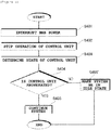
- FIG. 5 is a flowchart for describing a progress process in an application example of applying the system for controlling a relay using a flip-flop illustrated in FIGS. 2 and 3 .
- the control unit which is positioned in the BMS and operated by sharing the power of the BMS also stops the function (S402).
- the clock signal generating unit when the clock signal generating unit does not receive the communication signal from the control unit, the clock signal generating unit continuously determines the state of the control unit by attempting communication to the control unit for a predetermined time (S403).
- the clock signal generating unit is switched to the idle state after a predetermined time elapses, and as a result, the power supplied to the flip-flop is interrupted and the power of the vehicle is interrupted (S405').
Abstract
Description
- This application claims priority to and the benefit of Korean Patent Application No.
10-2018-0115723 - The present invention relates to a system and a method for controlling a relay using a flip-flop, and particularly, to a system and a method for controlling a relay using a flip-flop, which install a flip-flop controlling a relay by receiving a signal of a control unit in a battery management system of a vehicle and supply flip-flop operation power to the flip-flop through a monitoring circuit connected to a battery of the vehicle even when an operation power of the battery management system of the vehicle is interrupted to maintain a closing state of a relay controlling driving power of the vehicle and conserve power of the vehicle for a predetermined time.
- A secondary battery which is high in application easiness according to a product group and has electrical characteristics including high energy density, and the like is universally applied to an electric vehicle (EV) driven by an electric driving source, a hybrid vehicle (HV) or an energy storage system (ESS) or an uninterruptible power supply (UPS) system using a medium/large battery used for a house or an industry as well as a portable device.
- Future trends of an automotive industry using the secondary battery may be greatly concentrated on two types of an electric vehicle related to an eco-friendly issue and an autonomous vehicle maximizing convenience of a driver.
- One of most important issues in two vehicles using the secondary battery may be an issue related to stability and there is a problem in that the power of the vehicle may also be immediately interrupted when a situation in which power supplied to a battery management system (BMS) controlling a battery of the vehicle is unexpectedly interrupted during driving occurs. In order to cope with a problem which occurs in such an emergency situation, a function may be required in which the power of the vehicle is not immediately interrupted, but maintained for a predetermined time at the time of interrupting a battery management system operation power to cope with the emergency situation.
- The present invention is contrived to solve the problem and has been made in an effort to transfer a system and a method for controlling a relay using a flip-flop which install a flip-flop capable of controlling a relay by receiving a signal of a control unit in a battery management system of a vehicle and supply flip-flop operation power to the flip-flop through a monitoring circuit connected to a battery of the vehicle even when an operation power of the battery management system of the vehicle is unexpectedly interrupted to maintain a closing state of a relay controlling driving power of the vehicle and conserve power of the vehicle for a predetermined time, thereby coping with an emergency situation.
- According to an embodiment of the present invention, a system for controlling a relay using a flip-flop may include: a control unit generating an input signal for outputting a relay control signal; a clock signal generating unit transmitting and receiving a communication signal to and from the control unit and generating a clock signal for outputting the relay control signal; a flip-flop receiving the clock signal and the input signal and outputting the relay control signal based on the received clock signal and input signal; and a relay receiving the relay control signal and transiting an operation state based on the received relay control signal.
- In an embodiment, the system may further include: an isolator positioned over a boundary between the high-voltage region and the low-voltage region of the BMS and preventing power collision between the high-voltage region and the low-voltage region; a transformer positioned over a boundary between the high-voltage region and the low-voltage region of the BMS and transferring the communication signal generated by the clock signal generating unit and transferred at the high-voltage region side to the low-voltage region and transferring the communication signal generated by the control unit and transferred at the low-voltage region side to the high-voltage region; and a signal converting unit positioned on a communication connection path of the control unit and the clock signal generating unit and converting the communication signal so as to be detected by both the control unit and the clock signal generating unit.
- In an embodiment, the control unit may be positioned in the low-voltage region in the BMS and operated by receiving BMS power for operating the BMS.
- In an embodiment, the clock signal generating unit may be positioned in the high-voltage region in the BMS, operated by receiving battery power of a vehicle, and supply power to the flip-flop.
- In an embodiment, the clock signal generating unit may transfer the clock signal to the flip-flop until the operation state of the relay is transited to a closed state when the input signal generated by the control unit is transferred to the flip-flop and stop generation of the clock signal when it is confirmed that the operation state of the relay is the closed state.
- In an embodiment, the clock signal generating unit may transfer the clock signal to the flip-flop until the operation state of the relay is transited to an opened state when the communication signal for interrupting the power of the battery of the vehicle is transferred from the control unit and stop generation of the clock signal when it is confirmed that the operation state of the relay is the opened state.
- In an embodiment, when the communication signal is not transferred from the control unit while the relay is in the closed state, the clock signal generating unit may maintain power supply to the flip-flop for a predetermined time and interrupt the power supply to the flip-flop when a predetermined time elapses.
- In an embodiment, the flip-flop may include a D flip-flop type logic circuit.
- In an embodiment, the relay may include a semiconductor relay including a metal oxide semiconductor field effect transistor (MOSFET).
- According to another embodiment of the present invention, a method for controlling a relay using a flip-flop may include: generating, by a control unit, an input signal for outputting a relay control signal; transmitting and receiving, by a clock signal generating unit, a communication signal to and from the control unit and generating a clock signal for outputting the relay control signal; receiving, by a flip-flop, the clock signal and the input signal and outputting the relay control signal based on the received clock signal and input signal; and receiving, by a relay, the relay control signal and transiting an operation state based on the received relay control signal.
- In an embodiment, the transmitting and receiving of, by the clock signal generating unit, the communication signal to and from the control unit and generating the clock signal for outputting the relay control signal may include transferring the clock signal to the flip-flop until the operation state of the relay is transited to a closed state when the input signal generated by the control unit is transferred to the flip-flop and stopping generation of the clock signal when it is confirmed that the operation state of the relay is the closed state.
- In an embodiment, the transmitting and receiving of, by the clock signal generating unit, the communication signal to and from the control unit and generating the clock signal for outputting the relay control signal may include transferring the clock signal to the flip-flop until the operation state of the relay is transited to an opened state when the communication signal for interrupting the power of the battery of the vehicle is transferred from the control unit to the clock signal generating unit and stopping generation of the clock signal when it is confirmed that the operation state of the relay is the opened state.
- In an embodiment, the transmitting and receiving of, by the clock signal generating unit, the communication signal to and from the control unit and generating the clock signal for outputting the relay control signal may include when the communication signal is not transferred from the control unit while the relay is in the closed state, maintaining power supply to the flip-flop for a predetermined time and interrupting the power supply to the flip-flop when a predetermined time elapses.
- According to yet another embodiment of the present invention, a battery management system may include: a control unit generating an input signal for outputting a relay control signal; a clock signal generating unit transmitting and receiving a communication signal to and from the control unit and generating a clock signal for outputting the relay control signal; and a flip-flop receiving the clock signal and the input signal and outputting the relay control signal based on the received clock signal and input signal.
- In an embodiment, the battery management system may further include: an isolator positioned over a boundary between the high-voltage region and the low-voltage region of the BMS and preventing power collision between the high-voltage region and the low-voltage region; a transformer positioned over a boundary between the high-voltage region and the low-voltage region of the BMS and transferring the communication signal transferred at the high-voltage region side to the low-voltage region and transferring the communication signal transferred at the low-voltage region side to the high-voltage region; and a signal converting unit positioned on a communication connection path of the control unit and the clock signal generating unit and converting the communication signal so as to be detected by both the control unit and the clock signal generating unit.
- A system and a method for controlling a relay using a flip-flop according to embodiments of the present invention install a flip-flop in a battery management system of a vehicle and supply flip-flop operation power to the flip-flop through a monitoring circuit connected to a battery of the vehicle even when an operation power of the battery management system of the vehicle is unexpectedly interrupted to maintain a closing state of a relay controlling driving power of the vehicle and conserve power of the vehicle for a predetermined time, thereby coping with an emergency situation.
-
-
FIG. 1 is a diagram illustrating a shape of arelay control system 1 in the related art. -
FIG. 2 is a diagram illustrating a configuration of asystem 100 for controlling a relay using a flip-flop according to an embodiment of the present invention. -
FIG. 3 is a diagram more specifically illustrating asystem 100 for controlling a relay using a flip-flop according to an embodiment of the present invention. -
FIG. 4 is a flowchart for describing a relay control process through asystem 100 for controlling a relay using a flip-flop according to an embodiment of the present invention. -
FIG. 5 is a flowchart for describing a progress process of an application example of applying asystem 100 for controlling a relay using a flip-flop according to the present invention. - The present invention will be described below in detail with reference to the accompanying drawings. Herein, the repeated description and the detailed description of publicly-known function and configuration that may make the gist of the present invention unnecessarily ambiguous will be omitted. Embodiments of the present invention are provided for more completely describing the present invention to those skilled in the art. Accordingly, shapes, sizes, and the like of elements in the drawings may be exaggerated for clearer explanation.
- Throughout the specification, unless explicitly described to the contrary, a case where any part "includes" any component will be understood to imply the inclusion of stated components but not the exclusion of any other component.
- In addition, the term "...unit" disclosed in the specification means a unit that processes at least one function or operation, and the unit may be implemented by hardware or software or a combination of hardware and software.
-
FIG. 1 is a diagram illustrating a shape of arelay control system 1 in the related art. - Referring to
FIG. 1 , in therelay control system 1 in the related art, an input signal of acontrol unit 1a is transferred to arelay 1c through anisolator 1d and an operation state of therelay 1c is controlled and a connection state between a vehicle and abattery 10 is changed according to the operation state of therelay 1c. - Here, the
battery 10 may mean a main power supply capable of driving the vehicle and mean a battery cell included in a battery pack mounted on the vehicle. - More specifically, in the
relay control system 1, since whether thebattery 10 is interrupted is determined by controlling the operation state of therelay 1c through the input signal of thecontrol unit 1a, when a function of thecontrol unit 1a is stopped or the power is interrupted, the input signal is not generated, and as a result, therelay 1c deviates from the control and thebattery 10 is interrupted, and as a result, the power of the vehicle is also lost. - The
relay control system 1 has a problem in that when a problem occurs in the BMS of the vehicle which is driven or the power is interrupted, power loss of the vehicle is immediately followed, and as a result, it is difficult to cope with the emergency situation. -
FIG. 2 is a diagram illustrating a configuration of asystem 100 for controlling a relay using a flip-flop according to an embodiment of the present invention andFIG. 3 is a diagram more specifically illustrating asystem 100 for controlling a relay using a flip-flop according to an embodiment of the present invention. - Referring to
FIGS. 2 and3 , thesystem 100 for controlling a relay using a flip-flop according to an embodiment of the present invention may be configured to generally include acontrol unit 101, a clocksignal generating unit 102, a flip-flop 103, and arelay 104. Further, additionally, in an embodiment, thesystem 100 may be configured to further include anisolator 105, atransformer 106, and asignal converting unit 107. Thesystem 100 for controlling a relay using a flip-flop illustrated inFIGS. 2 and3 follows the embodiment and constituent elements thereof are not limited to the embodiment illustrated inFIGS. 2 and3 and as necessary, some constituent elements may be added, modified, or deleted. - First, the
control unit 101 may generate an input signal for outputting a relay control signal. - Further, the
control unit 101 may be positioned in a low-voltage region in the battery management system (BMS) and operated by receiving BMS power for operating the BMS. - Here, an inner part of the BMS may be divided into a high-voltage region and a low-voltage region, and the high-voltage region may mean a region where a circuit and elements which may be directly or indirectly connected to the
battery 10 of the vehicle and may use or handle voltage of approximately several hundred voltage or higher are positioned and the low-voltage region may mean a region where a circuit and elements which may use or handle voltage of approximately 10 volt or lower are positioned. - Next, the clock
signal generating unit 102 may generate a clock signal for transmitting and receiving a communication signal with thecontrol unit 101 and outputting a relay control signal. - Further, the clock
signal generating unit 102 may be positioned in the high-voltage region in the BMS, operated by receiving the power of thebattery 10 of the vehicle, and may supply the power to the flip-flop 103. - Further, the clock
signal generating unit 102 may transfer the clock signal to the flip-flop 103 until the operation state of therelay 104 is transited to the closed state when the input signal generated by thecontrol unit 101 is transferred to the flip-flop 103 and stop generation of the clock signal when it is confirmed that the operation state of therelay 104 is the closed state. - Further, the clock
signal generating unit 102 may transfer the clock signal to the flip-flop 103 until the operation state of therelay 104 is transited to an opened state when the communication signal for interrupting the power of thebattery 10 of the vehicle is transferred from thecontrol unit 101 and may stop generation of the clock signal when it is confirmed that the operation state of therelay 104 is the opened state. - In addition, when the communication signal is not transferred from the
control unit 101 while therelay 104 is in the closed state, the clocksignal generating unit 102 may maintain power supply to the flip-flop 103 for a predetermined time and interrupt the power supply to the flip-flop 103 when a predetermined time elapses. - Here, the predetermined time may be a fixed value preset in the clock
signal generating unit 102 and a value changed through the input of a user into the BMS, and the predetermined time in the embodiment may be 60 seconds. - Specifically, as an example, while the clock
signal generating unit 102 performs bidirectional communication with thecontrol unit 101 in a state in which therelay 104 is in the closed state, if the communication signal is not transferred from thecontrol unit 101, the clocksignal generating unit 102 continuously determines a state of thecontrol unit 101 by attempting communication with thecontrol unit 101 for 60 seconds. During 60 seconds, in order to prevent the power of the vehicle from being lost, the closed state of therelay 104 is maintained by maintaining the power supply to the flip-flop 103 for 60 seconds and even though 60 seconds elapses, if the communication signal is not transferred from thecontrol unit 101, the clocksignal generating unit 102 interrupts the power supply to the flip-flop 103 while being switched to an idle state. - Next, the flip-
flop 103 may receive the clock signal and the input signal and output the relay control signal based on the received clock signal and input signal. - Here, the flip-
flop 103 may include a D flip-flop type logic circuit. - Specifically, for example, when the flip-
flop 103 receives the clock signal transferred from the clocksignal generating unit 102, the flip-flop 103 may output an input value of the input signal transferred from thecontrol unit 101 as the output value as it is. Accordingly, when an input signal for transiting therelay 104 to the closed state or opened state is transferred to the flip-flop 103, thecontrol unit 101 may allow the clocksignal generating unit 102 to continuously output an initial input value as an output value when stopping generation of the clock signal after allowing the flip-flop103 to output the input value and stop generation of the clock signal by transferring a clock signal of approximately one period to the flip-flop 103. - Next, the
relay 104 may receive the relay control signal and transit the operation state based on the received relay control signal. - Here, the
relay 104 may mean a semiconductor relay including a metal oxide semiconductor field effect transistor (MOSFET). - Next, the
isolator 105 may be positioned over a boundary between the high-voltage region and the low-voltage region of the BMS and may prevent power collision between the high-voltage region and the low-voltage region. - Here, the
isolator 105 may transfer the input signal transferred from thecontrol unit 101 in the low-voltage region to the flip-flop 103 of the high-voltage region without a power collision between the high-voltage region and the low-voltage region. - Next, the
transformer 106 may be positioned on a boundary between the high-voltage region and the low-voltage region of the BMS, the communication signal generated by the clocksignal generating unit 102 and transferred from the high-voltage region side is transferred to the low-voltage region and the communication signal generated by thecontrol unit 101 and transferred from the low-voltage region may be transferred to the high-voltage region. - Next, the
signal converting unit 107 may be positioned on a communication connection path of thecontrol unit 101 and the clocksignal generating unit 102 and convert the communication signal to be detected by both thecontrol unit 101 and the clocksignal generating unit 102. - Here, communication made between communication connection paths of the
signal converting unit 107 and thecontrol unit 101 may include Serial Peripheral Interface (SPI) communication. - Next, a relay control process through the
system 100 for controlling a relay using a flip-flop will be described throughFIG. 4 . -
FIG. 4 is a flowchart for describing a relay control process through a relay control system using the flip-flop illustrated inFIGS. 2 and3 . - Referring to
FIG. 4 , first, a control unit generates an input signal for outputting a relay control signal (S301) and transfers the generated input signal to the flip-flop in the high-voltage region through an isolator (S302). - Next, the clock signal generating unit generates the clock signal and transfers the generated clock signal to the flip-flop through the bidirectional communication with the control unit (S303).
- Next, the flip-flop outputs the relay control signal according to a logic circuit of a D flip-flop based on the transferred input signal and clock signal (S304) and the relay receives the relay control signal generated by the flip-flop and determines the operation state to interrupt or connect the battery (S305).
- Next, a progress process of an application example of applying the
system 100 for controlling a relay using a flip-flop will be described with reference toFIG. 5 . -
FIG. 5 is a flowchart for describing a progress process in an application example of applying the system for controlling a relay using a flip-flop illustrated inFIGS. 2 and3 . - Referring to
FIG. 5 , first, when a situation in which the power of the BMS is interrupted occurs due to a problem which is not intended or may not be known by a user occurs in the BMS (S401), the control unit which is positioned in the BMS and operated by sharing the power of the BMS also stops the function (S402). - Next, when the clock signal generating unit does not receive the communication signal from the control unit, the clock signal generating unit continuously determines the state of the control unit by attempting communication to the control unit for a predetermined time (S403).
- Here, when the function of the control unit is recovered within a predetermined time and the communication is resumed again, the clock signal generating unit maintains power supply to the flip-flop, and as a result, the relay control system using the flip-flop is continued (S405).
- Meanwhile, when the function of the control unit is not recovered within the predetermined time and the communication is not resumed, the clock signal generating unit is switched to the idle state after a predetermined time elapses, and as a result, the power supplied to the flip-flop is interrupted and the power of the vehicle is interrupted (S405').
- The aforementioned method for relaying the relay using the flip-flop has been described with reference to the flowcharts presented in the drawings. The method has been shown and described by a series of blocks for easy description, but it is to be understood that the present invention is not limited to the order of the blocks, and that some blocks may be generated in different orders from and concurrently with other blocks as shown and described in the present specification, and various other branches, flow paths, and orders of blocks may be implemented to achieve the same or similar result. In addition, all illustrated blocks may not be required for the implementation of the method described in the present specification.
- The present invention has been described with reference to the preferred embodiments of the present invention, but those skilled in the art will understand that the present invention can be variously modified and changed without departing from the spirit and the scope of the present invention which are defined in the appended claims.
Claims (15)
- A system for controlling a relay using a flip-flop, the system comprising:a control unit generating an input signal for outputting a relay control signal;a clock signal generating unit transmitting and receiving a communication signal to and from the control unit and generating a clock signal for outputting the relay control signal;a flip-flop receiving the clock signal and the input signal and outputting the relay control signal based on the received clock signal and input signal; anda relay receiving the relay control signal and transiting an operation state based on the received relay control signal.
- The system of claim 1, further comprising:an isolator positioned over a boundary between the high-voltage region and the low-voltage region of the BMS and preventing power collision between the high-voltage region and the low-voltage region;a transformer positioned over a boundary between the high-voltage region and the low-voltage region of the BMS and transferring the communication signal generated by the clock signal generating unit and transferred at the high-voltage region side to the low-voltage region and transferring the communication signal generated by the control unit and transferred at the low-voltage region side to the high-voltage region; anda signal converting unit positioned on a communication connection path of the control unit and the clock signal generating unit and converting the communication signal so as to be detected by both the control unit and the clock signal generating unit.
- The system of claim 2, wherein the control unit is positioned in the low-voltage region in the BMS and operated by receiving BMS power for operating the BMS.
- The system of claim 2, wherein the clock signal generating unit is positioned in the high-voltage region in the BMS, operated by receiving battery power of a vehicle, and supplies power to the flip-flop.
- The system of claim 1, wherein the clock signal generating unit transfers the clock signal to the flip-flop until the operation state of the relay is transited to a closed state when the input signal generated by the control unit is transferred to the flip-flop and stops generation of the clock signal when it is confirmed that the operation state of the relay is the closed state.
- The system of claim 4, wherein the clock signal generating unit transfers the clock signal to the flip-flop until the operation state of the relay is transited to an opened state when the communication signal for interrupting the power of the battery of the vehicle is transferred from the control unit and stops generation of the clock signal when it is confirmed that the operation state of the relay is the opened state.
- The system of claim 4, wherein when the communication signal is not transferred from the control unit while the relay is in the closed state, the clock signal generating unit maintains power supply to the flip-flop for a predetermined time and interrupts the power supply to the flip-flop when a predetermined time elapses.
- The system of claim 1, wherein the flip-flop includes a D flip-flop type logic circuit.
- The system of claim 1, wherein the relay is a semiconductor relay including a metal oxide semiconductor field effect transistor (MOSFET).
- A method for controlling a relay using a flip-flop, the method comprising:generating, by a control unit, an input signal for outputting a relay control signal;transmitting and receiving, by a clock signal generating unit, a communication signal to and from the control unit and generating a clock signal for outputting the relay control signal;receiving, by a flip-flop, the clock signal and the input signal and outputting the relay control signal based on the received clock signal and input signal; andreceiving, by a relay, the relay control signal and transiting an operation state based on the received relay control signal.
- The method of claim 10, wherein the transmitting and receiving of, by the clock signal generating unit, the communication signal to and from the control unit and generating the clock signal for outputting the relay control signal includes
transferring, by the clock signal generating unit, the clock signal to the flip-flop until the operation state of the relay is transited to a closed state when the input signal generated by the control unit is transferred to the flip-flop and stopping generation of the clock signal when it is confirmed that the operation state of the relay is the closed state. - The method of claim 10, wherein the transmitting and receiving of, by the clock signal generating unit, the communication signal to and from the control unit and generating the clock signal for outputting the relay control signal includes
transferring, by the clock signal generating unit, the clock signal to the flip-flop until the operation state of the relay is transited to an opened state when the communication signal for interrupting the power of the battery of the vehicle is transferred from the control unit to the clock signal generating unit and stopping generation of the clock signal when it is confirmed that the operation state of the relay is the opened state. - The method of claim 10, wherein the transmitting and receiving of, by the clock signal generating unit, the communication signal to and from the control unit and generating the clock signal for outputting the relay control signal includes
when the communication signal is not transferred from the control unit while the relay is in the closed state, maintaining power supply to the flip-flop for a predetermined time and interrupting the power supply to the flip-flop when a predetermined time elapses. - A battery management system comprising:a control unit generating an input signal for outputting a relay control signal;a clock signal generating unit transmitting and receiving a communication signal to and from the control unit and generating a clock signal for outputting the relay control signal; anda flip-flop receiving the clock signal and the input signal and outputting the relay control signal based on the received clock signal and input signal.
- The battery management system of claim 14, further comprising:an isolator positioned over a boundary between the high-voltage region and the low-voltage region of the BMS and preventing power collision between the high-voltage region and the low-voltage region;a transformer positioned over a boundary between the high-voltage region and the low-voltage region of the BMS and transferring the communication signal transferred at the high-voltage region side to the low-voltage region and transferring the communication signal transferred at the low-voltage region side to the high-voltage region; anda signal converting unit positioned on a communication connection path of the control unit and the clock signal generating unit and converting the communication signal so as to be detected by both the control unit and the clock signal generating unit.
Applications Claiming Priority (2)
| Application Number | Priority Date | Filing Date | Title |
|---|---|---|---|
| KR1020180115723A KR102447096B1 (en) | 2018-09-28 | 2018-09-28 | System and method for controlling relay using flipflop |
| PCT/KR2019/012600 WO2020067773A1 (en) | 2018-09-28 | 2019-09-27 | System and method for controlling relay using flip-flop |
Publications (3)
| Publication Number | Publication Date |
|---|---|
| EP3756936A1 true EP3756936A1 (en) | 2020-12-30 |
| EP3756936A4 EP3756936A4 (en) | 2021-08-11 |
| EP3756936B1 EP3756936B1 (en) | 2024-02-21 |
Family
ID=69950632
Family Applications (1)
| Application Number | Title | Priority Date | Filing Date |
|---|---|---|---|
| EP19864453.6A Active EP3756936B1 (en) | 2018-09-28 | 2019-09-27 | System and method for controlling relay using flip-flop |
Country Status (6)
| Country | Link |
|---|---|
| US (1) | US11590859B2 (en) |
| EP (1) | EP3756936B1 (en) |
| JP (1) | JP7092441B2 (en) |
| KR (1) | KR102447096B1 (en) |
| CN (1) | CN111918787B (en) |
| WO (1) | WO2020067773A1 (en) |
Families Citing this family (4)
| Publication number | Priority date | Publication date | Assignee | Title |
|---|---|---|---|---|
| US11884182B2 (en) * | 2020-03-31 | 2024-01-30 | Samsung Sdi Co., Ltd. | Electric-vehicle battery system including a real time clock |
| KR20210143535A (en) | 2020-05-20 | 2021-11-29 | 주식회사 엘지에너지솔루션 | Apparatus and method for controlling relay |
| KR20220065603A (en) * | 2020-11-13 | 2022-05-20 | 주식회사 엘지에너지솔루션 | Apparatus and method for controlling relay |
| CN116931531B (en) * | 2023-09-15 | 2024-02-06 | 宁德时代新能源科技股份有限公司 | Safety control system and method for battery production line |
Family Cites Families (26)
| Publication number | Priority date | Publication date | Assignee | Title |
|---|---|---|---|---|
| US4491768A (en) * | 1981-11-04 | 1985-01-01 | Eaton Corporation | Pulse width modulation inverter with battery charger |
| JPH06199146A (en) * | 1992-11-12 | 1994-07-19 | Honda Motor Co Ltd | Motor-driven vehicle control device |
| JPH06333480A (en) * | 1993-05-19 | 1994-12-02 | Matsushita Electric Ind Co Ltd | Relay driving device |
| KR970008711A (en) | 1995-07-10 | 1997-02-24 | 조영선 | Dual-structure battery unit to enable vehicle start even when discharged |
| KR100447676B1 (en) | 2002-12-11 | 2004-09-08 | 주식회사 팬택앤큐리텔 | Circuit for preventing handset off and method thereof |
| DE10322870B4 (en) * | 2003-05-21 | 2009-10-01 | Infineon Technologies Ag | Method for operating a switching converter and drive circuit for controlling a switch in a switching converter |
| US20050242778A1 (en) * | 2004-04-30 | 2005-11-03 | Yen-Hsi Lin | Controlling circuit for long-time battery retention |
| JP4245624B2 (en) * | 2006-09-20 | 2009-03-25 | トヨタ自動車株式会社 | Power supply control device and power supply control method for hybrid vehicle |
| JP2008206288A (en) * | 2007-02-20 | 2008-09-04 | Toyota Motor Corp | Apparatus, method, and program for vehicle control |
| CA2717789C (en) | 2007-12-11 | 2018-07-31 | Antonio Trigiani | Battery management system |
| DE102010048985A1 (en) * | 2010-10-20 | 2012-04-26 | Li-Tec Battery Gmbh | Battery management system for power supply system with low voltage range and high voltage range |
| JP5644560B2 (en) | 2011-02-04 | 2014-12-24 | 株式会社オートネットワーク技術研究所 | Vehicle power supply control device |
| KR20120138125A (en) * | 2011-06-14 | 2012-12-24 | 현대모비스 주식회사 | Apparatus monitoring wake-up by vehicle battery and mehtod thereof |
| JP6074586B2 (en) | 2012-08-03 | 2017-02-08 | パナソニックIpマネジメント株式会社 | Backup power supply device and automobile using the same |
| CN203705070U (en) * | 2013-12-05 | 2014-07-09 | 北汽福田汽车股份有限公司 | Temperature-detecting device for power battery pack |
| KR102029777B1 (en) * | 2013-12-12 | 2019-10-08 | 현대자동차주식회사 | Apparatus and method for managing a battery of the vehicle |
| KR20160086097A (en) * | 2015-01-09 | 2016-07-19 | 현대모비스 주식회사 | Overcharge prevention circuit and method for enhancing noise tolerance |
| JP6237665B2 (en) | 2015-02-10 | 2017-11-29 | トヨタ自動車株式会社 | Hybrid car |
| KR101684085B1 (en) | 2015-04-06 | 2016-12-07 | 현대자동차주식회사 | Latching relay and high-voltage battery system for hybrid vehicle usging the same |
| WO2017018179A1 (en) | 2015-07-30 | 2017-02-02 | 日立オートモティブシステムズ株式会社 | Electronic control device |
| CN105429202A (en) * | 2015-11-16 | 2016-03-23 | 北京新能源汽车股份有限公司 | Battery management system and control method therefor |
| JP6859739B2 (en) | 2016-02-24 | 2021-04-14 | 三菱マテリアル株式会社 | Thermoelectric conversion cell and thermoelectric conversion module |
| KR20180005008A (en) | 2016-07-05 | 2018-01-15 | 현대자동차주식회사 | Apparatus for preventing overcharge of battery in eco-vehicle |
| KR102121639B1 (en) * | 2016-07-15 | 2020-06-10 | 주식회사 엘지화학 | System and method for perventing the abnormal opening of the contactor using real-time detection |
| US10784800B2 (en) | 2016-12-28 | 2020-09-22 | Hitachi Automotive Systems, Ltd. | Signal control apparatus |
| CN209344264U (en) * | 2019-01-04 | 2019-09-03 | 蜂巢能源科技有限公司 | The contactor holding circuit of battery management system pwm signal control |
-
2018
- 2018-09-28 KR KR1020180115723A patent/KR102447096B1/en active IP Right Grant
-
2019
- 2019-09-27 WO PCT/KR2019/012600 patent/WO2020067773A1/en unknown
- 2019-09-27 JP JP2020551553A patent/JP7092441B2/en active Active
- 2019-09-27 EP EP19864453.6A patent/EP3756936B1/en active Active
- 2019-09-27 CN CN201980023421.7A patent/CN111918787B/en active Active
- 2019-09-27 US US17/041,764 patent/US11590859B2/en active Active
Also Published As
| Publication number | Publication date |
|---|---|
| EP3756936A4 (en) | 2021-08-11 |
| EP3756936B1 (en) | 2024-02-21 |
| JP7092441B2 (en) | 2022-06-28 |
| CN111918787B (en) | 2024-01-12 |
| WO2020067773A1 (en) | 2020-04-02 |
| KR20200036274A (en) | 2020-04-07 |
| US20210086656A1 (en) | 2021-03-25 |
| KR102447096B1 (en) | 2022-09-23 |
| CN111918787A (en) | 2020-11-10 |
| JP2021518098A (en) | 2021-07-29 |
| US11590859B2 (en) | 2023-02-28 |
Similar Documents
| Publication | Publication Date | Title |
|---|---|---|
| EP3756936B1 (en) | System and method for controlling relay using flip-flop | |
| US9884557B2 (en) | Apparatus and method of preventing over-discharge of vehicle battery | |
| EP2476574B1 (en) | Power supply system for vehicle and method of controlling same | |
| CN109941106B (en) | Power supply system for electric vehicle | |
| US9799934B2 (en) | Vehicle electric battery controlling apparatus | |
| US20190263279A1 (en) | On-board control device | |
| JP2020036464A (en) | Vehicular power supply system | |
| CN108482154B (en) | Electric automobile control system | |
| JP6103041B2 (en) | Vehicle power supply | |
| KR20120083066A (en) | Apparatus and method for charging auxiliary power of electric vehicle | |
| CN110192320A (en) | Power supply device and power-supply system | |
| US20150142200A1 (en) | Demand Controller, Charger, and Remote Charging Control System Control Method Using the Same | |
| JP2016086506A (en) | Battery monitoring device and method | |
| KR101551086B1 (en) | Emergency Power supply system using fuelcell | |
| CN109075580A (en) | battery module | |
| KR20140061839A (en) | Apparatus and method for battery charge | |
| US20050242768A1 (en) | Method and apparatus for sharing battery charging resources | |
| JP2017225320A (en) | Power supply system for electric vehicle | |
| JP2009159755A (en) | Motor drive circuit | |
| KR101916792B1 (en) | Control signal processing circuit | |
| EP3088241A1 (en) | Regeneration inverter device for electric railroad | |
| KR101692868B1 (en) | Electric compressor inverter with parallel power and driving method thereof | |
| US9242569B2 (en) | Vehicle charge system and vehicle charge method | |
| JP2020092504A (en) | vehicle | |
| US20220344748A1 (en) | Car power supply system and solid oxide fuel cell vehicle |
Legal Events
| Date | Code | Title | Description |
|---|---|---|---|
| STAA | Information on the status of an ep patent application or granted ep patent |
Free format text: STATUS: THE INTERNATIONAL PUBLICATION HAS BEEN MADE |
|
| PUAI | Public reference made under article 153(3) epc to a published international application that has entered the european phase |
Free format text: ORIGINAL CODE: 0009012 |
|
| STAA | Information on the status of an ep patent application or granted ep patent |
Free format text: STATUS: REQUEST FOR EXAMINATION WAS MADE |
|
| 17P | Request for examination filed |
Effective date: 20200925 |
|
| AK | Designated contracting states |
Kind code of ref document: A1 Designated state(s): AL AT BE BG CH CY CZ DE DK EE ES FI FR GB GR HR HU IE IS IT LI LT LU LV MC MK MT NL NO PL PT RO RS SE SI SK SM TR |
|
| AX | Request for extension of the european patent |
Extension state: BA ME |
|
| A4 | Supplementary search report drawn up and despatched |
Effective date: 20210713 |
|
| RIC1 | Information provided on ipc code assigned before grant |
Ipc: B60L 58/10 20190101AFI20210707BHEP Ipc: B60L 3/00 20190101ALI20210707BHEP Ipc: B60L 53/00 20190101ALI20210707BHEP |
|
| DAV | Request for validation of the european patent (deleted) | ||
| DAX | Request for extension of the european patent (deleted) | ||
| RAP1 | Party data changed (applicant data changed or rights of an application transferred) |
Owner name: LG ENERGY SOLUTION LTD. |
|
| RAP3 | Party data changed (applicant data changed or rights of an application transferred) |
Owner name: LG ENERGY SOLUTION, LTD. |
|
| GRAP | Despatch of communication of intention to grant a patent |
Free format text: ORIGINAL CODE: EPIDOSNIGR1 |
|
| STAA | Information on the status of an ep patent application or granted ep patent |
Free format text: STATUS: GRANT OF PATENT IS INTENDED |
|
| INTG | Intention to grant announced |
Effective date: 20230316 |
|
| GRAS | Grant fee paid |
Free format text: ORIGINAL CODE: EPIDOSNIGR3 |
|
| GRAJ | Information related to disapproval of communication of intention to grant by the applicant or resumption of examination proceedings by the epo deleted |
Free format text: ORIGINAL CODE: EPIDOSDIGR1 |
|
| GRAL | Information related to payment of fee for publishing/printing deleted |
Free format text: ORIGINAL CODE: EPIDOSDIGR3 |
|
| STAA | Information on the status of an ep patent application or granted ep patent |
Free format text: STATUS: REQUEST FOR EXAMINATION WAS MADE |
|
| P01 | Opt-out of the competence of the unified patent court (upc) registered |
Effective date: 20230516 |
|
| INTC | Intention to grant announced (deleted) | ||
| GRAP | Despatch of communication of intention to grant a patent |
Free format text: ORIGINAL CODE: EPIDOSNIGR1 |
|
| STAA | Information on the status of an ep patent application or granted ep patent |
Free format text: STATUS: GRANT OF PATENT IS INTENDED |
|
| INTG | Intention to grant announced |
Effective date: 20231122 |
|
| GRAA | (expected) grant |
Free format text: ORIGINAL CODE: 0009210 |
|
| STAA | Information on the status of an ep patent application or granted ep patent |
Free format text: STATUS: THE PATENT HAS BEEN GRANTED |
|
| AK | Designated contracting states |
Kind code of ref document: B1 Designated state(s): AL AT BE BG CH CY CZ DE DK EE ES FI FR GB GR HR HU IE IS IT LI LT LU LV MC MK MT NL NO PL PT RO RS SE SI SK SM TR |
|
| REG | Reference to a national code |
Ref country code: GB Ref legal event code: FG4D |
|
| REG | Reference to a national code |
Ref country code: CH Ref legal event code: EP |
|
| REG | Reference to a national code |
Ref country code: DE Ref legal event code: R096 Ref document number: 602019047076 Country of ref document: DE |
|
| REG | Reference to a national code |
Ref country code: IE Ref legal event code: FG4D |