EP3756836B1 - Serviceroboter - Google Patents
Serviceroboter Download PDFInfo
- Publication number
- EP3756836B1 EP3756836B1 EP20162876.5A EP20162876A EP3756836B1 EP 3756836 B1 EP3756836 B1 EP 3756836B1 EP 20162876 A EP20162876 A EP 20162876A EP 3756836 B1 EP3756836 B1 EP 3756836B1
- Authority
- EP
- European Patent Office
- Prior art keywords
- robot
- housing
- groove
- main body
- service
- Prior art date
- Legal status (The legal status is an assumption and is not a legal conclusion. Google has not performed a legal analysis and makes no representation as to the accuracy of the status listed.)
- Active
Links
Images



Classifications
-
- B—PERFORMING OPERATIONS; TRANSPORTING
- B25—HAND TOOLS; PORTABLE POWER-DRIVEN TOOLS; MANIPULATORS
- B25J—MANIPULATORS; CHAMBERS PROVIDED WITH MANIPULATION DEVICES
- B25J19/00—Accessories fitted to manipulators, e.g. for monitoring, for viewing; Safety devices combined with or specially adapted for use in connection with manipulators
- B25J19/0075—Means for protecting the manipulator from its environment or vice versa
-
- B—PERFORMING OPERATIONS; TRANSPORTING
- B25—HAND TOOLS; PORTABLE POWER-DRIVEN TOOLS; MANIPULATORS
- B25J—MANIPULATORS; CHAMBERS PROVIDED WITH MANIPULATION DEVICES
- B25J9/00—Program-controlled manipulators
- B25J9/0003—Home robots, i.e. small robots for domestic use
-
- B—PERFORMING OPERATIONS; TRANSPORTING
- B25—HAND TOOLS; PORTABLE POWER-DRIVEN TOOLS; MANIPULATORS
- B25J—MANIPULATORS; CHAMBERS PROVIDED WITH MANIPULATION DEVICES
- B25J11/00—Manipulators not otherwise provided for
- B25J11/008—Manipulators for service tasks
-
- B—PERFORMING OPERATIONS; TRANSPORTING
- B25—HAND TOOLS; PORTABLE POWER-DRIVEN TOOLS; MANIPULATORS
- B25J—MANIPULATORS; CHAMBERS PROVIDED WITH MANIPULATION DEVICES
- B25J19/00—Accessories fitted to manipulators, e.g. for monitoring, for viewing; Safety devices combined with or specially adapted for use in connection with manipulators
- B25J19/007—Means or methods for designing or fabricating manipulators
-
- B—PERFORMING OPERATIONS; TRANSPORTING
- B25—HAND TOOLS; PORTABLE POWER-DRIVEN TOOLS; MANIPULATORS
- B25J—MANIPULATORS; CHAMBERS PROVIDED WITH MANIPULATION DEVICES
- B25J19/00—Accessories fitted to manipulators, e.g. for monitoring, for viewing; Safety devices combined with or specially adapted for use in connection with manipulators
- B25J19/02—Sensing devices
-
- B—PERFORMING OPERATIONS; TRANSPORTING
- B25—HAND TOOLS; PORTABLE POWER-DRIVEN TOOLS; MANIPULATORS
- B25J—MANIPULATORS; CHAMBERS PROVIDED WITH MANIPULATION DEVICES
- B25J5/00—Manipulators mounted on wheels or on carriages
- B25J5/007—Manipulators mounted on wheels or on carriages mounted on wheels
-
- B—PERFORMING OPERATIONS; TRANSPORTING
- B25—HAND TOOLS; PORTABLE POWER-DRIVEN TOOLS; MANIPULATORS
- B25J—MANIPULATORS; CHAMBERS PROVIDED WITH MANIPULATION DEVICES
- B25J9/00—Program-controlled manipulators
- B25J9/0009—Constructional details, e.g. manipulator supports, bases
-
- G—PHYSICS
- G05—CONTROLLING; REGULATING
- G05D—SYSTEMS FOR CONTROLLING OR REGULATING NON-ELECTRIC VARIABLES
- G05D1/00—Control of position, course, altitude or attitude of land, water, air or space vehicles, e.g. using automatic pilots
- G05D1/02—Control of position or course in two dimensions
- G05D1/021—Control of position or course in two dimensions specially adapted to land vehicles
- G05D1/0231—Control of position or course in two dimensions specially adapted to land vehicles using optical position detecting means
- G05D1/0238—Control of position or course in two dimensions specially adapted to land vehicles using optical position detecting means using obstacle or wall sensors
- G05D1/024—Control of position or course in two dimensions specially adapted to land vehicles using optical position detecting means using obstacle or wall sensors in combination with a laser
Definitions
- the present disclosure relates to a technical field of robots, and more particularly to a service robot.
- US 10 070 763 B2 discloses a coverage robot including a chassis, multiple drive wheel assemblies disposed on the chassis, and a cleaning assembly carried by the chassis.
- Each drive wheel assembly including a drive wheel assembly housing, a wheel rotatably coupled to the housing, and a wheel drive motor carried by the drive wheel assembly housing and operable to drive the wheel.
- the cleaning assembly including a cleaning assembly housing, a cleaning head rotatably coupled to the cleaning assembly housing, and a cleaning drive motor carried by cleaning assembly housing and operable to drive the cleaning head.
- the wheel assemblies and the cleaning assembly are each separately and independently removable from respective receptacles of the chassis as complete units.
- WO 2017/120180 A1 discloses a character skin for a toy robot has an outer cover having an inner surface that is shaped to conform to an outer surface of a robot body housing of a selfpropelled, toy robot.
- the outer cover can be fitted onto the robot body housing to cover an outer surface thereof and then removed from the housing, preferably with requiring a tool.
- the outer cover has an identification mechanism that provides an identification of a robot character software program, wherein the identification is electronically detected by the toy robot and in response the robot character software program is executed by the toy robot which changes behavior of the toy robot, whenever the outer cover is fitted onto the robot body housing.
- Other embodiments are also described and claimed.
- CN 108 972 590 A discloses a robot head structure and a robot.
- the robot head structure comprises a shell and an image display assembly, and the image display assembly comprises a projector, a reflector and a display screen.
- the projector is arranged inside the shell and electrically connected to a controller, a vivid and rich man-machine interaction image can be displayed on the projector, the singleness of image display is avoided, and the experience of the expression interaction function is enhanced;
- the reflector is arranged inside the shell and is matched with the projector in an included angle, and is used for reflecting the image on the projector,
- the display screen is arranged on the outer surface of the shell and is matched with the shape of the shell, the display screen is matched with the reflector in an included angle, and the display screen is used for displaying the image reflected by the reflector; and the image on the projector is reflected to the display screen through the reflector, a user observes the image through the display screen, the display screen is matched with the shape of the
- the robot terminal comprises a mobile chassis, a robot body, a robot head and a robot control device;
- the robot control device comprises a communication module, a local server, a human-computer interaction module and a main control unit; personal information and interactive records of a user are stored in the local server; in addition, the main control unit can generate matching information of the user according to the personal information and the interactive records;
- the communication module acquires multimedia data from a cloud server side according to the data downloading request and can screen the multimedia data according to the matching information, and therefore multimedia data matched with the attribute and interests of the user can be obtained. Therefore, the intelligent education service robot system and the robot terminal thereof have the advantage of being high in pertinency.
- the present disclosure intends to solve at least one of the above technical problems in related art to a certain extent. Therefore, the present disclosure proposes a service robot, which blocks fasteners exposed outside a robot housing by means of a shielding structure, so as to effectively improve the aesthetics and integrity of the overall appearance of the service robot.
- the service robot includes: a service robot, including: a robot housing, the robot main body being arranged in the robot housing, and the robot housing being configured to be fixed on the robot main body by means of a fastener; a shielding structure being configured to be fit on the robot housing to block the fastener.
- the shielding structure includes a second shielding member.
- the robot housing has a display through-hole, and the service robot also has a front display that faces directly the display through-hole.
- An inner wall of the display through-hole is connected with a fixed edge extending to the inside of the robot housing.
- the fixed edge is configured to be fastened with the robot main body by means of the fastener, and the second shielding member is configured to be fitted with the display through-hole to shield the fixed edge and the fastener.
- the service robot shields the fastener exposed outside the robot housing by means of the shielding structure, thereby effectively improving the aesthetics and integrity of the overall appearance of the service robot.
- the service robot according to embodiments of the present disclosure can have the additional technical features as follows.
- the shielding structure includes: a first shielding member.
- the robot housing has a groove recessed inwardly, and the fastener is configured to pass through the groove to be fastened with the robot main body.
- the first shielding member is configured to be fitted with the groove to shield the fastener in the groove.
- the first shielding member is configured to be fixed in the groove by snap-fitting.
- an outer surface of the first shielding member is flush with an outer surface of the robot main body.
- the groove is configured as a long groove and allows a plurality of fasteners to pass and be fastened at the same time
- the first shielding member has a long strip structure
- the first shielding member of the long strip structure is closely fitted with the long groove to shield the fasteners in the long groove.
- the robot housing includes a front housing and a rear housing, one of the front housing and the rear housing has a snap, while the other one thereof has a snap slot, and when the snap is fitted in the snap slot, the front housing and the rear housing are fixed together.
- each of the front housing and the rear housing is provided with the groove recessed inwardly.
- the rear housing includes a rear upper housing and a rear lower housing, the groove of the rear housing is formed in the rear lower housing, and the fastener is configured to pass through the groove to be fastened with a base of the robot main body.
- the second shielding member is configured to be snap-fitted with the display through-hole.
- the color of the shielding structure and the color of the robot housing are the same, and the shielding structure is a flexible structure.
- an inner wall surface of at least one of the front housing and the rear housing is provided with fastening studs with internal threads, a plurality of fastening plates extend from the robot main body, and the fastening studs and the fastening plates are configured to be fastened together by means of fastening bolts.
- the robot main body includes a robot skeleton, a motion mechanism, a control mechanism and a drive mechanism.
- the motion mechanism is arranged below the robot skeleton, and the drive mechanism and the control mechanism are arranged on the robot skeleton.
- the control mechanism is configured to control the drive mechanism to drive the motion mechanism to move.
- the robot housing is provided with a SLAM sensor, an obstacle avoidance sensor and a vision sensor.
- the robot main body includes a robot head driving portion and a robot arm driving portion.
- the robot head driving portion is arranged on top of the robot skeleton, and the robot arm driving portion is arranged on both sides of the robot skeleton.
- a robot head is configured to pass through the robot housing so as to be connected with the robot head driving portion, and a robot arm is configured to pass through the robot housing so as to be connected with the robot arm driving portion.
- first and second are used herein for purposes of description and are not intended to indicate or imply relative importance or significance or to imply the number of indicated technical features.
- the feature defined with “first” and “second” may comprise one or more of this feature.
- the term “a plurality of” means at least two, such as two, three and so on, unless specified otherwise.
- fixed connections, detachable connections, or integral connections may also be mechanical or electrical connections or communication connections; may also be direct connections or indirect connections via intervening structures; may also be inner communications or interactions of two elements, which may be understood by those skilled in the related art according to specific situations.
- a structure in which a first feature is "on" or “below” a second feature may include an embodiment in which the first feature is in direct contact with the second feature, and may also include an embodiment in which the first feature and the second feature are not in direct contact with each other, but are contacted via an additional feature formed therebetween.
- a first feature "on,” “above,” or “on top of' a second feature may include an embodiment in which the first feature is right or obliquely “on,” “above,” or “on top of” the second feature, or just means that the first feature is at a height higher than that of the second feature; while a first feature “below,” “under,” or “on bottom of” a second feature may include an embodiment in which the first feature is right or obliquely “below,” “under,” or “on bottom of” the second feature, or just means that the first feature is at a height lower than that of the second feature.
- a service robot 100 according to an embodiment of the present disclosure will be described below with reference to Figs. 1-4 .
- the service robot 100 may include a robot main body 1, a robot housing 2 and a shielding structure 3.
- the robot main body 1 is arranged in the robot housing 2, and the robot housing 2 is used to protect the robot main body 1 and improve an overall aesthetic appearance of the service robot 100.
- the robot housing 2 is configured to be fixed on the robot main body 1 by means of a fastener, so as to stably arrange the robot housing 2 on the robot main body 1, thereby ensuring the overall stability of the service robot 100.
- the fastener may be a fastening bolt, which is more convenient to fasten and mount.
- the shielding structure 3 is configured to be fit on the robot housing 2 to block the fastener. As the fastener is blocked by the shielding structure 3 arranged on the robot housing 2, the exposed fastener will not be observed by external people, and the aesthetics and integrity of the overall appearance of the service robot 100 will be improved effectively.
- the service robot 100 blocks the fastener exposed outside the robot housing 2 by means of the shielding structure 3, so as to effectively improve the aesthetics and integrity of the overall appearance of the service robot 100.
- the shielding structure 3 includes: a first shielding member 31.
- the robot housing 2 includes: a front housing 24 and a rear housing 25.
- the front housing 24 and the rear housing 25 are engaged, and assembled in the form of snap-fit fixation to form a complete robot housing 2.
- one of the front housing 24 and the rear housing 25 has a snap, while the other one thereof has a snap slot fitted with the snap.
- the front housing 24 and the rear housing 25 are stably fixed together.
- the number of fasteners used additionally to the service robot 100 may be effectively decreased, thereby further effectively reducing the overall weight of the service robot 100 and ensuring the aesthetics and integrity of the overall appearance of the service robot 100.
- Both of the front housing 24 and the rear housing 25 are provided with grooves 21 recessed inwardly to the inside of the robot housing 2 (towards the robot main body 1), and the rear housing 25 also includes: a rear upper housing 251 and a rear lower housing 252.
- the groove 21 of the rear housing 25 is formed on the rear lower housing 252, and the fastener is configured to pass through the groove 21 to be fastened with a base of the robot main body 1.
- the fastener is exemplified as a fastening bolt
- a rod portion of the fastening bolt will pass through a bottom wall of the groove 21 and be fastened with the base of the robot main body 1, while a head portion of the fastening bolt will stay in the groove 21 to be exposed outside the robot housing 2.
- the first shielding member 31 is configured to cooperate with the groove 21 to shield the fastener (the head portion of the fastening bolt) in the groove 21, such that external people cannot observe the exposed fastener from outside, thereby effectively improving the aesthetics and integrity of the overall appearance of the service robot 100.
- the first shielding member 31 may be of a long strip structure (refer to Fig. 2 and Fig. 4 ), and the groove 21 may be a long groove 21, such that the groove 21 can allow a plurality of fasteners to pass and be fastened at the same time.
- the first shielding member 31 in the long strip shape may also be closely fitted with the long groove 21 to shield the fasteners in the long groove 21.
- the first shielding member 31 is configured to be snap-fitted in the groove 21.
- the mounting becomes convenient, and no separate fastener needs to be provided to fasten the first shielding member 31 and the groove 21, which may effectively save the mounting time.
- the robot housing 2 will not appear uneven due to the mounting of the first shielding member 31 on the robot housing 2, which may further improve the aesthetics and integrity of the overall appearance of the robot housing 2.
- the shielding structure 3 includes a second shielding member 32.
- the robot housing 2 has a display through-hole 22.
- the service robot 100 also has a front display 4, and the front display 4 faces directly the display through-hole 22, such that external person may observe the front display 4 by means of the display through-hole 22.
- An inner wall of the display through-hole 22 is connected with a fixed edge 23 extending to the inside of the robot housing 2.
- the fixed edge 23 is configured to be fastened with the robot main body 1 by means of the fastener, so as to allow the robot housing 2 to be fastened to the robot main body 1.
- the second shielding member 32 is configured to cooperate with the display through-hole 22 to shield the fixed edge 23 and the fastener, such that external people cannot observe the fastener, thereby effectively improving the aesthetics and integrity of the overall appearance of the service robot 100.
- the second shielding member 32 may be of an annular structure (refer to Figs. 2 and 4 ).
- the second shielding member 32 may be fitted with the display through-hole 22 better and more compactly, and the front display 4 may be revealed from a through-hole in the second shielding member 32 to avoid shielding the front display 4.
- the second shielding member 32 is configured to be snap-fitted with the display through-hole 22.
- the mounting becomes convenient, and it is not necessary to arrange a separate fastener to fasten the second shielding member 32 and the display through-hole 22, which may effectively save the mounting time.
- the color of the shielding structure 3 is the same as that of the robot housing 2.
- the appearance color of the robot housing 2 mounted with the shielding structure 3 can keep consistent, and will not appear abrupt, thereby further effectively improving the aesthetics and integrity of the overall appearance of the robot housing 2.
- the shielding structure 3 is a flexible structure, which is more convenient to mount. Compared with a rigid structure, the flexible structure can be fit on the robot housing 2 better and more closely to ensure the integrity of the robot housing 2.
- an inner wall surface of at least one of the front housing 24 and the rear housing 25 is provided with fastening studs 26 with internal threads.
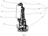
- a plurality of fastening plates 13 configured to be connected with the fastening studs 26 extend from the robot main body 1, and the fastening plates 13 and the fastening studs 26 are configured to be fastened together by means of fastening bolts. That is, the fastening bolt is configured to pass through the fastening plate 13 to be threadedly fastened and connected with the fastening stud 26.
- the fastening stud 26 is of a blind-hole structure with internal threads. After the fastening stud 26 is threadedly fastened with the fastening bolt, the fastening bolt will not penetrate the robot housing 2 to the outside and hence will not be observed by external people, thus realizing a function of concealing the fastener. As a result, not only the fastening of the robot main body 1 and the robot housing 2 can be realized, but also the fastener can be concealed to avoid diminish the aesthetics and integrity of the overall appearance of the service robot 100.
- the fastening studs 26 can be reasonably distributed on the inner wall of the front housing 24 and/or the rear housing 25 according to the specific structure of the robot main body 1, so as to effectively improve the connection stability of the robot main body 1 and the robot housing 2.
- the robot main body 1 includes: a robot skeleton 11, a motion mechanism 12, a control mechanism and a drive mechanism.
- the motion mechanism 12 is arranged below the robot skeleton 11 to facilitate contact with the ground so as to realize the overall motion of the service robot 100.
- the drive mechanism and the control mechanism are arranged on the robot skeleton 11, and the robot skeleton 11 is used to support the drive mechanism and the control mechanism.
- the control mechanism may be a controller, and the drive mechanism may be a drive motor.
- the control mechanism is configured to control the drive mechanism to drive the motion mechanism 12 to move, such that the service robot 100 can move as a whole.
- the motion mechanism 12 may be a plurality of rollers which facilitates the movement of the service robot 100.
- the robot housing 2 is provided with a SLAM (simultaneous localization and mapping) sensor, an obstacle avoidance sensor and a vision sensor.
- the SLAM sensor is used for real-time positioning and map building.
- the obstacle avoidance sensor and the vision sensor are used to enable the service robot 100 to avoid obstacles successfully.
- the above three sensors will transfer the detected information to the control mechanism, and the control mechanism can make a reasonable judgment on road condition information after receiving the signals, and then control the drive mechanism to drive the motion mechanism 12 to move reasonably, thereby achieving the obstacle avoidance movement of the service robot 100 successfully.
- the robot main body 1 includes: a robot head driving portion 15 and a robot arm driving portion 16.
- the robot head driving portion 15 and the robot arm driving portion 16 may be drive motors respectively.
- the robot head driving portion 15 can drive a robot head 5 to rotate, and the robot arm driving portion 16 can drive a robot arm 6 to move and swing.
- the robot head driving portion 15 is arranged on top of the robot skeleton 11 to facilitate the connection with the robot head 5, while the robot arm driving portion 16 is arranged on both sides of the robot skeleton 11 to facilitate the connection with the robot arms 6.
- the robot head 5 is configured to pass through the robot housing 2 so as to be connected with the robot head driving portion
- the robot arm 6 is configured to pass through the robot housing 2 so as to be connected with the robot arm driving portion 16, thereby realizing the assembling of the service robot 100.
Landscapes
- Engineering & Computer Science (AREA)
- Robotics (AREA)
- Mechanical Engineering (AREA)
- Physics & Mathematics (AREA)
- Optics & Photonics (AREA)
- Electromagnetism (AREA)
- Aviation & Aerospace Engineering (AREA)
- Radar, Positioning & Navigation (AREA)
- Remote Sensing (AREA)
- General Physics & Mathematics (AREA)
- Automation & Control Theory (AREA)
- Manipulator (AREA)
- Toys (AREA)
Claims (14)
- Ein Serviceroboter (100), umfassend:einen Roboterhauptkörper (1);ein Robotergehäuse (2), wobei der Roboterhauptkörper (1) in dem Robotergehäuse (2) angeordnet ist und das Robotergehäuse (2) zur Befestigung an dem Roboterhauptkörper (1) mittels eines Befestigungsmittels ausgebildet ist; undeine Abschirmstruktur (3), die so konfiguriert ist, dass sie auf dem Robotergehäuse (2) angebracht werden kann, um das Befestigungselement zu blockieren,dadurch gekennzeichnet, dass die Abschirmstruktur (3) ein zweites Abschirmelement (32) umfasst, das Robotergehäuse (2) eine Display-Durchgangsbohrung (22) aufweist, der Serviceroboter ferner ein Frontdisplay (4) aufweist, das Frontdisplay (4) direkt der Display-Durchgangsbohrung (22) zugewandt ist, eine Innenwand der Display-Durchgangsbohrung (22) mit einer festen Kante (23) verbunden ist, die sich zur Innenseite des Robotergehäuses (2) erstreckt, die feste Kante (23) so konfiguriert ist, dass sie mit dem Roboterhauptkörper (1) mittels des Befestigungselements befestigt wird, und das zweite Abschirmelement (32) so konfiguriert ist, dass es mit der Display-Durchgangsbohrung (22) zusammengefügt wird, um die feste Kante (23) und das Befestigungselement abzuschirmen.
- Serviceroboter (100) nach Anspruch 1, wobei die Abschirmstruktur (3) ein erstes Abschirmelement (31) umfasst, das Robotergehäuse (2) eine nach innen vertiefte Nut (21) aufweist, das Befestigungselement so konfiguriert ist, dass es durch die Nut (21) hindurchgeht, um an dem Roboterhauptkörper (1) befestigt zu werden, und das erste Abschirmelement (31) so konfiguriert ist, dass es in die Nut (21) eingepasst wird, um das Befestigungselement in der Nut (21) abzuschirmen.
- Serviceroboter (100) nach Anspruch 2, wobei das erste Abschirmelement (31) so konfiguriert ist, dass es durch Einrasten in der Nut (21) befestigt wird.
- Serviceroboter (100) nach Anspruch 2 oder 3, wobei nach dem Einsetzen des ersten Abschirmelements (31) in die Nut (21) eine Außenfläche des ersten Abschirmelements (31) mit einer Außenfläche des Roboterhauptkörpers (1) bündig ist.
- Serviceroboter (100) nach einem der Ansprüche 2 bis 4, wobei die Nut (21) als Langnut ausgebildet ist und es mehreren Befestigungselementen ermöglicht, gleichzeitig hindurchzugehen und befestigt zu werden, das erste Abschirmelement (31) eine lange Streifenstruktur aufweist und das erste Abschirmelement (31) der langen Streifenstruktur eng in die Langnut eingepasst ist, um die Befestigungselemente in der Langnut abzuschirmen.
- Serviceroboter (100) nach einem der Ansprüche 2 bis 5, wobei das Robotergehäuse (2) ein vorderes Gehäuse (24) und ein hinteres Gehäuse (25) umfasst, eines von dem vorderen Gehäuse (24) und dem hinteren Gehäuse (25) einen Schnappverschluss aufweist, während das andere davon einen Schnappschlitz aufweist, und wenn der Schnappverschluss in den Schnappschlitz eingepasst ist, sind das vordere Gehäuse (24) und das hintere Gehäuse (25) miteinander befestigt.
- Serviceroboter (100) nach Anspruch 6, wobei sowohl das vordere Gehäuse (24) als auch das hintere Gehäuse (25) mit einer nach innen versetzten Nut (21) versehen ist.
- Serviceroboter (100) nach Anspruch 7, wobei das hintere Gehäuse (25) ein hinteres oberes Gehäuse (251) und ein hinteres unteres Gehäuse (252) umfasst, die Nut (21) des hinteren Gehäuses (25) in dem hinteren unteren Gehäuse (252) ausgebildet ist und das Befestigungselement so konfiguriert ist, dass es durch die Nut (21) hindurchgeht, um an einer Basis des Roboterhauptkörpers (1) befestigt zu werden.
- Serviceroboter (100) nach Anspruch 1, wobei das zweite Abschirmelement (32) so konfiguriert ist, dass es in dem Display-Durchgangsloch (22) einrastet.
- Serviceroboter (100) nach einem der Ansprüche 1 bis 9, wobei die Abschirmstruktur (3) die gleiche Farbe wie das Robotergehäuse (2) hat und die Abschirmstruktur (3) eine flexible Struktur ist.
- Serviceroboter (100) nach einem der Ansprüche 6 bis 8, wobei eine Innenwandfläche des vorderen Gehäuses (24) und/oder des hinteren Gehäuses (25) mit Befestigungsbolzen (26) mit Innengewinde versehen ist, sich mehrere Befestigungsplatten (13) vom Roboterhauptkörper (1) erstrecken und die Befestigungsbolzen (26) und die Befestigungsplatten (13) dazu ausgebildet sind, mittels Befestigungsbolzen miteinander befestigt zu werden.
- Serviceroboter (100) nach einem der Ansprüche 1 bis 11, wobei der Roboterhauptkörper (1) ein Roboterskelett (11), einen Bewegungsmechanismus (12), einen Steuermechanismus und einen Antriebsmechanismus umfasst, der Bewegungsmechanismus (12) unterhalb des Roboterskeletts (11) angeordnet ist, der Antriebsmechanismus und der Steuermechanismus auf dem Roboterskelett (11) angeordnet sind und der Steuermechanismus so konfiguriert ist, dass er den Antriebsmechanismus steuert, um den Bewegungsmechanismus (12) zu bewegen.
- Serviceroboter (100) nach einem der Ansprüche 1 bis 12, wobei das Robotergehäuse (2) mit einem SLAM-Sensor, einem Hindernisvermeidungssensor und einem Vision-Sensor versehen ist.
- Serviceroboter (100) nach einem der Ansprüche 1 bis 13, wobei der Roboterhauptkörper (1) einen Roboterkopf-Antriebsabschnitt (15) und einen Roboterarm-Antriebsabschnitt (16) umfasst, wobei der Roboterkopf-Antriebsabschnitt (15) oben auf dem Roboterskelett (11) angeordnet ist, wobei der Roboterarm-Antriebsabschnitt (16) auf beiden Seiten des Roboterskeletts (11) angeordnet ist, ein Roboterkopf (5) so gestaltet ist, dass er durch das Robotergehäuse (2) hindurchgeht, um mit dem Roboterkopf-Antriebsabschnitt (15) verbunden zu werden, und ein Roboterarm (6) so gestaltet ist, dass er durch das Robotergehäuse (2) hindurchgeht, um mit dem Roboterarm-Antriebsabschnitt (16) verbunden zu werden.
Applications Claiming Priority (2)
| Application Number | Priority Date | Filing Date | Title |
|---|---|---|---|
| CN201921005888.2U CN210589300U (zh) | 2019-06-28 | 2019-06-28 | 服务机器人 |
| CN201910580062.7A CN112140120B (zh) | 2019-06-28 | 2019-06-28 | 服务机器人 |
Publications (2)
| Publication Number | Publication Date |
|---|---|
| EP3756836A1 EP3756836A1 (de) | 2020-12-30 |
| EP3756836B1 true EP3756836B1 (de) | 2024-10-23 |
Family
ID=70227753
Family Applications (1)
| Application Number | Title | Priority Date | Filing Date |
|---|---|---|---|
| EP20162876.5A Active EP3756836B1 (de) | 2019-06-28 | 2020-03-13 | Serviceroboter |
Country Status (2)
| Country | Link |
|---|---|
| US (1) | US11305417B2 (de) |
| EP (1) | EP3756836B1 (de) |
Families Citing this family (6)
| Publication number | Priority date | Publication date | Assignee | Title |
|---|---|---|---|---|
| JP1662890S (de) * | 2019-10-18 | 2020-07-06 | ||
| JP1654992S (de) * | 2019-10-18 | 2020-03-16 | ||
| JP7343366B2 (ja) * | 2019-11-20 | 2023-09-12 | ファナック株式会社 | ロボット用ケーシングおよびロボット |
| USD925637S1 (en) * | 2020-04-17 | 2021-07-20 | Soichiro Nakamura | Autonomous mobile robot |
| USD920411S1 (en) * | 2020-05-29 | 2021-05-25 | Ubtech Robotics Corp Ltd | Robot |
| USD1028047S1 (en) * | 2021-11-24 | 2024-05-21 | Zhenwu Huang | Service robot |
Family Cites Families (14)
| Publication number | Priority date | Publication date | Assignee | Title |
|---|---|---|---|---|
| EP2829939B1 (de) | 2005-12-02 | 2019-11-13 | iRobot Corporation | Roboternavigationssystem mit autonomer Abdeckung |
| US8095238B2 (en) * | 2006-11-29 | 2012-01-10 | Irobot Corporation | Robot development platform |
| GB2494447B (en) * | 2011-09-09 | 2014-02-26 | Dyson Technology Ltd | Autonomous surface treating appliance |
| GB2494444B (en) * | 2011-09-09 | 2013-12-25 | Dyson Technology Ltd | Drive arrangement for a mobile robot |
| JP6240956B2 (ja) | 2013-11-05 | 2017-12-06 | 株式会社デンソーウェーブ | ロボットのカバー取付構造、及びロボット |
| US9193402B2 (en) * | 2013-11-26 | 2015-11-24 | Elwha Llc | Structural assessment, maintenance, and repair apparatuses and methods |
| EP3097755A4 (de) * | 2014-01-21 | 2017-09-13 | Positec Power Tools (Suzhou) Co., Ltd | Automatischer rasenmäher |
| CN111991817A (zh) | 2016-01-06 | 2020-11-27 | 埃沃洛夫有限公司 | 自动玩具机器人 |
| JP6517457B2 (ja) * | 2017-04-10 | 2019-05-22 | Groove X株式会社 | 外皮を装着するロボット |
| CN108000530A (zh) | 2017-12-12 | 2018-05-08 | 湖南超能机器人技术有限公司 | 智能教育服务机器人系统及其机器人终端 |
| KR102168336B1 (ko) * | 2018-07-23 | 2020-10-22 | 엘지전자 주식회사 | 안내 로봇 |
| CN108972590A (zh) | 2018-09-14 | 2018-12-11 | 苏州博众机器人有限公司 | 一种机器人头部结构及机器人 |
| WO2020141631A1 (ko) * | 2019-01-02 | 2020-07-09 | 엘지전자 주식회사 | 이동 로봇 |
| KR102677181B1 (ko) * | 2019-01-02 | 2024-06-20 | 엘지전자 주식회사 | 이동 로봇 |
-
2020
- 2020-03-05 US US16/810,079 patent/US11305417B2/en active Active
- 2020-03-13 EP EP20162876.5A patent/EP3756836B1/de active Active
Also Published As
| Publication number | Publication date |
|---|---|
| US20200406448A1 (en) | 2020-12-31 |
| US11305417B2 (en) | 2022-04-19 |
| EP3756836A1 (de) | 2020-12-30 |
Similar Documents
| Publication | Publication Date | Title |
|---|---|---|
| US11305417B2 (en) | Service robot | |
| CN216759895U (zh) | 自移动机器人 | |
| USD988395S1 (en) | Webcam mount assembly | |
| US20210147056A1 (en) | Flying Robot with Internal Rear Projector | |
| KR20200000721A (ko) | 로봇 | |
| US20100181452A1 (en) | Adjustable display mounting | |
| US20160065803A1 (en) | Television Display Device | |
| US8096428B2 (en) | Counter display for articles such as perfumes and cosmetic products | |
| CN222755459U (zh) | 人形机器人的头颈结构及人形机器人 | |
| CN213339254U (zh) | 编程教育机器人 | |
| CN218368042U (zh) | 一种服务机器人教学移动平台 | |
| JPH0633745Y2 (ja) | 車載用スピーカ取付構造 | |
| CN207617625U (zh) | 一种车用悬浮式显示装置 | |
| CN217659674U (zh) | 清洁机器人 | |
| JPH031622U (de) | ||
| CN220402394U (zh) | 自主作业设备 | |
| CN216454698U (zh) | 一种平板固定结构及应用其的料理机 | |
| CN213025097U (zh) | 信息显示面框角度可调节的房号牌 | |
| CN210495205U (zh) | 一种智能拼装叉车玩具 | |
| JP2519663Y2 (ja) | 間仕切装置における化粧ポスト構造 | |
| JPH0258886U (de) | ||
| CN205871908U (zh) | 具有多功能车载广播系统的汽车 | |
| JPS63138300U (de) | ||
| HK30108682A2 (en) | An automatic displaying and concealing display cabinet | |
| JPH0256265U (de) |
Legal Events
| Date | Code | Title | Description |
|---|---|---|---|
| PUAI | Public reference made under article 153(3) epc to a published international application that has entered the european phase |
Free format text: ORIGINAL CODE: 0009012 |
|
| STAA | Information on the status of an ep patent application or granted ep patent |
Free format text: STATUS: THE APPLICATION HAS BEEN PUBLISHED |
|
| AK | Designated contracting states |
Kind code of ref document: A1 Designated state(s): AL AT BE BG CH CY CZ DE DK EE ES FI FR GB GR HR HU IE IS IT LI LT LU LV MC MK MT NL NO PL PT RO RS SE SI SK SM TR |
|
| AX | Request for extension of the european patent |
Extension state: BA ME |
|
| STAA | Information on the status of an ep patent application or granted ep patent |
Free format text: STATUS: REQUEST FOR EXAMINATION WAS MADE |
|
| 17P | Request for examination filed |
Effective date: 20210625 |
|
| RBV | Designated contracting states (corrected) |
Designated state(s): AL AT BE BG CH CY CZ DE DK EE ES FI FR GB GR HR HU IE IS IT LI LT LU LV MC MK MT NL NO PL PT RO RS SE SI SK SM TR |
|
| GRAP | Despatch of communication of intention to grant a patent |
Free format text: ORIGINAL CODE: EPIDOSNIGR1 |
|
| STAA | Information on the status of an ep patent application or granted ep patent |
Free format text: STATUS: GRANT OF PATENT IS INTENDED |
|
| RIC1 | Information provided on ipc code assigned before grant |
Ipc: B25J 11/00 20060101ALI20240514BHEP Ipc: B25J 19/02 20060101ALI20240514BHEP Ipc: B25J 19/00 20060101AFI20240514BHEP |
|
| INTG | Intention to grant announced |
Effective date: 20240531 |
|
| GRAS | Grant fee paid |
Free format text: ORIGINAL CODE: EPIDOSNIGR3 |
|
| GRAA | (expected) grant |
Free format text: ORIGINAL CODE: 0009210 |
|
| STAA | Information on the status of an ep patent application or granted ep patent |
Free format text: STATUS: THE PATENT HAS BEEN GRANTED |
|
| AK | Designated contracting states |
Kind code of ref document: B1 Designated state(s): AL AT BE BG CH CY CZ DE DK EE ES FI FR GB GR HR HU IE IS IT LI LT LU LV MC MK MT NL NO PL PT RO RS SE SI SK SM TR |
|
| P01 | Opt-out of the competence of the unified patent court (upc) registered |
Free format text: CASE NUMBER: APP_51855/2024 Effective date: 20240916 |
|
| REG | Reference to a national code |
Ref country code: GB Ref legal event code: FG4D |
|
| REG | Reference to a national code |
Ref country code: CH Ref legal event code: EP |
|
| REG | Reference to a national code |
Ref country code: DE Ref legal event code: R096 Ref document number: 602020039776 Country of ref document: DE |
|
| REG | Reference to a national code |
Ref country code: IE Ref legal event code: FG4D |
|
| REG | Reference to a national code |
Ref country code: LT Ref legal event code: MG9D |
|
| REG | Reference to a national code |
Ref country code: NL Ref legal event code: MP Effective date: 20241023 |
|
| REG | Reference to a national code |
Ref country code: AT Ref legal event code: MK05 Ref document number: 1734481 Country of ref document: AT Kind code of ref document: T Effective date: 20241023 |
|
| PG25 | Lapsed in a contracting state [announced via postgrant information from national office to epo] |
Ref country code: NL Free format text: LAPSE BECAUSE OF FAILURE TO SUBMIT A TRANSLATION OF THE DESCRIPTION OR TO PAY THE FEE WITHIN THE PRESCRIBED TIME-LIMIT Effective date: 20241023 |
|
| PG25 | Lapsed in a contracting state [announced via postgrant information from national office to epo] |
Ref country code: NL Free format text: LAPSE BECAUSE OF FAILURE TO SUBMIT A TRANSLATION OF THE DESCRIPTION OR TO PAY THE FEE WITHIN THE PRESCRIBED TIME-LIMIT Effective date: 20241023 |
|
| PG25 | Lapsed in a contracting state [announced via postgrant information from national office to epo] |
Ref country code: HR Free format text: LAPSE BECAUSE OF FAILURE TO SUBMIT A TRANSLATION OF THE DESCRIPTION OR TO PAY THE FEE WITHIN THE PRESCRIBED TIME-LIMIT Effective date: 20241023 Ref country code: PT Free format text: LAPSE BECAUSE OF FAILURE TO SUBMIT A TRANSLATION OF THE DESCRIPTION OR TO PAY THE FEE WITHIN THE PRESCRIBED TIME-LIMIT Effective date: 20250224 Ref country code: IS Free format text: LAPSE BECAUSE OF FAILURE TO SUBMIT A TRANSLATION OF THE DESCRIPTION OR TO PAY THE FEE WITHIN THE PRESCRIBED TIME-LIMIT Effective date: 20250223 |
|
| PG25 | Lapsed in a contracting state [announced via postgrant information from national office to epo] |
Ref country code: FI Free format text: LAPSE BECAUSE OF FAILURE TO SUBMIT A TRANSLATION OF THE DESCRIPTION OR TO PAY THE FEE WITHIN THE PRESCRIBED TIME-LIMIT Effective date: 20241023 |
|
| PG25 | Lapsed in a contracting state [announced via postgrant information from national office to epo] |
Ref country code: BG Free format text: LAPSE BECAUSE OF FAILURE TO SUBMIT A TRANSLATION OF THE DESCRIPTION OR TO PAY THE FEE WITHIN THE PRESCRIBED TIME-LIMIT Effective date: 20241023 |
|
| PG25 | Lapsed in a contracting state [announced via postgrant information from national office to epo] |
Ref country code: ES Free format text: LAPSE BECAUSE OF FAILURE TO SUBMIT A TRANSLATION OF THE DESCRIPTION OR TO PAY THE FEE WITHIN THE PRESCRIBED TIME-LIMIT Effective date: 20241023 |
|
| PG25 | Lapsed in a contracting state [announced via postgrant information from national office to epo] |
Ref country code: NO Free format text: LAPSE BECAUSE OF FAILURE TO SUBMIT A TRANSLATION OF THE DESCRIPTION OR TO PAY THE FEE WITHIN THE PRESCRIBED TIME-LIMIT Effective date: 20250123 |
|
| PG25 | Lapsed in a contracting state [announced via postgrant information from national office to epo] |
Ref country code: AT Free format text: LAPSE BECAUSE OF FAILURE TO SUBMIT A TRANSLATION OF THE DESCRIPTION OR TO PAY THE FEE WITHIN THE PRESCRIBED TIME-LIMIT Effective date: 20241023 Ref country code: GR Free format text: LAPSE BECAUSE OF FAILURE TO SUBMIT A TRANSLATION OF THE DESCRIPTION OR TO PAY THE FEE WITHIN THE PRESCRIBED TIME-LIMIT Effective date: 20250124 Ref country code: LV Free format text: LAPSE BECAUSE OF FAILURE TO SUBMIT A TRANSLATION OF THE DESCRIPTION OR TO PAY THE FEE WITHIN THE PRESCRIBED TIME-LIMIT Effective date: 20241023 |
|
| PG25 | Lapsed in a contracting state [announced via postgrant information from national office to epo] |
Ref country code: PL Free format text: LAPSE BECAUSE OF FAILURE TO SUBMIT A TRANSLATION OF THE DESCRIPTION OR TO PAY THE FEE WITHIN THE PRESCRIBED TIME-LIMIT Effective date: 20241023 |
|
| PG25 | Lapsed in a contracting state [announced via postgrant information from national office to epo] |
Ref country code: RS Free format text: LAPSE BECAUSE OF FAILURE TO SUBMIT A TRANSLATION OF THE DESCRIPTION OR TO PAY THE FEE WITHIN THE PRESCRIBED TIME-LIMIT Effective date: 20250123 |
|
| PG25 | Lapsed in a contracting state [announced via postgrant information from national office to epo] |
Ref country code: SM Free format text: LAPSE BECAUSE OF FAILURE TO SUBMIT A TRANSLATION OF THE DESCRIPTION OR TO PAY THE FEE WITHIN THE PRESCRIBED TIME-LIMIT Effective date: 20241023 |
|
| PG25 | Lapsed in a contracting state [announced via postgrant information from national office to epo] |
Ref country code: DK Free format text: LAPSE BECAUSE OF FAILURE TO SUBMIT A TRANSLATION OF THE DESCRIPTION OR TO PAY THE FEE WITHIN THE PRESCRIBED TIME-LIMIT Effective date: 20241023 |
|
| PG25 | Lapsed in a contracting state [announced via postgrant information from national office to epo] |
Ref country code: EE Free format text: LAPSE BECAUSE OF FAILURE TO SUBMIT A TRANSLATION OF THE DESCRIPTION OR TO PAY THE FEE WITHIN THE PRESCRIBED TIME-LIMIT Effective date: 20241023 |
|
| PG25 | Lapsed in a contracting state [announced via postgrant information from national office to epo] |
Ref country code: RO Free format text: LAPSE BECAUSE OF FAILURE TO SUBMIT A TRANSLATION OF THE DESCRIPTION OR TO PAY THE FEE WITHIN THE PRESCRIBED TIME-LIMIT Effective date: 20241023 |
|
| REG | Reference to a national code |
Ref country code: DE Ref legal event code: R097 Ref document number: 602020039776 Country of ref document: DE |
|
| PG25 | Lapsed in a contracting state [announced via postgrant information from national office to epo] |
Ref country code: SK Free format text: LAPSE BECAUSE OF FAILURE TO SUBMIT A TRANSLATION OF THE DESCRIPTION OR TO PAY THE FEE WITHIN THE PRESCRIBED TIME-LIMIT Effective date: 20241023 |
|
| PG25 | Lapsed in a contracting state [announced via postgrant information from national office to epo] |
Ref country code: CZ Free format text: LAPSE BECAUSE OF FAILURE TO SUBMIT A TRANSLATION OF THE DESCRIPTION OR TO PAY THE FEE WITHIN THE PRESCRIBED TIME-LIMIT Effective date: 20241023 |
|
| PG25 | Lapsed in a contracting state [announced via postgrant information from national office to epo] |
Ref country code: IT Free format text: LAPSE BECAUSE OF FAILURE TO SUBMIT A TRANSLATION OF THE DESCRIPTION OR TO PAY THE FEE WITHIN THE PRESCRIBED TIME-LIMIT Effective date: 20241023 |
|
| PLBE | No opposition filed within time limit |
Free format text: ORIGINAL CODE: 0009261 |
|
| STAA | Information on the status of an ep patent application or granted ep patent |
Free format text: STATUS: NO OPPOSITION FILED WITHIN TIME LIMIT |
|
| PG25 | Lapsed in a contracting state [announced via postgrant information from national office to epo] |
Ref country code: SE Free format text: LAPSE BECAUSE OF FAILURE TO SUBMIT A TRANSLATION OF THE DESCRIPTION OR TO PAY THE FEE WITHIN THE PRESCRIBED TIME-LIMIT Effective date: 20241023 |
|
| 26N | No opposition filed |
Effective date: 20250724 |
|
| PG25 | Lapsed in a contracting state [announced via postgrant information from national office to epo] |
Ref country code: MC Free format text: LAPSE BECAUSE OF FAILURE TO SUBMIT A TRANSLATION OF THE DESCRIPTION OR TO PAY THE FEE WITHIN THE PRESCRIBED TIME-LIMIT Effective date: 20241023 |
|
| REG | Reference to a national code |
Ref country code: CH Ref legal event code: H13 Free format text: ST27 STATUS EVENT CODE: U-0-0-H10-H13 (AS PROVIDED BY THE NATIONAL OFFICE) Effective date: 20251023 |
|
| PG25 | Lapsed in a contracting state [announced via postgrant information from national office to epo] |
Ref country code: LU Free format text: LAPSE BECAUSE OF NON-PAYMENT OF DUE FEES Effective date: 20250313 |
|
| GBPC | Gb: european patent ceased through non-payment of renewal fee |
Effective date: 20250313 |
|
| REG | Reference to a national code |
Ref country code: BE Ref legal event code: MM Effective date: 20250331 |
|
| PG25 | Lapsed in a contracting state [announced via postgrant information from national office to epo] |
Ref country code: GB Free format text: LAPSE BECAUSE OF NON-PAYMENT OF DUE FEES Effective date: 20250313 |
|
| PG25 | Lapsed in a contracting state [announced via postgrant information from national office to epo] |
Ref country code: BE Free format text: LAPSE BECAUSE OF NON-PAYMENT OF DUE FEES Effective date: 20250331 |
|
| PG25 | Lapsed in a contracting state [announced via postgrant information from national office to epo] |
Ref country code: CH Free format text: LAPSE BECAUSE OF NON-PAYMENT OF DUE FEES Effective date: 20250331 |
|
| PG25 | Lapsed in a contracting state [announced via postgrant information from national office to epo] |
Ref country code: IE Free format text: LAPSE BECAUSE OF NON-PAYMENT OF DUE FEES Effective date: 20250313 |
|
| PGFP | Annual fee paid to national office [announced via postgrant information from national office to epo] |
Ref country code: DE Payment date: 20260320 Year of fee payment: 7 |
|
| PGFP | Annual fee paid to national office [announced via postgrant information from national office to epo] |
Ref country code: FR Payment date: 20260209 Year of fee payment: 7 |