EP3756435B1 - Vorrichtung zur einstellung eines hydraulischen oberlenkers - Google Patents
Vorrichtung zur einstellung eines hydraulischen oberlenkers Download PDFInfo
- Publication number
- EP3756435B1 EP3756435B1 EP20401033.4A EP20401033A EP3756435B1 EP 3756435 B1 EP3756435 B1 EP 3756435B1 EP 20401033 A EP20401033 A EP 20401033A EP 3756435 B1 EP3756435 B1 EP 3756435B1
- Authority
- EP
- European Patent Office
- Prior art keywords
- hydraulic
- upper link
- block
- shut
- control
- Prior art date
- Legal status (The legal status is an assumption and is not a legal conclusion. Google has not performed a legal analysis and makes no representation as to the accuracy of the status listed.)
- Active
Links
Images


Classifications
-
- A—HUMAN NECESSITIES
- A01—AGRICULTURE; FORESTRY; ANIMAL HUSBANDRY; HUNTING; TRAPPING; FISHING
- A01B—SOIL WORKING IN AGRICULTURE OR FORESTRY; PARTS, DETAILS, OR ACCESSORIES OF AGRICULTURAL MACHINES OR IMPLEMENTS, IN GENERAL
- A01B59/00—Devices specially adapted for connection between animals or tractors and agricultural machines or implements
- A01B59/002—Details, component parts
- A01B59/004—Length-adjustable links
-
- A—HUMAN NECESSITIES
- A01—AGRICULTURE; FORESTRY; ANIMAL HUSBANDRY; HUNTING; TRAPPING; FISHING
- A01B—SOIL WORKING IN AGRICULTURE OR FORESTRY; PARTS, DETAILS, OR ACCESSORIES OF AGRICULTURAL MACHINES OR IMPLEMENTS, IN GENERAL
- A01B63/00—Lifting or adjusting devices or arrangements for agricultural machines or implements
- A01B63/02—Lifting or adjusting devices or arrangements for agricultural machines or implements for implements mounted on tractors
- A01B63/10—Lifting or adjusting devices or arrangements for agricultural machines or implements for implements mounted on tractors operated by hydraulic or pneumatic means
- A01B63/111—Lifting or adjusting devices or arrangements for agricultural machines or implements for implements mounted on tractors operated by hydraulic or pneumatic means regulating working depth of implements
-
- F—MECHANICAL ENGINEERING; LIGHTING; HEATING; WEAPONS; BLASTING
- F15—FLUID-PRESSURE ACTUATORS; HYDRAULICS OR PNEUMATICS IN GENERAL
- F15B—SYSTEMS ACTING BY MEANS OF FLUIDS IN GENERAL; FLUID-PRESSURE ACTUATORS, e.g. SERVOMOTORS; DETAILS OF FLUID-PRESSURE SYSTEMS, NOT OTHERWISE PROVIDED FOR
- F15B11/00—Servomotor systems without provision for follow-up action; Circuits therefor
- F15B11/003—Systems with load-holding valves
-
- F—MECHANICAL ENGINEERING; LIGHTING; HEATING; WEAPONS; BLASTING
- F15—FLUID-PRESSURE ACTUATORS; HYDRAULICS OR PNEUMATICS IN GENERAL
- F15B—SYSTEMS ACTING BY MEANS OF FLUIDS IN GENERAL; FLUID-PRESSURE ACTUATORS, e.g. SERVOMOTORS; DETAILS OF FLUID-PRESSURE SYSTEMS, NOT OTHERWISE PROVIDED FOR
- F15B2211/00—Circuits for servomotor systems
- F15B2211/30—Directional control
- F15B2211/305—Directional control characterised by the type of valves
- F15B2211/30505—Non-return valves, i.e. check valves
- F15B2211/3051—Cross-check valves
-
- F—MECHANICAL ENGINEERING; LIGHTING; HEATING; WEAPONS; BLASTING
- F15—FLUID-PRESSURE ACTUATORS; HYDRAULICS OR PNEUMATICS IN GENERAL
- F15B—SYSTEMS ACTING BY MEANS OF FLUIDS IN GENERAL; FLUID-PRESSURE ACTUATORS, e.g. SERVOMOTORS; DETAILS OF FLUID-PRESSURE SYSTEMS, NOT OTHERWISE PROVIDED FOR
- F15B2211/00—Circuits for servomotor systems
- F15B2211/30—Directional control
- F15B2211/305—Directional control characterised by the type of valves
- F15B2211/30505—Non-return valves, i.e. check valves
- F15B2211/30515—Load holding valves
-
- F—MECHANICAL ENGINEERING; LIGHTING; HEATING; WEAPONS; BLASTING
- F15—FLUID-PRESSURE ACTUATORS; HYDRAULICS OR PNEUMATICS IN GENERAL
- F15B—SYSTEMS ACTING BY MEANS OF FLUIDS IN GENERAL; FLUID-PRESSURE ACTUATORS, e.g. SERVOMOTORS; DETAILS OF FLUID-PRESSURE SYSTEMS, NOT OTHERWISE PROVIDED FOR
- F15B2211/00—Circuits for servomotor systems
- F15B2211/30—Directional control
- F15B2211/31—Directional control characterised by the positions of the valve element
- F15B2211/3122—Special positions other than the pump port being connected to working ports or the working ports being connected to the return line
- F15B2211/3127—Floating position connecting the working ports and the return line
-
- F—MECHANICAL ENGINEERING; LIGHTING; HEATING; WEAPONS; BLASTING
- F15—FLUID-PRESSURE ACTUATORS; HYDRAULICS OR PNEUMATICS IN GENERAL
- F15B—SYSTEMS ACTING BY MEANS OF FLUIDS IN GENERAL; FLUID-PRESSURE ACTUATORS, e.g. SERVOMOTORS; DETAILS OF FLUID-PRESSURE SYSTEMS, NOT OTHERWISE PROVIDED FOR
- F15B2211/00—Circuits for servomotor systems
- F15B2211/30—Directional control
- F15B2211/31—Directional control characterised by the positions of the valve element
- F15B2211/3138—Directional control characterised by the positions of the valve element the positions being discrete
-
- F—MECHANICAL ENGINEERING; LIGHTING; HEATING; WEAPONS; BLASTING
- F15—FLUID-PRESSURE ACTUATORS; HYDRAULICS OR PNEUMATICS IN GENERAL
- F15B—SYSTEMS ACTING BY MEANS OF FLUIDS IN GENERAL; FLUID-PRESSURE ACTUATORS, e.g. SERVOMOTORS; DETAILS OF FLUID-PRESSURE SYSTEMS, NOT OTHERWISE PROVIDED FOR
- F15B2211/00—Circuits for servomotor systems
- F15B2211/30—Directional control
- F15B2211/32—Directional control characterised by the type of actuation
- F15B2211/327—Directional control characterised by the type of actuation electrically or electronically
-
- F—MECHANICAL ENGINEERING; LIGHTING; HEATING; WEAPONS; BLASTING
- F15—FLUID-PRESSURE ACTUATORS; HYDRAULICS OR PNEUMATICS IN GENERAL
- F15B—SYSTEMS ACTING BY MEANS OF FLUIDS IN GENERAL; FLUID-PRESSURE ACTUATORS, e.g. SERVOMOTORS; DETAILS OF FLUID-PRESSURE SYSTEMS, NOT OTHERWISE PROVIDED FOR
- F15B2211/00—Circuits for servomotor systems
- F15B2211/40—Flow control
- F15B2211/405—Flow control characterised by the type of flow control means or valve
- F15B2211/40576—Assemblies of multiple valves
- F15B2211/40584—Assemblies of multiple valves the flow control means arranged in parallel with a check valve
-
- F—MECHANICAL ENGINEERING; LIGHTING; HEATING; WEAPONS; BLASTING
- F15—FLUID-PRESSURE ACTUATORS; HYDRAULICS OR PNEUMATICS IN GENERAL
- F15B—SYSTEMS ACTING BY MEANS OF FLUIDS IN GENERAL; FLUID-PRESSURE ACTUATORS, e.g. SERVOMOTORS; DETAILS OF FLUID-PRESSURE SYSTEMS, NOT OTHERWISE PROVIDED FOR
- F15B2211/00—Circuits for servomotor systems
- F15B2211/40—Flow control
- F15B2211/41—Flow control characterised by the positions of the valve element
- F15B2211/411—Flow control characterised by the positions of the valve element the positions being discrete
-
- F—MECHANICAL ENGINEERING; LIGHTING; HEATING; WEAPONS; BLASTING
- F15—FLUID-PRESSURE ACTUATORS; HYDRAULICS OR PNEUMATICS IN GENERAL
- F15B—SYSTEMS ACTING BY MEANS OF FLUIDS IN GENERAL; FLUID-PRESSURE ACTUATORS, e.g. SERVOMOTORS; DETAILS OF FLUID-PRESSURE SYSTEMS, NOT OTHERWISE PROVIDED FOR
- F15B2211/00—Circuits for servomotor systems
- F15B2211/40—Flow control
- F15B2211/415—Flow control characterised by the connections of the flow control means in the circuit
- F15B2211/41527—Flow control characterised by the connections of the flow control means in the circuit being connected to an output member and a directional control valve
-
- F—MECHANICAL ENGINEERING; LIGHTING; HEATING; WEAPONS; BLASTING
- F15—FLUID-PRESSURE ACTUATORS; HYDRAULICS OR PNEUMATICS IN GENERAL
- F15B—SYSTEMS ACTING BY MEANS OF FLUIDS IN GENERAL; FLUID-PRESSURE ACTUATORS, e.g. SERVOMOTORS; DETAILS OF FLUID-PRESSURE SYSTEMS, NOT OTHERWISE PROVIDED FOR
- F15B2211/00—Circuits for servomotor systems
- F15B2211/40—Flow control
- F15B2211/42—Flow control characterised by the type of actuation
- F15B2211/426—Flow control characterised by the type of actuation electrically or electronically
-
- F—MECHANICAL ENGINEERING; LIGHTING; HEATING; WEAPONS; BLASTING
- F15—FLUID-PRESSURE ACTUATORS; HYDRAULICS OR PNEUMATICS IN GENERAL
- F15B—SYSTEMS ACTING BY MEANS OF FLUIDS IN GENERAL; FLUID-PRESSURE ACTUATORS, e.g. SERVOMOTORS; DETAILS OF FLUID-PRESSURE SYSTEMS, NOT OTHERWISE PROVIDED FOR
- F15B2211/00—Circuits for servomotor systems
- F15B2211/70—Output members, e.g. hydraulic motors or cylinders or control therefor
- F15B2211/705—Output members, e.g. hydraulic motors or cylinders or control therefor characterised by the type of output members or actuators
- F15B2211/7051—Linear output members
- F15B2211/7053—Double-acting output members
Definitions
- the invention relates to a device for adjusting a hydraulic upper link according to the preamble of patent claim 1.
- This hydraulic upper link designed as a double-acting hydraulic cylinder, has a hydraulic connection on each side of the chamber, which is connected via a line section to a common locking block for each hydraulic connection that has a check valve that can be unlocked by means of a pressure control.
- the connections of the line sections of the hydraulic cylinder are each connected to one of the two input connections of the blocking block, which are connected to the pilot-operated check valves.
- output connections are arranged which are connected to the releasable non-return valve and to which hydraulic lines are connected in each case to a hydraulic system, which has a control device, of the tractor vehicle carrying and/or towing the agricultural machine.
- the hydraulic upper link By actuating the control unit of the hydraulic system of the tractor vehicle carrying and/or towing the agricultural machine, the hydraulic upper link can be adjusted in length by switching the control unit accordingly by extending or retracting the piston rod of the upper link relative to the cylinder tube of the upper link.
- the length or the setting of the hydraulic top link is fixed by switching the control unit to the locking position, so that the length of the hydraulic top link is set securely via the non-return valves of the locking block.
- the hydraulic top link In some applications, it is desirable for the hydraulic top link to be set to a so-called floating position so that the length of the top link can be adjusted independently by the devices that the top link connects or couples to one another for the corresponding work assignments, depending on the active application situation can change.
- the known upper link is not suitable for such applications because such a floating position cannot be implemented here.
- a hydraulic top link with a position sensor is also in DE 10 2015 103 925 A1 disclosed.
- the NL 7 003 615 A discloses a hydraulic turning device for reversible plows and from DE 197 47 949 A1 a device for adjusting the length of an upper link is known.
- the invention is based on the object of creating a simple, comfortable and safe switchover of the hydraulic upper link to the floating position in the simplest and most cost-effective manner possible.
- the two 2/2-way valves each have a blocking position and a flow position that creates a floating position of the upper link, that the 2/2-way valves by means of a common control line connected and can be switched to the blocking position or the flow position via this control line.
- the 2/2-way valves which have electrically actuable switching elements, are to be switched to the position required for the respective position via the control line.
- the blocking function of the control block can be replaced by the electrically easily bridge actuatable switching elements of the control valve via the bypass line.
- control unit of the hydraulic system of the towing vehicle carrying and/or towing the agricultural machine must also be brought into the floating position in order to establish the floating position of the hydraulic upper link. If the electrically actuatable switching elements of the control valve are deactivated via the control line, the blocking function of the control block becomes active again immediately and the hydraulic upper link is locked in its set position and its length can no longer be changed.
- the first two hydraulic lines between the locking block and the upper link designed as a double-acting hydraulic cylinder are designed as metal pipes.
- the hydraulic system is the hydraulic system, which has at least one control unit, of the towing vehicle carrying and/or towing the agricultural machine
- the length of the upper link can be adjusted and/or the floating position can be produced via the control unit.
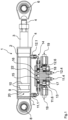
- the hydraulic upper link 1 has the piston rod 3 arranged in a cylinder tube 2 .
- the piston rod 3 protrudes from one end 4 of the cylinder tube 2 .
- a first connecting eye 6 is arranged on the end 5 of the piston rod 3 protruding from the cylinder tube 2 .
- a second connection eye 8 is arranged on the cylinder tube 2 on the side 7 of the cylinder tube 2 opposite the first connection eye 6 .
- a piston 10 having sealing elements relative to the inner surfaces of the cylinder tube 2 is arranged on the end 9 of the piston rod 3 protruding into the cylinder tube 2 .
- connections 11.1 and 12.1 connected to the interior of the cylinder tube 2 are arranged.
- connections 11.1 and 12.1 are connected to the two input connections 11.3 and 12.3 of a locking block 13 via two first hydraulic lines 11.2 and 12.2.
- These hydraulic lines 11.2 and 12.2, which are arranged between the upper link 1, which is designed as a double-acting hydraulic cylinder, are designed as line pipes made of metal.
- the blocking block 13 has two output connections 11.4 and 12.4, which are connected via hydraulic lines 11.5 and 12.5 to the hydraulic system, which has a control unit 14, of a towing vehicle carrying and/or towing an agricultural machine.
- a pilot operated check valve 15 or 16 is arranged in each of the opposite inlet 11.3 and 12.3 and outlet connections 11.4 and 12.4 of the blocking block 13 connecting line 11.6 and 12.6, a pilot operated check valve 15 or 16 is arranged in each of the opposite inlet 11.3 and 12.3 and outlet connections 11.4 and 12.4 of the blocking block 13 connecting line 11.6 and 12.6, a pilot operated check valve 15 or 16 is arranged in each of the opposite inlet 11.3 and 12.3 and outlet connections 11.4 and 12.4 of the blocking block 13 connecting line 11.6 and 12.6, a pilot operated check valve 15 or 16 is arranged in each of the opposite inlet 11.3 and 12.3 and outlet connections 11.4 and 12.4 of the blocking block 13 connecting line 11.6 and 12.6, a pilot operated check valve 15 or 16 is arranged in each of the opposite inlet 11.3 and 12.3 and outlet connections 11.4 and 12.4 of the blocking block 13 connecting line 11.6 and 12.6, a pilot operated check valve 15 or 16 is arranged in each of the opposite inlet 11.3 and 12.3 and outlet connections 11.4 and 12.4 of the
- bypass line 11.7 or 12.7 assigned.
- the respective bypass line 11.7 or 12.7 is connected to the respective opposite input 11.3 or 12.3 and output connections 11.4 or 12.4 of the locking block 13 connecting line 11.6 or 12.6 to bypass the associated pilot operated check valve 15 or 16 accordingly.
- a 2/2-way valve 17 or 18 arranged in each of these connecting lines 11.6 or 12.6, a 2/2-way valve 17 or 18 arranged in each of these connecting lines 11.6 or 12.6, a 2/2-way valve 17 or 18 arranged.
- the respective motorized actuating element 17.1 or 18.1 of the respective 2/2-way valve 17 or 18 is connected to a common control line 19.
- a switch 20 that can be actuated manually is assigned to this control line 19 .
- a current source 21 is assigned to the control line 19 .
- Each of the 2/2-way valves 17 or 18 has two possible switch positions 17.2, 17.3 or 18.2 and 18.3, one switch position being designed as a flow position 17.3 or 18.3, while the other switch position is designed as a blocking position 17.2 or 18.2.
- the two 2/2-way valves 17 and 18 each have a blocking position 17.2 and 18.2 and a flow position 17.3 and 18.3 creating a floating position of the upper link 1, respectively.
- the two 2/2-way valves 17 and 18 are connected by means of a common control line 19 which has the switch 20 .
- This control line 19 with the switch 20 are the 2/2-way valves 17 or 18 in the blocking position 17.2 or 18.2 or the flow position 17.3 or 18.3 to fix the hydraulic upper link 1 either in the set position or a free change to enable switchable.
- the two 2/2-way valves 17 and 18 must each be switched simultaneously into a blocking position or into a flow position creating a floating position of the upper link 1 .
- the length of the hydraulic upper link 1 can be controlled by means of the above-mentioned directional control valves in conjunction with the control unit 14 of the hydraulic system in conjunction with the pilot operated check valves 15 and 16 and the control line 19 and the associated motorized adjustment means 17.1 and 18.1 via the control line 19 2/ 2-way valves 17 and 18 adjustable or the floating position for the hydraulic upper link 1 can be produced.
- the control unit 14 of the hydraulic system of the tractor vehicle carrying and/or towing the agricultural machine has at least one switching valve 14A, which has at least one switching position for a blocking position 14A.1, a floating position 14A.2 and two active positions 14A.3 and 14A.4 for retracting and extending the piston rod 3 of the hydraulic upper link 1.
- the switching valve 14A of the control unit 14 In the basic position as per the circuit diagram figure 3 is shown, is the switching valve 14A of the control unit 14, so that the blocking position 14 A.1 is active.
- the pilot-operated check valves 15 and 16 block the connecting lines 11.6 and 12.6, and the bypass lines 11.7 and 12.7 are also blocked by the switch positions 17.2 and 18.2 of the directional control valves 17 and 18, respectively.
- the piston rod 3 of the upper link 1 is securely fixed and secured in the set position. In this setting, the position and thus the length of the top link is held in this position. Due to the fixed piping through the lines 11.2 and 12.2, the risk of bodily harm for people is minimized to the lowest possible risk.
- the hydraulic upper link 1 is to be lengthened by extending the piston rod 3, this is brought into the active switch position 14A.4 by actuating the changeover valve 14A.
- the pilot-operated check valve 16 is unlocked via a pressure control, hydraulic oil is pressed via the line 11.5 from the hydraulic system via the check valve 15, the connecting line 11.6 and 11.2 into the cylinder chamber of the hydraulic upper link 1.
- the piston rod 3 is extended and the upper link 1 is lengthened.
- hydraulic oil is pushed back from the cylinder chamber in which the piston rod 3 is located via the lines 12.2 and 12.6 and the pilot-operated check valve 16 into the hydraulic line 12.5 and thus into the hydraulic system.
- the switching valve 14 A is brought back into the locked position 14 A.1.
- the switch 20 is first actuated by the driver of the towing vehicle carrying and/or towing the agricultural machine so that it is closed.
- the motorized actuating elements 17.1 and 18.1 which are designed as magnets, are supplied with current since they are now connected to the power source 21 are.
- the 2/2-way valves 17 and 18 are switched over simultaneously, so that the switching position 17.3 or 18.3 forming the flow position closes the respective bypass line 11.7 and 12.7, so that the check valves 15 and 16 are bypassed in this way.
- the switching valve 14A of the tractor control device 14 is then brought into the floating position 14A.2 by the driver of the towing vehicle carrying and/or towing the agricultural machine. After this, the hydraulic upper link 1 is in the floating position.
- the upper link 1 can freely assume its length depending on the requirement of the work assignment.
- the driver of the towing vehicle carrying and/or towing the agricultural machine only needs to move the switch 20 back into its open position Session so that the power source 21 is disconnected from the control line 19 so that the motorized actuating elements 18.1, preferably designed as switching magnets, switch the respective 2/2-way valves 17 and 18 simultaneously and bring them back into the blocking position 17.2 or 18.2, so that the hydraulic cylinder is immediately fixed in its position and blocked again.
- the blocking block is therefore active again immediately after switching off and the safety function is immediately reproduced without restriction.
Landscapes
- Life Sciences & Earth Sciences (AREA)
- Engineering & Computer Science (AREA)
- Mechanical Engineering (AREA)
- Soil Sciences (AREA)
- Environmental Sciences (AREA)
- Physics & Mathematics (AREA)
- Fluid Mechanics (AREA)
- General Engineering & Computer Science (AREA)
- Zoology (AREA)
- Fluid-Pressure Circuits (AREA)
- Lifting Devices For Agricultural Implements (AREA)
Applications Claiming Priority (1)
| Application Number | Priority Date | Filing Date | Title |
|---|---|---|---|
| DE102019117081.8A DE102019117081A1 (de) | 2019-06-25 | 2019-06-25 | Vorrichtung zur Einstellung eines hydraulischen Oberlenkers |
Publications (2)
| Publication Number | Publication Date |
|---|---|
| EP3756435A1 EP3756435A1 (de) | 2020-12-30 |
| EP3756435B1 true EP3756435B1 (de) | 2023-06-07 |
Family
ID=72243065
Family Applications (1)
| Application Number | Title | Priority Date | Filing Date |
|---|---|---|---|
| EP20401033.4A Active EP3756435B1 (de) | 2019-06-25 | 2020-05-19 | Vorrichtung zur einstellung eines hydraulischen oberlenkers |
Country Status (4)
| Country | Link |
|---|---|
| EP (1) | EP3756435B1 (pl) |
| DE (1) | DE102019117081A1 (pl) |
| DK (1) | DK3756435T3 (pl) |
| PL (1) | PL3756435T3 (pl) |
Cited By (1)
| Publication number | Priority date | Publication date | Assignee | Title |
|---|---|---|---|---|
| EP4699424A1 (en) * | 2024-08-19 | 2026-02-25 | Kverneland Group Mechatronics BV | Top link assembly for an implement linkage for attaching an implement, method of operation, implement linkage for attaching an implement, and agricultural machine |
Family Cites Families (6)
| Publication number | Priority date | Publication date | Assignee | Title |
|---|---|---|---|---|
| DE1918728C3 (de) * | 1969-04-12 | 1973-12-06 | Gebrueder Eberhardt, 7900 Ulm | Drehvorrichtung fur einen Anbau drehpflug |
| DE2206195C3 (de) * | 1970-05-22 | 1974-02-28 | Weiste, Helmut, 4771 Sieningen | Laengenveraenderlicher oberlenker |
| DE19747949C2 (de) | 1997-10-30 | 2001-06-28 | Walterscheid Gmbh Gkn | Vorrichtung zur Längeneinstellung eines Oberlenkers einer Anbaueinrichtung eines Traktors |
| DE19828963A1 (de) * | 1998-06-29 | 1999-12-30 | Mannesmann Rexroth Ag | Hydraulische Schaltung |
| DE102013101761A1 (de) * | 2013-02-22 | 2014-09-11 | Amazonen-Werke H. Dreyer Gmbh & Co. Kg | An einen Schlepper anhängbare gezogene Landmaschine |
| DE102015103925A1 (de) * | 2015-03-17 | 2016-10-06 | Jan-Hendrik Wacker | Hydraulischer Oberlenker, hydraulische Dreipunktaufhängung und Verfahren zum Ankuppeln eines Nutzgerätes an ein Nutzfahrzeug |
-
2019
- 2019-06-25 DE DE102019117081.8A patent/DE102019117081A1/de active Pending
-
2020
- 2020-05-19 PL PL20401033.4T patent/PL3756435T3/pl unknown
- 2020-05-19 EP EP20401033.4A patent/EP3756435B1/de active Active
- 2020-05-19 DK DK20401033.4T patent/DK3756435T3/da active
Cited By (1)
| Publication number | Priority date | Publication date | Assignee | Title |
|---|---|---|---|---|
| EP4699424A1 (en) * | 2024-08-19 | 2026-02-25 | Kverneland Group Mechatronics BV | Top link assembly for an implement linkage for attaching an implement, method of operation, implement linkage for attaching an implement, and agricultural machine |
Also Published As
| Publication number | Publication date |
|---|---|
| EP3756435A1 (de) | 2020-12-30 |
| PL3756435T3 (pl) | 2023-08-14 |
| DE102019117081A1 (de) | 2020-12-31 |
| DK3756435T3 (da) | 2023-07-03 |
Similar Documents
| Publication | Publication Date | Title |
|---|---|---|
| DE102007053024B4 (de) | Hydraulische Lenkung | |
| DE4108915C2 (de) | Hydraulische Einrichtung zur Druckmittelversorgung eines bevorrechtigten Primärlastkreises | |
| DE2026577A1 (de) | Lenkeinrichtung | |
| DE2025040A1 (de) | Laengenveraenderlicher Oberlenker fuer eine Dreipunkt-Anhaengevorrichtung | |
| EP3756435B1 (de) | Vorrichtung zur einstellung eines hydraulischen oberlenkers | |
| DE102007020744A1 (de) | Hydraulikzylinder | |
| DE102006051541B4 (de) | Hydraulische Lenkeinrichtung | |
| EP2157320B1 (de) | Hydrauliksteuerung für einen Hydromotor | |
| DE102017004634A1 (de) | Steuervorrichtung zum Versorgen mindestens eines hydraulischen Verbrauchers | |
| DE19649187A1 (de) | Hydraulische Stabilisierungseinrichtung | |
| EP0182100B1 (de) | Hydraulische Steuereinrichtung | |
| DE3318052A1 (de) | Hydraulische steuereinrichtung | |
| DE2816212C2 (pl) | ||
| EP1003972B1 (de) | Drehwerksteuerung mit brems- und steuerventilen | |
| EP2157319B1 (de) | Hydrauliksteuerung für einen Hydromotor | |
| DE4418881A1 (de) | Hubwerkregelsystem mit Regelventil | |
| DE10036188C1 (de) | Vorrichtung zur hydraulischen Steuerung der Unterlenker eines Schleppers | |
| DE102017206581A1 (de) | Ventilanordnung für Stiel-Zylinder mit zwei Betriebszuständen | |
| DE102017100395A1 (de) | Hydraulisches Dämpfungssystem und Gelenkfahrzeug mit einem derartigen Dämpfungssystem | |
| DE3026564C2 (de) | Hydrostatischer Antrieb | |
| DE10244362B4 (de) | Hydraulische Stabilisierungseinrichtung für Fahrzeuge | |
| DE10065555B4 (de) | Lenksystem für ein Fahrzeug | |
| EP0164741B1 (de) | Prioritätsventil | |
| DE3431103A1 (de) | Hydraulische steuereinrichtung | |
| DE1505285A1 (de) | Anordnung an federnden Aufhaengevorrichtungen fuer die Endlaufraeder von Fahrzeugen mit Kettenantrieb |
Legal Events
| Date | Code | Title | Description |
|---|---|---|---|
| PUAI | Public reference made under article 153(3) epc to a published international application that has entered the european phase |
Free format text: ORIGINAL CODE: 0009012 |
|
| STAA | Information on the status of an ep patent application or granted ep patent |
Free format text: STATUS: THE APPLICATION HAS BEEN PUBLISHED |
|
| AK | Designated contracting states |
Kind code of ref document: A1 Designated state(s): AL AT BE BG CH CY CZ DE DK EE ES FI FR GB GR HR HU IE IS IT LI LT LU LV MC MK MT NL NO PL PT RO RS SE SI SK SM TR |
|
| AX | Request for extension of the european patent |
Extension state: BA ME |
|
| RAP3 | Party data changed (applicant data changed or rights of an application transferred) |
Owner name: AMAZONEN-WERK H. DREYER SE & CO. KG |
|
| RAP3 | Party data changed (applicant data changed or rights of an application transferred) |
Owner name: AMAZONEN-WERKE H. DREYER SE & CO. KG |
|
| STAA | Information on the status of an ep patent application or granted ep patent |
Free format text: STATUS: REQUEST FOR EXAMINATION WAS MADE |
|
| 17P | Request for examination filed |
Effective date: 20210630 |
|
| RBV | Designated contracting states (corrected) |
Designated state(s): AL AT BE BG CH CY CZ DE DK EE ES FI FR GB GR HR HU IE IS IT LI LT LU LV MC MK MT NL NO PL PT RO RS SE SI SK SM TR |
|
| GRAP | Despatch of communication of intention to grant a patent |
Free format text: ORIGINAL CODE: EPIDOSNIGR1 |
|
| STAA | Information on the status of an ep patent application or granted ep patent |
Free format text: STATUS: GRANT OF PATENT IS INTENDED |
|
| INTG | Intention to grant announced |
Effective date: 20230215 |
|
| GRAS | Grant fee paid |
Free format text: ORIGINAL CODE: EPIDOSNIGR3 |
|
| GRAA | (expected) grant |
Free format text: ORIGINAL CODE: 0009210 |
|
| STAA | Information on the status of an ep patent application or granted ep patent |
Free format text: STATUS: THE PATENT HAS BEEN GRANTED |
|
| AK | Designated contracting states |
Kind code of ref document: B1 Designated state(s): AL AT BE BG CH CY CZ DE DK EE ES FI FR GB GR HR HU IE IS IT LI LT LU LV MC MK MT NL NO PL PT RO RS SE SI SK SM TR |
|
| REG | Reference to a national code |
Ref country code: GB Ref legal event code: FG4D Free format text: NOT ENGLISH |
|
| REG | Reference to a national code |
Ref country code: CH Ref legal event code: EP Ref country code: AT Ref legal event code: REF Ref document number: 1571829 Country of ref document: AT Kind code of ref document: T Effective date: 20230615 |
|
| REG | Reference to a national code |
Ref country code: DE Ref legal event code: R096 Ref document number: 502020003608 Country of ref document: DE |
|
| P01 | Opt-out of the competence of the unified patent court (upc) registered |
Effective date: 20230523 |
|
| REG | Reference to a national code |
Ref country code: DK Ref legal event code: T3 Effective date: 20230628 |
|
| REG | Reference to a national code |
Ref country code: SE Ref legal event code: TRGR |
|
| REG | Reference to a national code |
Ref country code: LT Ref legal event code: MG9D |
|
| REG | Reference to a national code |
Ref country code: NL Ref legal event code: MP Effective date: 20230607 |
|
| PG25 | Lapsed in a contracting state [announced via postgrant information from national office to epo] |
Ref country code: NO Free format text: LAPSE BECAUSE OF FAILURE TO SUBMIT A TRANSLATION OF THE DESCRIPTION OR TO PAY THE FEE WITHIN THE PRESCRIBED TIME-LIMIT Effective date: 20230907 Ref country code: ES Free format text: LAPSE BECAUSE OF FAILURE TO SUBMIT A TRANSLATION OF THE DESCRIPTION OR TO PAY THE FEE WITHIN THE PRESCRIBED TIME-LIMIT Effective date: 20230607 |
|
| PG25 | Lapsed in a contracting state [announced via postgrant information from national office to epo] |
Ref country code: RS Free format text: LAPSE BECAUSE OF FAILURE TO SUBMIT A TRANSLATION OF THE DESCRIPTION OR TO PAY THE FEE WITHIN THE PRESCRIBED TIME-LIMIT Effective date: 20230607 Ref country code: NL Free format text: LAPSE BECAUSE OF FAILURE TO SUBMIT A TRANSLATION OF THE DESCRIPTION OR TO PAY THE FEE WITHIN THE PRESCRIBED TIME-LIMIT Effective date: 20230607 Ref country code: LV Free format text: LAPSE BECAUSE OF FAILURE TO SUBMIT A TRANSLATION OF THE DESCRIPTION OR TO PAY THE FEE WITHIN THE PRESCRIBED TIME-LIMIT Effective date: 20230607 Ref country code: LT Free format text: LAPSE BECAUSE OF FAILURE TO SUBMIT A TRANSLATION OF THE DESCRIPTION OR TO PAY THE FEE WITHIN THE PRESCRIBED TIME-LIMIT Effective date: 20230607 Ref country code: HR Free format text: LAPSE BECAUSE OF FAILURE TO SUBMIT A TRANSLATION OF THE DESCRIPTION OR TO PAY THE FEE WITHIN THE PRESCRIBED TIME-LIMIT Effective date: 20230607 Ref country code: GR Free format text: LAPSE BECAUSE OF FAILURE TO SUBMIT A TRANSLATION OF THE DESCRIPTION OR TO PAY THE FEE WITHIN THE PRESCRIBED TIME-LIMIT Effective date: 20230908 |
|
| PG25 | Lapsed in a contracting state [announced via postgrant information from national office to epo] |
Ref country code: FI Free format text: LAPSE BECAUSE OF FAILURE TO SUBMIT A TRANSLATION OF THE DESCRIPTION OR TO PAY THE FEE WITHIN THE PRESCRIBED TIME-LIMIT Effective date: 20230607 |
|
| PG25 | Lapsed in a contracting state [announced via postgrant information from national office to epo] |
Ref country code: SK Free format text: LAPSE BECAUSE OF FAILURE TO SUBMIT A TRANSLATION OF THE DESCRIPTION OR TO PAY THE FEE WITHIN THE PRESCRIBED TIME-LIMIT Effective date: 20230607 |
|
| PG25 | Lapsed in a contracting state [announced via postgrant information from national office to epo] |
Ref country code: IS Free format text: LAPSE BECAUSE OF FAILURE TO SUBMIT A TRANSLATION OF THE DESCRIPTION OR TO PAY THE FEE WITHIN THE PRESCRIBED TIME-LIMIT Effective date: 20231007 |
|
| PG25 | Lapsed in a contracting state [announced via postgrant information from national office to epo] |
Ref country code: SM Free format text: LAPSE BECAUSE OF FAILURE TO SUBMIT A TRANSLATION OF THE DESCRIPTION OR TO PAY THE FEE WITHIN THE PRESCRIBED TIME-LIMIT Effective date: 20230607 Ref country code: SK Free format text: LAPSE BECAUSE OF FAILURE TO SUBMIT A TRANSLATION OF THE DESCRIPTION OR TO PAY THE FEE WITHIN THE PRESCRIBED TIME-LIMIT Effective date: 20230607 Ref country code: RO Free format text: LAPSE BECAUSE OF FAILURE TO SUBMIT A TRANSLATION OF THE DESCRIPTION OR TO PAY THE FEE WITHIN THE PRESCRIBED TIME-LIMIT Effective date: 20230607 Ref country code: PT Free format text: LAPSE BECAUSE OF FAILURE TO SUBMIT A TRANSLATION OF THE DESCRIPTION OR TO PAY THE FEE WITHIN THE PRESCRIBED TIME-LIMIT Effective date: 20231009 Ref country code: IS Free format text: LAPSE BECAUSE OF FAILURE TO SUBMIT A TRANSLATION OF THE DESCRIPTION OR TO PAY THE FEE WITHIN THE PRESCRIBED TIME-LIMIT Effective date: 20231007 Ref country code: EE Free format text: LAPSE BECAUSE OF FAILURE TO SUBMIT A TRANSLATION OF THE DESCRIPTION OR TO PAY THE FEE WITHIN THE PRESCRIBED TIME-LIMIT Effective date: 20230607 Ref country code: CZ Free format text: LAPSE BECAUSE OF FAILURE TO SUBMIT A TRANSLATION OF THE DESCRIPTION OR TO PAY THE FEE WITHIN THE PRESCRIBED TIME-LIMIT Effective date: 20230607 |
|
| REG | Reference to a national code |
Ref country code: DE Ref legal event code: R097 Ref document number: 502020003608 Country of ref document: DE |
|
| PLBE | No opposition filed within time limit |
Free format text: ORIGINAL CODE: 0009261 |
|
| STAA | Information on the status of an ep patent application or granted ep patent |
Free format text: STATUS: NO OPPOSITION FILED WITHIN TIME LIMIT |
|
| PG25 | Lapsed in a contracting state [announced via postgrant information from national office to epo] |
Ref country code: SI Free format text: LAPSE BECAUSE OF FAILURE TO SUBMIT A TRANSLATION OF THE DESCRIPTION OR TO PAY THE FEE WITHIN THE PRESCRIBED TIME-LIMIT Effective date: 20230607 |
|
| 26N | No opposition filed |
Effective date: 20240308 |
|
| PG25 | Lapsed in a contracting state [announced via postgrant information from national office to epo] |
Ref country code: SI Free format text: LAPSE BECAUSE OF FAILURE TO SUBMIT A TRANSLATION OF THE DESCRIPTION OR TO PAY THE FEE WITHIN THE PRESCRIBED TIME-LIMIT Effective date: 20230607 |
|
| PG25 | Lapsed in a contracting state [announced via postgrant information from national office to epo] |
Ref country code: BG Free format text: LAPSE BECAUSE OF FAILURE TO SUBMIT A TRANSLATION OF THE DESCRIPTION OR TO PAY THE FEE WITHIN THE PRESCRIBED TIME-LIMIT Effective date: 20230607 |
|
| PG25 | Lapsed in a contracting state [announced via postgrant information from national office to epo] |
Ref country code: BG Free format text: LAPSE BECAUSE OF FAILURE TO SUBMIT A TRANSLATION OF THE DESCRIPTION OR TO PAY THE FEE WITHIN THE PRESCRIBED TIME-LIMIT Effective date: 20230607 |
|
| REG | Reference to a national code |
Ref country code: CH Ref legal event code: PL |
|
| PG25 | Lapsed in a contracting state [announced via postgrant information from national office to epo] |
Ref country code: MC Free format text: LAPSE BECAUSE OF FAILURE TO SUBMIT A TRANSLATION OF THE DESCRIPTION OR TO PAY THE FEE WITHIN THE PRESCRIBED TIME-LIMIT Effective date: 20230607 |
|
| PG25 | Lapsed in a contracting state [announced via postgrant information from national office to epo] |
Ref country code: LU Free format text: LAPSE BECAUSE OF NON-PAYMENT OF DUE FEES Effective date: 20240519 |
|
| GBPC | Gb: european patent ceased through non-payment of renewal fee |
Effective date: 20240519 |
|
| PG25 | Lapsed in a contracting state [announced via postgrant information from national office to epo] |
Ref country code: MC Free format text: LAPSE BECAUSE OF FAILURE TO SUBMIT A TRANSLATION OF THE DESCRIPTION OR TO PAY THE FEE WITHIN THE PRESCRIBED TIME-LIMIT Effective date: 20230607 Ref country code: LU Free format text: LAPSE BECAUSE OF NON-PAYMENT OF DUE FEES Effective date: 20240519 Ref country code: CH Free format text: LAPSE BECAUSE OF NON-PAYMENT OF DUE FEES Effective date: 20240531 |
|
| REG | Reference to a national code |
Ref country code: BE Ref legal event code: MM Effective date: 20240531 |
|
| PGFP | Annual fee paid to national office [announced via postgrant information from national office to epo] |
Ref country code: SE Payment date: 20250310 Year of fee payment: 6 |
|
| PG25 | Lapsed in a contracting state [announced via postgrant information from national office to epo] |
Ref country code: IE Free format text: LAPSE BECAUSE OF NON-PAYMENT OF DUE FEES Effective date: 20240519 |
|
| PG25 | Lapsed in a contracting state [announced via postgrant information from national office to epo] |
Ref country code: BE Free format text: LAPSE BECAUSE OF NON-PAYMENT OF DUE FEES Effective date: 20240531 |
|
| PGFP | Annual fee paid to national office [announced via postgrant information from national office to epo] |
Ref country code: FR Payment date: 20250310 Year of fee payment: 6 Ref country code: PL Payment date: 20250314 Year of fee payment: 6 |
|
| PG25 | Lapsed in a contracting state [announced via postgrant information from national office to epo] |
Ref country code: GB Free format text: LAPSE BECAUSE OF NON-PAYMENT OF DUE FEES Effective date: 20240519 |
|
| PGFP | Annual fee paid to national office [announced via postgrant information from national office to epo] |
Ref country code: DE Payment date: 20250325 Year of fee payment: 6 |
|
| PGFP | Annual fee paid to national office [announced via postgrant information from national office to epo] |
Ref country code: DK Payment date: 20250516 Year of fee payment: 6 |
|
| PGFP | Annual fee paid to national office [announced via postgrant information from national office to epo] |
Ref country code: IT Payment date: 20250422 Year of fee payment: 6 |
|
| PGFP | Annual fee paid to national office [announced via postgrant information from national office to epo] |
Ref country code: AT Payment date: 20250425 Year of fee payment: 6 |
|
| PG25 | Lapsed in a contracting state [announced via postgrant information from national office to epo] |
Ref country code: CY Free format text: LAPSE BECAUSE OF FAILURE TO SUBMIT A TRANSLATION OF THE DESCRIPTION OR TO PAY THE FEE WITHIN THE PRESCRIBED TIME-LIMIT; INVALID AB INITIO Effective date: 20200519 |
|
| PG25 | Lapsed in a contracting state [announced via postgrant information from national office to epo] |
Ref country code: HU Free format text: LAPSE BECAUSE OF FAILURE TO SUBMIT A TRANSLATION OF THE DESCRIPTION OR TO PAY THE FEE WITHIN THE PRESCRIBED TIME-LIMIT; INVALID AB INITIO Effective date: 20200519 |