EP3755986B1 - Bordeigene antriebstestvorrichtung - Google Patents
Bordeigene antriebstestvorrichtung Download PDFInfo
- Publication number
- EP3755986B1 EP3755986B1 EP19780743.1A EP19780743A EP3755986B1 EP 3755986 B1 EP3755986 B1 EP 3755986B1 EP 19780743 A EP19780743 A EP 19780743A EP 3755986 B1 EP3755986 B1 EP 3755986B1
- Authority
- EP
- European Patent Office
- Prior art keywords
- interface assembly
- testing
- chamber
- support member
- vessel
- Prior art date
- Legal status (The legal status is an assumption and is not a legal conclusion. Google has not performed a legal analysis and makes no representation as to the accuracy of the status listed.)
- Active
Links
Images


Classifications
-
- F—MECHANICAL ENGINEERING; LIGHTING; HEATING; WEAPONS; BLASTING
- F01—MACHINES OR ENGINES IN GENERAL; ENGINE PLANTS IN GENERAL; STEAM ENGINES
- F01D—NON-POSITIVE DISPLACEMENT MACHINES OR ENGINES, e.g. STEAM TURBINES
- F01D17/00—Regulating or controlling by varying flow
- F01D17/02—Arrangement of sensing elements
-
- B—PERFORMING OPERATIONS; TRANSPORTING
- B64—AIRCRAFT; AVIATION; COSMONAUTICS
- B64G—COSMONAUTICS; VEHICLES OR EQUIPMENT THEREFOR
- B64G1/00—Cosmonautic vehicles
- B64G1/10—Artificial satellites; Systems of such satellites; Interplanetary vehicles
- B64G1/1078—Maintenance satellites
-
- B—PERFORMING OPERATIONS; TRANSPORTING
- B64—AIRCRAFT; AVIATION; COSMONAUTICS
- B64G—COSMONAUTICS; VEHICLES OR EQUIPMENT THEREFOR
- B64G7/00—Simulating cosmonautic conditions, e.g. for conditioning crews
-
- F—MECHANICAL ENGINEERING; LIGHTING; HEATING; WEAPONS; BLASTING
- F01—MACHINES OR ENGINES IN GENERAL; ENGINE PLANTS IN GENERAL; STEAM ENGINES
- F01D—NON-POSITIVE DISPLACEMENT MACHINES OR ENGINES, e.g. STEAM TURBINES
- F01D21/00—Shutting-down of machines or engines, e.g. in emergency; Regulating, controlling, or safety means not otherwise provided for
- F01D21/003—Arrangements for testing or measuring
-
- F—MECHANICAL ENGINEERING; LIGHTING; HEATING; WEAPONS; BLASTING
- F02—COMBUSTION ENGINES; HOT-GAS OR COMBUSTION-PRODUCT ENGINE PLANTS
- F02K—JET-PROPULSION PLANTS
- F02K9/00—Rocket-engine plants, i.e. plants carrying both fuel and oxidant therefor; Control thereof
- F02K9/96—Rocket-engine plants, i.e. plants carrying both fuel and oxidant therefor; Control thereof characterised by specially adapted arrangements for testing or measuring
-
- G—PHYSICS
- G01—MEASURING; TESTING
- G01M—TESTING STATIC OR DYNAMIC BALANCE OF MACHINES OR STRUCTURES; TESTING OF STRUCTURES OR APPARATUS, NOT OTHERWISE PROVIDED FOR
- G01M15/00—Testing of engines
- G01M15/02—Details or accessories of testing apparatus
-
- G—PHYSICS
- G01—MEASURING; TESTING
- G01M—TESTING STATIC OR DYNAMIC BALANCE OF MACHINES OR STRUCTURES; TESTING OF STRUCTURES OR APPARATUS, NOT OTHERWISE PROVIDED FOR
- G01M15/00—Testing of engines
- G01M15/14—Testing gas-turbine engines or jet-propulsion engines
Definitions
- the present disclosure relates to an automated testing apparatus and components associated with a testing facility and simulation chamber for a satellite-based on-board propulsion (OBP) system.
- OBP on-board propulsion
- OBP systems are tested in a ground testing facility to determine performance parameters before being delivered to customers for integration with a satellite. This testing produces a deliverable of test data to prove the OBP system's performance and is generally a labor-intensive and time consuming process. Lifetime ground test equipment for an ion thruster is described in CN 105 067 293 A .
- the lifetime ground test equipment for the ion thruster comprises a main cabin vacuum container, a gate valve, an auxiliary cabin vacuum container, a vacuum pumping system, an ion beam target, an anti-sputtering screen, a thruster mobile mechanism, a quartz crystal microbalance QCM, a thruster divergence angle measuring system, a grid corrosion on-line monitoring system, a ground test power supply system, an equipment control system, a xenon supply system, a repressing system, a cooling water system, a pneumatic element air supply system, a liquid nitrogen storage and supply system, and a shooting illumination system.
- a vacuum arc thruster is described in WO 2016/181360 A1 .
- the vacuum arc thruster includes an anode arrangement, a cathode, an insulator which is located between the anode arrangement and the cathode, and a control arrangement.
- the anode arrangement includes at least two anode elements which are spaced from each other around the cathode.
- the control arrangement is operatively connected to the cathode and each of the anode elements and is configured to switch each anode element between an active state and an inactive state. When an anode element is in its active state, the control arrangement utilises the anode element in order to generate a vacuum arc pulse between the said anode element and the cathode. When an anode element is however in its inactive state, the particular anode element is not used for vacuum arc generation.
- a test campaign for qualifying a commercial off-the-shelf cold gas micro-propulsion system is described in Migliaccio et al: "Vacuum testing of a micropropulsion system based on solid propellant cool gas generators", 61st International Astronautical Congress, Prague, Czech Republic, 27 September - 1 October 2010, 29 September 2010 .
- An ion test device is described in JP 2015 182706 A .
- the ion engine test device jets an ion beam from an ion engine toward a beam target installed in a vacuum tank, in which a shroud kept in an ultralow temperature is provided, to conduct a test of the ion engine.
- the ion engine test device includes: a cylindrical cryopanel which is provided along an inner peripheral surface of the vacuum tank in a space between the ion engine and the beam target; and a direct attachment type refrigerator which cools the cryopanel.
- a vacuum chamber to be used for testing an engine is described in JP S62 258900 A .
- the vacuum chamber is adapted to accommodate the ion engine.
- a vacuum container is disposed to face the ion engine in the vacuum container and receiv ions emitted from the ion engine to generate energy.
- a beam dump absorbs the ions emitted from the ion engine.
- An insulating member has an opening through which ions emitted from the ion engine are incident.
- a heat insulating material covers the beam dump and the inner surface of the vacuum container.
- a baffle shields a heat ray having a protrusion on the side of the beam dump and a cryopanel for evacuation provided in an area shadowing a heat ray incident from the outer wall of the
- the disclosure provides an interface assembly for connecting an on-board propulsion system to a testing facility.
- the interface assembly includes a support member configured for coupling to a manipulation system and a mounting member configured for coupling to the on-board propulsion system.
- a plurality of channels extends between and couples the mounting member to the support member.
- the disclosure provides, in another aspect, a testing system for testing an on-board propulsion system.
- the testing system includes a vessel, a vacuum pump in operative communication with the vessel, and a plurality of sensors positioned within the vessel.
- the testing system further includes a manipulation system, a portion of which is automatically movable toward and away from the vessel.
- the testing system further includes an interface assembly having a support member configured for coupling to the manipulation system and a mounting member configured for coupling to the on-board propulsion system.
- a plurality of channels extends between and couples the mounting member to the support member.
- the disclosure provides, in yet another aspect, a method for testing an on-board propulsion system within a testing facility.
- the method includes coupling the on-board propulsion system to an interface assembly and coupling the interface assembly to a manipulation system.
- the method also includes moving, via the manipulation system, the interface assembly toward a chamber of the testing facility such that at least a portion of the interface assembly is within the chamber.
- the method further includes connecting the interface assembly to the testing facility such that the interface assembly is configured to receive a fluid from the testing facility.
- the method additionally includes de-coupling the manipulation system from the interface assembly, operating the on-board propulsion system, and measuring and recording an output thrust force of the on-board propulsion system.
- FIG. 1 illustrates a testing assembly 1010 for testing a satellite-based OBP system.
- the testing assembly 1010 includes an interface assembly 1014 configured for connection with the OBP system and for connection with a portion of a testing facility 1022.
- the testing assembly 1010 also includes a manipulation system 1026.
- the illustrated manipulation system 1026 is a robotic arm 1024 supported by a base 1025.
- the robotic arm 1024 is configured for movement, i.e., rotating and translating, of the interface assembly 1014 relative to the testing facility 1022.
- the illustrated robotic arm 1024 includes a plurality of segments 1015 connected by joints 1016 for moving the interface assembly 1014.
- the manipulation system may instead take other forms, such as that of a mobile cart, e.g., on wheels or rails, to move the interface assembly 1014 relative to the testing facility 1022.
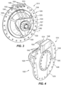
- FIGS. 3-4 illustrate the interface assembly 1014 including an interface member or body 1020.
- the body 1020 includes a mounting member 1027 (i.e., in the form of a plate or flange) and a support member 1028 (i.e., in the form of a plate or disc) spaced from and connected by legs 1029 to the mounting member 1027.
- the interface assembly includes three spacers or legs 1029, in which each leg 1029 is positioned at and extends from a corner of the mounting member 1027.
- the mounting member 1027 is shaped to accommodate the legs 1029, which may be more or fewer than three in number in some embodiments.
- the mounting member 1027 may be adjacent the support member 1028, either abutting or minimally spaced therefrom.
- the body 1020 may include only one of the mounting member 1027 and the support member 1028.
- the body 1020 may be generally cuboid in shape and accordingly presents a plurality of sides or faces.
- the body 1020 may be one of many shapes that presents a plurality of surfaces, as will be further explained below.
- a surface of the mounting member 1027 facing away from the support member 1028 is a first surface or side 1030 of the interface assembly 1014.
- a bracket 1034 is secured (by fasteners) to the first side 1030 (i.e., the mounting member 1027).
- the bracket 1034 is configured for coupling to an OBP system 1082 such that the OBP system 1082 extends from and is supported by the mounting member 1027.
- the mounting member 1027 may serve as the aforementioned bracket or otherwise be in the form of a bracket, brace, arm, truss, etc., and may closely couple the OBP system 1082 to the body 1020 or couple the OBP system 1082 at a spaced distance from the body 1020, as alternatively described herein.
- the mounting member 1027 itself may form any one of the sides of the body 1020 and/or the bracket 1034 may be positioned on any one of the sides of the body 1020.
- the support member 1028 is generally planar and has a generally circular shape. More specifically, the support member 1028 is cylindrically shaped and defines a longitudinal axis A therethrough. The mounting member 1027 is spaced from the support member 1028 along the longitudinal axis A. In addition, the support member 1028 is sized relatively larger than the mounting member 1027, as will be further explained. A surface of the support member 1028 facing away from the mounting member 1027 is a second side 1038 ( FIG. 4 ) of the interface assembly 1014. A mount 1040 is secured to the second side 1038 (such as by fasteners). The illustrated mount 1040 is itself a plate having a generally circular shape and is sized relatively smaller than the support member 1028. In some embodiments, the mount 1040 is integrally formed as one piece with the support member 1028. The interface assembly 1014 is removably couplable to an end of the robotic arm 1024 ( FIG. 5 ) via the mount 1040.
- the illustrated first side 1030 and the second side 1038 are generally planar and provide attachment surfaces for the coupling of each of the OBP system 1082 and the end of the robotic arm 1024 to the interface assembly 1014.
- the second side 1038 is preferably opposite the first side 1030 such that the mount 1040 is on the other side of the body 1020 from the bracket 1034, but that need not be the case in all embodiments.
- the interface assembly 1014 includes a plurality of channels 1042.
- the channels 1042 are supported by the body 1020.
- the illustrated channels extend between the mounting member 1027 and the support member 1028.
- the interface assembly 1014 includes three channels 1042. In other embodiments, the interface assembly 1014 may include two or fewer or four or more channels 1042.
- each of the channels 1042 is positioned at least partially internally within the mounting member 1027 and partially internally within the support member 1028.
- the channels 1042 are routed to transmit electrical signals, liquids, gases, or other materials from an entry point at a body surface to an exit point.
- the channels 42 may therefore be lined or unlined, and may themselves contain wire, hose, pipe, or other forms of conduit to promote the passage of the signals or materials.
- the first and second channels 1042 may be routed to transmit electrical signal
- the third channel 1042 may be routed to transmit fluid such as propellant.
- the channels 1042 are formed by conduit (e.g., pipe) extending between connectors or ports positioned on the first side 1030 (not shown; axially behind the bracket 1034 from the frame of reference of FIG. 3 ) of the mounting member 1027 and connectors or ports 1054 of the support member 1028.
- the illustrated channels 1042 extend from the ports on the first side 1030 as passageways through an edge 1044 of the mounting member 1027 to an intermediate side 1046 of the interface assembly 1014.
- the channels 1042 then extend as passageways through the support member 1028 from the intermediate side 1046 to at or near a top edge 1048 of the support member 1028.
- the channels 1042 enter and exit the support member 1028 at the intermediate side 1046.
- the mounting member 1027 and the support member 1028 define passages or passageways and the channels 1042 are formed by conduit (e.g., flexible hose) portions that extend from the ports on the first side 1030 through the passages of the mounting member 1027 and the passages of the support member 1028 to the ports 1054 of the support member 1028.
- the passages may be formed during manufacture of the mounting member 1027 and the support member 1028 (e.g., by casting) and/or may be formed by boring out the passages in the mounting member 1027 and the support member 1028 after manufacture.
- the "channels" are instead wire, hose, pipe, or other conduit routed wholly or partially along an outside surface of the body 1020 and/or the outside surfaces of the support member 1028 and the mounting member 1027.
- the body 1020 is one piece and the channels are alternatively formed by the passages such that the channels are completely embedded within the body 1020.
- the channels are a mix of internal, partially embedded, or external wires, hoses, pipes, or other conduits extending from an entry point on or in the body 1020 to an exit point on or in the body 1020.
- the passages are lined with suitable material for forming the channels such that the channels are formed in part by the passages and the conduit extends from the passages to the ports.
- all of the ports i.e., the ports on the first side 1030 and the ports 1054 may be located on the same or different sides, or in any combination thereof, of the body 1020.
- only a single channel is provided, or a single channel is configured to contain or permit passage of multiple fluids, or a combination of electrical signals, liquids, gases, or other materials in a manner as described herein.
- Connectors 1074 ( FIG. 3 ), e.g., "quick connect” or similar connectors for coupling provide coupling points configured to removably join the ports of the mounting member 1027 and the ports 1054 of the support member 1028 with external connections in the form of wire, hose, pipe, and other conduit, which will be further described below.
- the connectors 1074 may be integrally formed with the ports 1054 or connected to the ports of the first side 1030 and/or the ports 1054 such that the connectors 1074 extend from the respective ports 1054.
- the ports of the mounting member 1027 are in communication with the OBP system 1082 (such as by similar connectors 1074 as described above) such that the channels 1042 are connected between the OBP system 1082 and the ports 1054.
- the bracket 1034 includes mating connectors such that when the OBP system 1082 is secured by the bracket 1034 to the first side 1030, the bracket 1034 also fluidly connects the OBP system 1082 with the channels 1042 of the interface assembly 1014.
- the OBP system 1082 is fluidly connected with the channels 1042 through the bracket 1034.
- the bracket 1034 includes ports and channels extending therebetween similar to the channels 1042 of the body 1020 which are routed to transmit electrical signals, liquids, gases, or other materials.
- the bracket 1034 includes ports for fluidly connecting between the ports on the first side 1030 of the body 1020 and connection points of the OBP system 1082.
- the wire, hose, pipe, or other conduit extends between the ports and/or the bracket 1034 itself may define passages extending between the ports for forming the channels of the bracket 1034.
- the ports 1054 of the support member 1028 are fluidly connected to the testing facility 1022, as further discussed below. Therefore, the OBP system 1082 may be fluidly connected to the testing facility 1022 via the channels 1042.
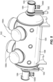
- FIG. 5 illustrates one embodiment of the testing facility 1022 including a vessel or chamber 1080.
- the chamber 1080 includes a plurality of lateral chambers 1084 and a main test chamber 1088.
- the chamber 1080 includes two lateral chambers 1084.
- the chamber 1080 may include one or three or more chambers 1080 or sub chambers (i.e., test chamber 1088, lateral chambers 1084).
- the two illustrated lateral chambers 1084 are positioned at opposite ends of the test chamber 1088.
- the two lateral chambers 1084 may be termed as the OBP system engagement chambers.
- the testing facility 1022 further includes a plurality of connection points 1090 for connection to vacuum pumps 1096.
- the vacuum pump 1096 may be in operative communication with the chamber 1080.
- the test chamber 1088 includes four openings 1090, and each lateral chamber 1084 includes one opening 1090.
- the testing facility 1022 may include one or more openings 1090 for connection to a vacuum pump 1096.
- the illustrated openings 1090A of the test chamber 1088 are configured for connection with a cryopump or cryogenic pump 1096A.
- Each opening 1090B of the lateral chamber 1084 is configured for connection with a turbomolecular pump 1096B, an example of which is a stand-in Pfeiffer vacuum turbopump sold by Pfeiffer Vacuum.
- a turbomolecular pump 1096B an example of which is a stand-in Pfeiffer vacuum turbopump sold by Pfeiffer Vacuum.
- Other pumps suitable therewith include ion pumps, cryopumps, or diffusion pumps.
- the chamber 1080 may comprise one or three or more vacuum pumps 1096 for each chamber 1080 or sub chamber 1084, 1088, or with only one vacuum pump 1096 serving all chambers 1080 or sub chambers 1084, 1088.
- each of the lateral chambers 1084 is separated from the test chamber 1088 by a partition or divider 1092.
- the divider is a valve 1092.
- the valve 1092 is movable from a first open position in which the associated lateral chamber 1084 and the test chamber 1088 are in fluid communication, to a second closed position in which the associated lateral chamber 1084 and the test chamber 1088 are not in fluid communication.
- no valve or other partition exists between the lateral chamber(s) 1084 and the test chamber 1088.
- an end 1086 of each lateral chamber 1084 includes a rim 1093 forming an opening 1094 fluidly connecting an internal volume 1076 of the lateral chamber with the external environment (i.e., of a laboratory or testing room).
- one of the lateral chambers 1084 i.e., the one to the right from the frame of reference of FIG. 5
- the other of the lateral chambers 1084 i.e., the one to the left from the frame of reference of FIG. 5
- An outer circumferential portion 1078 FIG.
- the support member 1028 of the interface assembly 1014 cooperates with the rim 1093.
- the support member 1028 is sized corresponding to a circumference of the rim 1093 such that the support member 1028 is engageable with the entire circumference of the rim 1093.
- an internal surface 1079 (e.g., "chamber wall") of the lateral chamber 1084 is generally cylindrical in view of conditions during testing, as will be further explained.
- the rim 1093 may also form a portion of and be termed as the chamber wall.
- the lateral chamber 1084 includes a supply assembly 1105.
- the illustrated supply assembly 1105 is positioned at a top 1101 of the mount chamber 1084 adjacent the rim 1093, as illustrated, but in other embodiments could be positioned about the respective lateral chamber 1084 at other locations.
- the supply assembly 1105 is connected (by connectors not shown) to external supplies (e.g., a propellant supply, a power supply, water, etc.) for supplying the respective material through ports 1102 to the ports 1054 of the interface assembly 1014.
- the ports 1054 form the male connection and the ports 1102 form the female connection.
- the ports 1102 may include connectors 1074 extending from the ports 1102 for connecting to the ports 1054 of the interface assembly 1014.
- the interface assembly 1014 and/or the testing facility 1022 may further contain diagnostic equipment such as diagnostic probes, sensors, strain gauges, and other testing components 1098.
- the testing facility 1022 includes a plurality of sensors 1098 positioned within the chamber 1080 (including the lateral chamber 1084).
- the sensors 1098 are configured to measure the temperature, emitted exhaust beam, and other testing and environmental parameters that occur during testing within the chamber 1080.
- the interface assembly 1014 may include a force measurement system, for instance a strain gauge load cell (not shown) positioned intermediate the OBP system 1082 and the first side 1030 (i.e., between the bracket 1034 and the OBP system 1082) or at another suitable location.
- the strain gauge load cell is configured to measure the output thrust force produced by the OBP system 1082 during testing.
- the testing components 1098 are in electrical communication with a controller 1120.
- the controller 1120 may form a part of a test control and data recording system for collecting data indicated by the sensors 1098.
- the controller 1120 may send the data to a main controller or control system or may itself be the main controller for controlling operation of the testing facility 1022.
- the controller 1120 is operable to control and/or initiate testing parameters such as fluid flow, electrical signals, etc., to the OBP system 1082 and to operate diagnostic equipment and the sensors 1098 as part of the testing procedure.
- the controller 1120 may be further in operable communication with the vacuum pumps 1096, the valve 1092, and the manipulation system 1026.
- the load cell may be electrically connected to the controller 1120 via the channels 1042 routed to transmit electrical signals.
- the robotic arm 1024 of the manipulation system 1026 is configured to move the interface assembly 1014 between a first, disengaged position ( FIGS. 1 and 6 ) and a second, engaged position ( FIG. 7 ).
- the interface assembly 1014 is not fluidly connected or otherwise coupled to the respective lateral chamber 1084.
- the manipulation system 1026 supports the interface assembly 1014 in the disengaged position ( FIG. 1 ).
- the interface assembly 1014 i.e., the support member 1028
- the channels 1042 are fluidly connected to the ports 1102 of the supply assembly 1100.
- the manipulation system 1026 is positioned such that some or all of it may be external to the lateral chamber 84 ( FIG. 1 ). More specifically, all or a portion of the manipulation system 1026 may be positionable within a transfer location 1109 or otherwise configured for access to both the transfer location 1109 and the lateral chamber 1084.
- the interface assembly 1014 is partially insertable (by the manipulation system 1026) into a lateral chamber 1084 and removably couplable to the end 1086 of the lateral chamber 1084 (i.e., the OBP system engagement chamber) to seal the internal volume 1076.
- the outer circumferential portion 1078 of the support member 1028 is coupled to the rim 1093, such as by fasteners (e.g., bolts), and the mounting member 1027 (having the OBP system 1082) extends from the support member 1028 by the legs 1029 within the lateral chamber 1084.
- the mounting member 1027 is sized smaller than the support member 1028 for fitting within the lateral chamber 1084.
- the support member 1028 of the interface assembly 1014 is configured as a cover for enclosing the opening 1094.
- the OBP system 1082 is positioned within the lateral chamber 1084 when the support member 1028 is secured to the lateral chamber 1084.
- the coupling of the interface assembly 1014 to the rim 1093 may be automatic and/or manually performed.
- the robotic arm 1024 may position the support member 1028 adjacent the rim 1093 and an operator may manually drive fasteners around the outer circumferential portion 1078 of the support member 1028.
- the coupling process may be completely automatic (e.g., another robot configured to secure the support member 1028 to the rim 1093, or automated locks or connectors (e.g., pneumatic, electric) to secure the support member 1028 to the rim 1093).
- the ports 1054 of the interface assembly 1014 are fluidly coupled with the ports 1102 of the supply assembly 1105 concurrently with or after the interface assembly 1014 is secured to the rim 1093 of the respective lateral chamber 1084.
- the ports 1054 of the support member 1028 are fluidly connected when the interface assembly 1014 is mounted or otherwise secured to the lateral chamber 1084.
- an end of each of the channels 1042 having the port 1054 is received in the respective port 1102 of the supply assembly 1100 when the support member 1028 is mounted flush with the rim 1093.
- the ports 1054 may be connected with the ports 1102 of the supply assembly 1105 by clamps, pneumatic locks, or other types of connectors/fasteners that fluidly couple the ports 1054, 1102 together. Operational engagement of the interface assembly 1014 with the vessel 1080, to be further described, may therefore be fully automated.
- FIG. 10 illustrates an alternative embodiment of the OBP system engagement chamber 1084 in which the supply assembly 1105 is at least partially within the chamber 1084.
- the outer circumferential portion 1078 of the support member 1028 is sized such that the support member 1028 fits wholly within the lateral chamber 1084.
- the ports 1102 of the supply assembly 1105 are also positioned on the portion of the supply assembly 1105 that is within the lateral chamber 1084 such that the fluid connection between the interface assembly 1014 and the supply assembly 1100 is within the lateral chamber 1084.
- a cover 1095 is secured to the opening 1094 after the interface assembly 1014 is mounted within the lateral chamber 1084 for sealing the chamber 1084.
- the cover 1095 may be hinge-mounted or securable in a manner again permitting operational engagement of the interface assembly 1014 with the vessel 1080, to be further described, to be fully automated.
- the supply assembly 1105 of FIG. 10 may include a performance measurement stand (i.e., a stand including and/or electrically connected to the testing components 1098, such as the sensors, within the chamber 1080).
- the performance measurement stand may include an inverted pendulum stand having non-contact actuators such as electromagnets.
- the inverted pendulum stand determines the output thrust force produced by the OBP system 1082 during testing based on how much force the electromagnets generate to maintain the OBP system 1082/interface assembly 1014 in an upright position (relative to the lateral chamber 1084).
- the performance measurement stand may be a torsional pendulum, which determines output thrust force produced by the OBP system during testing based on an angular displacement of a torsional spring.
- the testing facility 1022 may include the sensors and other measurement components suitable to measure the thrust output, as well as the temperature, emitted exhaust beam, and other testing and environmental parameters that occur during testing within the chamber 1080.
- the OBP system 1082 is coupled to the interface assembly 1014 via the mounting member 1027/bracket 1034, step 150.
- This step may be manual or semi-automated and/or facilitated by additional equipment, and may include coupling the ports of the first side 1030 with mating ports of the bracket 1034 and OBP system 1082 using external connections such as the connectors 1074 or otherwise in the form of wire, hose, pipe, or other conduit configured to transmit electrical signals, liquids, gases, or other materials as necessary for testing.
- Step 150 occurs in the transfer location 1109 but may in some instances occur near or in the lateral chamber 1084.
- the OBP system 1082 is coupled to the interface assembly 1014 in a separate procedure and then the OBP system 1082/interface assembly 1014 is positioned within the transfer location 1109.
- the interface assembly 1014 is coupled to the manipulation system 1026 via the mount 1040.
- the manipulation system 1026 which may be controlled by the controller 1120 or independently controlled, and in particular the robotic arm portion 1024 thereof, is brought into proximity with the mounting member 1040 and coupled thereto without manual assistance.
- the interface assembly 1014 may first be coupled to the manipulation system 1026 and thereafter the OBP system 1082 is coupled to the mounting member 1027/bracket 1034.
- step 158 the interface assembly 1014 is connected to or engaged with the testing facility 1022.
- the interface assembly 1014 is coupled to the end 1086 of the lateral chamber 1084 and is operationally connected to the testing facility 1022 via the supply assembly 1105.
- step 158 may include moving the interface assembly 1014/OBP system 1082 from the transfer location 1109 toward the lateral chamber 1084.
- Step 158 may further include positioning the support member 1028 adjacent the rim 1093 of the lateral chamber 1084 such that the mounting member 1027 and the OBP system 1082 is positioned within the lateral chamber 1084.
- Step 158 may further include securing the support member 1028 of the interface assembly 1014 to the rim 1093.
- step 158 includes moving the interface assembly 1014/OBP system 1082 from the transfer location 1109 into the lateral chamber 1084.
- Step 158 further includes positioning the interface assembly 1014 onto the supply assembly 1105.
- the manipulation system 1026 may only need to position the interface assembly 1014 proximate the supply assembly 1105, with the weight of the interface assembly 1014/OBP system 1082 wholly or partially supported by the manipulation system 1026.
- the ports 1054 (or its connectors 1074) are coupled to the ports 1102 the supply assembly 1105. In some embodiments, positioning of the interface assembly 1014 adjacent the supply assembly 1105 results in concurrent and automatic coupling of the connectors 1074 of the ports 1054 with the supply ports 1102 (or its connectors). In one example, the channels 1042 are received in the ports 1102 when the interface assembly 1014 is moved into the engaged position for the automatic connection to the supply assembly 1105. In other embodiments, the flexible wires/hose/conduit, etc. extend from the supply ports 1102 to the above-mentioned connectors 1074, and may require manual assistance for coupling thereto.
- the OBP system 1082 is in electrical/gas/liquid/fluid communication with the testing facility 1022 through the interface assembly 1014 (via the connectors 1074 and the ports 1102, 1054). Specifically, electrical signals (power and data), liquids, gases, or other materials can be transferred from the testing facility 1022 to the OBP system 1082.
- a fourth step 162 if the interface assembly 1014/OBP system 1082 is secured to the rim 1093 or within the chamber 1084, the manipulation system 1026 is subsequently decoupled from the interface assembly 1014 (the mount 1040) and may further be moved (away) from the lateral chamber 1084.
- the controller 1120 activates the vacuum pumps 96, 1096A, 1096B to evacuate air in the lateral and test chambers 1084, 1088 to simulate a space environment.
- the controller 1120 may be further configured to manipulate the valve 1092 from a closed position to an open position for introducing the OBP system1082 to the test chamber 1088.
- the OBP system 1082 is no longer isolated from the test chamber 1088 once the valve 1092 is opened.
- the valve 1092 may only be opened once the controller 1120 has determined that the OBP system 1082 is properly connected to the supply assembly 1100/performance measurement stand and the chamber 1080 has been evacuated to appropriately simulate a space environment. At this point, the OBP system 1082 is ready for testing.
- the controller 1120 enables operation of the OBP system 1082.
- the controller 1120 is configured to activate the supply assembly 1105 to provide the desired electrical signal(s), fluid (e.g., propellant), gas or other materials from the supply assembly 1105 to the OBP system 1082 through the interface assembly 1014.
- a seventh step 174 the strain gauge load cell or the inverted pendulum stand or the torsional pendulum stand measures a resultant output thrust force of the OBP system 1082.
- This step 174 may further include measuring, using the diagnostic probes or sensors 1098 (some of which may be located on the stand), and other performance test data such as temperature, pressure, etc., within the lateral and test chambers 84, 88.
- the controller 1120 having the test control and data recording system monitors and records the performance data including the resultant output thrust force and associated parameters (e.g., propellant/fluid flow or consumption rate).
- This step may further include creating a report and/or analytic graphs of the performance test data.
- the test control and data recording system is configured to produce a deliverable of test data to prove the OBP system's performance.
- the controller disables the OBP system 1082. Specifically, the controller deactivates passage of electrical signals and fluids through the supply assembly 1105 and to the interface assembly 1014.
- a ninth step 182 the OBP system 1082 is removed from the chamber 1080 after testing is completed.
- This step 182 may include deactivating the vacuum pumps 1096 by the controller 1120 to return the pressure within the chamber 1080 to atmospheric. Subsequently, the controller 1120 may control the manipulation system 1026 to move the robotic arm adjacent the support member 1028 (i.e., external to or within the lateral chamber 1084). This step 182 may further include re-coupling the robotic arm 1024 to the mounting member 1040 automatically or with manual assistance. The controller 1120 is then operable to control the manipulation system 1026 to move the robotic arm 1204 to return the interface assembly 1014/OBP system 1082 to the transfer location 1109, after which the OBP system 1082 is detached from the interface assembly 1014.
- the testing of the OBP system 1082 is substantially, if not wholly, automated.
- the controller 1120 or other control system is operable to control selective connection and movement of the manipulation system 1026, establish a testing environment within the chamber 1080 using the vacuum pumps 1096 and the valve 1092, transfer signals and testing materials such as electrical power and data and liquids, gases, etc. to the OBP system 1082 from the testing facility 1022, and measure and record test data.
- all testing of the OBP system 1082, from coupling to decoupling of the interface assembly 1014 may be completed in fewer than 8 hours. In other embodiments, the testing may be completed in fewer than 6 hours.
- the present disclosure provides an automated OBP performance testing apparatus that significantly shortens the time required to conduct a performance test, reduces or eliminates the need for human interaction and assistance in performing the test, reduces the amount of human labor required to collect and report test results, reduces the test-to-test variability that is associated with human manual labor, and provides a unique interface assembly that can accommodate a variety of OBP variants without facility modification.
- the disclosure is amenable to complete robotic and unassisted operation, although operators may perform one or several assembly or testing functions.
- the system of the disclosure permits significant reduction in the amount of time and labor required to conduct testing on an OBP system.
Landscapes
- Engineering & Computer Science (AREA)
- Physics & Mathematics (AREA)
- General Physics & Mathematics (AREA)
- Remote Sensing (AREA)
- Astronomy & Astrophysics (AREA)
- Chemical & Material Sciences (AREA)
- Combustion & Propulsion (AREA)
- Aviation & Aerospace Engineering (AREA)
- Mechanical Engineering (AREA)
- General Engineering & Computer Science (AREA)
- Testing Of Devices, Machine Parts, Or Other Structures Thereof (AREA)
- Manipulator (AREA)
Claims (13)
- Testsystem (1022) zum Testen eines Bord-Antriebssystems (1082), wobei das Testsystem Folgendes umfasst:ein Gefäß (1080);eine Vakuumpumpe (1096), die in betriebsfähiger Verbindung mit dem Gefäß (1080) steht;eine Vielzahl von Sensoren (1098), die innerhalb des Gefäßes (1080) positioniert ist;ein Handhabungssystem (1026), wovon ein Abschnitt automatisch in Richtung des Gefäßes (1080) und von diesem weg bewegt werden kann;eine Schnittstellenanordnung (1014), Folgendes umfassend:ein Stützelement (1028), das zum Koppeln an das Handhabungssystem (1026) konfiguriert ist;ein Montageelement (1027), das zum Koppeln an das Bord-Antriebssystem (1082) konfiguriert ist; undeine Vielzahl von Kanälen (1042), die sich zwischen dem Montageelement (1027) und dem Stützelement (1028) erstreckt und diese miteinander koppelt; undeine Steuerung (1120), die zu Folgendem konfiguriert ist:Koppeln der Schnittstellenanordnung (1014) an das Handhabungssystem (1026);Bewegen der Schnittstellenanordnung (1014) über das Handhabungssystem (1026) in Richtung des Gefäßes (1080) derart, dass sich mindestens das Montageelement (1027) innerhalb des Gefäßes (1080) befindet;Verbinden der bewegten Schnittstellenanordnung (1014) mit dem Gefäß (1080) derart, dass die Schnittstellenanordnung (1014) konfiguriert ist, um ein Fluid von dem Testsystem (1022) aufzunehmen;Entkoppeln des Handhabungssystems (1026) von der Schnittstellenanordnung (1014);Betreiben des Bord-Antriebssystems (1082); undMessen und Aufzeichnen einer Ausgangsschubkraft des Bord-Antriebssystems (1082).
- Testsystem (1022) nach Anspruch 1, wobei sich die Vielzahl von Kanälen (1042) mindestens teilweise innerhalb des Montageelements (1027) erstreckt.
- Testsystem (1022) nach Anspruch 1 oder 2, wobei sich die Vielzahl von Kanälen (1042) mindestens teilweise innerhalb des Stützelements (1028) erstreckt.
- Testsystem (1022) nach Anspruch 1, wobei das Stützelement (1028) zylindrisch geformt ist und eine Längsachse (A) durch dieses definiert, und wobei das Montageelement (1027) in der axialen Richtung von dem Stützelement (1028) beabstandet ist.
- Testsystem (1022) nach Anspruch 1, wobei das Gefäß (1080) eine Gefäßwand (1093) einschließt und wobei das Stützelement (1028) zu einem Eingriff in die Gefäßwand (1093) konfiguriert ist.
- Testsystem (1022) nach Anspruch 5, wobei das Stützelement (1028) derart konfiguriert ist, dass sich das Montageelement (1027) bei einem Eingriff in die Gefäßwand (1093) in Fluidverbindung mit einer Fluidquelle außerhalb des Gefäßes (1080) befindet.
- Testsystem (1022) nach Anspruch 1, wobei das Stützelement (1028) für ein vollständiges Einführen innerhalb des Gefäßes (1080) konfiguriert ist.
- Testsystem (1022) nach Anspruch 1, wobei das Gefäß (1080) eine erste Kammer (1084) und eine zweite Kammer (1088) einschließt, wobei die erste und die zweite Kammer (1084, 1088) durch ein Ventil (1092) getrennt sind.
- Testsystem (1022) nach Anspruch 8, wobei die erste Kammer (1084) ein Kraftmesssystem einschließt, das konfiguriert ist, um einen Ausgangsschub eines Bord-Antriebssystems (1082) zu messen.
- Verfahren zum Testen eines Bord-Antriebssystems (1082) innerhalb einer Testanlage (1022), wobei das Verfahren Folgendes umfasst:Koppeln des Bord-Antriebssystems (1082) mit einem Montageelement (1027) einer Schnittstellenanordnung (1014), wobei die Schnittstellenanordnung (1014) ferner ein Stützelement (1028) einschließt, das mit dem Montageelement (1027) verbunden ist, wobei sich mindestens ein Kanal (1042) von dem Montageelement (1027) zu dem Stützelement (1028) erstreckt;Koppeln der Schnittstellenanordnung (1014) mit einem Handhabungssystem (1026);Bewegen der Schnittstellenanordnung (1014), die mit dem Bord-Antriebssystem (1082) und dem Handhabungssystem (1026) gekoppelt ist, über das Handhabungssystem (1026) in Richtung einer Kammer (1080) der Testanlage (1022) derart, dass sich mindestens das Montageelement (1027) innerhalb der Kammer (1080) befindet;Verbinden der bewegten Schnittstellenanordnung (1014) mit der Testanlage (1022) derart, dass die Schnittstellenanordnung (1014) konfiguriert ist, um ein Fluid von der Testanlage (1022) aufzunehmen;Entkoppeln des Handhabungssystems (1026) von der Schnittstellenanordnung (1014);Betreiben des Bord-Antriebssystems (1082); undMessen und Aufzeichnen einer Ausgangsschubkraft des Bord-Antriebssystems (1082).
- Verfahren nach Anspruch 10, wobei das Bewegen der Schnittstellenanordnung (1014) über das Handhabungssystem (1026) in Richtung einer Kammer (1080) der Testanlage (1022) derart, dass sich mindestens ein Abschnitt der Schnittstellenanordnung (1014) innerhalb der Kammer (1080) befindet, das Bewegen der Schnittstellenanordnung (1014) über das Handhabungssystem (1026) vollständig innerhalb der Kammer (1080) der Testanlage (1022) oder in Richtung der Kammer (1080) der Testanlage (1022) einschließt, um in eine Wand der Kammer (1080) einzugreifen.
- Verfahren nach Anspruch 10, das ferner das Entfernen der Atmosphäre innerhalb der Kammer (1080) einschließt, um eine Weltraumumgebung zu simulieren.
- Verfahren nach Anspruch 10, das ferner das Bewegen der Schnittstellenanordnung (1014) weg von der Kammer (1080) der Testanlage (1022) über das Handhabungssystem (1026) derart einschließt, dass sich die Schnittstellenanordnung (1014) vollständig außerhalb der Kammer (1080) befindet, und wobei die Schritte hierin in weniger als 8 Stunden vollbracht werden.
Applications Claiming Priority (2)
| Application Number | Priority Date | Filing Date | Title |
|---|---|---|---|
| US201862653067P | 2018-04-05 | 2018-04-05 | |
| PCT/US2019/026144 WO2019195782A1 (en) | 2018-04-05 | 2019-04-05 | On-board propulsion testing apparatus |
Publications (3)
| Publication Number | Publication Date |
|---|---|
| EP3755986A1 EP3755986A1 (de) | 2020-12-30 |
| EP3755986A4 EP3755986A4 (de) | 2021-11-17 |
| EP3755986B1 true EP3755986B1 (de) | 2025-02-12 |
Family
ID=68101264
Family Applications (1)
| Application Number | Title | Priority Date | Filing Date |
|---|---|---|---|
| EP19780743.1A Active EP3755986B1 (de) | 2018-04-05 | 2019-04-05 | Bordeigene antriebstestvorrichtung |
Country Status (4)
| Country | Link |
|---|---|
| US (2) | US11198523B2 (de) |
| EP (1) | EP3755986B1 (de) |
| CN (2) | CN117554077A (de) |
| WO (1) | WO2019195782A1 (de) |
Families Citing this family (5)
| Publication number | Priority date | Publication date | Assignee | Title |
|---|---|---|---|---|
| EP3755986B1 (de) | 2018-04-05 | 2025-02-12 | Michigan Technological University | Bordeigene antriebstestvorrichtung |
| WO2021225621A1 (en) | 2020-05-08 | 2021-11-11 | Orbion Space Technology, Inc. | Propulsion system for spacecraft |
| CN111636981A (zh) * | 2020-06-12 | 2020-09-08 | 哈尔滨工业大学 | 一种火箭涡轮泵浮动环密封测试试验台 |
| RU2738296C1 (ru) * | 2020-06-16 | 2020-12-11 | Акционерное общество "ОДК-Авиадвигатель" | Способ определения газодинамических параметров потока двигателя |
| KR102554455B1 (ko) * | 2021-12-10 | 2023-07-10 | 조선대학교산학협력단 | 로켓 추진력 모니터링 장치 |
Citations (1)
| Publication number | Priority date | Publication date | Assignee | Title |
|---|---|---|---|---|
| US20150369413A1 (en) * | 2014-06-18 | 2015-12-24 | United Technologies Corporation | Double wall tube bolted flange fitting |
Family Cites Families (75)
| Publication number | Priority date | Publication date | Assignee | Title |
|---|---|---|---|---|
| US3112612A (en) | 1958-07-21 | 1963-12-03 | Gen Electric | Rocket motor |
| US3620394A (en) * | 1969-05-08 | 1971-11-16 | Timberjack Machines Ltd | Logging apparatus |
| US3572029A (en) * | 1969-09-04 | 1971-03-23 | Us Air Force | Rocket engine thrust chamber attachment means |
| US3597923A (en) | 1969-10-02 | 1971-08-10 | Michael Simon | Rocket propulsion system |
| US3807657A (en) | 1972-01-31 | 1974-04-30 | Rca Corp | Dual thrust level monopropellant spacecraft propulsion system |
| JPS62258900A (ja) | 1986-05-06 | 1987-11-11 | 株式会社神戸製鋼所 | スペ−スチエンバ |
| EP0458453B1 (de) * | 1990-04-21 | 1995-03-08 | ROLLS-ROYCE plc | Schubmessung für Gasturbinenmotor |
| JPH0771361A (ja) | 1993-09-02 | 1995-03-14 | Mitsubishi Heavy Ind Ltd | 宇宙航行機用推進装置 |
| US5763989A (en) | 1995-03-16 | 1998-06-09 | Front Range Fakel, Inc. | Closed drift ion source with improved magnetic field |
| DE69637292T2 (de) | 1995-12-09 | 2008-11-06 | Astrium Sas | Steuerbarer Hall-Effekt-Antrieb |
| US5973447A (en) | 1997-07-25 | 1999-10-26 | Monsanto Company | Gridless ion source for the vacuum processing of materials |
| US6032904A (en) | 1998-02-23 | 2000-03-07 | Space Systems/Loral, Inc. | Multiple usage thruster mounting configuration |
| EP1021073A1 (de) | 1999-01-18 | 2000-07-19 | Matra Marconi Space France S.A. | Ein Ionenbeschleuniger |
| US6253600B1 (en) | 1999-04-01 | 2001-07-03 | Thomas F. Sondey | Modular engine delivery apparatus |
| US6619031B1 (en) | 2000-04-27 | 2003-09-16 | Vladimir V. Balepin | Multi-mode multi-propellant liquid rocket engine |
| US6412275B1 (en) | 2000-09-08 | 2002-07-02 | United Technologies Corporation | Solid propellant gas generator impulse management scheme for high mass flow turn-down ratio |
| US6994305B2 (en) | 2001-04-07 | 2006-02-07 | Robertshaw Controls Company | Magnetic mounting assembly |
| AU2001292938A1 (en) | 2001-02-23 | 2002-09-12 | Kaufman & Robinson Inc. | Magnetic field for small closed-drift thruster |
| US6456011B1 (en) | 2001-02-23 | 2002-09-24 | Front Range Fakel, Inc. | Magnetic field for small closed-drift ion source |
| US6982520B1 (en) | 2001-09-10 | 2006-01-03 | Aerojet-General Corporation | Hall effect thruster with anode having magnetic field barrier |
| KR200299172Y1 (ko) * | 2002-09-18 | 2002-12-31 | 삼성중공업 주식회사 | 축형식 자항검력장치 및 추진시스템 |
| CA2491101A1 (en) * | 2003-12-30 | 2005-06-30 | Canadian Space Agency | Zero-g emulating testbed for spacecraft control system |
| US7116054B2 (en) | 2004-04-23 | 2006-10-03 | Viacheslav V. Zhurin | High-efficient ion source with improved magnetic field |
| JP2006147449A (ja) | 2004-11-24 | 2006-06-08 | Japan Aerospace Exploration Agency | 高周波放電プラズマ生成型二段式ホール効果プラズマ加速器 |
| US7459858B2 (en) | 2004-12-13 | 2008-12-02 | Busek Company, Inc. | Hall thruster with shared magnetic structure |
| US7624566B1 (en) | 2005-01-18 | 2009-12-01 | The United States Of America As Represented By The Administrator Of National Aeronautics And Space Administration | Magnetic circuit for hall effect plasma accelerator |
| US7395656B2 (en) | 2005-01-31 | 2008-07-08 | The Boeing Company | Dual mode hybrid electric thruster |
| US20070018034A1 (en) | 2005-07-12 | 2007-01-25 | Dickau John E | Thrust vectoring |
| US7589474B2 (en) | 2006-12-06 | 2009-09-15 | City University Of Hong Kong | Ion source with upstream inner magnetic pole piece |
| CN101720269B (zh) * | 2007-02-23 | 2014-04-16 | 英泰斯特股份有限公司 | 测试头操作器 |
| US7735363B2 (en) * | 2007-06-20 | 2010-06-15 | Pratt & Whitney Canada Corp. | Aircraft engine pre-dressing unit for testing facility |
| RU2377441C1 (ru) | 2008-05-21 | 2009-12-27 | Федеральное государственное унитарное предприятие "Опытное конструкторское бюро "Факел" | Плазменный двигатель с замкнутым дрейфом электронов |
| WO2010036291A2 (en) | 2008-06-20 | 2010-04-01 | Aerojet-General Corporation | Ionic liquid multi-mode propulsion system |
| KR101046024B1 (ko) * | 2008-12-19 | 2011-07-01 | 한국항공우주연구원 | 고속추진기관의 성능시험장치 |
| CN101539482B (zh) * | 2009-04-21 | 2010-08-18 | 北京航空航天大学 | 电推进试验平台气体推进剂供给装置 |
| CN101539485B (zh) * | 2009-04-24 | 2011-02-16 | 北京航空航天大学 | 电推进试验平台液体推进剂供给装置 |
| DE102009002678B4 (de) | 2009-04-27 | 2012-04-26 | AGG Anlagen- und Gerätebau GmbH | Prüfverfahren für Drehgestelle sowie Prüf- und Montagestand |
| US9194379B1 (en) | 2010-02-10 | 2015-11-24 | The United States Of America As Represented By The Secretary Of The Navy | Field-ionization based electrical space ion thruster using a permeable substrate |
| RU2474984C1 (ru) | 2011-10-24 | 2013-02-10 | Федеральное государственное бюджетное образовательное учреждение высшего профессионального образования "Московский авиационный институт (национальный исследовательский университет)" | Плазменный ускоритель с замкнутым дрейфом электронов |
| FR2986213B1 (fr) | 2012-02-01 | 2014-10-10 | Snecma | Engin spatial a propulsion electrique et chimique a propergol solide |
| DE102012214516A1 (de) | 2012-06-19 | 2013-12-19 | Tyco Electronics Amp Gmbh | Verteileranschlussmodul |
| FR3002594B1 (fr) | 2013-02-26 | 2016-09-30 | Snecma | Module de propulsion spatiale a propulsion electrique et chimique a propergol solide |
| US9588085B2 (en) * | 2013-05-28 | 2017-03-07 | General Electric Company | Device and system for ultrasonic inspection |
| WO2015031450A1 (en) | 2013-08-27 | 2015-03-05 | The Regents Of The University Of Michigan | Electrodeless plasma thruster |
| WO2015031699A2 (en) | 2013-08-28 | 2015-03-05 | Moon Express, Inc. | System and method for multi-role planetary lander and ascent spacecraft |
| RU2642990C2 (ru) * | 2013-11-04 | 2018-01-29 | Аэроджет Рокетдайн, Инк. | Системы и способы наземных испытаний реактивных двигателей малой тяги |
| US9115964B2 (en) | 2013-12-27 | 2015-08-25 | Raytheon Company | Integral injection thrust vector control with booster attitude control system |
| US9662968B2 (en) * | 2014-02-14 | 2017-05-30 | Cnh Industrial America Llc | Mounting assembly for a diesel oxidation catalyst system of a work vehicle |
| JP6006250B2 (ja) | 2014-03-26 | 2016-10-12 | 大陽日酸株式会社 | イオンエンジン試験装置 |
| JP6231920B2 (ja) * | 2014-03-26 | 2017-11-15 | 本田技研工業株式会社 | 鞍乗型車両 |
| FR3021301B1 (fr) | 2014-05-21 | 2017-12-29 | Snecma | Moteur pour engin spatial, et engin spatial comprenant un tel moteur |
| FR3024436B1 (fr) | 2014-07-30 | 2018-01-05 | Safran Aircraft Engines | Systeme et procede de propulsion spatiale |
| US10031178B2 (en) * | 2015-04-21 | 2018-07-24 | Keysight Technologies, Inc. | Portable vacuum chamber and an associated automated test system and method for the testing of electronic devices |
| WO2016181360A1 (en) * | 2015-05-13 | 2016-11-17 | University Of The Witwatersrand, Johannesburg | Vacuum arc thruster and method of operating the same |
| CN105067293B (zh) * | 2015-07-16 | 2016-08-17 | 兰州空间技术物理研究所 | 一种离子推力器寿命地面试验设备 |
| ITUB20152728A1 (it) | 2015-07-31 | 2017-01-31 | D Orbit S R L | Sistema di propulsione per satelliti artificiali di piccole dimensioni, satellite incorporante detto sistema di propulsione e metodo di gestione di detto sistema di propulsione |
| US9739568B2 (en) * | 2015-09-10 | 2017-08-22 | The Boeing Company | Methods of connecting testing equipment to a missile system |
| DE102015016818A1 (de) * | 2015-12-23 | 2017-06-29 | Mbda Deutschland Gmbh | Prüfstand für eine Schubsteuereinrichtung, Prüfstandseinheit mit Prüfling und Verfahren zur Simulation |
| US10180118B2 (en) | 2015-12-31 | 2019-01-15 | The Curators Of The University Of Missouri | Electrical/chemical thruster using the same monopropellant and method |
| CN106828982B (zh) | 2017-03-09 | 2018-11-13 | 上海航天控制技术研究所 | 一种冷气和离子复合推进系统 |
| CN107187618B (zh) | 2017-05-27 | 2019-08-16 | 上海航天控制技术研究所 | 液化气推进剂控制系统及控制方法 |
| RU2659009C1 (ru) | 2017-07-11 | 2018-06-26 | Федеральное государственное унитарное предприятие "Опытное конструкторское бюро "Факел" ФГУП "ОКБ "Факел" | Плазменный ускоритель с замкнутым дрейфом электронов |
| CN107352051B (zh) | 2017-07-13 | 2019-11-01 | 上海航天控制技术研究所 | 多向推力集成式微推力器及其控制方法 |
| CN108317061A (zh) | 2017-12-22 | 2018-07-24 | 兰州空间技术物理研究所 | 一种共用磁体的离子霍尔混合推力器 |
| CN108313328B (zh) | 2018-02-02 | 2019-09-06 | 中国空间技术研究院 | 一种霍尔推力器扭矩抵消方法 |
| EP3755986B1 (de) | 2018-04-05 | 2025-02-12 | Michigan Technological University | Bordeigene antriebstestvorrichtung |
| US11148833B1 (en) | 2018-05-21 | 2021-10-19 | Space Systems/Loral, Llc | Spacecraft propellant management system |
| ES2733773B2 (es) | 2018-05-31 | 2021-10-01 | Univ Madrid Carlos Iii | Motor espacial de plasma sin electrodos con geometría en U y uso de dicho motor |
| WO2020005290A1 (en) | 2018-06-29 | 2020-01-02 | Orbion Space Technology, Inc. | Magnetic field source for hall-effect thruster |
| EP3620394A1 (de) | 2018-09-06 | 2020-03-11 | Airbus Defence and Space Limited | Antriebssystem |
| US11230394B2 (en) | 2018-10-01 | 2022-01-25 | Massachusetts Institute Of Technology | Staging of ion propulsion thrusters |
| CN110104222A (zh) | 2019-04-25 | 2019-08-09 | 北京控制工程研究所 | 一种基于混合模式推进的模块化推进服务系统 |
| CN110271693B (zh) | 2019-05-24 | 2020-04-07 | 深圳市魔方卫星科技有限公司 | 一种一体化的冷气推进系统 |
| RU2738136C1 (ru) | 2019-12-23 | 2020-12-08 | Николай Борисович Болотин | Ионный ракетный двигатель и способ его работы |
| WO2021225621A1 (en) | 2020-05-08 | 2021-11-11 | Orbion Space Technology, Inc. | Propulsion system for spacecraft |
-
2019
- 2019-04-05 EP EP19780743.1A patent/EP3755986B1/de active Active
- 2019-04-05 WO PCT/US2019/026144 patent/WO2019195782A1/en not_active Ceased
- 2019-04-05 US US16/982,230 patent/US11198523B2/en active Active
- 2019-04-05 CN CN202311629255.XA patent/CN117554077A/zh active Pending
- 2019-04-05 CN CN201980024287.2A patent/CN111971543B/zh active Active
-
2021
- 2021-12-13 US US17/549,613 patent/US12246855B2/en active Active
Patent Citations (1)
| Publication number | Priority date | Publication date | Assignee | Title |
|---|---|---|---|---|
| US20150369413A1 (en) * | 2014-06-18 | 2015-12-24 | United Technologies Corporation | Double wall tube bolted flange fitting |
Also Published As
| Publication number | Publication date |
|---|---|
| CN117554077A (zh) | 2024-02-13 |
| CN111971543A (zh) | 2020-11-20 |
| CN111971543B (zh) | 2023-12-22 |
| WO2019195782A1 (en) | 2019-10-10 |
| RU2020136053A3 (de) | 2022-05-05 |
| RU2020136053A (ru) | 2022-05-05 |
| US11198523B2 (en) | 2021-12-14 |
| US12246855B2 (en) | 2025-03-11 |
| EP3755986A4 (de) | 2021-11-17 |
| US20220097871A1 (en) | 2022-03-31 |
| EP3755986A1 (de) | 2020-12-30 |
| US20210024229A1 (en) | 2021-01-28 |
Similar Documents
| Publication | Publication Date | Title |
|---|---|---|
| EP3755986B1 (de) | Bordeigene antriebstestvorrichtung | |
| TWI645491B (zh) | 真空處理裝置 | |
| JP4246654B2 (ja) | 真空処理装置 | |
| CN105067293B (zh) | 一种离子推力器寿命地面试验设备 | |
| JP5415583B2 (ja) | 真空処理装置 | |
| CN105173124A (zh) | 一种离子推力器寿命地面试验方法 | |
| JP6006250B2 (ja) | イオンエンジン試験装置 | |
| CN111031653A (zh) | 一种用于放射性靶区的屏蔽装置及真空系统 | |
| JPH08104300A (ja) | 宇宙環境試験装置 | |
| RU2781086C2 (ru) | Устройство для испытания бортовой двигательной установки | |
| JP4519287B2 (ja) | 航空機用レシプロエンジンの性能評価試験設備 | |
| JP4537878B2 (ja) | プラズマ処理装置 | |
| WO2025123603A1 (zh) | 一种气体定量进样装置 | |
| JP2005252200A (ja) | 真空処理装置 | |
| JP2007132784A (ja) | ヘリウムリーク試験方法及びその装置 | |
| Kim et al. | Overview of the KSTAR vacuum pumping system | |
| Neumann et al. | The new DLR high vacuum test facility STG-ET | |
| JPH04191199A (ja) | イオンエンジン試験装置 | |
| CN120274222B (zh) | 管道检漏装置 | |
| KR100328711B1 (ko) | 반도체 제조용 가스공급 어셈블리 | |
| JP2001313200A (ja) | 超伝導加速器 | |
| JPH0878198A (ja) | 真空粗引き装置及び真空排気装置 | |
| JP2006080364A (ja) | 真空処理装置 | |
| JPH02154403A (ja) | 超電導磁石装置の真空排気装置 | |
| Battista et al. | ADVANCEMENTS REGARDING MSVC: THE RESEARCH FACILITY DEDICATED TO LOW POWER ELECTRIC THRUSTERS OPERATING AT CIRA |
Legal Events
| Date | Code | Title | Description |
|---|---|---|---|
| STAA | Information on the status of an ep patent application or granted ep patent |
Free format text: STATUS: THE INTERNATIONAL PUBLICATION HAS BEEN MADE |
|
| PUAI | Public reference made under article 153(3) epc to a published international application that has entered the european phase |
Free format text: ORIGINAL CODE: 0009012 |
|
| STAA | Information on the status of an ep patent application or granted ep patent |
Free format text: STATUS: REQUEST FOR EXAMINATION WAS MADE |
|
| 17P | Request for examination filed |
Effective date: 20200924 |
|
| AK | Designated contracting states |
Kind code of ref document: A1 Designated state(s): AL AT BE BG CH CY CZ DE DK EE ES FI FR GB GR HR HU IE IS IT LI LT LU LV MC MK MT NL NO PL PT RO RS SE SI SK SM TR |
|
| AX | Request for extension of the european patent |
Extension state: BA ME |
|
| DAV | Request for validation of the european patent (deleted) | ||
| DAX | Request for extension of the european patent (deleted) | ||
| REG | Reference to a national code |
Ref country code: DE Ref legal event code: R079 Free format text: PREVIOUS MAIN CLASS: G01M0015020000 Ipc: B64G0007000000 Ref country code: DE Ref legal event code: R079 Ref document number: 602019065820 Country of ref document: DE Free format text: PREVIOUS MAIN CLASS: G01M0015020000 Ipc: B64G0007000000 |
|
| A4 | Supplementary search report drawn up and despatched |
Effective date: 20211015 |
|
| RIC1 | Information provided on ipc code assigned before grant |
Ipc: G01M 15/14 20060101ALI20211011BHEP Ipc: G01M 15/02 20060101ALI20211011BHEP Ipc: B64G 7/00 20060101AFI20211011BHEP |
|
| STAA | Information on the status of an ep patent application or granted ep patent |
Free format text: STATUS: EXAMINATION IS IN PROGRESS |
|
| 17Q | First examination report despatched |
Effective date: 20221129 |
|
| P01 | Opt-out of the competence of the unified patent court (upc) registered |
Effective date: 20230527 |
|
| GRAP | Despatch of communication of intention to grant a patent |
Free format text: ORIGINAL CODE: EPIDOSNIGR1 |
|
| STAA | Information on the status of an ep patent application or granted ep patent |
Free format text: STATUS: GRANT OF PATENT IS INTENDED |
|
| INTG | Intention to grant announced |
Effective date: 20240906 |
|
| GRAS | Grant fee paid |
Free format text: ORIGINAL CODE: EPIDOSNIGR3 |
|
| GRAA | (expected) grant |
Free format text: ORIGINAL CODE: 0009210 |
|
| STAA | Information on the status of an ep patent application or granted ep patent |
Free format text: STATUS: THE PATENT HAS BEEN GRANTED |
|
| AK | Designated contracting states |
Kind code of ref document: B1 Designated state(s): AL AT BE BG CH CY CZ DE DK EE ES FI FR GB GR HR HU IE IS IT LI LT LU LV MC MK MT NL NO PL PT RO RS SE SI SK SM TR |
|
| REG | Reference to a national code |
Ref country code: GB Ref legal event code: FG4D |
|
| REG | Reference to a national code |
Ref country code: CH Ref legal event code: EP |
|
| REG | Reference to a national code |
Ref country code: DE Ref legal event code: R096 Ref document number: 602019065820 Country of ref document: DE |
|
| REG | Reference to a national code |
Ref country code: IE Ref legal event code: FG4D |
|
| REG | Reference to a national code |
Ref country code: NL Ref legal event code: MP Effective date: 20250212 |
|
| PG25 | Lapsed in a contracting state [announced via postgrant information from national office to epo] |
Ref country code: RS Free format text: LAPSE BECAUSE OF FAILURE TO SUBMIT A TRANSLATION OF THE DESCRIPTION OR TO PAY THE FEE WITHIN THE PRESCRIBED TIME-LIMIT Effective date: 20250512 |
|
| PG25 | Lapsed in a contracting state [announced via postgrant information from national office to epo] |
Ref country code: FI Free format text: LAPSE BECAUSE OF FAILURE TO SUBMIT A TRANSLATION OF THE DESCRIPTION OR TO PAY THE FEE WITHIN THE PRESCRIBED TIME-LIMIT Effective date: 20250212 |
|
| PG25 | Lapsed in a contracting state [announced via postgrant information from national office to epo] |
Ref country code: PL Free format text: LAPSE BECAUSE OF FAILURE TO SUBMIT A TRANSLATION OF THE DESCRIPTION OR TO PAY THE FEE WITHIN THE PRESCRIBED TIME-LIMIT Effective date: 20250212 |
|
| PGFP | Annual fee paid to national office [announced via postgrant information from national office to epo] |
Ref country code: DE Payment date: 20250429 Year of fee payment: 7 |
|
| PG25 | Lapsed in a contracting state [announced via postgrant information from national office to epo] |
Ref country code: ES Free format text: LAPSE BECAUSE OF FAILURE TO SUBMIT A TRANSLATION OF THE DESCRIPTION OR TO PAY THE FEE WITHIN THE PRESCRIBED TIME-LIMIT Effective date: 20250212 |
|
| PGFP | Annual fee paid to national office [announced via postgrant information from national office to epo] |
Ref country code: GB Payment date: 20250428 Year of fee payment: 7 |
|
| REG | Reference to a national code |
Ref country code: LT Ref legal event code: MG9D |
|
| PG25 | Lapsed in a contracting state [announced via postgrant information from national office to epo] |
Ref country code: NO Free format text: LAPSE BECAUSE OF FAILURE TO SUBMIT A TRANSLATION OF THE DESCRIPTION OR TO PAY THE FEE WITHIN THE PRESCRIBED TIME-LIMIT Effective date: 20250512 Ref country code: IS Free format text: LAPSE BECAUSE OF FAILURE TO SUBMIT A TRANSLATION OF THE DESCRIPTION OR TO PAY THE FEE WITHIN THE PRESCRIBED TIME-LIMIT Effective date: 20250612 |
|
| PG25 | Lapsed in a contracting state [announced via postgrant information from national office to epo] |
Ref country code: NL Free format text: LAPSE BECAUSE OF FAILURE TO SUBMIT A TRANSLATION OF THE DESCRIPTION OR TO PAY THE FEE WITHIN THE PRESCRIBED TIME-LIMIT Effective date: 20250212 |
|
| PGFP | Annual fee paid to national office [announced via postgrant information from national office to epo] |
Ref country code: IT Payment date: 20250521 Year of fee payment: 7 |
|
| PG25 | Lapsed in a contracting state [announced via postgrant information from national office to epo] |
Ref country code: HR Free format text: LAPSE BECAUSE OF FAILURE TO SUBMIT A TRANSLATION OF THE DESCRIPTION OR TO PAY THE FEE WITHIN THE PRESCRIBED TIME-LIMIT Effective date: 20250212 |
|
| PG25 | Lapsed in a contracting state [announced via postgrant information from national office to epo] |
Ref country code: LV Free format text: LAPSE BECAUSE OF FAILURE TO SUBMIT A TRANSLATION OF THE DESCRIPTION OR TO PAY THE FEE WITHIN THE PRESCRIBED TIME-LIMIT Effective date: 20250212 Ref country code: PT Free format text: LAPSE BECAUSE OF FAILURE TO SUBMIT A TRANSLATION OF THE DESCRIPTION OR TO PAY THE FEE WITHIN THE PRESCRIBED TIME-LIMIT Effective date: 20250612 |
|
| PGFP | Annual fee paid to national office [announced via postgrant information from national office to epo] |
Ref country code: FR Payment date: 20250425 Year of fee payment: 7 |
|
| PG25 | Lapsed in a contracting state [announced via postgrant information from national office to epo] |
Ref country code: BG Free format text: LAPSE BECAUSE OF FAILURE TO SUBMIT A TRANSLATION OF THE DESCRIPTION OR TO PAY THE FEE WITHIN THE PRESCRIBED TIME-LIMIT Effective date: 20250212 Ref country code: GR Free format text: LAPSE BECAUSE OF FAILURE TO SUBMIT A TRANSLATION OF THE DESCRIPTION OR TO PAY THE FEE WITHIN THE PRESCRIBED TIME-LIMIT Effective date: 20250513 |
|
| REG | Reference to a national code |
Ref country code: AT Ref legal event code: MK05 Ref document number: 1765878 Country of ref document: AT Kind code of ref document: T Effective date: 20250212 |
|
| PG25 | Lapsed in a contracting state [announced via postgrant information from national office to epo] |
Ref country code: SE Free format text: LAPSE BECAUSE OF FAILURE TO SUBMIT A TRANSLATION OF THE DESCRIPTION OR TO PAY THE FEE WITHIN THE PRESCRIBED TIME-LIMIT Effective date: 20250212 |
|
| PG25 | Lapsed in a contracting state [announced via postgrant information from national office to epo] |
Ref country code: SM Free format text: LAPSE BECAUSE OF FAILURE TO SUBMIT A TRANSLATION OF THE DESCRIPTION OR TO PAY THE FEE WITHIN THE PRESCRIBED TIME-LIMIT Effective date: 20250212 |
|
| PG25 | Lapsed in a contracting state [announced via postgrant information from national office to epo] |
Ref country code: DK Free format text: LAPSE BECAUSE OF FAILURE TO SUBMIT A TRANSLATION OF THE DESCRIPTION OR TO PAY THE FEE WITHIN THE PRESCRIBED TIME-LIMIT Effective date: 20250212 |
|
| PG25 | Lapsed in a contracting state [announced via postgrant information from national office to epo] |
Ref country code: AT Free format text: LAPSE BECAUSE OF FAILURE TO SUBMIT A TRANSLATION OF THE DESCRIPTION OR TO PAY THE FEE WITHIN THE PRESCRIBED TIME-LIMIT Effective date: 20250212 |
|
| PG25 | Lapsed in a contracting state [announced via postgrant information from national office to epo] |
Ref country code: CZ Free format text: LAPSE BECAUSE OF FAILURE TO SUBMIT A TRANSLATION OF THE DESCRIPTION OR TO PAY THE FEE WITHIN THE PRESCRIBED TIME-LIMIT Effective date: 20250212 Ref country code: EE Free format text: LAPSE BECAUSE OF FAILURE TO SUBMIT A TRANSLATION OF THE DESCRIPTION OR TO PAY THE FEE WITHIN THE PRESCRIBED TIME-LIMIT Effective date: 20250212 |
|
| PG25 | Lapsed in a contracting state [announced via postgrant information from national office to epo] |
Ref country code: RO Free format text: LAPSE BECAUSE OF FAILURE TO SUBMIT A TRANSLATION OF THE DESCRIPTION OR TO PAY THE FEE WITHIN THE PRESCRIBED TIME-LIMIT Effective date: 20250212 |
|
| PG25 | Lapsed in a contracting state [announced via postgrant information from national office to epo] |
Ref country code: SK Free format text: LAPSE BECAUSE OF FAILURE TO SUBMIT A TRANSLATION OF THE DESCRIPTION OR TO PAY THE FEE WITHIN THE PRESCRIBED TIME-LIMIT Effective date: 20250212 |
|
| REG | Reference to a national code |
Ref country code: DE Ref legal event code: R097 Ref document number: 602019065820 Country of ref document: DE |
|
| REG | Reference to a national code |
Ref country code: CH Ref legal event code: H13 Free format text: ST27 STATUS EVENT CODE: U-0-0-H10-H13 (AS PROVIDED BY THE NATIONAL OFFICE) Effective date: 20251125 |
|
| PG25 | Lapsed in a contracting state [announced via postgrant information from national office to epo] |
Ref country code: LU Free format text: LAPSE BECAUSE OF NON-PAYMENT OF DUE FEES Effective date: 20250405 |
|
| PLBE | No opposition filed within time limit |
Free format text: ORIGINAL CODE: 0009261 |
|
| STAA | Information on the status of an ep patent application or granted ep patent |
Free format text: STATUS: NO OPPOSITION FILED WITHIN TIME LIMIT |
|
| PG25 | Lapsed in a contracting state [announced via postgrant information from national office to epo] |
Ref country code: MC Free format text: LAPSE BECAUSE OF FAILURE TO SUBMIT A TRANSLATION OF THE DESCRIPTION OR TO PAY THE FEE WITHIN THE PRESCRIBED TIME-LIMIT Effective date: 20250212 |
|
| REG | Reference to a national code |
Ref country code: BE Ref legal event code: MM Effective date: 20250430 |
|
| PG25 | Lapsed in a contracting state [announced via postgrant information from national office to epo] |
Ref country code: BE Free format text: LAPSE BECAUSE OF NON-PAYMENT OF DUE FEES Effective date: 20250430 |
|
| PG25 | Lapsed in a contracting state [announced via postgrant information from national office to epo] |
Ref country code: CH Free format text: LAPSE BECAUSE OF NON-PAYMENT OF DUE FEES Effective date: 20250430 |
|
| 26N | No opposition filed |
Effective date: 20251113 |