EP3754749B1 - Secondary battery and battery module - Google Patents
Secondary battery and battery module Download PDFInfo
- Publication number
- EP3754749B1 EP3754749B1 EP19915222.4A EP19915222A EP3754749B1 EP 3754749 B1 EP3754749 B1 EP 3754749B1 EP 19915222 A EP19915222 A EP 19915222A EP 3754749 B1 EP3754749 B1 EP 3754749B1
- Authority
- EP
- European Patent Office
- Prior art keywords
- battery
- secondary battery
- battery case
- piezoelectric element
- punching part
- Prior art date
- Legal status (The legal status is an assumption and is not a legal conclusion. Google has not performed a legal analysis and makes no representation as to the accuracy of the status listed.)
- Active
Links
Images





Classifications
-
- H—ELECTRICITY
- H01—ELECTRIC ELEMENTS
- H01M—PROCESSES OR MEANS, e.g. BATTERIES, FOR THE DIRECT CONVERSION OF CHEMICAL ENERGY INTO ELECTRICAL ENERGY
- H01M50/00—Constructional details or processes of manufacture of the non-active parts of electrochemical cells other than fuel cells, e.g. hybrid cells
- H01M50/30—Arrangements for facilitating escape of gases
- H01M50/342—Non-re-sealable arrangements
- H01M50/3425—Non-re-sealable arrangements in the form of rupturable membranes or weakened parts, e.g. pierced with the aid of a sharp member
-
- H—ELECTRICITY
- H01—ELECTRIC ELEMENTS
- H01M—PROCESSES OR MEANS, e.g. BATTERIES, FOR THE DIRECT CONVERSION OF CHEMICAL ENERGY INTO ELECTRICAL ENERGY
- H01M50/00—Constructional details or processes of manufacture of the non-active parts of electrochemical cells other than fuel cells, e.g. hybrid cells
- H01M50/10—Primary casings; Jackets or wrappings
- H01M50/116—Primary casings; Jackets or wrappings characterised by the material
-
- H—ELECTRICITY
- H01—ELECTRIC ELEMENTS
- H01M—PROCESSES OR MEANS, e.g. BATTERIES, FOR THE DIRECT CONVERSION OF CHEMICAL ENERGY INTO ELECTRICAL ENERGY
- H01M50/00—Constructional details or processes of manufacture of the non-active parts of electrochemical cells other than fuel cells, e.g. hybrid cells
- H01M50/20—Mountings; Secondary casings or frames; Racks, modules or packs; Suspension devices; Shock absorbers; Transport or carrying devices; Holders
-
- H—ELECTRICITY
- H01—ELECTRIC ELEMENTS
- H01M—PROCESSES OR MEANS, e.g. BATTERIES, FOR THE DIRECT CONVERSION OF CHEMICAL ENERGY INTO ELECTRICAL ENERGY
- H01M50/00—Constructional details or processes of manufacture of the non-active parts of electrochemical cells other than fuel cells, e.g. hybrid cells
- H01M50/50—Current conducting connections for cells or batteries
- H01M50/572—Means for preventing undesired use or discharge
-
- H—ELECTRICITY
- H01—ELECTRIC ELEMENTS
- H01M—PROCESSES OR MEANS, e.g. BATTERIES, FOR THE DIRECT CONVERSION OF CHEMICAL ENERGY INTO ELECTRICAL ENERGY
- H01M50/00—Constructional details or processes of manufacture of the non-active parts of electrochemical cells other than fuel cells, e.g. hybrid cells
- H01M50/50—Current conducting connections for cells or batteries
- H01M50/572—Means for preventing undesired use or discharge
- H01M50/574—Devices or arrangements for the interruption of current
- H01M50/578—Devices or arrangements for the interruption of current in response to pressure
-
- H—ELECTRICITY
- H01—ELECTRIC ELEMENTS
- H01M—PROCESSES OR MEANS, e.g. BATTERIES, FOR THE DIRECT CONVERSION OF CHEMICAL ENERGY INTO ELECTRICAL ENERGY
- H01M2200/00—Safety devices for primary or secondary batteries
- H01M2200/20—Pressure-sensitive devices
-
- H—ELECTRICITY
- H01—ELECTRIC ELEMENTS
- H01M—PROCESSES OR MEANS, e.g. BATTERIES, FOR THE DIRECT CONVERSION OF CHEMICAL ENERGY INTO ELECTRICAL ENERGY
- H01M50/00—Constructional details or processes of manufacture of the non-active parts of electrochemical cells other than fuel cells, e.g. hybrid cells
- H01M50/10—Primary casings; Jackets or wrappings
- H01M50/102—Primary casings; Jackets or wrappings characterised by their shape or physical structure
- H01M50/105—Pouches or flexible bags
-
- H—ELECTRICITY
- H01—ELECTRIC ELEMENTS
- H01M—PROCESSES OR MEANS, e.g. BATTERIES, FOR THE DIRECT CONVERSION OF CHEMICAL ENERGY INTO ELECTRICAL ENERGY
- H01M50/00—Constructional details or processes of manufacture of the non-active parts of electrochemical cells other than fuel cells, e.g. hybrid cells
- H01M50/20—Mountings; Secondary casings or frames; Racks, modules or packs; Suspension devices; Shock absorbers; Transport or carrying devices; Holders
- H01M50/204—Racks, modules or packs for multiple batteries or multiple cells
- H01M50/207—Racks, modules or packs for multiple batteries or multiple cells characterised by their shape
- H01M50/211—Racks, modules or packs for multiple batteries or multiple cells characterised by their shape adapted for pouch cells
-
- Y—GENERAL TAGGING OF NEW TECHNOLOGICAL DEVELOPMENTS; GENERAL TAGGING OF CROSS-SECTIONAL TECHNOLOGIES SPANNING OVER SEVERAL SECTIONS OF THE IPC; TECHNICAL SUBJECTS COVERED BY FORMER USPC CROSS-REFERENCE ART COLLECTIONS [XRACs] AND DIGESTS
- Y02—TECHNOLOGIES OR APPLICATIONS FOR MITIGATION OR ADAPTATION AGAINST CLIMATE CHANGE
- Y02E—REDUCTION OF GREENHOUSE GAS [GHG] EMISSIONS, RELATED TO ENERGY GENERATION, TRANSMISSION OR DISTRIBUTION
- Y02E60/00—Enabling technologies; Technologies with a potential or indirect contribution to GHG emissions mitigation
- Y02E60/10—Energy storage using batteries
Definitions
- the present invention relates to a secondary battery and a battery module, and more particularly, to a secondary battery, in which a gas generated in a battery case is quickly discharged to prevent explosion and secure stability when an abnormal operation occurs, and a battery module.
- secondary batteries include nickelcadmium batteries, nickel-hydrogen batteries, lithium ion batteries, and lithium ion polymer batteries.
- Such a secondary battery is being applied to and used in small-sized products such as digital cameras, P-DVDs, MP3Ps, mobile phones, PDAs, portable game devices, power tools, E-bikes, and the like as well as large-sized products requiring high power such as electric vehicles and hybrid vehicles, power storage devices for storing surplus power or renewable energy, and backup power storage devices.
- a cathode, a separator, and an anode are manufactured and stacked. Specifically, cathode active material slurry is applied to a cathode collector, and anode active material slurry is applied to an anode collector to manufacture a cathode and an anode. Also, when the separator is interposed and stacked between the manufactured cathode and anode, unit cells are formed. The unit cells are stacked on each other to form an electrode assembly. Also, when the electrode assembly is accommodated in a specific case, and an electrolyte is injected, the secondary battery is manufactured.
- the separator when the secondary battery abnormally operates such as being exposed to a high temperature or excessively charged or discharged, the separator is contracted due to generated heat, and thus, the cathode and the anode directly contact each other to increase in possibility of the short circuit. Due to the short circuit, rapid electron transfer may occur inside the battery, and thus, when the heat generation and side reactions occur, the secondary battery may be exploded to cause a safety problem.
- an electrical malfunction such as the overcharge, the overdischarge, or the external short circuit
- the temperature of the collector is higher than that of the active material layer. Thereafter, the heat may be diffused, and thus, thermal, chemical, and electrochemical reactions of components such as the active materials and the electrolytes may be added to lead to thermal runaway.
- EP 3 300 139 A , CN 207 398 300 U , and WO 2011/132723 disclose an element for detection of swelling the battery.
- An object of the present invention is to provide a secondary battery, as described in the appended claims, in which a gas generated in a battery case is quickly discharged to prevent explosion and secure stability when an abnormal operation occurs, and a battery module.
- a secondary battery according to the present invention is defined in the appended independent claim.
- Preferred embodiments of the invention are defined in the appended set of dependent claims.
- the punching part may be made of an electroactive polymer (EAP).
- EAP electroactive polymer
- the piezoelectric element may be attached to an outer surface of the cup part.
- the piezoelectric element may be attached to a central portion of the cup part.
- the piezoelectric element may have a shape corresponding to that of the cup part.
- the punching part may punch the cup part of the battery case.
- the punching part may be formed in close contact with a sealing part of the battery case.
- the other end of the punching part may be disposed at a vertex of the battery case.
- the punching part may be formed in close contact with a portion of the sealing part formed along a peripheral edge in the secondary battery.
- a battery module according to an embodiment of the present invention is defined in the appended set of claims.
- the punching part may be made of an electroactive polymer (EAP).
- EAP electroactive polymer
- the piezoelectric element may be attached to an inner surface of the housing.
- the punching part may be formed in close contact with an inner edge of the housing.
- the punching part may punch the cup part of the battery case.
- the present disclosure may provide a battery pack including the battery module and provide a device including the battery pack.
- the device may include a computer, a notebook, a smart phone, a mobile phone, a tablet PC, a wearable electronic device, a power tool, an electric vehicle (EV), a hybrid electric vehicle (HEV), a plug-in hybrid electric vehicle (PHEV), or a power storage device, but is not limited thereto.
- a computer a notebook, a smart phone, a mobile phone, a tablet PC, a wearable electronic device, a power tool, an electric vehicle (EV), a hybrid electric vehicle (HEV), a plug-in hybrid electric vehicle (PHEV), or a power storage device, but is not limited thereto.
- EV electric vehicle
- HEV hybrid electric vehicle
- PHEV plug-in hybrid electric vehicle
- a power storage device but is not limited thereto.
- the embodiments of the present invention may have at least the following effects.
- the punching part may punch the battery case to allow the gas generated in the battery case to be quickly discharged, thereby preventing the explosion and ensuring the stability.
- FIG. 1 is an assembly view of a secondary battery 1 according to an embodiment of the present invention
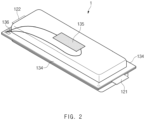
- FIG. 2 is a perspective view of the secondary battery 1 according to an embodiment of the present invention.
- a punching part 136 may punch the battery case 13 to allow a gas generated in the battery case 13 to be quickly discharged, thereby preventing explosion and ensuring stability.
- the secondary battery 1 includes: an electrode assembly 10 formed by alternately stacking an electrode and a separator; a battery case 13 that accommodates the electrode assembly 10 therein; a piezoelectric element 135 disposed outside a cup part 133 accommodating the electrode assembly 10 in the battery case 13 to receive a pressure when the battery case 13 is expanded in volume, thereby supplying the power to the outside; and a punching part 136 which has sharp one end 1361 and of which the one end 1361 extends toward the battery case 13 to punch the battery case 13 when the power is applied from the piezoelectric element 135.
- the electrode assembly 10 is formed by alternately stacking the electrode and the separator. First, slurry in which an electrode active material, a binder, and a plasticizer are mixed with each other is applied to a cathode collector and an anode collector to manufacture a cathode and an anode. Thereafter, the cathode and the anode are respectively stacked on both sides of the separator to form an electrode assembly 10 having a predetermined shape. Then, the electrode assembly is inserted into the battery case 13, an electrolyte is injected into the battery case 13, and a sealing process is performed.
- the electrode assembly 10 includes two types of electrodes, such as the cathode and the anode, and the separator interposed between the electrodes to insulate the electrodes from each other.
- the electrode assembly 10 may be a stack type, a jelly roll type, a stacked and folding type, or the like.
- Each of the two types of electrodes, i.e., the cathode and the anode has a structure in which active material slurry is applied to the electrode collector having a metal foil or metal mesh shape.
- the slurry may be usually formed by agitating a granular active material, an auxiliary conductor, a binder, and a plasticizer with a solvent added. The solvent may be removed in the subsequent process.
- the electrode assembly 10 includes an electrode tab 11.
- the electrode tabs 11 are respectively connected to the cathode and the anode of the electrode assembly 10 to protrude outward from one side of the electrode assembly 10, thereby providing a path, through which electrons move, between the inside and outside of the electrode assembly 10.
- a collector of the electrode assembly 10 is constituted by a portion coated with an electrode active material and a distal end, on which the electrode active material is not applied, i.e., a non-coating portion.
- the electrode tab 11 may be formed by cutting the non-coating portion or by connecting a separate conductive member to the non-coating portion through ultrasonic welding.
- the electrode tabs 11 may protrude from one side of the electrode assembly 10 in directions different from each other, but the present invention is not limited thereto.
- the electrode tabs 11 may protrude in the same direction.
- the electrode lead 12 is connected to the electrode tab 11 through spot welding. Also, a portion of the electrode lead 12 is surrounded by an insulation part 14.
- the insulation part 14 may be disposed to be limited within a sealing part 134, at which an upper case 131 and a lower case 132 of the battery case 13 are thermally fused, so that the electrode lead 12 is bonded to the battery case 13. Also, electricity generated from the electrode assembly 10 may be prevented from flowing to the battery case 13 through the electrode lead 12, and the sealing of the battery case 13 may be maintained.
- the insulation part 14 may be made of a nonconductor having non-conductivity, which is not electrically conductive.
- the present invention is not limited thereto.
- various members may be used as the insulation part 14 as long as the members are capable of insulating the electrode lead 12.
- the electrode lead 12 includes a cathode lead 121 having one end connected to a cathode tab 111 to extend in a direction in which the cathode tab 111 protrudes and an anode lead 122 having one end connected to an anode tab 112 to extend in a direction in which the anode tab 112 protrudes.
- the electrode lead 12 includes a cathode lead 121 having one end connected to a cathode tab 111 to extend in a direction in which the cathode tab 111 protrudes and an anode lead 122 having one end connected to an anode tab 112 to extend in a direction in which the anode tab 112 protrudes.
- all of the other ends of the cathode lead 121 and the anode lead 122 protrude to the outside of the battery case 13.
- electricity generated in the electrode assembly 10 may be supplied to the outside.
- each of the cathode tab 111 and the anode tab 112 is formed to protrude in various directions
- the cathode lead 121 and the anode lead 122 may be made of materials different from each other. That is, the cathode lead 121 may be made of the same material as the cathode collector, i.e., an aluminum (Al) material, and the anode lead 122 may be made of the same material as the anode collector, i.e., a copper (Cu) material or a copper material coated with nickel (Ni). Also, a portion of the electrode lead 12, which protrudes to the outside of the battery case 13, may be provided as a terminal part and electrically connected to an external terminal.
- Al aluminum
- the anode lead 122 may be made of the same material as the anode collector, i.e., a copper (Cu) material or a copper material coated with nickel (Ni).
- a portion of the electrode lead 12, which protrudes to the outside of the battery case 13 may be provided as a terminal part and electrically connected to an external terminal.
- the battery case 13 is a pouch made of a flexible material.
- the battery case 13 accommodates the electrode assembly 10 so that a portion of the electrode lead 12, i.e., the terminal part is exposed and then is sealed.
- the battery case 13 includes the upper case 131 and the lower case 132.
- An accommodation space 1331 in which a cup part 133 is formed to accommodate the electrode assembly 10 may be provided in the lower case 132, and upper case 131 may cover an upper side of the accommodation space 1331 so that the electrode assembly 10 is not separated to the outside of the battery case 13.
- the cup part 133 having the accommodation space 1331 may be formed in the upper case 131 to accommodate the electrode assembly 10 in the upper portion.
- one side of the upper case 131 and one side of the lower case 132 may be connected to each other.
- the present invention is not limited thereto.
- the upper case 131 and the lower case 132 may be separately manufactured to be separated from each other.
- the piezoelectric element 135 is disposed outside the cup part 133 to receive the pressure when the battery case 13 is expanded in volume, thereby supplying the power to the outside. Also, the punching part 136 has the sharp one end 1361. When the power is applied from the piezoelectric element 135, the one end 1361 extends to the battery case 13 to punch the battery case 13.
- the piezoelectric element 135 and punching part 136 will be described below in detail.
- the electrode assembly 10 When an electrode lead 12 is connected to the electrode tab 11 of the electrode assembly 10, and the insulation part 14 is provided on a portion of the electrode lead 12, the electrode assembly 10 may be accommodated in the accommodation space 1331 provided in the cup part 133 of the lower case 132, and the upper case 131 may cover an upper portion of the accommodation space. Also, the electrolyte is injected, and the sealing part 134 formed on edges of the upper case 131 and the lower case 132 is sealed. The electrolyte may move lithium ions generated by electrochemical reaction of the electrode during charging and discharging of the secondary battery 1.
- the electrolyte may include a non-aqueous organic electrolyte that is a mixture of a lithium salt and a high-purity organic solvent or a polymer using a polymer electrolyte.
- a non-aqueous organic electrolyte that is a mixture of a lithium salt and a high-purity organic solvent or a polymer using a polymer electrolyte.
- the pouch type secondary battery 1 may be manufactured through the above-described method.
- FIG. 3 is plan view of the secondary battery 1 according to an embodiment of the present invention
- FIG. 4 is an enlarged cross-sectional view of the secondary battery 1 according to an embodiment of the present invention.
- the secondary battery 1 includes the piezoelectric element 135 and the punching part 136.
- the piezoelectric element 135 is an element that generates a voltage when physical external force such as a pressure, stress, or the like is applied, and on the contrary, is deformed when a voltage is applied.
- Typical piezoelectric elements 135 include barium titanate, rochelle salt, and the like.
- the piezoelectric element 135 is disposed outside the cup part 133 of the battery case 13. Therefore, when a gas is generated in the battery case 13 to expand a volume of the battery case 13, a pressure is applied. Accordingly, a voltage is generated in the piezoelectric element 135 to supply the power to the outside.
- the piezoelectric element 135 may be directly attached to an outer surface of the cup part 133. As a result, the piezoelectric element may sensitively react to the expansion of the battery case 13. That is, even if the volume of the battery case 13 is slightly expanded, the voltage may be immediately generated to be supplied to the outside.
- the piezoelectric element 135 may have a shape corresponding to that of the cup part 133. For example, if the cup part 133 has a rectangular shape, the piezoelectric element 135 may also have a rectangular shape. If the cup part 133 has a circular shape, the piezoelectric element 135 may also have a circular shape. As a result, when the cup part 133 is deformed, the piezoelectric element 135 may receive a pressure in proportion to a degree of the deformation of the cup part 133.
- the piezoelectric element 135 is preferably attached to a substantially central portion of the cup part 133. If a gas is generated inside the battery case 13, the cup part 133 having the greatest flexibility is deformed the largest. Here, the piezoelectric element 135 is attached to the central portion of the cup part 133. When the cup part 133 is deformed, the piezoelectric element 135 may uniformly receive the pressure on the whole.
- the punching part 136 may have a thin and long wire shape. When the power is applied to the piezoelectric element 135, the punching part 136 may be deformed to punch the battery case 13.
- the punching part 136 may be made of an electroactive polymer (EAP).
- EAP electroactive polymer
- the electroactive polymer is a polymer that is capable of being deformed by expansion, contraction, bending, etc., by electrical stimulation.
- Representative electroactive polymers include ferroelectric polymers and dielectric elastomers.
- PVDF piezoelectric polyvinylidene fluoride
- the punching part 136 may be formed in close contact with the sealing part 134 of the battery case 13. As a result, the punching part 136 may be prevented from being damaged by external friction without largely changing a size and shape of the secondary battery 1. If a length of the punching part 136 is formed to some extent, as illustrated in FIG. 3 , the punching part 136 may be in close contact with a portion of the sealing part 134 formed along a peripheral edge in the battery case 13.
- the present invention is not limited thereto, and the punching part 136 may be formed in the battery case 13 in various manners, for example, formed along the outer surface of the cup part 133 accommodating the electrode assembly 10 in the battery case 13.
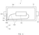
- FIG. 5 is a plan view of the secondary battery 1 when one end 1361 of the punching part 136 of the secondary battery 1 extends according to an embodiment of the present invention
- FIG. 6 is an enlarged cross-sectional view of the secondary battery 1 when the one end 1361 of the punching part 136 of the secondary battery 1 extends according to an embodiment of the present invention.
- the piezoelectric element 135 When the piezoelectric element 135 receives a pressure, a voltage is generated to supply power to the outside. That is, when a gas is generated in the battery case 13 to expand a volume of the battery case 13, the piezoelectric element 135 may receive the pressure to supply power to the outside.
- the punching part 136 has a sharp one end 1361 and is changed in shape when power is applied from the piezoelectric element 135. In particular, as illustrated in FIG. 5 , the one end 1361 of the punching part 136 extends toward the battery case 13 to punch the battery case 13.
- the punching part 136 may preferably punch the cup part 133 in the battery case 13. As a result, the inside and the outside of the battery case 13 is connected to each other, and thus, the gas generated in the battery case 13 may be quickly discharged to the outside to prevent the explosion and secure the stability.
- the one end 1361 of the punching part 136 is not disposed near a vertex of the cup part 133 but is disposed at a center of an edge of the cup part 133 as illustrated in FIG. 5 .
- the central portion of the edge is weaker than the vicinity of the vertex of the cup part 133, when the one end 1361 of the punching part 136 is extended, as illustrated in FIG. 6 , the cup part 133 may be easily punched.
- the other end 1362 of the punching part 136 is not disposed at the central portion of the edge of the cup part 133 but disposed near the vertex of the cup part 133, as illustrated in FIG. 5 .
- a conductive wire 1351 connected to the piezoelectric element 135 is connected to the other end 1362 of the punching part 136.
- FIG. 7 is an assembly view of a battery module 2 according to another embodiment of the present invention.
- the piezoelectric element 135 is directly attached to the outer surface of the cup part 133 of the battery case 13, and the punching part 136 is formed in close contact with the sealing part 134 of the battery case 13.
- the piezoelectric element 135 may sensitively react to the expansion of the volume of the battery case 13, and the punching part 136 may be prevented from being damaged by external friction without largely changing a size and shape of the secondary battery 1.
- a piezoelectric element 135a and a punching part 136a may not be formed in a battery case 13 of the secondary battery 1a, but be formed in the housing 20 of the battery module 2.
- the battery module 2 includes: a secondary battery including an electrode assembly 10 formed by alternately stacking an electrode and a separator, a battery case 13 that accommodates the electrode assembly 10 therein, a piezoelectric element 135a disposed outside a cup part 133 accommodating the electrode assembly 10 in the battery case 13 to receive a pressure when the battery case 13 is expanded in volume, thereby supplying the power to the outside, and a punching part 136a which has a sharp one end 1361a and of which the one end 1361a extends toward the battery case 13 to punch the battery case 13 when the power is applied from the piezoelectric element 135a; and a housing 20 accommodating the secondary battery 1 therein.
- the housing 20 accommodates the secondary battery 1a therein, and as illustrated in FIG. 7 , upper and lower housings 20 are coupled to each other at both sides of the secondary battery 1a to accommodate the secondary battery 1a.
- the housing 20 may accommodate only one secondary battery 1a therein, but is not limited thereto.
- the housing 20 may accommodate a plurality of secondary batteries 1a.
- the piezoelectric element 135a and the punching part 136a are formed in the housing 200 of the battery module 2.
- the piezoelectric element 135a is disposed outside the cup part 133 of the battery case 13, but is attached to an inner surface of the housing 20 without being directly attached to an outer surface of the cup part 133.
- the inner surface of the housing 20 and the cup part 133 of the battery case 13 are disposed very close to each other, when a gas is generated inside the battery case 13 to expand a volume of the battery case 13, the piezoelectric element 136a immediately supplies power to the outside.
- the punching part 136a is formed in close contact with an inner edge of the housing 20. Also, the punching part 136a may have a thin and long wire shape. When the power is applied to the piezoelectric element 135a, the punching part 136a may be deformed to punch the battery case 13.
- the punching part 136a may be made of an electroactive polymer (EAP).
- FIG. 8 is an assembly view of the battery module 2 when the one end 1361a of the punching part 136a of the battery module 2 extends according to another embodiment of the present invention.
- the piezoelectric element 135a may receive the pressure to supply power to the outside. Also, since the one end 1361a of the punching part 136a is sharply formed, when the power is applied from the piezoelectric element 135a, as illustrated in FIG. 8 , the one end 1361a of the punching part 136a extends toward the battery case 13 to punch the battery case 13.
- the punching part 136a punches the cup part 133 of the battery case 13. Also, the one end 1361a of the punching part 136a is disposed at a center of the edge of the cup part 133. As a result, the cup part 133 may be easily punched when the one end 1361a of the punching part 136a extends.
Landscapes
- Chemical & Material Sciences (AREA)
- Chemical Kinetics & Catalysis (AREA)
- Electrochemistry (AREA)
- General Chemical & Material Sciences (AREA)
- Sealing Battery Cases Or Jackets (AREA)
- Secondary Cells (AREA)
- Battery Mounting, Suspending (AREA)
- Gas Exhaust Devices For Batteries (AREA)
Applications Claiming Priority (2)
| Application Number | Priority Date | Filing Date | Title |
|---|---|---|---|
| KR1020190017331A KR102379765B1 (ko) | 2019-02-14 | 2019-02-14 | 이차 전지 및 전지 모듈 |
| PCT/KR2019/017190 WO2020166803A1 (ko) | 2019-02-14 | 2019-12-06 | 이차 전지 및 전지 모듈 |
Publications (3)
| Publication Number | Publication Date |
|---|---|
| EP3754749A1 EP3754749A1 (en) | 2020-12-23 |
| EP3754749A4 EP3754749A4 (en) | 2021-06-23 |
| EP3754749B1 true EP3754749B1 (en) | 2023-11-15 |
Family
ID=72043922
Family Applications (1)
| Application Number | Title | Priority Date | Filing Date |
|---|---|---|---|
| EP19915222.4A Active EP3754749B1 (en) | 2019-02-14 | 2019-12-06 | Secondary battery and battery module |
Country Status (9)
| Country | Link |
|---|---|
| US (1) | US11616269B2 (pl) |
| EP (1) | EP3754749B1 (pl) |
| JP (1) | JP7098189B2 (pl) |
| KR (1) | KR102379765B1 (pl) |
| CN (1) | CN111837255B (pl) |
| ES (1) | ES2966783T3 (pl) |
| HU (1) | HUE064926T2 (pl) |
| PL (1) | PL3754749T3 (pl) |
| WO (1) | WO2020166803A1 (pl) |
Families Citing this family (3)
| Publication number | Priority date | Publication date | Assignee | Title |
|---|---|---|---|---|
| JP7585943B2 (ja) * | 2021-03-31 | 2024-11-19 | トヨタ自動車株式会社 | 蓄電装置 |
| KR102827557B1 (ko) * | 2022-12-20 | 2025-07-01 | 주식회사 성우하이텍 | 배터리 모듈 조립체 및 이를 포함하는 전기 차량 |
| CN116130857B (zh) * | 2023-04-13 | 2023-08-29 | 宁德时代新能源科技股份有限公司 | 用电装置、电池及其控制方法 |
Family Cites Families (27)
| Publication number | Priority date | Publication date | Assignee | Title |
|---|---|---|---|---|
| KR20000051638A (ko) | 1999-01-25 | 2000-08-16 | 김순택 | 이차전지 |
| JP4686833B2 (ja) * | 2000-09-19 | 2011-05-25 | 株式会社Gsユアサ | 電池パック |
| US7233097B2 (en) * | 2001-05-22 | 2007-06-19 | Sri International | Rolled electroactive polymers |
| US20060251965A1 (en) | 2003-07-31 | 2006-11-09 | Mori Nagayama | Secondary cell electrode and fabrication method, and secondary cell, complex cell, and vehicle |
| CN1870930A (zh) | 2003-08-20 | 2006-11-29 | 新引导系统公司 | 活化聚合物关节连接的器械及插入方法 |
| US7541715B2 (en) | 2004-06-14 | 2009-06-02 | Massachusetts Institute Of Technology | Electrochemical methods, devices, and structures |
| JP5002894B2 (ja) | 2004-12-27 | 2012-08-15 | 日産自動車株式会社 | 二次電池 |
| KR100889244B1 (ko) | 2005-04-20 | 2009-03-17 | 주식회사 엘지화학 | 압전 센서가 내장된 이차전지 모듈 |
| KR100878702B1 (ko) | 2005-11-30 | 2009-01-14 | 주식회사 엘지화학 | 이차전지용 안전장치 및 그것을 포함하는 전지팩 |
| JP5147206B2 (ja) * | 2006-08-11 | 2013-02-20 | 三洋電機株式会社 | 非水電解質二次電池 |
| KR101093937B1 (ko) | 2009-11-26 | 2011-12-13 | 삼성에스디아이 주식회사 | 이차 전지 및 그를 이용한 전지 팩 |
| KR101097101B1 (ko) | 2009-12-29 | 2011-12-22 | 주식회사 루트제이드 | 폭발방지수단을 구비하는 이차전지 |
| WO2011132723A1 (ja) | 2010-04-24 | 2011-10-27 | Fdk株式会社 | 内圧解放機構付きの蓄電デバイス、蓄電モジュール |
| JP5455768B2 (ja) * | 2010-04-24 | 2014-03-26 | Fdk株式会社 | 蓄電デバイス |
| KR101136274B1 (ko) | 2010-07-01 | 2012-04-19 | 삼성에스디아이 주식회사 | 이차 전지 |
| KR101330615B1 (ko) | 2011-04-26 | 2013-11-18 | 로베르트 보쉬 게엠베하 | 이차 전지 |
| KR101292618B1 (ko) | 2011-08-17 | 2013-08-02 | 에스케이이노베이션 주식회사 | 이차전지 |
| KR101313971B1 (ko) | 2011-12-07 | 2013-10-01 | 세방전지(주) | 천공 스위치를 가지는 리튬 이차 전지 |
| JP2014154292A (ja) | 2013-02-06 | 2014-08-25 | Toyota Motor Corp | 二次電池 |
| DE102014201162A1 (de) | 2014-01-23 | 2015-07-23 | Robert Bosch Gmbh | Batteriezelle, Batteriepack und Transportbehälter |
| KR20160021347A (ko) * | 2014-08-14 | 2016-02-25 | 에스케이이노베이션 주식회사 | 파우치형 이차전지의 벤팅장치 및 이를 포함하는 파우치형 이차전지 |
| EP3032597B1 (en) * | 2014-12-09 | 2019-02-27 | LG Display Co., Ltd. | Transformable device and method of manufacturing the same |
| KR20170050926A (ko) * | 2015-11-02 | 2017-05-11 | 주식회사 엘지화학 | 가스 배출부의 변위를 감지하여 배터리 셀 스웰링을 방지하는 이차 전지, 이차 전지 충전 시스템 및 이차 전지 제조 방법 |
| KR20170084789A (ko) * | 2016-01-13 | 2017-07-21 | 주식회사 엘지화학 | 전지셀용 안전부재 및 이를 포함하는 전지팩 |
| KR102245619B1 (ko) | 2016-08-31 | 2021-04-27 | 삼성에스디아이 주식회사 | 배터리 팩 |
| US10431816B2 (en) * | 2017-07-17 | 2019-10-01 | GM Global Technology Operations LLC | Battery cell with increased tab area and method and apparatus for manufacturing same |
| CN207398300U (zh) | 2017-10-25 | 2018-05-22 | 东莞新能德科技有限公司 | 电池模组和电子产品 |
-
2019
- 2019-02-14 KR KR1020190017331A patent/KR102379765B1/ko active Active
- 2019-12-06 PL PL19915222.4T patent/PL3754749T3/pl unknown
- 2019-12-06 ES ES19915222T patent/ES2966783T3/es active Active
- 2019-12-06 EP EP19915222.4A patent/EP3754749B1/en active Active
- 2019-12-06 US US16/981,776 patent/US11616269B2/en active Active
- 2019-12-06 JP JP2020549692A patent/JP7098189B2/ja active Active
- 2019-12-06 CN CN201980017199.XA patent/CN111837255B/zh active Active
- 2019-12-06 HU HUE19915222A patent/HUE064926T2/hu unknown
- 2019-12-06 WO PCT/KR2019/017190 patent/WO2020166803A1/ko not_active Ceased
Also Published As
| Publication number | Publication date |
|---|---|
| EP3754749A4 (en) | 2021-06-23 |
| US11616269B2 (en) | 2023-03-28 |
| US20210013473A1 (en) | 2021-01-14 |
| ES2966783T3 (es) | 2024-04-24 |
| PL3754749T3 (pl) | 2024-03-11 |
| CN111837255B (zh) | 2022-09-02 |
| HUE064926T2 (hu) | 2024-05-28 |
| CN111837255A (zh) | 2020-10-27 |
| KR102379765B1 (ko) | 2022-03-29 |
| EP3754749A1 (en) | 2020-12-23 |
| JP2021516436A (ja) | 2021-07-01 |
| WO2020166803A1 (ko) | 2020-08-20 |
| JP7098189B2 (ja) | 2022-07-11 |
| KR20200099392A (ko) | 2020-08-24 |
Similar Documents
| Publication | Publication Date | Title |
|---|---|---|
| EP2557609B1 (en) | Rechargeable battery and method for fabricating the same | |
| EP4057438A1 (en) | Electrode tab bending apparatus and method | |
| EP3916830A1 (en) | Secondary battery battery case and pouch-type secondary battery | |
| KR102742761B1 (ko) | 전극 조립체 및 이차 전지 | |
| EP4350848B1 (en) | Venting device | |
| US11387516B2 (en) | Battery module | |
| US20230079811A1 (en) | Pouch-Type Battery Cell Including Venting Member and Battery Pack Including the Same | |
| EP2325925A1 (en) | Electrode assembly and rechargeable battery using the same | |
| EP3518313B1 (en) | Secondary battery | |
| EP3544089A1 (en) | Pouch-type secondary battery | |
| CN114651350B (zh) | 电极组件及其制造方法 | |
| US12476298B2 (en) | Pouch type battery case and pouch type secondary battery | |
| EP3754749B1 (en) | Secondary battery and battery module | |
| US11394093B2 (en) | Secondary battery and battery module | |
| EP2922116B1 (en) | Secondary battery | |
| US8481193B2 (en) | Battery module and method of manufacturing the same | |
| US12555853B2 (en) | Secondary battery and battery module | |
| US20260094955A1 (en) | Secondary battery and battery module |
Legal Events
| Date | Code | Title | Description |
|---|---|---|---|
| STAA | Information on the status of an ep patent application or granted ep patent |
Free format text: STATUS: THE INTERNATIONAL PUBLICATION HAS BEEN MADE |
|
| PUAI | Public reference made under article 153(3) epc to a published international application that has entered the european phase |
Free format text: ORIGINAL CODE: 0009012 |
|
| STAA | Information on the status of an ep patent application or granted ep patent |
Free format text: STATUS: REQUEST FOR EXAMINATION WAS MADE |
|
| 17P | Request for examination filed |
Effective date: 20200914 |
|
| AK | Designated contracting states |
Kind code of ref document: A1 Designated state(s): AL AT BE BG CH CY CZ DE DK EE ES FI FR GB GR HR HU IE IS IT LI LT LU LV MC MK MT NL NO PL PT RO RS SE SI SK SM TR |
|
| AX | Request for extension of the european patent |
Extension state: BA ME |
|
| REG | Reference to a national code |
Ref country code: DE Ref legal event code: R079 Free format text: PREVIOUS MAIN CLASS: H01M0002120000 Ref country code: DE Ref legal event code: R079 Ref document number: 602019041712 Country of ref document: DE Free format text: PREVIOUS MAIN CLASS: H01M0002120000 Ipc: H01M0050105000 |
|
| A4 | Supplementary search report drawn up and despatched |
Effective date: 20210521 |
|
| RIC1 | Information provided on ipc code assigned before grant |
Ipc: H01M 50/105 20210101AFI20210517BHEP Ipc: H01M 50/342 20210101ALI20210517BHEP Ipc: H01M 50/572 20210101ALI20210517BHEP |
|
| RAP1 | Party data changed (applicant data changed or rights of an application transferred) |
Owner name: LG ENERGY SOLUTION LTD. |
|
| RAP3 | Party data changed (applicant data changed or rights of an application transferred) |
Owner name: LG ENERGY SOLUTION, LTD. |
|
| DAV | Request for validation of the european patent (deleted) | ||
| DAX | Request for extension of the european patent (deleted) | ||
| STAA | Information on the status of an ep patent application or granted ep patent |
Free format text: STATUS: EXAMINATION IS IN PROGRESS |
|
| 17Q | First examination report despatched |
Effective date: 20230503 |
|
| GRAP | Despatch of communication of intention to grant a patent |
Free format text: ORIGINAL CODE: EPIDOSNIGR1 |
|
| STAA | Information on the status of an ep patent application or granted ep patent |
Free format text: STATUS: GRANT OF PATENT IS INTENDED |
|
| INTG | Intention to grant announced |
Effective date: 20230629 |
|
| P01 | Opt-out of the competence of the unified patent court (upc) registered |
Effective date: 20230706 |
|
| GRAS | Grant fee paid |
Free format text: ORIGINAL CODE: EPIDOSNIGR3 |
|
| GRAA | (expected) grant |
Free format text: ORIGINAL CODE: 0009210 |
|
| STAA | Information on the status of an ep patent application or granted ep patent |
Free format text: STATUS: THE PATENT HAS BEEN GRANTED |
|
| AK | Designated contracting states |
Kind code of ref document: B1 Designated state(s): AL AT BE BG CH CY CZ DE DK EE ES FI FR GB GR HR HU IE IS IT LI LT LU LV MC MK MT NL NO PL PT RO RS SE SI SK SM TR |
|
| REG | Reference to a national code |
Ref country code: CH Ref legal event code: EP Ref country code: GB Ref legal event code: FG4D |
|
| REG | Reference to a national code |
Ref country code: DE Ref legal event code: R096 Ref document number: 602019041712 Country of ref document: DE |
|
| REG | Reference to a national code |
Ref country code: IE Ref legal event code: FG4D |
|
| REG | Reference to a national code |
Ref country code: SE Ref legal event code: TRGR |
|
| REG | Reference to a national code |
Ref country code: LT Ref legal event code: MG9D |
|
| REG | Reference to a national code |
Ref country code: NL Ref legal event code: MP Effective date: 20231115 |
|
| PG25 | Lapsed in a contracting state [announced via postgrant information from national office to epo] |
Ref country code: GR Free format text: LAPSE BECAUSE OF FAILURE TO SUBMIT A TRANSLATION OF THE DESCRIPTION OR TO PAY THE FEE WITHIN THE PRESCRIBED TIME-LIMIT Effective date: 20240216 |
|
| PG25 | Lapsed in a contracting state [announced via postgrant information from national office to epo] |
Ref country code: IS Free format text: LAPSE BECAUSE OF FAILURE TO SUBMIT A TRANSLATION OF THE DESCRIPTION OR TO PAY THE FEE WITHIN THE PRESCRIBED TIME-LIMIT Effective date: 20240315 |
|
| PG25 | Lapsed in a contracting state [announced via postgrant information from national office to epo] |
Ref country code: LT Free format text: LAPSE BECAUSE OF FAILURE TO SUBMIT A TRANSLATION OF THE DESCRIPTION OR TO PAY THE FEE WITHIN THE PRESCRIBED TIME-LIMIT Effective date: 20231115 |
|
| REG | Reference to a national code |
Ref country code: AT Ref legal event code: MK05 Ref document number: 1632620 Country of ref document: AT Kind code of ref document: T Effective date: 20231115 |
|
| PG25 | Lapsed in a contracting state [announced via postgrant information from national office to epo] |
Ref country code: NL Free format text: LAPSE BECAUSE OF FAILURE TO SUBMIT A TRANSLATION OF THE DESCRIPTION OR TO PAY THE FEE WITHIN THE PRESCRIBED TIME-LIMIT Effective date: 20231115 |
|
| PG25 | Lapsed in a contracting state [announced via postgrant information from national office to epo] |
Ref country code: AT Free format text: LAPSE BECAUSE OF FAILURE TO SUBMIT A TRANSLATION OF THE DESCRIPTION OR TO PAY THE FEE WITHIN THE PRESCRIBED TIME-LIMIT Effective date: 20231115 |
|
| REG | Reference to a national code |
Ref country code: ES Ref legal event code: FG2A Ref document number: 2966783 Country of ref document: ES Kind code of ref document: T3 Effective date: 20240424 |
|
| PG25 | Lapsed in a contracting state [announced via postgrant information from national office to epo] |
Ref country code: NL Free format text: LAPSE BECAUSE OF FAILURE TO SUBMIT A TRANSLATION OF THE DESCRIPTION OR TO PAY THE FEE WITHIN THE PRESCRIBED TIME-LIMIT Effective date: 20231115 Ref country code: LT Free format text: LAPSE BECAUSE OF FAILURE TO SUBMIT A TRANSLATION OF THE DESCRIPTION OR TO PAY THE FEE WITHIN THE PRESCRIBED TIME-LIMIT Effective date: 20231115 Ref country code: IS Free format text: LAPSE BECAUSE OF FAILURE TO SUBMIT A TRANSLATION OF THE DESCRIPTION OR TO PAY THE FEE WITHIN THE PRESCRIBED TIME-LIMIT Effective date: 20240315 Ref country code: GR Free format text: LAPSE BECAUSE OF FAILURE TO SUBMIT A TRANSLATION OF THE DESCRIPTION OR TO PAY THE FEE WITHIN THE PRESCRIBED TIME-LIMIT Effective date: 20240216 Ref country code: BG Free format text: LAPSE BECAUSE OF FAILURE TO SUBMIT A TRANSLATION OF THE DESCRIPTION OR TO PAY THE FEE WITHIN THE PRESCRIBED TIME-LIMIT Effective date: 20240215 Ref country code: AT Free format text: LAPSE BECAUSE OF FAILURE TO SUBMIT A TRANSLATION OF THE DESCRIPTION OR TO PAY THE FEE WITHIN THE PRESCRIBED TIME-LIMIT Effective date: 20231115 Ref country code: PT Free format text: LAPSE BECAUSE OF FAILURE TO SUBMIT A TRANSLATION OF THE DESCRIPTION OR TO PAY THE FEE WITHIN THE PRESCRIBED TIME-LIMIT Effective date: 20240315 |
|
| REG | Reference to a national code |
Ref country code: HU Ref legal event code: AG4A Ref document number: E064926 Country of ref document: HU |
|
| PG25 | Lapsed in a contracting state [announced via postgrant information from national office to epo] |
Ref country code: RS Free format text: LAPSE BECAUSE OF FAILURE TO SUBMIT A TRANSLATION OF THE DESCRIPTION OR TO PAY THE FEE WITHIN THE PRESCRIBED TIME-LIMIT Effective date: 20231115 Ref country code: NO Free format text: LAPSE BECAUSE OF FAILURE TO SUBMIT A TRANSLATION OF THE DESCRIPTION OR TO PAY THE FEE WITHIN THE PRESCRIBED TIME-LIMIT Effective date: 20240215 Ref country code: LV Free format text: LAPSE BECAUSE OF FAILURE TO SUBMIT A TRANSLATION OF THE DESCRIPTION OR TO PAY THE FEE WITHIN THE PRESCRIBED TIME-LIMIT Effective date: 20231115 Ref country code: HR Free format text: LAPSE BECAUSE OF FAILURE TO SUBMIT A TRANSLATION OF THE DESCRIPTION OR TO PAY THE FEE WITHIN THE PRESCRIBED TIME-LIMIT Effective date: 20231115 |
|
| PG25 | Lapsed in a contracting state [announced via postgrant information from national office to epo] |
Ref country code: DK Free format text: LAPSE BECAUSE OF FAILURE TO SUBMIT A TRANSLATION OF THE DESCRIPTION OR TO PAY THE FEE WITHIN THE PRESCRIBED TIME-LIMIT Effective date: 20231115 |
|
| PG25 | Lapsed in a contracting state [announced via postgrant information from national office to epo] |
Ref country code: CZ Free format text: LAPSE BECAUSE OF FAILURE TO SUBMIT A TRANSLATION OF THE DESCRIPTION OR TO PAY THE FEE WITHIN THE PRESCRIBED TIME-LIMIT Effective date: 20231115 |
|
| PG25 | Lapsed in a contracting state [announced via postgrant information from national office to epo] |
Ref country code: SK Free format text: LAPSE BECAUSE OF FAILURE TO SUBMIT A TRANSLATION OF THE DESCRIPTION OR TO PAY THE FEE WITHIN THE PRESCRIBED TIME-LIMIT Effective date: 20231115 |
|
| PG25 | Lapsed in a contracting state [announced via postgrant information from national office to epo] |
Ref country code: SM Free format text: LAPSE BECAUSE OF FAILURE TO SUBMIT A TRANSLATION OF THE DESCRIPTION OR TO PAY THE FEE WITHIN THE PRESCRIBED TIME-LIMIT Effective date: 20231115 Ref country code: SK Free format text: LAPSE BECAUSE OF FAILURE TO SUBMIT A TRANSLATION OF THE DESCRIPTION OR TO PAY THE FEE WITHIN THE PRESCRIBED TIME-LIMIT Effective date: 20231115 Ref country code: RO Free format text: LAPSE BECAUSE OF FAILURE TO SUBMIT A TRANSLATION OF THE DESCRIPTION OR TO PAY THE FEE WITHIN THE PRESCRIBED TIME-LIMIT Effective date: 20231115 Ref country code: IT Free format text: LAPSE BECAUSE OF FAILURE TO SUBMIT A TRANSLATION OF THE DESCRIPTION OR TO PAY THE FEE WITHIN THE PRESCRIBED TIME-LIMIT Effective date: 20231115 Ref country code: EE Free format text: LAPSE BECAUSE OF FAILURE TO SUBMIT A TRANSLATION OF THE DESCRIPTION OR TO PAY THE FEE WITHIN THE PRESCRIBED TIME-LIMIT Effective date: 20231115 Ref country code: DK Free format text: LAPSE BECAUSE OF FAILURE TO SUBMIT A TRANSLATION OF THE DESCRIPTION OR TO PAY THE FEE WITHIN THE PRESCRIBED TIME-LIMIT Effective date: 20231115 Ref country code: CZ Free format text: LAPSE BECAUSE OF FAILURE TO SUBMIT A TRANSLATION OF THE DESCRIPTION OR TO PAY THE FEE WITHIN THE PRESCRIBED TIME-LIMIT Effective date: 20231115 |
|
| REG | Reference to a national code |
Ref country code: CH Ref legal event code: PL |
|
| REG | Reference to a national code |
Ref country code: DE Ref legal event code: R097 Ref document number: 602019041712 Country of ref document: DE |
|
| PG25 | Lapsed in a contracting state [announced via postgrant information from national office to epo] |
Ref country code: LU Free format text: LAPSE BECAUSE OF NON-PAYMENT OF DUE FEES Effective date: 20231206 |
|
| PG25 | Lapsed in a contracting state [announced via postgrant information from national office to epo] |
Ref country code: MC Free format text: LAPSE BECAUSE OF FAILURE TO SUBMIT A TRANSLATION OF THE DESCRIPTION OR TO PAY THE FEE WITHIN THE PRESCRIBED TIME-LIMIT Effective date: 20231115 |
|
| REG | Reference to a national code |
Ref country code: BE Ref legal event code: MM Effective date: 20231231 |
|
| PG25 | Lapsed in a contracting state [announced via postgrant information from national office to epo] |
Ref country code: MC Free format text: LAPSE BECAUSE OF FAILURE TO SUBMIT A TRANSLATION OF THE DESCRIPTION OR TO PAY THE FEE WITHIN THE PRESCRIBED TIME-LIMIT Effective date: 20231115 Ref country code: LU Free format text: LAPSE BECAUSE OF NON-PAYMENT OF DUE FEES Effective date: 20231206 |
|
| PLBE | No opposition filed within time limit |
Free format text: ORIGINAL CODE: 0009261 |
|
| STAA | Information on the status of an ep patent application or granted ep patent |
Free format text: STATUS: NO OPPOSITION FILED WITHIN TIME LIMIT |
|
| REG | Reference to a national code |
Ref country code: IE Ref legal event code: MM4A |
|
| PG25 | Lapsed in a contracting state [announced via postgrant information from national office to epo] |
Ref country code: IE Free format text: LAPSE BECAUSE OF NON-PAYMENT OF DUE FEES Effective date: 20231206 |
|
| PG25 | Lapsed in a contracting state [announced via postgrant information from national office to epo] |
Ref country code: BE Free format text: LAPSE BECAUSE OF NON-PAYMENT OF DUE FEES Effective date: 20231231 |
|
| PG25 | Lapsed in a contracting state [announced via postgrant information from national office to epo] |
Ref country code: CH Free format text: LAPSE BECAUSE OF NON-PAYMENT OF DUE FEES Effective date: 20231231 |
|
| 26N | No opposition filed |
Effective date: 20240819 |
|
| PG25 | Lapsed in a contracting state [announced via postgrant information from national office to epo] |
Ref country code: SI Free format text: LAPSE BECAUSE OF FAILURE TO SUBMIT A TRANSLATION OF THE DESCRIPTION OR TO PAY THE FEE WITHIN THE PRESCRIBED TIME-LIMIT Effective date: 20231115 |
|
| PG25 | Lapsed in a contracting state [announced via postgrant information from national office to epo] |
Ref country code: SI Free format text: LAPSE BECAUSE OF FAILURE TO SUBMIT A TRANSLATION OF THE DESCRIPTION OR TO PAY THE FEE WITHIN THE PRESCRIBED TIME-LIMIT Effective date: 20231115 Ref country code: IE Free format text: LAPSE BECAUSE OF NON-PAYMENT OF DUE FEES Effective date: 20231206 Ref country code: CH Free format text: LAPSE BECAUSE OF NON-PAYMENT OF DUE FEES Effective date: 20231231 Ref country code: BE Free format text: LAPSE BECAUSE OF NON-PAYMENT OF DUE FEES Effective date: 20231231 |
|
| PG25 | Lapsed in a contracting state [announced via postgrant information from national office to epo] |
Ref country code: FI Free format text: LAPSE BECAUSE OF FAILURE TO SUBMIT A TRANSLATION OF THE DESCRIPTION OR TO PAY THE FEE WITHIN THE PRESCRIBED TIME-LIMIT Effective date: 20231115 |
|
| PG25 | Lapsed in a contracting state [announced via postgrant information from national office to epo] |
Ref country code: CY Free format text: LAPSE BECAUSE OF FAILURE TO SUBMIT A TRANSLATION OF THE DESCRIPTION OR TO PAY THE FEE WITHIN THE PRESCRIBED TIME-LIMIT; INVALID AB INITIO Effective date: 20191206 |
|
| PG25 | Lapsed in a contracting state [announced via postgrant information from national office to epo] |
Ref country code: TR Free format text: LAPSE BECAUSE OF FAILURE TO SUBMIT A TRANSLATION OF THE DESCRIPTION OR TO PAY THE FEE WITHIN THE PRESCRIBED TIME-LIMIT Effective date: 20231115 |
|
| PGFP | Annual fee paid to national office [announced via postgrant information from national office to epo] |
Ref country code: DE Payment date: 20251120 Year of fee payment: 7 |
|
| PGFP | Annual fee paid to national office [announced via postgrant information from national office to epo] |
Ref country code: GB Payment date: 20251120 Year of fee payment: 7 |
|
| PGFP | Annual fee paid to national office [announced via postgrant information from national office to epo] |
Ref country code: HU Payment date: 20251216 Year of fee payment: 7 Ref country code: FR Payment date: 20251125 Year of fee payment: 7 |
|
| PGFP | Annual fee paid to national office [announced via postgrant information from national office to epo] |
Ref country code: SE Payment date: 20251121 Year of fee payment: 7 |
|
| PGFP | Annual fee paid to national office [announced via postgrant information from national office to epo] |
Ref country code: PL Payment date: 20251124 Year of fee payment: 7 |
|
| PGFP | Annual fee paid to national office [announced via postgrant information from national office to epo] |
Ref country code: ES Payment date: 20260122 Year of fee payment: 7 |