EP3544089A1 - Pouch-type secondary battery - Google Patents
Pouch-type secondary battery Download PDFInfo
- Publication number
- EP3544089A1 EP3544089A1 EP18854422.5A EP18854422A EP3544089A1 EP 3544089 A1 EP3544089 A1 EP 3544089A1 EP 18854422 A EP18854422 A EP 18854422A EP 3544089 A1 EP3544089 A1 EP 3544089A1
- Authority
- EP
- European Patent Office
- Prior art keywords
- electrode
- secondary battery
- type secondary
- electrode lead
- pouch type
- Prior art date
- Legal status (The legal status is an assumption and is not a legal conclusion. Google has not performed a legal analysis and makes no representation as to the accuracy of the status listed.)
- Granted
Links
- 238000009413 insulation Methods 0.000 claims description 29
- 229920005989 resin Polymers 0.000 claims description 7
- 239000011347 resin Substances 0.000 claims description 7
- 239000004020 conductor Substances 0.000 claims description 6
- 238000010292 electrical insulation Methods 0.000 claims description 3
- 229920001169 thermoplastic Polymers 0.000 claims description 3
- 229920001187 thermosetting polymer Polymers 0.000 claims description 3
- 239000004416 thermosoftening plastic Substances 0.000 claims description 3
- 229920001940 conductive polymer Polymers 0.000 claims description 2
- 239000007789 gas Substances 0.000 description 18
- 239000000565 sealant Substances 0.000 description 17
- 239000000463 material Substances 0.000 description 15
- 238000007789 sealing Methods 0.000 description 9
- 239000004743 Polypropylene Substances 0.000 description 8
- 239000003792 electrolyte Substances 0.000 description 8
- 229920001155 polypropylene Polymers 0.000 description 8
- 230000004888 barrier function Effects 0.000 description 7
- 230000005611 electricity Effects 0.000 description 7
- -1 polypropylene Polymers 0.000 description 7
- 229910052751 metal Inorganic materials 0.000 description 6
- 239000002184 metal Substances 0.000 description 6
- OKTJSMMVPCPJKN-UHFFFAOYSA-N Carbon Chemical compound [C] OKTJSMMVPCPJKN-UHFFFAOYSA-N 0.000 description 5
- PXHVJJICTQNCMI-UHFFFAOYSA-N Nickel Chemical compound [Ni] PXHVJJICTQNCMI-UHFFFAOYSA-N 0.000 description 5
- 239000007772 electrode material Substances 0.000 description 5
- 238000000034 method Methods 0.000 description 5
- 239000004698 Polyethylene Substances 0.000 description 4
- 229910052782 aluminium Inorganic materials 0.000 description 4
- 230000000694 effects Effects 0.000 description 4
- 229920000573 polyethylene Polymers 0.000 description 4
- RYGMFSIKBFXOCR-UHFFFAOYSA-N Copper Chemical compound [Cu] RYGMFSIKBFXOCR-UHFFFAOYSA-N 0.000 description 3
- WHXSMMKQMYFTQS-UHFFFAOYSA-N Lithium Chemical compound [Li] WHXSMMKQMYFTQS-UHFFFAOYSA-N 0.000 description 3
- HBBGRARXTFLTSG-UHFFFAOYSA-N Lithium ion Chemical compound [Li+] HBBGRARXTFLTSG-UHFFFAOYSA-N 0.000 description 3
- XAGFODPZIPBFFR-UHFFFAOYSA-N aluminium Chemical compound [Al] XAGFODPZIPBFFR-UHFFFAOYSA-N 0.000 description 3
- 238000006243 chemical reaction Methods 0.000 description 3
- 239000011248 coating agent Substances 0.000 description 3
- 238000000576 coating method Methods 0.000 description 3
- 239000010949 copper Substances 0.000 description 3
- 238000007599 discharging Methods 0.000 description 3
- 229910052744 lithium Inorganic materials 0.000 description 3
- 229910001416 lithium ion Inorganic materials 0.000 description 3
- 238000004519 manufacturing process Methods 0.000 description 3
- 229920000642 polymer Polymers 0.000 description 3
- 230000008569 process Effects 0.000 description 3
- 239000004925 Acrylic resin Substances 0.000 description 2
- 229920000178 Acrylic resin Polymers 0.000 description 2
- 239000004709 Chlorinated polyethylene Substances 0.000 description 2
- 229920002943 EPDM rubber Polymers 0.000 description 2
- XLOMVQKBTHCTTD-UHFFFAOYSA-N Zinc monoxide Chemical compound [Zn]=O XLOMVQKBTHCTTD-UHFFFAOYSA-N 0.000 description 2
- 238000005299 abrasion Methods 0.000 description 2
- 230000008901 benefit Effects 0.000 description 2
- 229910052802 copper Inorganic materials 0.000 description 2
- 238000005260 corrosion Methods 0.000 description 2
- 230000007797 corrosion Effects 0.000 description 2
- 238000000354 decomposition reaction Methods 0.000 description 2
- 230000007423 decrease Effects 0.000 description 2
- 238000003487 electrochemical reaction Methods 0.000 description 2
- 238000004880 explosion Methods 0.000 description 2
- 239000000835 fiber Substances 0.000 description 2
- 229910052759 nickel Inorganic materials 0.000 description 2
- 239000000615 nonconductor Substances 0.000 description 2
- 230000003647 oxidation Effects 0.000 description 2
- 238000007254 oxidation reaction Methods 0.000 description 2
- 239000000843 powder Substances 0.000 description 2
- 238000003860 storage Methods 0.000 description 2
- 239000000126 substance Substances 0.000 description 2
- 238000003466 welding Methods 0.000 description 2
- 229920000049 Carbon (fiber) Polymers 0.000 description 1
- 239000004640 Melamine resin Substances 0.000 description 1
- 229920000877 Melamine resin Polymers 0.000 description 1
- 239000004677 Nylon Substances 0.000 description 1
- 239000004952 Polyamide Substances 0.000 description 1
- 239000004642 Polyimide Substances 0.000 description 1
- 229920000265 Polyparaphenylene Polymers 0.000 description 1
- BQCADISMDOOEFD-UHFFFAOYSA-N Silver Chemical compound [Ag] BQCADISMDOOEFD-UHFFFAOYSA-N 0.000 description 1
- GWEVSGVZZGPLCZ-UHFFFAOYSA-N Titan oxide Chemical compound O=[Ti]=O GWEVSGVZZGPLCZ-UHFFFAOYSA-N 0.000 description 1
- 229920001807 Urea-formaldehyde Polymers 0.000 description 1
- 230000002159 abnormal effect Effects 0.000 description 1
- 239000006230 acetylene black Substances 0.000 description 1
- AZDRQVAHHNSJOQ-UHFFFAOYSA-N alumane Chemical compound [AlH3] AZDRQVAHHNSJOQ-UHFFFAOYSA-N 0.000 description 1
- 229910021383 artificial graphite Inorganic materials 0.000 description 1
- 239000011230 binding agent Substances 0.000 description 1
- 230000015572 biosynthetic process Effects 0.000 description 1
- OJIJEKBXJYRIBZ-UHFFFAOYSA-N cadmium nickel Chemical compound [Ni].[Cd] OJIJEKBXJYRIBZ-UHFFFAOYSA-N 0.000 description 1
- 239000006229 carbon black Substances 0.000 description 1
- 239000004917 carbon fiber Substances 0.000 description 1
- 230000008859 change Effects 0.000 description 1
- 239000006231 channel black Substances 0.000 description 1
- 230000006835 compression Effects 0.000 description 1
- 238000007906 compression Methods 0.000 description 1
- 238000005520 cutting process Methods 0.000 description 1
- NJLLQSBAHIKGKF-UHFFFAOYSA-N dipotassium dioxido(oxo)titanium Chemical compound [K+].[K+].[O-][Ti]([O-])=O NJLLQSBAHIKGKF-UHFFFAOYSA-N 0.000 description 1
- 238000005516 engineering process Methods 0.000 description 1
- 239000003822 epoxy resin Substances 0.000 description 1
- 150000002148 esters Chemical class 0.000 description 1
- 239000010408 film Substances 0.000 description 1
- 229920005570 flexible polymer Polymers 0.000 description 1
- 239000011888 foil Substances 0.000 description 1
- 239000006232 furnace black Substances 0.000 description 1
- PCHJSUWPFVWCPO-UHFFFAOYSA-N gold Chemical compound [Au] PCHJSUWPFVWCPO-UHFFFAOYSA-N 0.000 description 1
- 229910052737 gold Inorganic materials 0.000 description 1
- 239000010931 gold Substances 0.000 description 1
- 229910002804 graphite Inorganic materials 0.000 description 1
- 239000010439 graphite Substances 0.000 description 1
- 230000020169 heat generation Effects 0.000 description 1
- 239000001257 hydrogen Substances 0.000 description 1
- 229910052739 hydrogen Inorganic materials 0.000 description 1
- 239000003273 ketjen black Substances 0.000 description 1
- 238000010030 laminating Methods 0.000 description 1
- 238000003475 lamination Methods 0.000 description 1
- 239000006233 lamp black Substances 0.000 description 1
- 229910021450 lithium metal oxide Inorganic materials 0.000 description 1
- 229910044991 metal oxide Inorganic materials 0.000 description 1
- 150000004706 metal oxides Chemical class 0.000 description 1
- VNWKTOKETHGBQD-UHFFFAOYSA-N methane Chemical compound C VNWKTOKETHGBQD-UHFFFAOYSA-N 0.000 description 1
- 238000012986 modification Methods 0.000 description 1
- 230000004048 modification Effects 0.000 description 1
- 229910021382 natural graphite Inorganic materials 0.000 description 1
- 229920001778 nylon Polymers 0.000 description 1
- 239000005011 phenolic resin Substances 0.000 description 1
- 239000004033 plastic Substances 0.000 description 1
- 229920003023 plastic Polymers 0.000 description 1
- 239000004014 plasticizer Substances 0.000 description 1
- 229920002647 polyamide Polymers 0.000 description 1
- 229920001690 polydopamine Polymers 0.000 description 1
- 229920000647 polyepoxide Polymers 0.000 description 1
- 229920001721 polyimide Polymers 0.000 description 1
- 239000002861 polymer material Substances 0.000 description 1
- 239000002952 polymeric resin Substances 0.000 description 1
- 229920005672 polyolefin resin Polymers 0.000 description 1
- 229920001296 polysiloxane Polymers 0.000 description 1
- 239000004814 polyurethane Substances 0.000 description 1
- 229920002635 polyurethane Polymers 0.000 description 1
- 238000011946 reduction process Methods 0.000 description 1
- 238000006722 reduction reaction Methods 0.000 description 1
- 229910052709 silver Inorganic materials 0.000 description 1
- 239000004332 silver Substances 0.000 description 1
- 239000002002 slurry Substances 0.000 description 1
- 229920003002 synthetic resin Polymers 0.000 description 1
- TXEYQDLBPFQVAA-UHFFFAOYSA-N tetrafluoromethane Chemical compound FC(F)(F)F TXEYQDLBPFQVAA-UHFFFAOYSA-N 0.000 description 1
- 239000010409 thin film Substances 0.000 description 1
- OGIDPMRJRNCKJF-UHFFFAOYSA-N titanium oxide Inorganic materials [Ti]=O OGIDPMRJRNCKJF-UHFFFAOYSA-N 0.000 description 1
- 230000003313 weakening effect Effects 0.000 description 1
- 235000015041 whisky Nutrition 0.000 description 1
- 239000011787 zinc oxide Substances 0.000 description 1
Images


Classifications
-
- H—ELECTRICITY
- H01—ELECTRIC ELEMENTS
- H01M—PROCESSES OR MEANS, e.g. BATTERIES, FOR THE DIRECT CONVERSION OF CHEMICAL ENERGY INTO ELECTRICAL ENERGY
- H01M10/00—Secondary cells; Manufacture thereof
- H01M10/42—Methods or arrangements for servicing or maintenance of secondary cells or secondary half-cells
- H01M10/425—Structural combination with electronic components, e.g. electronic circuits integrated to the outside of the casing
-
- H—ELECTRICITY
- H01—ELECTRIC ELEMENTS
- H01M—PROCESSES OR MEANS, e.g. BATTERIES, FOR THE DIRECT CONVERSION OF CHEMICAL ENERGY INTO ELECTRICAL ENERGY
- H01M10/00—Secondary cells; Manufacture thereof
- H01M10/42—Methods or arrangements for servicing or maintenance of secondary cells or secondary half-cells
- H01M10/48—Accumulators combined with arrangements for measuring, testing or indicating the condition of cells, e.g. the level or density of the electrolyte
-
- H—ELECTRICITY
- H01—ELECTRIC ELEMENTS
- H01M—PROCESSES OR MEANS, e.g. BATTERIES, FOR THE DIRECT CONVERSION OF CHEMICAL ENERGY INTO ELECTRICAL ENERGY
- H01M50/00—Constructional details or processes of manufacture of the non-active parts of electrochemical cells other than fuel cells, e.g. hybrid cells
- H01M50/10—Primary casings; Jackets or wrappings
- H01M50/102—Primary casings; Jackets or wrappings characterised by their shape or physical structure
- H01M50/105—Pouches or flexible bags
-
- H—ELECTRICITY
- H01—ELECTRIC ELEMENTS
- H01M—PROCESSES OR MEANS, e.g. BATTERIES, FOR THE DIRECT CONVERSION OF CHEMICAL ENERGY INTO ELECTRICAL ENERGY
- H01M50/00—Constructional details or processes of manufacture of the non-active parts of electrochemical cells other than fuel cells, e.g. hybrid cells
- H01M50/10—Primary casings; Jackets or wrappings
- H01M50/172—Arrangements of electric connectors penetrating the casing
- H01M50/174—Arrangements of electric connectors penetrating the casing adapted for the shape of the cells
- H01M50/178—Arrangements of electric connectors penetrating the casing adapted for the shape of the cells for pouch or flexible bag cells
-
- H—ELECTRICITY
- H01—ELECTRIC ELEMENTS
- H01M—PROCESSES OR MEANS, e.g. BATTERIES, FOR THE DIRECT CONVERSION OF CHEMICAL ENERGY INTO ELECTRICAL ENERGY
- H01M50/00—Constructional details or processes of manufacture of the non-active parts of electrochemical cells other than fuel cells, e.g. hybrid cells
- H01M50/10—Primary casings; Jackets or wrappings
- H01M50/183—Sealing members
- H01M50/186—Sealing members characterised by the disposition of the sealing members
-
- H—ELECTRICITY
- H01—ELECTRIC ELEMENTS
- H01M—PROCESSES OR MEANS, e.g. BATTERIES, FOR THE DIRECT CONVERSION OF CHEMICAL ENERGY INTO ELECTRICAL ENERGY
- H01M50/00—Constructional details or processes of manufacture of the non-active parts of electrochemical cells other than fuel cells, e.g. hybrid cells
- H01M50/40—Separators; Membranes; Diaphragms; Spacing elements inside cells
- H01M50/46—Separators, membranes or diaphragms characterised by their combination with electrodes
-
- H—ELECTRICITY
- H01—ELECTRIC ELEMENTS
- H01M—PROCESSES OR MEANS, e.g. BATTERIES, FOR THE DIRECT CONVERSION OF CHEMICAL ENERGY INTO ELECTRICAL ENERGY
- H01M50/00—Constructional details or processes of manufacture of the non-active parts of electrochemical cells other than fuel cells, e.g. hybrid cells
- H01M50/50—Current conducting connections for cells or batteries
- H01M50/531—Electrode connections inside a battery casing
- H01M50/536—Electrode connections inside a battery casing characterised by the method of fixing the leads to the electrodes, e.g. by welding
-
- H—ELECTRICITY
- H01—ELECTRIC ELEMENTS
- H01M—PROCESSES OR MEANS, e.g. BATTERIES, FOR THE DIRECT CONVERSION OF CHEMICAL ENERGY INTO ELECTRICAL ENERGY
- H01M50/00—Constructional details or processes of manufacture of the non-active parts of electrochemical cells other than fuel cells, e.g. hybrid cells
- H01M50/50—Current conducting connections for cells or batteries
- H01M50/572—Means for preventing undesired use or discharge
- H01M50/574—Devices or arrangements for the interruption of current
- H01M50/578—Devices or arrangements for the interruption of current in response to pressure
-
- H—ELECTRICITY
- H01—ELECTRIC ELEMENTS
- H01M—PROCESSES OR MEANS, e.g. BATTERIES, FOR THE DIRECT CONVERSION OF CHEMICAL ENERGY INTO ELECTRICAL ENERGY
- H01M10/00—Secondary cells; Manufacture thereof
- H01M10/05—Accumulators with non-aqueous electrolyte
- H01M10/052—Li-accumulators
- H01M10/0525—Rocking-chair batteries, i.e. batteries with lithium insertion or intercalation in both electrodes; Lithium-ion batteries
-
- H—ELECTRICITY
- H01—ELECTRIC ELEMENTS
- H01M—PROCESSES OR MEANS, e.g. BATTERIES, FOR THE DIRECT CONVERSION OF CHEMICAL ENERGY INTO ELECTRICAL ENERGY
- H01M2200/00—Safety devices for primary or secondary batteries
- H01M2200/20—Pressure-sensitive devices
-
- H—ELECTRICITY
- H01—ELECTRIC ELEMENTS
- H01M—PROCESSES OR MEANS, e.g. BATTERIES, FOR THE DIRECT CONVERSION OF CHEMICAL ENERGY INTO ELECTRICAL ENERGY
- H01M50/00—Constructional details or processes of manufacture of the non-active parts of electrochemical cells other than fuel cells, e.g. hybrid cells
- H01M50/10—Primary casings; Jackets or wrappings
- H01M50/116—Primary casings; Jackets or wrappings characterised by the material
- H01M50/117—Inorganic material
- H01M50/119—Metals
-
- H—ELECTRICITY
- H01—ELECTRIC ELEMENTS
- H01M—PROCESSES OR MEANS, e.g. BATTERIES, FOR THE DIRECT CONVERSION OF CHEMICAL ENERGY INTO ELECTRICAL ENERGY
- H01M50/00—Constructional details or processes of manufacture of the non-active parts of electrochemical cells other than fuel cells, e.g. hybrid cells
- H01M50/10—Primary casings; Jackets or wrappings
- H01M50/116—Primary casings; Jackets or wrappings characterised by the material
- H01M50/121—Organic material
-
- H—ELECTRICITY
- H01—ELECTRIC ELEMENTS
- H01M—PROCESSES OR MEANS, e.g. BATTERIES, FOR THE DIRECT CONVERSION OF CHEMICAL ENERGY INTO ELECTRICAL ENERGY
- H01M50/00—Constructional details or processes of manufacture of the non-active parts of electrochemical cells other than fuel cells, e.g. hybrid cells
- H01M50/10—Primary casings; Jackets or wrappings
- H01M50/116—Primary casings; Jackets or wrappings characterised by the material
- H01M50/124—Primary casings; Jackets or wrappings characterised by the material having a layered structure
- H01M50/126—Primary casings; Jackets or wrappings characterised by the material having a layered structure comprising three or more layers
- H01M50/129—Primary casings; Jackets or wrappings characterised by the material having a layered structure comprising three or more layers with two or more layers of only organic material
-
- H—ELECTRICITY
- H01—ELECTRIC ELEMENTS
- H01M—PROCESSES OR MEANS, e.g. BATTERIES, FOR THE DIRECT CONVERSION OF CHEMICAL ENERGY INTO ELECTRICAL ENERGY
- H01M50/00—Constructional details or processes of manufacture of the non-active parts of electrochemical cells other than fuel cells, e.g. hybrid cells
- H01M50/50—Current conducting connections for cells or batteries
- H01M50/543—Terminals
- H01M50/547—Terminals characterised by the disposition of the terminals on the cells
- H01M50/55—Terminals characterised by the disposition of the terminals on the cells on the same side of the cell
-
- H—ELECTRICITY
- H01—ELECTRIC ELEMENTS
- H01M—PROCESSES OR MEANS, e.g. BATTERIES, FOR THE DIRECT CONVERSION OF CHEMICAL ENERGY INTO ELECTRICAL ENERGY
- H01M50/00—Constructional details or processes of manufacture of the non-active parts of electrochemical cells other than fuel cells, e.g. hybrid cells
- H01M50/50—Current conducting connections for cells or batteries
- H01M50/543—Terminals
- H01M50/552—Terminals characterised by their shape
- H01M50/553—Terminals adapted for prismatic, pouch or rectangular cells
- H01M50/557—Plate-shaped terminals
-
- H—ELECTRICITY
- H01—ELECTRIC ELEMENTS
- H01M—PROCESSES OR MEANS, e.g. BATTERIES, FOR THE DIRECT CONVERSION OF CHEMICAL ENERGY INTO ELECTRICAL ENERGY
- H01M50/00—Constructional details or processes of manufacture of the non-active parts of electrochemical cells other than fuel cells, e.g. hybrid cells
- H01M50/50—Current conducting connections for cells or batteries
- H01M50/572—Means for preventing undesired use or discharge
- H01M50/574—Devices or arrangements for the interruption of current
-
- Y—GENERAL TAGGING OF NEW TECHNOLOGICAL DEVELOPMENTS; GENERAL TAGGING OF CROSS-SECTIONAL TECHNOLOGIES SPANNING OVER SEVERAL SECTIONS OF THE IPC; TECHNICAL SUBJECTS COVERED BY FORMER USPC CROSS-REFERENCE ART COLLECTIONS [XRACs] AND DIGESTS
- Y02—TECHNOLOGIES OR APPLICATIONS FOR MITIGATION OR ADAPTATION AGAINST CLIMATE CHANGE
- Y02E—REDUCTION OF GREENHOUSE GAS [GHG] EMISSIONS, RELATED TO ENERGY GENERATION, TRANSMISSION OR DISTRIBUTION
- Y02E60/00—Enabling technologies; Technologies with a potential or indirect contribution to GHG emissions mitigation
- Y02E60/10—Energy storage using batteries
Definitions
- the present invention relates to a pouch type secondary battery, and more particularly, to a pouch type secondary battery in which, when a user previously knows a replacement time before an electrical connection is interrupted in a situation in which a gas is generated in a case to increase in pressure.
- Batteries (cells) that generate electric energy through physical or chemical reaction to supply the generated electric energy to the outside are used when AC power to be supplied to the building is not obtained, or DC power is required according to the living environments surrounded by various electronic devices.
- primary batteries and secondary batteries which are chemical cells using chemical reaction, are generally used.
- the primary batteries are consumable cells which are collectively referred to as dry cells.
- a secondary battery is a rechargeable battery that is manufactured by using a material in which oxidation and reduction processes between current and a material are capable of being repeated many times.
- secondary batteries include nickel-cadmium batteries, nickel-hydrogen batteries, lithium ion batteries, and lithium ion polymer batteries.
- Such a secondary battery is being applied to and used in small-sized products such as digital cameras, P-DVDs, MP3Ps, mobile phones, PDAs, portable game devices, power tools, E-bikes, and the like as well as large-sized products requiring high power such as electric vehicles and hybrid vehicles, power storage devices for storing surplus power or renewable energy, and backup power storage devices.
- a lithium secondary battery is generally formed by laminating a positive electrode (i.e., cathode), a separator, and a negative electrode (i.e., anode). Also, materials of the positive electrode, the separator, and the negative electrode may be selected in consideration of battery lifespan, charging/discharging capacities, temperature characteristics, stability, and the like. The charging and discharging of the lithium secondary battery are performed while lithium ions are intercalated and deintercalated from lithium metal oxide of the positive electrode to a graphite electrode of the negative electrode.
- unit cells each of which has a three-layered structure of a positive electrode/a separator/a negative electrode or a five-layered structure of a positive electrode/a separator/a negative electrode/a separator/a positive electrode or a negative electrode/a separator/a positive electrode/a separator/a negative electrode, are assembled to constitute one electrode assembly.
- the electrode assembly is accommodated in a specific case.
- Such a secondary battery is classified into a pouch type secondary battery and a can type secondary battery according to a material of a case accommodating the electrode assembly.
- a pouch type secondary battery an electrode assembly is accommodated in a pouch made of a flexible polymer material having a variable shape.
- an electrode assembly is accommodated in a case made of a metal or plastic material having a predetermined shape.
- the secondary battery may be deteriorated in safety due to various problems such as internal short circuit due to an external impact, heat generation due to overcharging and overdischarging, electrolyte decomposition due to the generated heat, and a thermal runaway phenomenon.
- explosion of the secondary battery is caused by various causes.
- an increase in gas pressure within the secondary battery due to the decomposition of the electrolyte may also act as one cause.
- a gas is generated by electrochemical reaction between the electrolyte and an electrode active material.
- the generated gas may allow the secondary battery to increase in internal pressure to cause problems such as weakening of bonding force between components, damage of a case of the secondary battery, an early operation of a protection circuit, deformation of an electrode, internal short circuit, explosion, and the like.
- a protection member such as a CID filter and a safety vent is provided to physically interrupt an electrical connection when an internal pressure of a case increases.
- the protection member is not sufficiently provided.
- An object of the present invention is to provide a pouch type secondary battery in which, when a gas is generated in a case to increase in pressure, a plurality of electrode leads are attached in stages so that a user previously knows a replacement time before an electrical connection is completely interrupted.
- a pouch type secondary battery includes: an electrode assembly in which an electrode including a positive electrode and a negative electrode and a separator are laminated; a battery case having a pouch shape to accommodate the electrode assembly; an electrode tab connected to the electrode and protruding from one side of the electrode; a first electrode lead having one end connected to the electrode tab; a second electrode lead having one end connected to the other end of the first electrode lead and the other end protruding to the outside of the battery case; and a connection part bonding the first electrode lead to the second electrode lead to connect the first and second electrode leads to each other, wherein, in at least one of the first and second electrode leads, at least one notch is provided on a boding surface on which the first and second electrode leads are bonded to each other through the connection part.
- the notch may be provided in plurality, and the plurality of notches may be arranged in a line at predetermined intervals in a direction from one end to the other end of the first or second electrode lead.
- all the predetermined intervals between the plurality of notches may be the same.
- all the predetermined intervals between the plurality of notches may be different from each other.
- all the predetermined intervals between the plurality of notches may increase in length from one to the other end of the first or second electrode lead.
- the pouch type secondary battery may further include a warning notification device for notifying a warning to a user when the first and second electrode leads are detached from each other.
- the warning notification device may measure resistance of the first and second electrode leads to determine whether the first and second electrode leads are detached from each other and a detached stage.
- the notch may be provided plurality, and the warning notification device may notify different warnings to the user according to stages in which the first and second electrode leads are detached from each other.
- the notch may have a triangular cross-sectional shape when the first or second electrode lead is cut in a longitudinal direction thereof.
- the pouch type secondary battery may further include an insulation part surrounding a portion of each of the first and second electrode leads to allow the first and second electrode leads to be bonded to the battery case.
- bonding force between each of the first and second electrode leads and the connection part may be less than that between each of the first and second electrode leads and the insulation part.
- the insulation part may surround a portion at which the first and second electrode leads are connected to each other through the connection part.
- the insulation part may be made of at least one of thermoplastic, thermosetting and photocurable resins having electrical insulation properties.
- connection part may be made of a conductive polymer including a conductive material.
- connection part may have a thickness of 1 ⁇ m to 500 ⁇ m.
- the embodiments of the present invention may have at least the following effects.
- the plurality of electrode leads may be bonded to each other, and the plurality of notches may be provided on the bonding surface of at least one electrode lead.
- the plurality of electrode leads may be detached in stages with respect to the positions, on which the notches are provided, to increase in resistance.
- the user may previously know the replacement time before the electrical connection is completely interrupted.
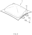
- FIG. 1 is an assembled view of a pouch type secondary battery 1 according to an embodiment of the present invention
- FIG. 2 is a perspective view illustrating a state in which the pouch type secondary battery 1 is completely assembled.
- slurry in which an electrode active material, a binder, and a plasticizer are mixed with each other is applied to a positive electrode collector and a negative electrode collector to manufacture a positive electrode plate and a negative electrode plate.
- the negative electrode collector and the positive electrode plate are respectively laminated on both sides of a separator to form an electrode assembly 10 having a predetermined shape, and then, the electrode assembly is inserted into a battery case 13, an electrolyte is injected, and a sealing process is performed.
- the electrode assembly 10 includes an electrode tab 11.
- the electrode tab 11 is connected to each of a positive electrode and a negative electrode of the electrode assembly 10 to protrude to the outside of the electrode assembly 10, thereby providing a path, through which electrons moves, between the inside and outside of the electrode assembly 10.
- a collecting plate of the electrode assembly 10 is constituted by a portion coated with an electrode active material and a distal end, on which the electrode active material is not applied, i.e., a non-coating portion.
- the electrode tab 111 may be formed by cutting the non-coating portion or by connecting a separate conductive member to the non-coating portion through ultrasonic welding.
- the electrode tabs 11 may protrude from one side of the electrode assembly 10 in the same direction, but the present invention is not limited thereto.
- the electrode tabs 11 may protrude in directions different from each other.
- the electrode lead 12 is connected to the electrode tab 11 through spot welding.
- the electrode lead 12 according to an embodiment of the present invention is provided in plurality. Also, in the plurality of electrode leads 12, a first electrode lead (see reference numeral 12a of FIG. 4 ) is connected to the electrode tab 11 of the electrode assembly 10, and a second electrode lead (see reference numeral 12b of FIG. 4 ) protrudes to the outside of a battery case 13.
- the first and second electrode leads 12a and 12b will be described below in detail.
- a portion of the electrode lead 12 is surrounded by an insulation part 14.
- the insulation part 14 may be disposed to be limited within a sealing part, at which an upper pouch 131 and a lower pouch 132 are thermally fused, so as to bonded to the battery case 13.
- the insulation part 14 may be made of a nonconductor having non-conductivity, which is not electrically conductive.
- an insulation tape which is easily attached to the electrode lead 12 and has a relatively thin thickness is mainly used as the insulation part 14, the present invention is not limited thereto.
- various members may be used as the insulation part 14 as long as the members are capable of insulating the electrode lead 12.
- the electrode lead 12 may extend in the same direction or extend in directions different from each other according to the formation positions of the positive electrode tab 111 and the negative electrode tab 112.
- the positive electrode lead 121 and the negative electrode lead 122 may be made of materials different from each other. That is, the positive electrode lead 121 may be made of the same material as the positive electrode plate, i.e., an aluminum (Al) material, and the negative electrode lead 122 may be made of the same material as the negative electrode plate, i.e., a copper (Cu) material or a copper material coated with nickel (Ni). Also, a portion of the electrode lead 12, which protrudes to the outside of the battery case 13, may be provided as a terminal part and electrically connected to an external terminal.
- the battery case 13 may be a pouch made of a flexible material. Also, th battery case 13 accommodates the electrode assembly 10 so that a portion of the electrode lead 12, i.e., the terminal part is exposed and then is sealed. As illustrated in FIG. 1 , the battery case 13 includes the upper pouch 131 and the lower pouch 132. A space in which the electrode assembly 10 is accommodated may be provided in the lower pouch 132, and upper pouch 131 may be disposed on the space to cover the space so that the electrode assembly 10 is not separated to the outside of the battery case 13. As illustrated in FIG. 1 , the upper pouch 131 and the lower pouch 132 may be separately provided, but the present invention is not limited thereto. For example, the upper pouch 131 and the lower pouch 132 may be manufactured through various manners, that is, one side of the upper pouch 131 and one side of the lower pouch 132 may be connected to each other.
- the electrode assembly 10 When the electrode lead 12 is connected to the electrode tab 11 of the electrode assembly 10, and the insulation part 14 is provided on a portion of the electrode lead 12, the electrode assembly 10 may be accommodated in the space provided in the lower pouch 132, and the upper pouch 131 may cover an upper portion of the space. Also, when the electrolyte is injected, and the sealing part provided on an edge of each of the upper pouch 131 and the lower pouch 132 is sealed to manufacture the secondary battery 1 as illustrated in FIG. 2 .
- FIG. 3 is a perspective view illustrating a state in which the pouch type secondary battery 1 is expanded in volume according to an embodiment of the present invention.
- the battery case 13 may be preferably a pouch made of a flexible material.
- the case in which the battery case 13 is the pouch will be described.
- the battery case 13 accommodating the electrode assembly 10 includes a gas barrier layer and a sealant layer.
- the gas barrier layer blocks introduction and discharge of a gas
- aluminum (Al) foil is mainly used as the gas barrier layer.
- the sealant layer is disposed in the innermost layer and directly contacts the electrode assembly 10.
- polypropylene (PP) or the like is mainly used for the sealant layer.
- a surface protection layer may be further provided on an upper portion of the gas barrier layer. The surface protection layer may be disposed in the outermost layer and cause friction and collision often with the outside.
- a nylon resin or PET which mainly has abrasion resistance and heat resistance, is used for the surface protection layer.
- the pouch type battery case 13 may be manufactured by processing a film having the above-described lamination structure into the form of a bag.
- the electrolyte is injected.
- the sealant layers may be bonded to each other to seal the battery case 13.
- the sealant layer since the sealant layer directly contacts the electrode assembly 10, the sealant layer may have to have insulating properties. Also, since the sealant contacts the electrolyte, the sealant layer may have to have corrosion resistance. Also, since the inside of the battery case 13 is completely sealed to prevent materials from moving between the inside and outside of the battery case 13, high sealability has to be realized.
- the sealing part on which the sealant layers are bonded to each other has to have superior thermal bonding strength.
- a polyolefin-based resin such as polypropylene (PP) or polyethylene (PE) may be used for the sealant layer.
- polypropylene (PP) is excellent in mechanical properties such as tensile strength, rigidity, surface hardness, abrasion resistance, and heat resistance and chemical properties such as corrosion resistance and thus is mainly used for producing the sealant layer.
- the charging and discharging are performed by oxidation and reduction reactions.
- an electrochemical reaction between the electrolyte and the electrode active material generates a gas to some degree.
- an abnormally more gas may be generated by overcharging or short-circuiting due to an abnormal reaction in the electrode assembly 10.
- the pouch type secondary battery 1 is expanded in volume as illustrated in FIG. 3 .
- techniques for physically interrupting the electrical connection such as interruption of the connection between the electrode tab 11 and the electrode lead 12 when the secondary battery 1 is expanded in volume have been proposed.
- FIG. 4 is a partial cross-sectional view taken along line A-A' of FIG. 2 in the pouch type secondary battery 1 according to an embodiment of the present invention.
- the electrode lead 12 is provided in plurality. That is, the electrode lead 12 includes a first electrode lead 12a connected to the electrode tab 11 of the electrode assembly 10 and a second electrode lead 12b protruding to the outside of the battery case 13. Also, one surface of the first electrode lead 12a and one surface of the second electrode lead 12b are bonded to each other through a connection part 15 and thus connected to each other.
- the 'detachment' means that an adsorbed or attached part is separated.
- at least one notch 16 is provided on the bonding surface of at least one electrode lead 12, which is bonded through the connection part 15.
- the notch 16 is provided in plurality, the plurality of notches 16 are arranged at predetermined intervals.
- the bonding surface may have a somewhat wide area.
- first and second electrode leads 12a and 12b are disposed on different planes so that upper and lower surfaces thereof are connected to each other instead that the first and second electrode leads 12a and 12b are disposed on the same plane so that side surfaces thereof are connected to each other.
- a stepped portion may be provided on the portion at which the first and second electrode leads 12a and 12b are connected to each other. The notch 16 will be described below in detail.
- connection part 15 connecting the first and second electrode leads 12a and 12b to each other may have a thin film shape having conductivity. Particularly, it is preferable that the connection part 15 has a very thin thickness of 1 ⁇ m to 500 ⁇ m. Thus, even though the first and second electrode leads 12a and 12b form a stepped portion therebetween, a size of the stepped portion may not be excessively large, and the electricity generated from the electrode assembly 10 may be easily discharged to the outside.
- the connection part 15 may be made of a polymer that is a conductive material.
- the conductive material may include at least one of: natural or artificial graphite; carbon black such as carbon black, acetylene black, Ketjen black, channel black, furnace black, lamp black, and summer black; conductive fiber such as carbon fiber or metal fiber; metal powders such as carbon fluoride, aluminum, nickel, gold, silver, and copper powder; powder having a core/shell structure coated with a different kind of metal on one kind of metal; conductive whiskey such as zinc oxide and potassium titanate; conductive metal oxide such as titanium oxide; and conductive materials such as polyphenylene derivatives.
- carbon black such as carbon black, acetylene black, Ketjen black, channel black, furnace black, lamp black, and summer black
- conductive fiber such as carbon fiber or metal fiber
- metal powders such as carbon fluoride, aluminum, nickel, gold, silver, and copper powder
- powder having a core/shell structure coated with a different kind of metal on one kind of metal conductive whiskey such as zinc oxide and potassium titanate
- conductive metal oxide such as titanium oxide
- the polymer may include at least one of an acrylic resin, an epoxy resin, an ethylene propylene diene monomer (EPDM) resin, a chlorinated polyethylene (CPE) resin, silicone, polyurethane, an urea resin, a melamine resin, a phenol resin, an unsaturated ester resin, polypropylene (PP), polyethylene (PE), polyimide, and polyamide, and most preferably, an acrylic resin.
- an acrylic resin an epoxy resin, an ethylene propylene diene monomer (EPDM) resin, a chlorinated polyethylene (CPE) resin, silicone, polyurethane, an urea resin, a melamine resin, a phenol resin, an unsaturated ester resin, polypropylene (PP), polyethylene (PE), polyimide, and polyamide, and most preferably, an acrylic resin.
- EPDM ethylene propylene diene monomer
- CPE chlorinated polyethylene
- silicone silicone
- polyurethane an urea resin
- a portion of the electrode lead 12 is surrounded by the insulation part 14.
- a relatively high pressure may be applied to a portion contacting the electrode lead 12 to damage the sealant layer of the battery case 13. Since the sealant layer directly contacts the electrode assembly 10 as described above, the sealant layer may have insulating properties. However, if the sealant layer is damaged, the electricity may flows to the battery case 13 through the electrode lead 12. Particularly, since the gas barrier layer of the battery case 13 is made of a metal such as aluminum, if the sealant layer is partially damaged to expose the gas barrier layer, the electricity may easily flow due to the contact with the electrode lead 12.
- the insulation part 14 may be made of a nonconductor having non-conductivity, which is not electrically conductive. Also, the insulation part 14 has high mechanical strength and heat resistance. Thus, when the upper pouch 131 and the lower pouch 132 are thermally fused, the insulation part 14 may be maintained in shape to prevent the electrode lead 12 and the gas barrier layer from contacting each other even through a portion of the sealant layer is damaged. Thus, the electricity generated from the electrode assembly 10 may be prevented from flowing to the battery case 13 through the electrode lead 12. Also, the insulation part 14 has high bonding force. Thus, the insulation part 14 may be disposed to be limited within a sealing part, at which the upper pouch 131 and the lower pouch 132 are thermally fused, so that the electrode lead 12 is bonded to the battery case 13.
- the insulating portion 14 may be made of at least one of thermoplastic, thermosetting and photocurable resins having electrical insulation properties as a polymer resin.
- an insulation tape which is easily attached to the electrode lead 12 and has a relatively thin thickness is mainly used as the insulation part 14, the present invention is not limited thereto.
- various members may be used as the insulation part 14 as long as the members are capable of insulating the electrode lead 12.
- the insulation part 14 may surround all of the first electrode lead 12a, the connection part 15, and the second electrode lead 12b. If the first electrode lead 12a or the connection part 15 is not surrounded by the insulation part 14, repulsive force may not be applied to the first electrode lead 12a and the second electrode lead 12b even though the battery case 13 is expanded. The repulsive force will be described below in detail.
- FIG. 5 is a partial cross-sectional view taken along line A-A' of FIG. 2 in the state in which the pouch type secondary battery is expanded in volume according to an embodiment of the present invention.
- the pouch type secondary battery 1 when the internal pressure of the pouch type secondary battery 13 increases, the pouch type secondary battery 1 is expanded in volume.
- an outer wall of the battery case 13 moves outward.
- upper and lower walls of the outer wall of the battery case 13 may have an area greater than that of the sidewall and be not sealed, resulting in higher flexibility.
- the upper wall of the battery case 13 may move upward, and the lower wall of the battery case 13 may move downward.
- the outer wall of the battery case 13 may move outward to apply the repulsive force to the first electrode lead 12a and the second electrode lead 12b, which are connected to each other through the insulation part 14.
- the moving force of the outer wall of the battery case 13 may more increase, and the repulsive force applied to the first electrode lead 12a and the second electrode lead 12b may more increase.
- the bonding force between the first electrode lead 12a and the second electrode lead 12b is greater than the repulsive force, as illustrated in FIG. 5 , the first electrode lead 12a and the second electrode lead 12b may be detached from each other.
- the electrical connection may be interrupted so that the electricity does not flow ever.
- the bonding force between the first and second electrode leads 12a and 12b and the connection part 15 may be less than that between the first and second electrode leads 12a and 12b and the insulation part 14.
- the bonding force between the first and second electrode leads 12a and 12b and the insulation part 14 may be maintained to maintain the sealing of the battery case, but the first and second electrode leads 12a and 12b may be detached from each other.
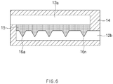
- FIG. 6 is an enlarged view of a first electrode lead 12a, a second electrode lead 12b, and a connection part 15 in the state of FIG. 4 according to an embodiment of the present invention
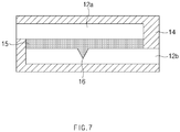
- FIG. 7 is an enlarged view of a first electrode lead 12a, a second electrode lead 12b, and a connection part 15 in the state of FIG. 5 according to another embodiment of the present invention.
- At least one or more notches 16 are arranged in a line at a predetermined interval on one surface of the second electrode lead 12b.
- the notch 16 may be preferably disposed on the bonding surface of one surface of the second electrode lead 12b, which is connected to the first electrode lead 12a.
- the notch 16 is provided on only the second electrode lead, the present invention is not limited thereto.
- the notch 16 may be provided on the first electrode lead 12a and also may be provided on all the first and second electrode leads 12a and 12b.
- the notch 16 may be disposed on a surface on which the first and second electrode leads 12a and 12b are connected to each other.
- the structure in which the notch 16 is provided on only the second electrode lead 12b will be described. However, this structure is for convenience of explanation and is not intended to limit the scope of the right scope of the present invention.
- the second electrode lead 12b may be detached up to a portion on which the notch 16 is provided. This is done because the portion, on which the notch 16 is provided, and the portion, on which the notch 16 is not provided, on the bonding surface connected to the first electrode lead 12a are different in bonding force from each other. Also, when the notch 16 is provided in plurality, the second electrode lead 12b is detached in stages up to the portion on which each of the notches 16 is provided. Thus, when the notch 16 is provided in plurality, it is preferable that the plurality of notches 16 are arranged in a line in a longitudinal direction from one end to the other end of the second electrode lead 12b.
- the notch 16 When the notch 16 is provided in plurality, the plurality of notches 16 are arranged at predetermined intervals.
- the intervals may be the same or different from each other.
- the predetermined intervals between the notches 16 may increase from one end to the other end of the second electrode lead 12b.
- the internal pressure required for detaching the second electrode lead 12b may further increase.
- the predetermined intervals between the notches 16 are the same, even though the stages in which the second electrode lead 12b is detached proceed, the increment of the internal pressure required for detaching the second electrode lead 12b may be always constant.
- the notch 16 may be recessed from one surface of the second electrode lead 12b.
- the cut surface in the recessed shape, as illustrated in FIG. 6 , when the electrode lead 12 is cut in the longitudinal direction, it is preferable that the cut surface is triangular shape. This is done because the second electrode lead 12b is easily bent in the vicinity of a vertex of the notch 16 so that the second electrode lead 12b is more easily detached.
- the notch 16 may not be limited in cut shape as long as the second electrode lead 12b is easily detached.
- the cut surface of the notch 16 may have various shapes a polygonal shape such as a rectangular shape or a pentagonal shape and a semicircular shape.
- notches 16 may be provided, the present invention is not limited thereto. For example, various numbers of notches 16 may be provided. Furthermore, according to another embodiment of the present invention, only one notch 16 may be provided as illustrated in FIG. 7 . In this case, when the second electrode lead 12b is detached up to the portion on which the one notch 16 is disposed, a warning notification device may immediately notify a warning that replacement of the secondary battery 1 is necessary to the user.
- the warning notification device is a device that measures resistance of the first and second electrode leads 12a and 12b to notify the warning to the user according to a change of the resistance.
- the resistance increases. This is done because the intensity of the resistance is inversely proportional to a cross-sectional area of a conductor.
- magnitude of a voltage is constant, the warning notification device determines that the resistance increases when magnitude of current flowing through the first and second electrode leads 12a and 12b decreases. Also, the warning notification device notifies the warning that the first and second electrode leads 12a and 12b have been detached from each other.
- the warning notification device may be a battery management system. In this case, the warning notification device may measure resistance of the battery itself to determine whether the first and second electrode leads 12a and 12b are detached from each other.
- FIG. 8 is an enlarged view illustrating a state in which the second electrode lead 12b is detached up to the portion on which the first notch 16a is provided in FIG. 6 according to an embodiment of the present invention.
- the second electrode lead 12b When a gas is generated in the battery case 13 so that the internal pressure increases to a first pressure or more, the second electrode lead 12b is detached in one stage up to the portion on which the first notch 16a is disposed. Thus, the resistance of the electrode lead 12 increases by a small amount, and the warning notification device measures the increasing resistance to notify a first warning to the user.
- the first pressure may vary according to conditions such as a size and a shape of the first notch 16a, bonding force between the connection part 15 and the second electrode lead 12b, and a distance from one end of the second electrode lead 12b to the first notch 16a.
- conditions such as a size and a shape of the first notch 16a, bonding force between the connection part 15 and the second electrode lead 12b, and a distance from one end of the second electrode lead 12b to the first notch 16a.
- the pressure desired by the user is defined as the first pressure
- the conditions are set to conditions corresponding to the defined first pressure.
- FIG. 9 is an enlarged view illustrating a state in which the second electrode lead 12b is detached up to a portion on which an n-th notch 16 is provided in FIG. 6 according to an embodiment of the present invention.
- the second electrode lead 12b When n notches 16 are provided, and a gas is continuously generated in the battery case 13 so that the internal pressure increases to an n-th pressure or more, the second electrode lead 12b is detached in n stages up to the portion on which the first notch 16 is disposed. When the second electrode lead 12b is detached in the n stages, it is immediately before the second electrode lead 12b is completely detached from the first electrode lead 12a. Thus, the warning notification device notifies an n-th warning that is the replacement of the secondary battery 1 is necessary to the user.
- the warning notification device notifies a fifth warning.
- the total number of stages in which the second electrode lead 12b is detached is one more than the number of notches 16 provided on the second electrode lead 12b. If the second electrode lead 12b is detached in (n+1)-th stages, the second electrode lead 12b is completely detached from the first electrode lead 12a. Thus, the electricity generated from the electrode assembly 10 is interrupted, and the power is not supplied from the second battery 1 any more.
- the user may grasp the state of the secondary battery 1 through the n-th warning before the secondary battery 1 is in this state and thus may replace the secondary battery 1 in advance.
- the warning notification device may notify the warning in various manners such as sounds, lamps, figures, and the like as long as the warning is notified to the user. For example, if the warning notification device notifies the warning to the user through the lamp, a blue lamp may be turned on as the first warning when the second electrode lead 12b is detached in one stage. Also, the detachment proceeds to second and third stages, green and yellow lamps are turned on to notify second and second warnings. Also, when the detachment proceeds in an n stage, a red lamp may be turned on to notify a final warning of an n-th order to the user. That is, if the current state of the secondary battery 1 is notified to the user, and thus, the user is capable of easily grasping the replacement time of the secondary battery, the warning notification device may notify the warning in various manners.
Landscapes
- Chemical & Material Sciences (AREA)
- Chemical Kinetics & Catalysis (AREA)
- Electrochemistry (AREA)
- General Chemical & Material Sciences (AREA)
- Engineering & Computer Science (AREA)
- Manufacturing & Machinery (AREA)
- Microelectronics & Electronic Packaging (AREA)
- Inorganic Chemistry (AREA)
- Materials Engineering (AREA)
- Connection Of Batteries Or Terminals (AREA)
- Sealing Battery Cases Or Jackets (AREA)
- Secondary Cells (AREA)
Abstract
Description
- The present application claims the benefit of the priority of Korean Patent Application No.
10-2017-0114613, filed on September 07, 2017 - The present invention relates to a pouch type secondary battery, and more particularly, to a pouch type secondary battery in which, when a user previously knows a replacement time before an electrical connection is interrupted in a situation in which a gas is generated in a case to increase in pressure.
- Batteries (cells) that generate electric energy through physical or chemical reaction to supply the generated electric energy to the outside are used when AC power to be supplied to the building is not obtained, or DC power is required according to the living environments surrounded by various electronic devices.
- Among such batteries, primary batteries and secondary batteries, which are chemical cells using chemical reaction, are generally used. The primary batteries are consumable cells which are collectively referred to as dry cells. On the other hand, a secondary battery is a rechargeable battery that is manufactured by using a material in which oxidation and reduction processes between current and a material are capable of being repeated many times. In general, secondary batteries include nickel-cadmium batteries, nickel-hydrogen batteries, lithium ion batteries, and lithium ion polymer batteries. Such a secondary battery is being applied to and used in small-sized products such as digital cameras, P-DVDs, MP3Ps, mobile phones, PDAs, portable game devices, power tools, E-bikes, and the like as well as large-sized products requiring high power such as electric vehicles and hybrid vehicles, power storage devices for storing surplus power or renewable energy, and backup power storage devices.
- A lithium secondary battery is generally formed by laminating a positive electrode (i.e., cathode), a separator, and a negative electrode (i.e., anode). Also, materials of the positive electrode, the separator, and the negative electrode may be selected in consideration of battery lifespan, charging/discharging capacities, temperature characteristics, stability, and the like. The charging and discharging of the lithium secondary battery are performed while lithium ions are intercalated and deintercalated from lithium metal oxide of the positive electrode to a graphite electrode of the negative electrode.
- In general, unit cells, each of which has a three-layered structure of a positive electrode/a separator/a negative electrode or a five-layered structure of a positive electrode/a separator/a negative electrode/a separator/a positive electrode or a negative electrode/a separator/a positive electrode/a separator/a negative electrode, are assembled to constitute one electrode assembly. The electrode assembly is accommodated in a specific case.
- Such a secondary battery is classified into a pouch type secondary battery and a can type secondary battery according to a material of a case accommodating the electrode assembly. In the pouch type secondary battery, an electrode assembly is accommodated in a pouch made of a flexible polymer material having a variable shape. Also, in the can type secondary battery, an electrode assembly is accommodated in a case made of a metal or plastic material having a predetermined shape.
- The secondary battery may be deteriorated in safety due to various problems such as internal short circuit due to an external impact, heat generation due to overcharging and overdischarging, electrolyte decomposition due to the generated heat, and a thermal runaway phenomenon. Particularly, explosion of the secondary battery is caused by various causes. For example, an increase in gas pressure within the secondary battery due to the decomposition of the electrolyte may also act as one cause.
- Particularly, when the secondary battery is repeatedly charged and discharged, a gas is generated by electrochemical reaction between the electrolyte and an electrode active material. Here, the generated gas may allow the secondary battery to increase in internal pressure to cause problems such as weakening of bonding force between components, damage of a case of the secondary battery, an early operation of a protection circuit, deformation of an electrode, internal short circuit, explosion, and the like. Thus, in the case of the can type secondary battery, a protection member such as a CID filter and a safety vent is provided to physically interrupt an electrical connection when an internal pressure of a case increases. However, in the case of the pouch type secondary battery according to the related art, the protection member is not sufficiently provided.
- In recent years, in the pouch type secondary battery, when the inside of a case is expanded, technologies for physically interrupting an electrical connection such as interruption of connection between an electrode tab and an electrode lead have been proposed. However, when the electrical connection is suddenly interrupted, a user that is using a product by receiving power from the secondary battery may not use the product unexpectedly. Particularly, when the product is an electric vehicle, the vehicle may be suddenly stopped while driving on the road, and thus the driver may be in a very dangerous situation.
- An object of the present invention is to provide a pouch type secondary battery in which, when a gas is generated in a case to increase in pressure, a plurality of electrode leads are attached in stages so that a user previously knows a replacement time before an electrical connection is completely interrupted.
- The objects of the present invention are not limited to the aforementioned object, but other objects not described herein will be clearly understood by those skilled in the art from descriptions below.
- To solve the above problem, a pouch type secondary battery according to an embodiment of the present invention includes: an electrode assembly in which an electrode including a positive electrode and a negative electrode and a separator are laminated; a battery case having a pouch shape to accommodate the electrode assembly; an electrode tab connected to the electrode and protruding from one side of the electrode; a first electrode lead having one end connected to the electrode tab; a second electrode lead having one end connected to the other end of the first electrode lead and the other end protruding to the outside of the battery case; and a connection part bonding the first electrode lead to the second electrode lead to connect the first and second electrode leads to each other, wherein, in at least one of the first and second electrode leads, at least one notch is provided on a boding surface on which the first and second electrode leads are bonded to each other through the connection part.
- Also, the notch may be provided in plurality, and the plurality of notches may be arranged in a line at predetermined intervals in a direction from one end to the other end of the first or second electrode lead.
- Also, all the predetermined intervals between the plurality of notches may be the same.
- Also, all the predetermined intervals between the plurality of notches may be different from each other.
- Also, all the predetermined intervals between the plurality of notches may increase in length from one to the other end of the first or second electrode lead.
- Also, the pouch type secondary battery may further include a warning notification device for notifying a warning to a user when the first and second electrode leads are detached from each other.
- Also, the warning notification device may measure resistance of the first and second electrode leads to determine whether the first and second electrode leads are detached from each other and a detached stage.
- Also, the notch may be provided plurality, and the warning notification device may notify different warnings to the user according to stages in which the first and second electrode leads are detached from each other.
- Also, the notch may have a triangular cross-sectional shape when the first or second electrode lead is cut in a longitudinal direction thereof.
- Also, the pouch type secondary battery may further include an insulation part surrounding a portion of each of the first and second electrode leads to allow the first and second electrode leads to be bonded to the battery case.
- Also, bonding force between each of the first and second electrode leads and the connection part may be less than that between each of the first and second electrode leads and the insulation part.
- Also, the insulation part may surround a portion at which the first and second electrode leads are connected to each other through the connection part.
- Also, the insulation part may be made of at least one of thermoplastic, thermosetting and photocurable resins having electrical insulation properties.
- Also, the connection part may be made of a conductive polymer including a conductive material.
- Also, the connection part may have a thickness of 1 µm to 500 µm.
- Particularities of other embodiments are included in the detailed description and drawings.
- The embodiments of the present invention may have at least the following effects.
- The plurality of electrode leads may be bonded to each other, and the plurality of notches may be provided on the bonding surface of at least one electrode lead. Thus, when the gas is generated in the case to increase in pressure, the plurality of electrode leads may be detached in stages with respect to the positions, on which the notches are provided, to increase in resistance. Thus, the user may previously know the replacement time before the electrical connection is completely interrupted.
- The effects of the prevent invention are not limited by the aforementioned description, and thus, more varied effects are involved in this specification.
-
-
FIG. 1 is an assembled view of a pouch type secondary battery according to an embodiment of the present invention. -
FIG. 2 is a perspective view illustrating a state in which the pouch type secondary battery is completely assembled. -
FIG. 3 is a perspective view illustrating a state in which the pouch type secondary battery is expanded in volume according to an embodiment of the present invention. -
FIG. 4 is a partial cross-sectional view taken along line A-A' ofFIG. 2 in the pouch type secondary battery according to an embodiment of the present invention. -
FIG. 5 is a partial cross-sectional view taken along line A-A' ofFIG. 2 in the state in which the pouch type secondary battery is expanded in volume according to an embodiment of the present invention. -
FIG. 6 is an enlarged view of a first electrode lead, a second electrode lead, and a connection part in the state ofFIG. 4 according to an embodiment of the present invention. -
FIG. 7 is an enlarged view of a first electrode lead, a second electrode lead, and a connection part in the state ofFIG. 4 according to another embodiment of the present invention. -
FIG. 8 is an enlarged view illustrating a state in which the second electrode lead is detached up to a portion on which a first notch is provided inFIG. 6 according to an embodiment of the present invention. -
FIG. 9 is an enlarged view illustrating a state in which the second electrode lead is detached up to a portion on which an n-th notch is provided inFIG. 6 according to an embodiment of the present invention. - Advantages and features of the present disclosure, and implementation methods thereof will be clarified through following embodiments described with reference to the accompanying drawings. The present invention may, however be embodied in different forms and should not be construed as limited to the embodiments set forth herein. Rather, these embodiments are provided so that this disclosure will be thorough and complete, and will fully convey the scope of the present invention to those skilled in the art. Further, the present invention is only defined by scopes of claims. Like reference numerals refer to like elements throughout.
- Unless terms used in the present invention are defined differently, all terms (including technical and scientific terms) used herein have the same meaning as generally understood by those skilled in the art. Also, unless defined clearly and apparently in the description, the terms as defined in a commonly used dictionary are not ideally or excessively construed as having formal meaning.
- In the following description, the technical terms are used only for explaining a specific exemplary embodiment while not limiting the inventive concept. In this specification, the terms of a singular form may comprise plural forms unless specifically mentioned. The meaning of ''comprises" and/or "comprising' does not exclude other components besides a mentioned component.
- Hereinafter, preferred embodiments will be described in detail with reference to the accompanying drawings.
-
FIG. 1 is an assembled view of a pouch typesecondary battery 1 according to an embodiment of the present invention, andFIG. 2 is a perspective view illustrating a state in which the pouch typesecondary battery 1 is completely assembled. - In general, in a process of manufacturing a lithium secondary battery, first, slurry in which an electrode active material, a binder, and a plasticizer are mixed with each other is applied to a positive electrode collector and a negative electrode collector to manufacture a positive electrode plate and a negative electrode plate. Thereafter, the negative electrode collector and the positive electrode plate are respectively laminated on both sides of a separator to form an
electrode assembly 10 having a predetermined shape, and then, the electrode assembly is inserted into abattery case 13, an electrolyte is injected, and a sealing process is performed. - As illustrated in
FIG. 1 , theelectrode assembly 10 includes anelectrode tab 11. Theelectrode tab 11 is connected to each of a positive electrode and a negative electrode of theelectrode assembly 10 to protrude to the outside of theelectrode assembly 10, thereby providing a path, through which electrons moves, between the inside and outside of theelectrode assembly 10. A collecting plate of theelectrode assembly 10 is constituted by a portion coated with an electrode active material and a distal end, on which the electrode active material is not applied, i.e., a non-coating portion. Also, theelectrode tab 111 may be formed by cutting the non-coating portion or by connecting a separate conductive member to the non-coating portion through ultrasonic welding. As illustrated inFIG. 1 , theelectrode tabs 11 may protrude from one side of theelectrode assembly 10 in the same direction, but the present invention is not limited thereto. For example, theelectrode tabs 11 may protrude in directions different from each other. - In the
electrode assembly 10, theelectrode lead 12 is connected to theelectrode tab 11 through spot welding. Theelectrode lead 12 according to an embodiment of the present invention is provided in plurality. Also, in the plurality of electrode leads 12, a first electrode lead (see reference numeral 12a ofFIG. 4 ) is connected to theelectrode tab 11 of theelectrode assembly 10, and a second electrode lead (see reference numeral 12b ofFIG. 4 ) protrudes to the outside of abattery case 13. The first and second electrode leads 12a and 12b will be described below in detail. Also, a portion of theelectrode lead 12 is surrounded by aninsulation part 14. Theinsulation part 14 may be disposed to be limited within a sealing part, at which anupper pouch 131 and alower pouch 132 are thermally fused, so as to bonded to thebattery case 13. Also, electricity generated from theelectrode assembly 10 may be prevented from flowing to thebattery case 13 through theelectrode lead 12, and the sealing of thebattery case 13 may be maintained. Thus, theinsulation part 14 may be made of a nonconductor having non-conductivity, which is not electrically conductive. In general, although an insulation tape which is easily attached to theelectrode lead 12 and has a relatively thin thickness is mainly used as theinsulation part 14, the present invention is not limited thereto. For example, various members may be used as theinsulation part 14 as long as the members are capable of insulating theelectrode lead 12. - The
electrode lead 12 may extend in the same direction or extend in directions different from each other according to the formation positions of thepositive electrode tab 111 and thenegative electrode tab 112. Thepositive electrode lead 121 and thenegative electrode lead 122 may be made of materials different from each other. That is, thepositive electrode lead 121 may be made of the same material as the positive electrode plate, i.e., an aluminum (Al) material, and thenegative electrode lead 122 may be made of the same material as the negative electrode plate, i.e., a copper (Cu) material or a copper material coated with nickel (Ni). Also, a portion of theelectrode lead 12, which protrudes to the outside of thebattery case 13, may be provided as a terminal part and electrically connected to an external terminal. - In the pouch type
secondary battery 1, thebattery case 13 may be a pouch made of a flexible material. Also,th battery case 13 accommodates theelectrode assembly 10 so that a portion of theelectrode lead 12, i.e., the terminal part is exposed and then is sealed. As illustrated inFIG. 1 , thebattery case 13 includes theupper pouch 131 and thelower pouch 132. A space in which theelectrode assembly 10 is accommodated may be provided in thelower pouch 132, andupper pouch 131 may be disposed on the space to cover the space so that theelectrode assembly 10 is not separated to the outside of thebattery case 13. As illustrated inFIG. 1 , theupper pouch 131 and thelower pouch 132 may be separately provided, but the present invention is not limited thereto. For example, theupper pouch 131 and thelower pouch 132 may be manufactured through various manners, that is, one side of theupper pouch 131 and one side of thelower pouch 132 may be connected to each other. - When the
electrode lead 12 is connected to theelectrode tab 11 of theelectrode assembly 10, and theinsulation part 14 is provided on a portion of theelectrode lead 12, theelectrode assembly 10 may be accommodated in the space provided in thelower pouch 132, and theupper pouch 131 may cover an upper portion of the space. Also, when the electrolyte is injected, and the sealing part provided on an edge of each of theupper pouch 131 and thelower pouch 132 is sealed to manufacture thesecondary battery 1 as illustrated inFIG. 2 . -
FIG. 3 is a perspective view illustrating a state in which the pouch typesecondary battery 1 is expanded in volume according to an embodiment of the present invention. - The
battery case 13 according to an embodiment of the present invention may be preferably a pouch made of a flexible material. Hereinafter, the case in which thebattery case 13 is the pouch will be described. - In general, the
battery case 13 accommodating theelectrode assembly 10 includes a gas barrier layer and a sealant layer. The gas barrier layer blocks introduction and discharge of a gas, and aluminum (Al) foil is mainly used as the gas barrier layer. The sealant layer is disposed in the innermost layer and directly contacts theelectrode assembly 10. Also, polypropylene (PP) or the like is mainly used for the sealant layer. Also, a surface protection layer may be further provided on an upper portion of the gas barrier layer. The surface protection layer may be disposed in the outermost layer and cause friction and collision often with the outside. Thus, a nylon resin or PET, which mainly has abrasion resistance and heat resistance, is used for the surface protection layer. - The pouch
type battery case 13 may be manufactured by processing a film having the above-described lamination structure into the form of a bag. Thus, when theelectrode assembly 10 is accommodated in the pouchtype battery case 13, the electrolyte is injected. Thereafter, when theupper pouch 131 and thelower pouch 132 may contact each other, and thermal compression is applied to the sealing part, the sealant layers may be bonded to each other to seal thebattery case 13. Here, since the sealant layer directly contacts theelectrode assembly 10, the sealant layer may have to have insulating properties. Also, since the sealant contacts the electrolyte, the sealant layer may have to have corrosion resistance. Also, since the inside of thebattery case 13 is completely sealed to prevent materials from moving between the inside and outside of thebattery case 13, high sealability has to be realized. That is, the sealing part on which the sealant layers are bonded to each other has to have superior thermal bonding strength. In general, a polyolefin-based resin such as polypropylene (PP) or polyethylene (PE) may be used for the sealant layer. Particularly, polypropylene (PP) is excellent in mechanical properties such as tensile strength, rigidity, surface hardness, abrasion resistance, and heat resistance and chemical properties such as corrosion resistance and thus is mainly used for producing the sealant layer. - Generally, in the
electrode assembly 10, the charging and discharging are performed by oxidation and reduction reactions. Here, an electrochemical reaction between the electrolyte and the electrode active material generates a gas to some degree. Furthermore, an abnormally more gas may be generated by overcharging or short-circuiting due to an abnormal reaction in theelectrode assembly 10. However, since all the respective layers are made of flexible material in the pouchtype battery case 13, if the internal pressure of thebattery case 13 increases, the pouch typesecondary battery 1 is expanded in volume as illustrated inFIG. 3 . Recently, techniques for physically interrupting the electrical connection such as interruption of the connection between theelectrode tab 11 and theelectrode lead 12 when thesecondary battery 1 is expanded in volume have been proposed. However, when the electrical connection is suddenly interrupted, a user that is using a product by receiving power from thesecondary battery 1 may not use the product unexpectedly. Particularly, when the product is an electric vehicle, the vehicle may be suddenly stopped while driving on the road, and thus the driver may be in a very dangerous situation. -
FIG. 4 is a partial cross-sectional view taken along line A-A' ofFIG. 2 in the pouch typesecondary battery 1 according to an embodiment of the present invention. - In the pouch type
secondary battery 1 according to an embodiment of the present invention, as illustrated inFIG. 4 , theelectrode lead 12 is provided in plurality. That is, theelectrode lead 12 includes afirst electrode lead 12a connected to theelectrode tab 11 of theelectrode assembly 10 and asecond electrode lead 12b protruding to the outside of thebattery case 13. Also, one surface of thefirst electrode lead 12a and one surface of thesecond electrode lead 12b are bonded to each other through aconnection part 15 and thus connected to each other. - As described below, when the internal pressure of the
battery case 13 increases, thefirst electrode lead 12a and thesecond electrode lead 12b are detached from each other in stages (here, the 'detachment' means that an adsorbed or attached part is separated). Also, to detach thefirst electrode lead 12a and thesecond electrode lead 12b from each other in stages, at least onenotch 16 is provided on the bonding surface of at least oneelectrode lead 12, which is bonded through theconnection part 15. When thenotch 16 is provided in plurality, the plurality ofnotches 16 are arranged at predetermined intervals. Thus, to form the plurality ofnotches 16, the bonding surface may have a somewhat wide area. Thus, it is preferable that the first and second electrode leads 12a and 12b are disposed on different planes so that upper and lower surfaces thereof are connected to each other instead that the first and second electrode leads 12a and 12b are disposed on the same plane so that side surfaces thereof are connected to each other. Thus, as illustrated inFIG. 4 , a stepped portion may be provided on the portion at which the first and second electrode leads 12a and 12b are connected to each other. Thenotch 16 will be described below in detail. - The
connection part 15 connecting the first and second electrode leads 12a and 12b to each other may have a thin film shape having conductivity. Particularly, it is preferable that theconnection part 15 has a very thin thickness of 1 µm to 500 µm. Thus, even though the first and second electrode leads 12a and 12b form a stepped portion therebetween, a size of the stepped portion may not be excessively large, and the electricity generated from theelectrode assembly 10 may be easily discharged to the outside. For this, theconnection part 15 may be made of a polymer that is a conductive material. - The conductive material may include at least one of: natural or artificial graphite; carbon black such as carbon black, acetylene black, Ketjen black, channel black, furnace black, lamp black, and summer black; conductive fiber such as carbon fiber or metal fiber; metal powders such as carbon fluoride, aluminum, nickel, gold, silver, and copper powder; powder having a core/shell structure coated with a different kind of metal on one kind of metal; conductive whiskey such as zinc oxide and potassium titanate; conductive metal oxide such as titanium oxide; and conductive materials such as polyphenylene derivatives.
- The polymer may include at least one of an acrylic resin, an epoxy resin, an ethylene propylene diene monomer (EPDM) resin, a chlorinated polyethylene (CPE) resin, silicone, polyurethane, an urea resin, a melamine resin, a phenol resin, an unsaturated ester resin, polypropylene (PP), polyethylene (PE), polyimide, and polyamide, and most preferably, an acrylic resin.
- As described above, a portion of the
electrode lead 12 is surrounded by theinsulation part 14. In a process of sealing theupper pouch 131 and thelower pouch 132, a relatively high pressure may be applied to a portion contacting theelectrode lead 12 to damage the sealant layer of thebattery case 13. Since the sealant layer directly contacts theelectrode assembly 10 as described above, the sealant layer may have insulating properties. However, if the sealant layer is damaged, the electricity may flows to thebattery case 13 through theelectrode lead 12. Particularly, since the gas barrier layer of thebattery case 13 is made of a metal such as aluminum, if the sealant layer is partially damaged to expose the gas barrier layer, the electricity may easily flow due to the contact with theelectrode lead 12. - Thus, the
insulation part 14 may be made of a nonconductor having non-conductivity, which is not electrically conductive. Also, theinsulation part 14 has high mechanical strength and heat resistance. Thus, when theupper pouch 131 and thelower pouch 132 are thermally fused, theinsulation part 14 may be maintained in shape to prevent theelectrode lead 12 and the gas barrier layer from contacting each other even through a portion of the sealant layer is damaged. Thus, the electricity generated from theelectrode assembly 10 may be prevented from flowing to thebattery case 13 through theelectrode lead 12. Also, theinsulation part 14 has high bonding force. Thus, theinsulation part 14 may be disposed to be limited within a sealing part, at which theupper pouch 131 and thelower pouch 132 are thermally fused, so that theelectrode lead 12 is bonded to thebattery case 13. In general, the insulatingportion 14 may be made of at least one of thermoplastic, thermosetting and photocurable resins having electrical insulation properties as a polymer resin. In general, although an insulation tape which is easily attached to theelectrode lead 12 and has a relatively thin thickness is mainly used as theinsulation part 14, the present invention is not limited thereto. For example, various members may be used as theinsulation part 14 as long as the members are capable of insulating theelectrode lead 12. - As illustrated in
FIG. 4 , theinsulation part 14 may surround all of thefirst electrode lead 12a, theconnection part 15, and thesecond electrode lead 12b. If thefirst electrode lead 12a or theconnection part 15 is not surrounded by theinsulation part 14, repulsive force may not be applied to thefirst electrode lead 12a and thesecond electrode lead 12b even though thebattery case 13 is expanded. The repulsive force will be described below in detail. -
FIG. 5 is a partial cross-sectional view taken along line A-A' ofFIG. 2 in the state in which the pouch type secondary battery is expanded in volume according to an embodiment of the present invention. - As described above, when the internal pressure of the pouch type
secondary battery 13 increases, the pouch typesecondary battery 1 is expanded in volume. Thus, as illustrated inFIG. 5 , an outer wall of thebattery case 13 moves outward. Here, upper and lower walls of the outer wall of thebattery case 13 may have an area greater than that of the sidewall and be not sealed, resulting in higher flexibility. Thus, the upper wall of thebattery case 13 may move upward, and the lower wall of thebattery case 13 may move downward. - When the
secondary battery 1 is expanded in volume, as illustrated inFIG. 5 , the outer wall of thebattery case 13 may move outward to apply the repulsive force to thefirst electrode lead 12a and thesecond electrode lead 12b, which are connected to each other through theinsulation part 14. Thus, as the internal pressure of thebattery case 13 gradually increases, the moving force of the outer wall of thebattery case 13 may more increase, and the repulsive force applied to thefirst electrode lead 12a and thesecond electrode lead 12b may more increase. When the bonding force between thefirst electrode lead 12a and thesecond electrode lead 12b is greater than the repulsive force, as illustrated inFIG. 5 , thefirst electrode lead 12a and thesecond electrode lead 12b may be detached from each other. Thus, the electrical connection may be interrupted so that the electricity does not flow ever. However, the bonding force between the first and second electrode leads 12a and 12b and theconnection part 15 may be less than that between the first and second electrode leads 12a and 12b and theinsulation part 14. Thus, when the repulsive force is applied to thefirst electrode lead 12a and thesecond electrode lead 12b, the bonding force between the first and second electrode leads 12a and 12b and theinsulation part 14 may be maintained to maintain the sealing of the battery case, but the first and second electrode leads 12a and 12b may be detached from each other. -
FIG. 6 is an enlarged view of afirst electrode lead 12a, asecond electrode lead 12b, and aconnection part 15 in the state ofFIG. 4 according to an embodiment of the present invention, andFIG. 7 is an enlarged view of afirst electrode lead 12a, asecond electrode lead 12b, and aconnection part 15 in the state ofFIG. 5 according to another embodiment of the present invention. - At least one or
more notches 16 are arranged in a line at a predetermined interval on one surface of thesecond electrode lead 12b. Here, thenotch 16 may be preferably disposed on the bonding surface of one surface of thesecond electrode lead 12b, which is connected to thefirst electrode lead 12a. - As illustrated in
FIG. 6 , although thenotch 16 is provided on only the second electrode lead, the present invention is not limited thereto. For example, thenotch 16 may be provided on thefirst electrode lead 12a and also may be provided on all the first and second electrode leads 12a and 12b. Here, thenotch 16 may be disposed on a surface on which the first and second electrode leads 12a and 12b are connected to each other. Hereinafter, the structure in which thenotch 16 is provided on only thesecond electrode lead 12b will be described. However, this structure is for convenience of explanation and is not intended to limit the scope of the right scope of the present invention. - Since the
notch 16 is provided on thesecond electrode lead 12b, when thesecond electrode lead 12b is detached from thefirst electrode lead 12a, thesecond electrode lead 12b may be detached up to a portion on which thenotch 16 is provided. This is done because the portion, on which thenotch 16 is provided, and the portion, on which thenotch 16 is not provided, on the bonding surface connected to thefirst electrode lead 12a are different in bonding force from each other. Also, when thenotch 16 is provided in plurality, thesecond electrode lead 12b is detached in stages up to the portion on which each of thenotches 16 is provided. Thus, when thenotch 16 is provided in plurality, it is preferable that the plurality ofnotches 16 are arranged in a line in a longitudinal direction from one end to the other end of thesecond electrode lead 12b. - When the
notch 16 is provided in plurality, the plurality ofnotches 16 are arranged at predetermined intervals. Here, the intervals may be the same or different from each other. Particularly, as illustrated inFIG. 6 , the predetermined intervals between thenotches 16 may increase from one end to the other end of thesecond electrode lead 12b. In this case, as the stages, in which thesecond electrode lead 12b is detached, proceed, the internal pressure required for detaching thesecond electrode lead 12b may further increase. However, if the predetermined intervals between thenotches 16 are the same, even though the stages in which thesecond electrode lead 12b is detached proceed, the increment of the internal pressure required for detaching thesecond electrode lead 12b may be always constant. - The
notch 16 may be recessed from one surface of thesecond electrode lead 12b. Here, in the recessed shape, as illustrated inFIG. 6 , when theelectrode lead 12 is cut in the longitudinal direction, it is preferable that the cut surface is triangular shape. This is done because thesecond electrode lead 12b is easily bent in the vicinity of a vertex of thenotch 16 so that thesecond electrode lead 12b is more easily detached. However, thenotch 16 may not be limited in cut shape as long as thesecond electrode lead 12b is easily detached. For example, the cut surface of thenotch 16 may have various shapes a polygonal shape such as a rectangular shape or a pentagonal shape and a semicircular shape. - As illustrated in
FIG. 6 , although fivenotches 16 may be provided, the present invention is not limited thereto. For example, various numbers ofnotches 16 may be provided. Furthermore, according to another embodiment of the present invention, only onenotch 16 may be provided as illustrated inFIG. 7 . In this case, when thesecond electrode lead 12b is detached up to the portion on which the onenotch 16 is disposed, a warning notification device may immediately notify a warning that replacement of thesecondary battery 1 is necessary to the user. - The warning notification device is a device that measures resistance of the first and second electrode leads 12a and 12b to notify the warning to the user according to a change of the resistance. As the first and second electrode leads 12a and 12b are detached from each other, i.e., as the bonding surface between the first and second electrode leads 12a and 12b decreases in area, the resistance increases. This is done because the intensity of the resistance is inversely proportional to a cross-sectional area of a conductor. However, magnitude of a voltage is constant, the warning notification device determines that the resistance increases when magnitude of current flowing through the first and second electrode leads 12a and 12b decreases. Also, the warning notification device notifies the warning that the first and second electrode leads 12a and 12b have been detached from each other. The warning notification device may be a battery management system. In this case, the warning notification device may measure resistance of the battery itself to determine whether the first and second electrode leads 12a and 12b are detached from each other.
-
FIG. 8 is an enlarged view illustrating a state in which thesecond electrode lead 12b is detached up to the portion on which thefirst notch 16a is provided inFIG. 6 according to an embodiment of the present invention. - When a gas is generated in the
battery case 13 so that the internal pressure increases to a first pressure or more, thesecond electrode lead 12b is detached in one stage up to the portion on which thefirst notch 16a is disposed. Thus, the resistance of theelectrode lead 12 increases by a small amount, and the warning notification device measures the increasing resistance to notify a first warning to the user. - Here, the first pressure may vary according to conditions such as a size and a shape of the
first notch 16a, bonding force between theconnection part 15 and thesecond electrode lead 12b, and a distance from one end of thesecond electrode lead 12b to thefirst notch 16a. Thus, a relationship between the conditions and the first pressure is experimentally derived in advance. Also, the pressure desired by the user is defined as the first pressure, and the conditions are set to conditions corresponding to the defined first pressure. Thus, when the internal pressure of thebattery case 13 increases to be equal to or greater than the first pressure defined by the user, thesecond electrode lead 12b is detached in one stage. -
FIG. 9 is an enlarged view illustrating a state in which thesecond electrode lead 12b is detached up to a portion on which an n-th notch 16 is provided inFIG. 6 according to an embodiment of the present invention. - When
n notches 16 are provided, and a gas is continuously generated in thebattery case 13 so that the internal pressure increases to an n-th pressure or more, thesecond electrode lead 12b is detached in n stages up to the portion on which thefirst notch 16 is disposed. When thesecond electrode lead 12b is detached in the n stages, it is immediately before thesecond electrode lead 12b is completely detached from thefirst electrode lead 12a. Thus, the warning notification device notifies an n-th warning that is the replacement of thesecondary battery 1 is necessary to the user. - For example, as illustrated in
FIG. 9 , when fivenotches 16 are provided, and thus, the internal pressure of thebattery case 13 increases to a fifth pressure or more, thesecond electrode lead 12b is detached in fifth stages up to the portion on which thefifth notch 16 is disposed. Also, the warning notification device notifies a fifth warning. - The total number of stages in which the
second electrode lead 12b is detached is one more than the number ofnotches 16 provided on thesecond electrode lead 12b. If thesecond electrode lead 12b is detached in (n+1)-th stages, thesecond electrode lead 12b is completely detached from thefirst electrode lead 12a. Thus, the electricity generated from theelectrode assembly 10 is interrupted, and the power is not supplied from thesecond battery 1 any more. The user may grasp the state of thesecondary battery 1 through the n-th warning before thesecondary battery 1 is in this state and thus may replace thesecondary battery 1 in advance. - The warning notification device may notify the warning in various manners such as sounds, lamps, figures, and the like as long as the warning is notified to the user. For example, if the warning notification device notifies the warning to the user through the lamp, a blue lamp may be turned on as the first warning when the
second electrode lead 12b is detached in one stage. Also, the detachment proceeds to second and third stages, green and yellow lamps are turned on to notify second and second warnings. Also, when the detachment proceeds in an n stage, a red lamp may be turned on to notify a final warning of an n-th order to the user. That is, if the current state of thesecondary battery 1 is notified to the user, and thus, the user is capable of easily grasping the replacement time of the secondary battery, the warning notification device may notify the warning in various manners. - Those with ordinary skill in the technical field of the present invention pertains will be understood that the present invention can be carried out in other specific forms without changing the technical idea or essential features. Therefore, the above-disclosed embodiments are to be considered illustrative and not restrictive. Accordingly, the scope of the present invention is defined by the appended claims rather than the foregoing description and the exemplary embodiments described therein. Various modifications made within the meaning of an equivalent of the claims of the invention and within the claims are to be regarded to be in the scope of the present invention.
Claims (15)
- A pouch type secondary battery comprising:an electrode assembly in which an electrode comprising a positive electrode and a negative electrode and a separator are laminated;a battery case having a pouch shape to accommodate the electrode assembly;an electrode tab connected to the electrode and protruding from one side of the electrode;a first electrode lead having one end connected to the electrode tab;a second electrode lead having one end connected to the other end of the first electrode lead and the other end protruding to the outside of the battery case; anda connection part bonding the first electrode lead to the second electrode lead to connect the first and second electrode leads to each other,wherein, in at least one of the first and second electrode leads, at least one notch is provided on a boding surface on which the first and second electrode leads are bonded to each other through the connection part.
- The pouch type secondary battery of claim 1, wherein the notch is provided in plurality, and
the plurality of notches are arranged in a line at predetermined intervals in a direction from one end to the other end of the first or second electrode lead. - The pouch type secondary battery of claim 2, wherein all the predetermined intervals between the plurality of notches are the same.
- The pouch type secondary battery of claim 2, wherein all the predetermined intervals between the plurality of notches are different from each other.
- The pouch type secondary battery of claim 4, wherein all the predetermined intervals between the plurality of notches increase in length from one to the other end of the first or second electrode lead.
- The pouch type secondary battery of claim 1, further comprising a warning notification device for notifying a warning to a user when the first and second electrode leads are detached from each other.
- The pouch type secondary battery of claim 6, wherein the warning notification device measures resistance of the first and second electrode leads to determine whether the first and second electrode leads are detached from each other and a detached stage.
- The pouch type secondary battery of claim 6, wherein the notch is provided plurality, and
the warning notification device notifies different warnings to the user according to stages in which the first and second electrode leads are detached from each other. - The pouch type secondary battery of claim 1, wherein the notch has a triangular cross-sectional shape when the first or second electrode lead is cut in a longitudinal direction thereof.
- The pouch type secondary battery of claim 1, further comprising an insulation part surrounding a portion of each of the first and second electrode leads to allow the first and second electrode leads to be bonded to the battery case.
- The pouch type secondary battery of claim 10, wherein bonding force between each of the first and second electrode leads and the connection part is less than that between each of the first and second electrode leads and the insulation part.
- The pouch type secondary battery of claim 10, wherein the insulation part surrounds a portion at which the first and second electrode leads are connected to each other through the connection part.
- The pouch type secondary battery of claim 10, wherein the insulation part is made of at least one of thermoplastic, thermosetting and photocurable resins having electrical insulation properties.
- The pouch type secondary battery of claim 1, wherein the connection part is made of a conductive polymer comprising a conductive material.
- The pouch type secondary battery of claim 1, wherein the connection part has a thickness of 1 µm to 500 µm.
Applications Claiming Priority (2)
| Application Number | Priority Date | Filing Date | Title |
|---|---|---|---|
| KR1020170114613A KR102288121B1 (en) | 2017-09-07 | 2017-09-07 | The Pouch Type Secondary Battery |
| PCT/KR2018/009137 WO2019050177A1 (en) | 2017-09-07 | 2018-08-09 | Pouch-type secondary battery |
Publications (3)
| Publication Number | Publication Date |
|---|---|
| EP3544089A1 true EP3544089A1 (en) | 2019-09-25 |
| EP3544089A4 EP3544089A4 (en) | 2020-03-18 |
| EP3544089B1 EP3544089B1 (en) | 2022-04-13 |
Family
ID=65634395
Family Applications (1)
| Application Number | Title | Priority Date | Filing Date |
|---|---|---|---|
| EP18854422.5A Active EP3544089B1 (en) | 2017-09-07 | 2018-08-09 | Pouch-type secondary battery |
Country Status (7)
| Country | Link |
|---|---|
| US (1) | US11258139B2 (en) |
| EP (1) | EP3544089B1 (en) |
| JP (1) | JP7055427B2 (en) |
| KR (1) | KR102288121B1 (en) |
| CN (1) | CN110050362B (en) |
| PL (1) | PL3544089T3 (en) |
| WO (1) | WO2019050177A1 (en) |
Cited By (1)
| Publication number | Priority date | Publication date | Assignee | Title |
|---|---|---|---|---|
| US11258139B2 (en) | 2017-09-07 | 2022-02-22 | Lg Energy Solution, Ltd. | Pouch type secondary battery |
Families Citing this family (5)
| Publication number | Priority date | Publication date | Assignee | Title |
|---|---|---|---|---|
| KR20210062139A (en) * | 2019-11-20 | 2021-05-31 | 주식회사 엘지화학 | The Method For Manufacturing Electrode Lead And The Pouch Type Secondary Battery |
| KR20210101520A (en) | 2020-02-10 | 2021-08-19 | 주식회사 엘지에너지솔루션 | Electrode Assembly Comprising Electrode Lead Coupled Part Bonded by Adhesive Portion and Spot Welding, and Pouch-Type Battery Cell Comprising the Same |
| KR20210138913A (en) * | 2020-05-13 | 2021-11-22 | 주식회사 엘지에너지솔루션 | Battery cell and battery system comprising the same |
| WO2023136641A1 (en) * | 2022-01-13 | 2023-07-20 | 주식회사 엘지에너지솔루션 | Secondary battery, battery pack, and device comprising same |
| CN115189078B (en) * | 2022-05-09 | 2023-11-14 | 东莞新能源科技有限公司 | Packaging shell, electrochemical device, preparation method of electrochemical device and electronic device |
Family Cites Families (20)
| Publication number | Priority date | Publication date | Assignee | Title |
|---|---|---|---|---|
| US4845419A (en) * | 1985-11-12 | 1989-07-04 | Norand Corporation | Automatic control means providing a low-power responsive signal, particularly for initiating data preservation operation |
| JP3540437B2 (en) * | 1995-06-05 | 2004-07-07 | 本田技研工業株式会社 | Battery status determination device |
| JPH11283608A (en) * | 1998-03-26 | 1999-10-15 | Tdk Corp | Electrode for battery, manufacture thereof and battery |
| US6653018B2 (en) | 2000-03-17 | 2003-11-25 | Tdk Corporation | Electrochemical device |
| KR100516774B1 (en) * | 2003-10-16 | 2005-09-22 | 삼성에스디아이 주식회사 | Pouch type Lithium secondary battery |
| JP5449948B2 (en) * | 2009-09-28 | 2014-03-19 | 三洋電機株式会社 | Stacked battery and battery pack |
| US20110104520A1 (en) * | 2009-11-02 | 2011-05-05 | Changbum Ahn | Secondary battery and battery pack using the same |
| KR101192077B1 (en) | 2009-11-02 | 2012-10-17 | 삼성에스디아이 주식회사 | Secondary battery and battery pack using the same |
| US8741471B2 (en) | 2011-03-09 | 2014-06-03 | Samsung Sdi Co., Ltd. | Battery pack |
| JP5739244B2 (en) * | 2011-06-14 | 2015-06-24 | 矢崎総業株式会社 | Battery status notification unit, bus bar module, assembled battery, and battery status monitoring system |
| CN102496750B (en) * | 2011-12-20 | 2014-10-08 | 华为技术有限公司 | Battery |
| KR101370265B1 (en) | 2012-04-17 | 2014-03-04 | 주식회사 엘지화학 | Secondary battery, Element for secondary battery applied for it and Method of manufacturing the same |
| KR101488066B1 (en) | 2012-05-31 | 2015-01-29 | 주식회사 엘지화학 | Secondary battery |
| KR101808312B1 (en) * | 2013-09-26 | 2017-12-12 | 주식회사 엘지화학 | Secondary battery and Electrode lead assembly applied for the same |
| US20150180013A1 (en) * | 2013-12-19 | 2015-06-25 | Hyundai Motor Company | High voltage battery for vehicles |
| JP6439793B2 (en) * | 2014-05-02 | 2018-12-19 | 株式会社村田製作所 | Batteries, battery packs, electronic devices, electric vehicles, power storage devices, and power systems |
| KR101991058B1 (en) * | 2014-10-28 | 2019-06-19 | 주식회사 엘지화학 | Pouch type secondary battery and a method of making the same |
| EP3267512B1 (en) | 2015-04-22 | 2021-04-14 | LG Chem, Ltd. | Secondary battery having improved safety |
| KR102055853B1 (en) | 2015-08-31 | 2019-12-13 | 주식회사 엘지화학 | Pouch type lithium secondary battery with improved safety |
| KR102288121B1 (en) | 2017-09-07 | 2021-08-11 | 주식회사 엘지에너지솔루션 | The Pouch Type Secondary Battery |
-
2017
- 2017-09-07 KR KR1020170114613A patent/KR102288121B1/en active IP Right Grant
-
2018
- 2018-08-09 US US16/481,333 patent/US11258139B2/en active Active
- 2018-08-09 PL PL18854422.5T patent/PL3544089T3/en unknown
- 2018-08-09 WO PCT/KR2018/009137 patent/WO2019050177A1/en unknown
- 2018-08-09 JP JP2019549556A patent/JP7055427B2/en active Active
- 2018-08-09 EP EP18854422.5A patent/EP3544089B1/en active Active
- 2018-08-09 CN CN201880004795.XA patent/CN110050362B/en active Active
Cited By (1)
| Publication number | Priority date | Publication date | Assignee | Title |
|---|---|---|---|---|
| US11258139B2 (en) | 2017-09-07 | 2022-02-22 | Lg Energy Solution, Ltd. | Pouch type secondary battery |
Also Published As
| Publication number | Publication date |
|---|---|
| JP7055427B2 (en) | 2022-04-18 |
| WO2019050177A1 (en) | 2019-03-14 |
| JP2020510978A (en) | 2020-04-09 |
| EP3544089B1 (en) | 2022-04-13 |
| EP3544089A4 (en) | 2020-03-18 |
| US20200006740A1 (en) | 2020-01-02 |
| PL3544089T3 (en) | 2022-08-08 |
| KR20190027615A (en) | 2019-03-15 |
| CN110050362A (en) | 2019-07-23 |
| CN110050362B (en) | 2022-03-04 |
| US11258139B2 (en) | 2022-02-22 |
| KR102288121B1 (en) | 2021-08-11 |
Similar Documents
| Publication | Publication Date | Title |
|---|---|---|
| EP3544089B1 (en) | Pouch-type secondary battery | |
| US11005147B2 (en) | Pouch type secondary battery | |
| US12002974B2 (en) | Pouch type secondary battery | |
| JP4672678B2 (en) | Battery module | |
| CN110088944B (en) | Pouch-shaped secondary battery including electrode lead using conductive polymer | |
| US10340503B2 (en) | Pouch-shaped secondary battery including electrode lead having notch formed therein | |
| KR101472202B1 (en) | Pouch for secondary battery and secondary battery using the same | |
| KR20200099392A (en) | The Secondary Battery And The Battery Module | |
| EP4043614A1 (en) | Method for manufacturing electrode lead, and pouch-type secondary battery | |
| KR20210120381A (en) | The Electrode Lead, The Method For Manufacturing Thereof And The Pouch Type Secondary Battery |
Legal Events
| Date | Code | Title | Description |
|---|---|---|---|
| STAA | Information on the status of an ep patent application or granted ep patent |
Free format text: STATUS: THE INTERNATIONAL PUBLICATION HAS BEEN MADE |
|
| PUAI | Public reference made under article 153(3) epc to a published international application that has entered the european phase |
Free format text: ORIGINAL CODE: 0009012 |
|
| STAA | Information on the status of an ep patent application or granted ep patent |
Free format text: STATUS: REQUEST FOR EXAMINATION WAS MADE |
|
| 17P | Request for examination filed |
Effective date: 20190617 |
|
| AK | Designated contracting states |
Kind code of ref document: A1 Designated state(s): AL AT BE BG CH CY CZ DE DK EE ES FI FR GB GR HR HU IE IS IT LI LT LU LV MC MK MT NL NO PL PT RO RS SE SI SK SM TR |
|
| AX | Request for extension of the european patent |
Extension state: BA ME |
|
| RIC1 | Information provided on ipc code assigned before grant |
Ipc: H01M 10/48 20060101ALI20200206BHEP Ipc: H01M 2/02 20060101ALI20200206BHEP Ipc: H01M 2/34 20060101AFI20200206BHEP Ipc: H01M 2/26 20060101ALI20200206BHEP Ipc: H01M 10/0525 20100101ALI20200206BHEP Ipc: H01M 2/08 20060101ALI20200206BHEP |
|
| A4 | Supplementary search report drawn up and despatched |
Effective date: 20200217 |
|
| DAV | Request for validation of the european patent (deleted) | ||
| DAX | Request for extension of the european patent (deleted) | ||
| STAA | Information on the status of an ep patent application or granted ep patent |
Free format text: STATUS: EXAMINATION IS IN PROGRESS |
|
| 17Q | First examination report despatched |
Effective date: 20210831 |
|
| RIC1 | Information provided on ipc code assigned before grant |
Ipc: H01M 10/0525 20100101ALN20211025BHEP Ipc: H01M 50/578 20210101ALI20211025BHEP Ipc: H01M 50/572 20210101ALI20211025BHEP Ipc: H01M 50/557 20210101ALI20211025BHEP Ipc: H01M 50/543 20210101ALI20211025BHEP Ipc: H01M 50/531 20210101ALI20211025BHEP Ipc: H01M 50/183 20210101ALI20211025BHEP Ipc: H01M 50/116 20210101ALI20211025BHEP Ipc: H01M 10/48 20060101ALI20211025BHEP Ipc: H01M 50/10 20210101AFI20211025BHEP |
|
| REG | Reference to a national code |
Ref country code: DE Ref legal event code: R079 Ref document number: 602018033938 Country of ref document: DE Free format text: PREVIOUS MAIN CLASS: H01M0002340000 Ipc: H01M0050100000 |
|
| GRAP | Despatch of communication of intention to grant a patent |
Free format text: ORIGINAL CODE: EPIDOSNIGR1 |
|
| STAA | Information on the status of an ep patent application or granted ep patent |
Free format text: STATUS: GRANT OF PATENT IS INTENDED |
|
| RIC1 | Information provided on ipc code assigned before grant |
Ipc: H01M 10/0525 20100101ALN20211203BHEP Ipc: H01M 50/578 20210101ALI20211203BHEP Ipc: H01M 50/572 20210101ALI20211203BHEP Ipc: H01M 50/557 20210101ALI20211203BHEP Ipc: H01M 50/543 20210101ALI20211203BHEP Ipc: H01M 50/531 20210101ALI20211203BHEP Ipc: H01M 50/183 20210101ALI20211203BHEP Ipc: H01M 50/116 20210101ALI20211203BHEP Ipc: H01M 10/48 20060101ALI20211203BHEP Ipc: H01M 50/10 20210101AFI20211203BHEP |
|
| RAP1 | Party data changed (applicant data changed or rights of an application transferred) |
Owner name: LG ENERGY SOLUTION LTD. |
|
| INTG | Intention to grant announced |
Effective date: 20220107 |
|
| GRAS | Grant fee paid |
Free format text: ORIGINAL CODE: EPIDOSNIGR3 |
|
| GRAA | (expected) grant |
Free format text: ORIGINAL CODE: 0009210 |
|
| STAA | Information on the status of an ep patent application or granted ep patent |
Free format text: STATUS: THE PATENT HAS BEEN GRANTED |
|
| RAP3 | Party data changed (applicant data changed or rights of an application transferred) |
Owner name: LG ENERGY SOLUTION, LTD. |
|
| AK | Designated contracting states |
Kind code of ref document: B1 Designated state(s): AL AT BE BG CH CY CZ DE DK EE ES FI FR GB GR HR HU IE IS IT LI LT LU LV MC MK MT NL NO PL PT RO RS SE SI SK SM TR |
|
| REG | Reference to a national code |
Ref country code: GB Ref legal event code: FG4D |
|
| REG | Reference to a national code |
Ref country code: CH Ref legal event code: EP |
|
| REG | Reference to a national code |
Ref country code: DE Ref legal event code: R096 Ref document number: 602018033938 Country of ref document: DE |
|
| REG | Reference to a national code |
Ref country code: IE Ref legal event code: FG4D |
|
| REG | Reference to a national code |
Ref country code: AT Ref legal event code: REF Ref document number: 1484121 Country of ref document: AT Kind code of ref document: T Effective date: 20220515 |
|
| REG | Reference to a national code |
Ref country code: SE Ref legal event code: TRGR |
|
| REG | Reference to a national code |
Ref country code: LT Ref legal event code: MG9D |
|
| REG | Reference to a national code |
Ref country code: NL Ref legal event code: MP Effective date: 20220413 |
|
| REG | Reference to a national code |
Ref country code: AT Ref legal event code: MK05 Ref document number: 1484121 Country of ref document: AT Kind code of ref document: T Effective date: 20220413 |
|
| PG25 | Lapsed in a contracting state [announced via postgrant information from national office to epo] |
Ref country code: NL Free format text: LAPSE BECAUSE OF FAILURE TO SUBMIT A TRANSLATION OF THE DESCRIPTION OR TO PAY THE FEE WITHIN THE PRESCRIBED TIME-LIMIT Effective date: 20220413 |
|
| PG25 | Lapsed in a contracting state [announced via postgrant information from national office to epo] |
Ref country code: PT Free format text: LAPSE BECAUSE OF FAILURE TO SUBMIT A TRANSLATION OF THE DESCRIPTION OR TO PAY THE FEE WITHIN THE PRESCRIBED TIME-LIMIT Effective date: 20220816 Ref country code: NO Free format text: LAPSE BECAUSE OF FAILURE TO SUBMIT A TRANSLATION OF THE DESCRIPTION OR TO PAY THE FEE WITHIN THE PRESCRIBED TIME-LIMIT Effective date: 20220713 Ref country code: LT Free format text: LAPSE BECAUSE OF FAILURE TO SUBMIT A TRANSLATION OF THE DESCRIPTION OR TO PAY THE FEE WITHIN THE PRESCRIBED TIME-LIMIT Effective date: 20220413 Ref country code: HR Free format text: LAPSE BECAUSE OF FAILURE TO SUBMIT A TRANSLATION OF THE DESCRIPTION OR TO PAY THE FEE WITHIN THE PRESCRIBED TIME-LIMIT Effective date: 20220413 Ref country code: GR Free format text: LAPSE BECAUSE OF FAILURE TO SUBMIT A TRANSLATION OF THE DESCRIPTION OR TO PAY THE FEE WITHIN THE PRESCRIBED TIME-LIMIT Effective date: 20220714 Ref country code: FI Free format text: LAPSE BECAUSE OF FAILURE TO SUBMIT A TRANSLATION OF THE DESCRIPTION OR TO PAY THE FEE WITHIN THE PRESCRIBED TIME-LIMIT Effective date: 20220413 Ref country code: ES Free format text: LAPSE BECAUSE OF FAILURE TO SUBMIT A TRANSLATION OF THE DESCRIPTION OR TO PAY THE FEE WITHIN THE PRESCRIBED TIME-LIMIT Effective date: 20220413 Ref country code: BG Free format text: LAPSE BECAUSE OF FAILURE TO SUBMIT A TRANSLATION OF THE DESCRIPTION OR TO PAY THE FEE WITHIN THE PRESCRIBED TIME-LIMIT Effective date: 20220713 Ref country code: AT Free format text: LAPSE BECAUSE OF FAILURE TO SUBMIT A TRANSLATION OF THE DESCRIPTION OR TO PAY THE FEE WITHIN THE PRESCRIBED TIME-LIMIT Effective date: 20220413 |
|
| PG25 | Lapsed in a contracting state [announced via postgrant information from national office to epo] |
Ref country code: RS Free format text: LAPSE BECAUSE OF FAILURE TO SUBMIT A TRANSLATION OF THE DESCRIPTION OR TO PAY THE FEE WITHIN THE PRESCRIBED TIME-LIMIT Effective date: 20220413 Ref country code: LV Free format text: LAPSE BECAUSE OF FAILURE TO SUBMIT A TRANSLATION OF THE DESCRIPTION OR TO PAY THE FEE WITHIN THE PRESCRIBED TIME-LIMIT Effective date: 20220413 Ref country code: IS Free format text: LAPSE BECAUSE OF FAILURE TO SUBMIT A TRANSLATION OF THE DESCRIPTION OR TO PAY THE FEE WITHIN THE PRESCRIBED TIME-LIMIT Effective date: 20220813 |
|
| REG | Reference to a national code |
Ref country code: DE Ref legal event code: R097 Ref document number: 602018033938 Country of ref document: DE |
|
| PG25 | Lapsed in a contracting state [announced via postgrant information from national office to epo] |
Ref country code: SM Free format text: LAPSE BECAUSE OF FAILURE TO SUBMIT A TRANSLATION OF THE DESCRIPTION OR TO PAY THE FEE WITHIN THE PRESCRIBED TIME-LIMIT Effective date: 20220413 Ref country code: SK Free format text: LAPSE BECAUSE OF FAILURE TO SUBMIT A TRANSLATION OF THE DESCRIPTION OR TO PAY THE FEE WITHIN THE PRESCRIBED TIME-LIMIT Effective date: 20220413 Ref country code: RO Free format text: LAPSE BECAUSE OF FAILURE TO SUBMIT A TRANSLATION OF THE DESCRIPTION OR TO PAY THE FEE WITHIN THE PRESCRIBED TIME-LIMIT Effective date: 20220413 Ref country code: EE Free format text: LAPSE BECAUSE OF FAILURE TO SUBMIT A TRANSLATION OF THE DESCRIPTION OR TO PAY THE FEE WITHIN THE PRESCRIBED TIME-LIMIT Effective date: 20220413 Ref country code: DK Free format text: LAPSE BECAUSE OF FAILURE TO SUBMIT A TRANSLATION OF THE DESCRIPTION OR TO PAY THE FEE WITHIN THE PRESCRIBED TIME-LIMIT Effective date: 20220413 Ref country code: CZ Free format text: LAPSE BECAUSE OF FAILURE TO SUBMIT A TRANSLATION OF THE DESCRIPTION OR TO PAY THE FEE WITHIN THE PRESCRIBED TIME-LIMIT Effective date: 20220413 |
|
| PLBE | No opposition filed within time limit |
Free format text: ORIGINAL CODE: 0009261 |
|
| STAA | Information on the status of an ep patent application or granted ep patent |
Free format text: STATUS: NO OPPOSITION FILED WITHIN TIME LIMIT |
|
| 26N | No opposition filed |
Effective date: 20230116 |
|
| PG25 | Lapsed in a contracting state [announced via postgrant information from national office to epo] |
Ref country code: MC Free format text: LAPSE BECAUSE OF FAILURE TO SUBMIT A TRANSLATION OF THE DESCRIPTION OR TO PAY THE FEE WITHIN THE PRESCRIBED TIME-LIMIT Effective date: 20220413 Ref country code: AL Free format text: LAPSE BECAUSE OF FAILURE TO SUBMIT A TRANSLATION OF THE DESCRIPTION OR TO PAY THE FEE WITHIN THE PRESCRIBED TIME-LIMIT Effective date: 20220413 |
|
| REG | Reference to a national code |
Ref country code: CH Ref legal event code: PL |
|
| PG25 | Lapsed in a contracting state [announced via postgrant information from national office to epo] |
Ref country code: LU Free format text: LAPSE BECAUSE OF NON-PAYMENT OF DUE FEES Effective date: 20220809 Ref country code: LI Free format text: LAPSE BECAUSE OF NON-PAYMENT OF DUE FEES Effective date: 20220831 Ref country code: CH Free format text: LAPSE BECAUSE OF NON-PAYMENT OF DUE FEES Effective date: 20220831 |
|
| REG | Reference to a national code |
Ref country code: BE Ref legal event code: MM Effective date: 20220831 |
|
| PG25 | Lapsed in a contracting state [announced via postgrant information from national office to epo] |
Ref country code: SI Free format text: LAPSE BECAUSE OF FAILURE TO SUBMIT A TRANSLATION OF THE DESCRIPTION OR TO PAY THE FEE WITHIN THE PRESCRIBED TIME-LIMIT Effective date: 20220413 |
|
| P01 | Opt-out of the competence of the unified patent court (upc) registered |
Effective date: 20230512 |
|
| PG25 | Lapsed in a contracting state [announced via postgrant information from national office to epo] |
Ref country code: IE Free format text: LAPSE BECAUSE OF NON-PAYMENT OF DUE FEES Effective date: 20220809 |
|
| PG25 | Lapsed in a contracting state [announced via postgrant information from national office to epo] |
Ref country code: BE Free format text: LAPSE BECAUSE OF NON-PAYMENT OF DUE FEES Effective date: 20220831 |
|
| PGFP | Annual fee paid to national office [announced via postgrant information from national office to epo] |
Ref country code: SE Payment date: 20230721 Year of fee payment: 6 Ref country code: PL Payment date: 20230724 Year of fee payment: 6 |
|
| PG25 | Lapsed in a contracting state [announced via postgrant information from national office to epo] |
Ref country code: IT Free format text: LAPSE BECAUSE OF FAILURE TO SUBMIT A TRANSLATION OF THE DESCRIPTION OR TO PAY THE FEE WITHIN THE PRESCRIBED TIME-LIMIT Effective date: 20220413 |
|
| PG25 | Lapsed in a contracting state [announced via postgrant information from national office to epo] |
Ref country code: HU Free format text: LAPSE BECAUSE OF FAILURE TO SUBMIT A TRANSLATION OF THE DESCRIPTION OR TO PAY THE FEE WITHIN THE PRESCRIBED TIME-LIMIT; INVALID AB INITIO Effective date: 20180809 |
|
| PG25 | Lapsed in a contracting state [announced via postgrant information from national office to epo] |
Ref country code: CY Free format text: LAPSE BECAUSE OF FAILURE TO SUBMIT A TRANSLATION OF THE DESCRIPTION OR TO PAY THE FEE WITHIN THE PRESCRIBED TIME-LIMIT Effective date: 20220413 |
|
| PG25 | Lapsed in a contracting state [announced via postgrant information from national office to epo] |
Ref country code: MK Free format text: LAPSE BECAUSE OF FAILURE TO SUBMIT A TRANSLATION OF THE DESCRIPTION OR TO PAY THE FEE WITHIN THE PRESCRIBED TIME-LIMIT Effective date: 20220413 |
|
| PG25 | Lapsed in a contracting state [announced via postgrant information from national office to epo] |
Ref country code: MT Free format text: LAPSE BECAUSE OF FAILURE TO SUBMIT A TRANSLATION OF THE DESCRIPTION OR TO PAY THE FEE WITHIN THE PRESCRIBED TIME-LIMIT Effective date: 20220413 |
|
| PGFP | Annual fee paid to national office [announced via postgrant information from national office to epo] |
Ref country code: DE Payment date: 20240722 Year of fee payment: 7 |
|
| PGFP | Annual fee paid to national office [announced via postgrant information from national office to epo] |
Ref country code: GB Payment date: 20240723 Year of fee payment: 7 |
|
| PGFP | Annual fee paid to national office [announced via postgrant information from national office to epo] |
Ref country code: FR Payment date: 20240723 Year of fee payment: 7 |