EP3753514B1 - Medizinische schraubenoperationsvorrichtung und operationsroboter damit - Google Patents
Medizinische schraubenoperationsvorrichtung und operationsroboter damit Download PDFInfo
- Publication number
- EP3753514B1 EP3753514B1 EP19754459.6A EP19754459A EP3753514B1 EP 3753514 B1 EP3753514 B1 EP 3753514B1 EP 19754459 A EP19754459 A EP 19754459A EP 3753514 B1 EP3753514 B1 EP 3753514B1
- Authority
- EP
- European Patent Office
- Prior art keywords
- surgical device
- screw
- surgical
- guide
- main body
- Prior art date
- Legal status (The legal status is an assumption and is not a legal conclusion. Google has not performed a legal analysis and makes no representation as to the accuracy of the status listed.)
- Active
Links
Images


Classifications
-
- A—HUMAN NECESSITIES
- A61—MEDICAL OR VETERINARY SCIENCE; HYGIENE
- A61B—DIAGNOSIS; SURGERY; IDENTIFICATION
- A61B17/00—Surgical instruments, devices or methods
- A61B17/56—Surgical instruments or methods for treatment of bones or joints; Devices specially adapted therefor
- A61B17/58—Surgical instruments or methods for treatment of bones or joints; Devices specially adapted therefor for osteosynthesis, e.g. bone plates, screws or setting implements
- A61B17/68—Internal fixation devices, including fasteners and spinal fixators, even if a part thereof projects from the skin
- A61B17/84—Fasteners therefor or fasteners being internal fixation devices
- A61B17/86—Pins or screws or threaded wires; nuts therefor
- A61B17/8625—Shanks, i.e. parts contacting bone tissue
-
- A—HUMAN NECESSITIES
- A61—MEDICAL OR VETERINARY SCIENCE; HYGIENE
- A61B—DIAGNOSIS; SURGERY; IDENTIFICATION
- A61B17/00—Surgical instruments, devices or methods
- A61B17/16—Instruments for performing osteoclasis; Drills or chisels for bones; Trepans
- A61B17/1655—Instruments for performing osteoclasis; Drills or chisels for bones; Trepans for tapping
-
- A—HUMAN NECESSITIES
- A61—MEDICAL OR VETERINARY SCIENCE; HYGIENE
- A61B—DIAGNOSIS; SURGERY; IDENTIFICATION
- A61B17/00—Surgical instruments, devices or methods
- A61B17/16—Instruments for performing osteoclasis; Drills or chisels for bones; Trepans
- A61B17/1662—Instruments for performing osteoclasis; Drills or chisels for bones; Trepans for particular parts of the body
- A61B17/1671—Instruments for performing osteoclasis; Drills or chisels for bones; Trepans for particular parts of the body for the spine
-
- A—HUMAN NECESSITIES
- A61—MEDICAL OR VETERINARY SCIENCE; HYGIENE
- A61B—DIAGNOSIS; SURGERY; IDENTIFICATION
- A61B17/00—Surgical instruments, devices or methods
- A61B17/16—Instruments for performing osteoclasis; Drills or chisels for bones; Trepans
- A61B17/17—Guides or aligning means for drills, mills, pins or wires
- A61B17/1735—Guides or aligning means for drills, mills, pins or wires for rasps or chisels
-
- A—HUMAN NECESSITIES
- A61—MEDICAL OR VETERINARY SCIENCE; HYGIENE
- A61B—DIAGNOSIS; SURGERY; IDENTIFICATION
- A61B17/00—Surgical instruments, devices or methods
- A61B17/16—Instruments for performing osteoclasis; Drills or chisels for bones; Trepans
- A61B17/17—Guides or aligning means for drills, mills, pins or wires
- A61B17/1739—Guides or aligning means for drills, mills, pins or wires specially adapted for particular parts of the body
- A61B17/1757—Guides or aligning means for drills, mills, pins or wires specially adapted for particular parts of the body for the spine
-
- A—HUMAN NECESSITIES
- A61—MEDICAL OR VETERINARY SCIENCE; HYGIENE
- A61B—DIAGNOSIS; SURGERY; IDENTIFICATION
- A61B17/00—Surgical instruments, devices or methods
- A61B17/56—Surgical instruments or methods for treatment of bones or joints; Devices specially adapted therefor
- A61B17/58—Surgical instruments or methods for treatment of bones or joints; Devices specially adapted therefor for osteosynthesis, e.g. bone plates, screws or setting implements
- A61B17/68—Internal fixation devices, including fasteners and spinal fixators, even if a part thereof projects from the skin
- A61B17/70—Spinal positioners or stabilisers, e.g. stabilisers comprising fluid filler in an implant
- A61B17/7074—Tools specially adapted for spinal fixation operations other than for bone removal or filler handling
- A61B17/7076—Tools specially adapted for spinal fixation operations other than for bone removal or filler handling for driving, positioning or assembling spinal clamps or bone anchors specially adapted for spinal fixation
- A61B17/7082—Tools specially adapted for spinal fixation operations other than for bone removal or filler handling for driving, positioning or assembling spinal clamps or bone anchors specially adapted for spinal fixation for driving, i.e. rotating, screws or screw parts specially adapted for spinal fixation, e.g. for driving polyaxial or tulip-headed screws
-
- A—HUMAN NECESSITIES
- A61—MEDICAL OR VETERINARY SCIENCE; HYGIENE
- A61B—DIAGNOSIS; SURGERY; IDENTIFICATION
- A61B17/00—Surgical instruments, devices or methods
- A61B17/56—Surgical instruments or methods for treatment of bones or joints; Devices specially adapted therefor
- A61B17/58—Surgical instruments or methods for treatment of bones or joints; Devices specially adapted therefor for osteosynthesis, e.g. bone plates, screws or setting implements
- A61B17/88—Osteosynthesis instruments; Methods or means for implanting or extracting internal or external fixation devices
- A61B17/90—Guides therefor
-
- A—HUMAN NECESSITIES
- A61—MEDICAL OR VETERINARY SCIENCE; HYGIENE
- A61B—DIAGNOSIS; SURGERY; IDENTIFICATION
- A61B34/00—Computer-aided surgery; Manipulators or robots specially adapted for use in surgery
- A61B34/30—Surgical robots
-
- A—HUMAN NECESSITIES
- A61—MEDICAL OR VETERINARY SCIENCE; HYGIENE
- A61B—DIAGNOSIS; SURGERY; IDENTIFICATION
- A61B34/00—Computer-aided surgery; Manipulators or robots specially adapted for use in surgery
- A61B34/70—Manipulators specially adapted for use in surgery
-
- A—HUMAN NECESSITIES
- A61—MEDICAL OR VETERINARY SCIENCE; HYGIENE
- A61B—DIAGNOSIS; SURGERY; IDENTIFICATION
- A61B17/00—Surgical instruments, devices or methods
- A61B17/16—Instruments for performing osteoclasis; Drills or chisels for bones; Trepans
- A61B17/1697—Instruments for performing osteoclasis; Drills or chisels for bones; Trepans specially adapted for wire insertion
-
- A—HUMAN NECESSITIES
- A61—MEDICAL OR VETERINARY SCIENCE; HYGIENE
- A61B—DIAGNOSIS; SURGERY; IDENTIFICATION
- A61B17/00—Surgical instruments, devices or methods
- A61B2017/00367—Details of actuation of instruments, e.g. relations between pushing buttons, or the like, and activation of the tool, working tip, or the like
-
- A—HUMAN NECESSITIES
- A61—MEDICAL OR VETERINARY SCIENCE; HYGIENE
- A61B—DIAGNOSIS; SURGERY; IDENTIFICATION
- A61B17/00—Surgical instruments, devices or methods
- A61B2017/00477—Coupling
-
- A—HUMAN NECESSITIES
- A61—MEDICAL OR VETERINARY SCIENCE; HYGIENE
- A61B—DIAGNOSIS; SURGERY; IDENTIFICATION
- A61B90/00—Instruments, implements or accessories specially adapted for surgery or diagnosis and not covered by any of the groups A61B1/00 - A61B50/00, e.g. for luxation treatment or for protecting wound edges
- A61B90/03—Automatic limiting or abutting means, e.g. for safety
- A61B2090/033—Abutting means, stops, e.g. abutting on tissue or skin
- A61B2090/034—Abutting means, stops, e.g. abutting on tissue or skin abutting on parts of the device itself
Definitions
- the disclosure relates to a medical screw surgical device, a surgical robot with the same, and a not claimed surgical method of using the surgical robot with the medical screw surgical device, and more particularly to a medical screw surgical device, a surgical robot with the same, and a not claimed surgical method of using the surgical robot with the medical screw surgical device, by which time taken in surgery is shortened by simplifying surgical procedures, in particular, pedicle screw insertion surgery is quickly and easily performed, and accuracy of surgery is improved.
- a spine supporting a human body is made up of 24 vertebrae, a disc lies between adjacent vertebrae, and nerves cross the vertebrae.
- the nerves crossing the spine are pressed to thereby cause an acute pain.
- a slight pain is treated based on a physical therapy, but a severe pain needs to undergo a surgical operation that corrects the posture of the spine by inserting a fixation device for immobilizing pedicles or releases the pressure on the nerves.
- the pedicle screw insertion surgery is performed by inserting pedicle screws into a plurality of pedicles, and connecting the adjacent pedicle screws with a rod to achieve spinal fusion.
- the pedicle screw insertion surgery realigns the spine by widening a space between the pedicle compressing the nerve and the adjacent pedicle with a rod and thus prevents the pedicle from compressing the nerve.
- the pedicle screw insertion surgery is carried out by inserting the pedicle screws into a plurality of pedicles with a fastening tool called a driver and then connecting the screw heads of the pedicle screws with the rod, but has limitations that procedures up to the insertion of the pedicle screws into the pedicles are very complicated and many kinds of surgical instruments are required.
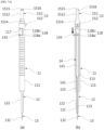
- a process of inserting the pedicle screw refers to inserting a pedicle screw S into a pedicle P as shown in FIG. 1C using a plurality of surgical instruments as shown in FIGS. 1A and 1B , and is completed by taking many procedures and steps in sequence as shown in FIGS. 1D and 1E .
- a reference wire i2 K-wire
- the process of inserting the pedicle screw has a problem that it takes long time to perform the surgery and repetitive jobs increase fatigue of a medical team because of very complicated and excessively many surgical procedures of about twelve steps, and has shortcomings that a burden of medical expenses on a patient is increased because not only many kinds of surgical instruments such as the guide pin i1, the reference wire i2, the first sleeve i3, the second sleeve i4, the third sleeve i5, the reamer T1, the screw driver T2, the hammer T3, etc. as shown in FIGS. 1A and 1B are required in surgery, but also management and maintenance of the surgical devices cause surgical costs to rise.
- surgical instruments such as the guide pin i1, the reference wire i2, the first sleeve i3, the second sleeve i4, the third sleeve i5, the reamer T1, the screw driver T2, the hammer T3, etc. as shown in FIGS. 1A and 1B are required in surgery, but also management and maintenance
- the conventional pedicle screw insertion surgery has a problem that a patient or a medical team are exposed to radiation because repetitive radiography is involved in the process of inserting the K-wire i2 or the like.
- Document US 2018/014890 A1 discloses a multi-stage dilator and cannula assembly for use in surgical procedures, including minimally invasive surgical procedures.
- the disclosure has been proposed as conceived from the foregoing grounds, and an aspect of the disclosure is to provide a medical screw surgical device, a surgical robot with the same, and a not claimed surgical method of using the surgical robot with the medical screw surgical device, by which time taken in surgery is shortened with a simple surgical process, surgery is easily performed with simple surgical instruments, and medical expenses are reduced.
- Another aspect of the disclosure is to provide a medical screw surgical device, a surgical robot with the same, and a not claimed surgical method of using the surgical robot with the medical screw surgical device, by which the robot is used to quickly and easily perform a pedicle screw insertion surgery and improve accuracy of surgery.
- the medical screw surgical device includes: a surgical device main body formed with an insertion passage inside a bar-shaped body ; an extension member provided in a lower portion of the surgical device main body and internally formed with a guide hole; a guide member movably provided in the guide hole of the extension member; and a firing member provided in the insertion passage of the surgical device main body and controlling the guide member to move up and down.
- the medical screw surgical device may further include a tool connecting member provided in an upper portion of the surgical device main body and connecting with an operation tool for applying a tightening force and a releasing force to the surgical device main body.
- the tool connecting member includes a connection body and a fixing bolt
- the connection body including a main body connector which is inserted in a top portion of the surgical device main body and formed with a fixing-bolt insertion hole, and a tool connector to which the operation tool is connected, and the fixing bolt being inserted in the fixing-bolt insertion hole of the connection body
- the surgical device main body may include a fixing bolt fastening hole in an upper portion thereof to which the fixing bolt is fastened.
- the guide member includes a thread formed on an outer circumferential surface of a guide body shaped like a pin
- the extension member includes a thread formed on an outer circumferential surface of an extension member body shaped like a pin in an opposite direction to the guide member.
- the guide member may include a stopper protrusion formed in a top portion of the guide body, and the extension member may include a protrusion-movement hole formed to have a cross-section corresponding to a cross-section of the stopper protrusion and communicating with the guide hole.
- the extension member may include a cut-open portion having a height difference on the outer circumferential surface of the extension member body, and the insertion passage of the surgical device main body may be formed with a cut-open portion insertion hole in which the cut-open portion is inserted and seated.
- the firing member may include a firing member body shaped like a bar, a support bar protruding from a bottom portion of the firing member body and being in contact with the top portion of the guide member, and a moving piece formed in a top portion of the firing member body, and the surgical device main body may include a movement guiding groove, which allows the moving piece to move up and down, and holding grooves, which communicate with the movement guiding groove and hold the moving piece in position, are formed to communicate with the insertion passage thereof.
- a surgical robot with a robot arm includes: a support arm provided in the robot arm; a surgical device holding member provided in the support arm; and the foregoing medical screw surgical device provided in the surgical device holding member.
- the support arm may be structured to include a coupling hole at an end portion of the support arm body including a curved portion
- the surgical device holding member may include a sleeve holder inserted in and locked to the coupling hole and formed with a sleeve insertion hole, and a sleeve inserted in the sleeve holder and including a surgical device insertion hole.
- a surgical method of using the surgical robot with the medical screw surgical device includes: a surgical-device mounting step of mounting the surgical device holding member to the support arm and mounting the medical screw surgical device with an operation tool; a guide-member inserting step of controlling the firing member in a forward direction to move down and hold the guide member and controlling the operation tool to insert the guide member into a surgical site; a guide-member releasing step of controlling the firing member in a reverse direction to release a binding force applied to the guide member so that the guide member can move up; an extension-member inserting step of applying the tightening force to the operation tool after carrying out the guide-member releasing step so that the extension member can ream and tap a surgical site and form the screw insertion hole; and a medical-screw inserting step of removing the operation tool including the medical screw surgical device, installing and fastening the screw coupling tool with the medical screw to the surgical device holding member, and removing the screw coupling tool.
- the guide-member inserting step may be carried out by rotating the guide member in a certain direction based on the screw portion formed on the outer circumferential surface of the guide body shaped like a pin.
- the extension-member inserting step may be carried out by rotating the extension member in an opposite direction to the rotating direction for inserting the guide member, based on the screw portion formed on the outer circumferential surface of the extension member body shaped like a pin in the opposite direction to the guide member.
- a surgical robot with the same and a surgical method of using the surgical robot with the medical screw surgical device, time taken in surgery is shortened with simple surgical procedures, and improvement in surgical efficiency and reduction of management and maintenance costs are achieved with concise and simple surgical instruments without excessively many kinds of surgical instruments such as the guide pin, the reference wire, the first sleeve, the second sleeve, the third sleeve, the reamer, the hammer, etc. which have been conventionally required in the surgery, thereby having effects on enhancing medical quality and decreasing a burden of medical expenses on a patient.
- a medical screw surgical device a surgical robot with the same, and a surgical method of using the surgical robot with the medical screw surgical device, a specially devised medical screw surgical device is mounted to the robot arm of the surgical robot to insert the medical screw, thereby omitting, reducing or simplifying the process based on manual operations using a hammer or the like. Further, it is possible to solve the conventional problem that the surgical device is unintentionally deeply inserted.
- the medical screw is inserted through guide operations of the surgical robot, thereby preventing a defective surgery and securing accuracy. Radiography is minimized, thereby having advantages of reducing exposure to radiation.
- FIGS. 2 to 8C in which like numerals refer to like elements throughout FIGS. 2 to 8C .
- illustrations and detailed descriptions about the elements that can be easily understood by those skilled in this field from the general art and the operations and effects thereof are simplified and omitted in the drawings, and illustration is made focusing on parts related to the disclosure.
- FIG. 2 is a perspective view of a medical screw surgical device according to the first embodiment of the disclosure
- FIG. 3 is an exploded perspective view of the medical screw surgical device according to the first embodiment of the disclosure
- FIG. 4A is a perspective view of a surgical device main body of the medical screw surgical device according to the first embodiment of the disclosure
- FIG. 4B is a perspective view of an extension member of the medical screw surgical device according to the first embodiment of the disclosure, in which an enlarged view shows a partially cut-open perspective view of an indicated portion
- FIG. 4C is a perspective view of a guide member of the medical screw surgical device according to the first embodiment of the disclosure.
- a medical screw surgical device 1 relates to a device used in surgery for fastening a medical screw S to a human body, includes a surgical device main body 11, an extension member 12, a guide member 13 and a firing member 14, and is characterized in that not only time taken in surgery is shortened with a simple surgical process but also surgery is easily performed with simple surgical instruments.
- the medical screw surgical device is applicable to various orthopedic surgeries for a human body, but descriptions will be made based on an example of pedicle screw insertion surgery that a medial screw S typically called a pedicle screw is inserted in a pedicle P.
- the surgical device main body 11 refers to an element that functions as a frame as shown in FIG. 4A , and includes an insertion passage 112 formed inside a bar-shaped body 111, and a fixing bolt fastening hole 115 formed in an upper portion thereof to which a fixing bolt 152 to be described later is fastened.
- the surgical device main body 11 is provided with a tool connecting member 15 on the top thereof to which an operation tool T1 (e.g. the reamer in the BACKGROUND ART) for applying a tightening force and a releasing force can be connected.
- an operation tool T1 e.g. the reamer in the BACKGROUND ART
- the tool connecting member 15 and the surgical device main body 11 may be formed as a single body.
- the tool connecting member 15 in this embodiment includes a connection body 151 and the fixing bolt 152 so as to be detachably connected to the surgical device main body 11.
- connection body 151 includes a main body connector 1511 to be inserted on the top of the surgical device main body 11, and a tool connector 1512 to connect with the operation tool T1 or the like.
- the main body connector 1511 includes a fixing-bolt insertion hole 1513 formed by transversely perforating a pin-shaped body thereof, and an annular stopper 1514 protruding like a ring to form a boundary with the tool connector 1512.
- the tool connector 1512 may be variously shaped corresponding to a connector structure of the operation tool T1 to be connected thereto.
- the tool connector 1512 is shaped like a round bar and formed with a stop protrusion 1515 and a holding groove 1516 at an end portion thereof to be used as being inserted in and connected to a connection hole of a control handle (see (c) in FIG. 8B , which includes a connection block T11 formed with a connection hole (not shown) and a handle T12 coupled to the connection block T11) connected to a well-known dilation tool T1 or pedicle screw driver T2 used as the operation tool in the conventional pedicle screw insertion surgery.
- the fixing bolt 152 is shaped like a usual bolt that includes a fastening portion inserted in and fastened to the fixing-bolt insertion hole 1513 of the connection body 151, and a head portion through which the tightening force is applied.
- the extension member 12 refers to an element that performs a reaming and tapping process to form a screw insertion hole P2, into which the medical screw S is inserted, in a surgical site such as the pedicle P as shown in FIG. 1C , and includes an extension member body 121 installed in a lower portion of the surgical device main body 11 and shaped like a round bar, and a guide hole 123 formed inside the extension member body 121.
- the extension member 12 includes a protrusion-movement hole 124 that communicates with the guide hole 123 and has a cross-section corresponding to the cross-section of a stopper protrusion 133 of the guide member 13 to be described later.
- the protrusion-movement hole 124 is formed in an upper portion of the extension member body 121 and has a range as much as protrusion (i.e. a protruding length of the guide member protruding outward from the bottom of the extension member 12) of the guide member 13, as a hole having a quadrangular cross-section with which the stopper protrusion 133 can movably mesh because the stopper protrusion 133 of the guide member 13 has a quadrangular cross-section.
- the extension member 12 is formed with a screw portion for reaming and tapping in a lower portion of the extension member body 121, and this screw portion is formed as a right-handed screw on the outer circumferential surface of the extension member body 121 shaped like a pin and has a thread 122 of which a direction is opposite to a threaded direction of the guide member.
- the tread 122 is formed like this as the screw portion of the extension member 12 in a direction opposite to the threaded direction of the guide member is because the extension member and the guide member need to be prevented from being inserted and moved in the same direction even through the extension member 12 is rotated interlocking with the guide member 13 as shown in FIGS. 7A to 8C , thereby preventing the guide member 13 from being further deeply inserted unintentionally.
- the screw portion of the guide member 13 to be described later has a left-handed screw portion 132.
- the guide member 13 may also be rotated interlocking with the extension member 12 during the reaming and tapping process and thus unintentionally deeply inserted thereby causing a defective or failed surgery.
- the extension member 12 includes a cut-open portion 127 with a height difference 126 on the outer surface of the extension member body 121 so that a portion thereof can be inserted and locked inside the surgical device main body 11.
- the cut-open portion 127 is symmetrically formed at opposite sides of the extension member body 121.
- the cut-open portions 127 are formed at the opposite sides, and therefore the outer appearance of the extension member 12 has an approximately oval-shaped cross-section in a portion where the cut-open portion is formed.
- the surgical device main body 11 includes the cut-open portion insertion hole 113 in which the cut-open portion 127 is inserted and positioned and which communicates with the insertion passage 112.
- the cut-open portion insertion hole 113 is formed as a hole having an approximately oval-shaped cross-section to match the shape of the cut-open portion in the lower portion of the surgical device main body 11.
- the guide member 13 refers to an element that is inserted in a surgical site in an initial surgical stage and performs a base hole forming function to serve as a guide pin for setting a position for forming the screw insertion hole P2 and facilitate the reaming and tapping process using the extension member.
- the guide member 13 is movably installed in the guide hole 123 and the protrusion-movement hole 124 of the extension member 12.
- the guide member 13 includes a screw portion formed in a lower portion of a guide body 131 having a pin shape and inserted in a surgical site, and the stopper protrusion 133 on a top portion of the guide body 131.
- the screw portion is formed as a left-handed screw in the guide member 13, and is characterized in that its thread 132 is formed in the opposite direction to the thread of the extension member 12.
- the reason why the tread 132 is formed like this in the direction opposite to the threaded of the extension member 12 is because the guide member and the extension member need to be prevented from being inserted and moved in the same direction even through the guide member 13 is rotated interlocking with the extension member 12 as described in the reason of forming the right-handed screw portion 122 in the extension member 12.
- the stopper protrusion 133 is formed to have a quadrangular cross-section so as to move up and down along the protrusion-movement hole 124 of the extension member 12.
- the firing member 14 refers to an element that is installed in the insertion passage 112 of the surgical device main body 11 and applies or releases a binding force to and from the guide member 13 to control the guide member 13 to move up and down, and includes a firing member body 141 shaped like a bar, a support bar 142 protruding from a bottom portion of the firing member body 141 to be in contact with the top portion of the guide member 13 and shaped like a bar having a smaller external diameter than the firing member body 141, and a moving piece 143 connected to the top portion of the firing member body 141.
- the moving piece 143 is provided to apply an external force for moving the firing member 14 up and down.
- this embodiment shows that the moving piece 143 is structured as a handle screw having a head portion and a screw portion, and the firing member body 141 is formed with a fastening hole 1411 to which the handle screw is fastened in the upper end portion thereof.
- the surgical device main body 11 includes a movement guiding groove 117 allowing the foregoing moving piece 143 to move up and down so that the support bar 142 of the firing member 14 can press and bind the top end of the guide member 13 or release the binding force, and a holding groove 118 formed communicate with the insertion passage 112 of the surgical device main body 11.
- the movement guiding groove 117 is formed as cut up and down to communicate with the insertion passage 112 of the surgical device main body 11 so that the moving piece 143 can move up and down along the movement guiding groove 117.
- the holding groove 118 may be provided in plural to communicate with the movement guiding groove 117, including a first holding groove 118a perpendicularly formed in a lower end portion of the movement guiding groove 117 so that the supporter 142 of the firing member 14 can keep pressing the top portion of the guide member 13, and a second holding groove 118b perpendicularly formed in an upper end portion of the movement guiding groove 117 so that the support bar 142 of the firing member can be separated from the top portion of the guide member 13.
- FIG. 5 is a view for describing a surgical robot with the medical screw surgical device according to the first embodiment of the disclosure, as a perspective view illustrating only a part to which the medical screw surgical device is mounted, in which the pedicle P is schematically and mimetically illustrated.
- FIG. 6 is an exploded perspective view for describing the surgical robot with the medical screw surgical device according to the first embodiment of the disclosure
- the surgical robot with the medical screw surgical device refers to a surgical robot that is loaded with the foregoing medical screw surgical device 1 to perform surgery, and includes a support arm 2 installed in a robot arm (not shown), and a surgical device holding member 3 installed in the support arm 2 and loaded with the medical screw surgical device 1.
- the support arm 2 may be variously shaped corresponding to surgical sites.
- the support arm 2 is structured to have a coupling hole 22 at an end portion of the support arm body 21 having a curved portion corresponding to the pedicle screw insertion surgery.
- the surgical device holding member 3 includes a sleeve holder 31 inserted in and locked to the coupling hole 22 of the support arm 2 and formed with a sleeve insertion hole 312, and a sleeve 32 inserted in and locked to the sleeve holder 31 and shaped like a pipe having a surgical device insertion hole.
- the sleeve holder 31 includes a holder 311 shaped like a cylinder and inserted in the coupling hole 22, and a seating protrusion 313 protruding like a ring from the top end of the holder 311 and seated on a circumferential portion of the coupling hole 22 of the support arm 2.
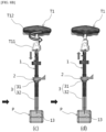
- FIGS. 7A and 7B are views for describing a surgical method using the surgical robot with the medical screw surgical device according to the first embodiment of the disclosure, FIG. 7A showing a perspective view (a) and a cross-section view (b) in which the firing member of the medical screw surgical device is moved down to hold the guide member, and FIG. 7B showing cross-sectional views in which the firing member of the medical screw surgical device is moved up with (a) no loads of the guide member as the firming member is lifted (as much as height H) and (b) a lifted state of the guide member.
- FIGS. 8A to 8C are perspective views for describing the surgical method using the surgical robot with the medical screw surgical device according to the first embodiment of the disclosure, in which the surgical processes are schematically shown in sequence.
- the surgical-device mounting step refers to a step of mounting the support arm 2 to the robot arm of the surgical robot, operating the robot arm to be in position on a surgical site, using the sleeve holder 31 to couple the sleeve 32 to the support arm 2, connecting the operation tool T1 as shown in (a) of FIG. 8A to the medical screw surgical device 1 assembled as shown in FIG. 2 , and inserting the medical screw surgical device 1 in the sleeve 32 as shown in (b) of FIG. 8A .
- the guide-member inserting step refers to a step of moving the guide member 13 down in position by controlling the moving piece 143 of the firing member 14 in a forward direction, i.e. in a downward direction as shown in FIGS. 7A and 8B , and inserting the guide member 13 into the surgical site by applying an operational force to the operation tool.
- the extension-member inserting step refers to a step of applying the tightening force to the operation tool T1 so that the extension member 12 can ream and tap the surgical site and form the screw insertion hole P2, in which, when the operation tool T1 is rotated clockwise as shown in (e) of FIG. 8C , the right-handed screw portion 122 of the extension member 12 burrows into and is inserted in the pedicle at a preset depth, thereby reaming and tapping the screw insertion hole.
- the guide member 13 not only has no-load condition based on the guide-member releasing step but also is formed with the left-handed screw portion 132, and is therefore not unintentionally inserted in the pedicle any more even while the operation tool T1 is rotated clockwise, thereby entering a state as shown in (b) of FIG. 7B .
- the medical-screw inserting step refers to a step of removing the operation tool T1 including the foregoing medical screw surgical device 1, inserting and fastening the screw coupling tool T2 (typically called the screw driver) with the medical screw S through the sleeve 332 of the surgical device holding member 3, and removing the screw coupling tool T2 when the medical screw S is completely inserted.
- the screw coupling tool T2 typically called the screw driver
- the surgery is performed by the concise and simple steps including the surgical-device mounting step, the guide-member inserting step, the guide-member releasing step, the extension-member inserting step and the medical-screw inserting step.
Landscapes
- Health & Medical Sciences (AREA)
- Life Sciences & Earth Sciences (AREA)
- Surgery (AREA)
- Orthopedic Medicine & Surgery (AREA)
- Engineering & Computer Science (AREA)
- Heart & Thoracic Surgery (AREA)
- General Health & Medical Sciences (AREA)
- Biomedical Technology (AREA)
- Veterinary Medicine (AREA)
- Medical Informatics (AREA)
- Molecular Biology (AREA)
- Animal Behavior & Ethology (AREA)
- Nuclear Medicine, Radiotherapy & Molecular Imaging (AREA)
- Public Health (AREA)
- Neurology (AREA)
- Dentistry (AREA)
- Oral & Maxillofacial Surgery (AREA)
- Robotics (AREA)
- Surgical Instruments (AREA)
Claims (8)
- Chirurgische medizinische Schraubenvorrichtung (1), die folgende Merkmale aufweist:einen Hauptkörper (11) der chirurgischen Vorrichtung, der einen stabförmigen Körper (111) mit einem darin gebildeten Einführdurchgang (112) aufweist;ein Verlängerungselement (12), das in einem unteren Abschnitt des Hauptkörpers (11) der chirurgischen Vorrichtung vorgesehen ist und ein darin gebildetes Führungsloch (123) aufweist, wobei das Verlängerungselement einen stiftförmigen Verlängerungselementkörper aufweist, wobei das Führungselement (13) einen stiftförmigen Führungskörper (131) aufweist;ein Führungselement (13), das beweglich in dem Führungsloch (123) des Verlängerungselements (12) vorgesehen ist; undein Auslöseelement (14), das in dem Einführdurchgang (112) des Hauptkörpers (11) der chirurgischen Vorrichtung vorgesehen ist und das Führungselement (13) so steuert, dass es sich auf und ab bewegt,dadurch gekennzeichnet, dass das Führungselement (13) einen Schraubenabschnitt aufweist, der an einer Außenumfangsoberfläche des Führungskörpers (131) gebildet ist, unddas Verlängerungselement (12) einen Schraubenabschnitt aufweist, der an einer Außenumfangsoberfläche des Verlängerungselementkörpers gebildet ist, der ein Gewinde (122) mit einer Gewinderichtung entgegengesetzt zu der Gewinderichtung des Schraubenabschnitts des Führungselements (13) aufweist.
- Chirurgische medizinische Schraubenvorrichtung (1) gemäß Anspruch 1, die ferner ein Werkzeugverbindungselement (15) aufweist, das in einem oberen Abschnitt des Hauptkörpers (11) der chirurgischen Vorrichtung vorgesehen ist und mit einem Betätigungswerkzeug (T1) verbunden ist, zum Anwenden einer Anziehkraft und einer Lösekraft auf den Hauptkörper (11) der chirurgischen Vorrichtung.
- Chirurgische medizinische Schraubenvorrichtung (1) gemäß Anspruch 2, bei derdas Werkzeugverbindungselement (15) einen Verbindungskörper (151) und einen Fixierungsbolzen (152) aufweist, wobei der Verbindungskörper (151) einen Hauptkörperverbinder (1511), der in einen oberen Abschnitt des Hauptkörpers (11) der chirurgischen Vorrichtung eingeführt ist und mit einem Fixierungsbolzen-Einführloch (115) gebildet ist, und einen Werkzeugverbinder (1512) aufweist, mit dem das Betätigungswerkzeug (T1) verbunden ist, und wobei der Fixierungsbolzen (152) in das Fixierungsbolzen-Einführloch (115) des Verbindungskörpers (151) eingeführt ist, undder Hauptkörper (11) der chirurgischen Vorrichtung ein Fixierungsbolzen-Befestigungsloch (115) in einem oberen Abschnitt desselben aufweist, an dem der Fixierungsbolzen (152) befestigt ist.
- Chirurgische medizinische Schraubenvorrichtung gemäß Anspruch 1, bei derdas Führungselement (13) einen Anschlagvorsprung (133) aufweist, der in einem oberen Abschnitt des Führungskörpers (131) gebildet ist, unddas Verlängerungselement (12) ein Vorsprung-Bewegungsloch (124) aufweist, das so gebildet ist, dass es einen Querschnitt aufweist, der einem Querschnitt des Anschlagvorsprungs (133) entspricht und mit dem Führungsloch (123) in Verbindung steht.
- Chirurgische medizinische Schraubenvorrichtung (1) gemäß Anspruch 1, bei derdas Verlängerungselement (12) einen aufgeschnittenen Abschnitt aufweist, der einen Höhenunterschied an der Außenumfangsoberfläche des Verlängerungselementkörpers (121) aufweist, undder Einführdurchgang (112) des Hauptkörpers (11) der chirurgischen Vorrichtung mit einem Einführloch (113) des aufgeschnittenen Abschnitts gebildet ist, in das der aufgeschnittene Abschnitt eingeführt ist und in dem er sitzt.
- Chirurgische medizinische Schraubenvorrichtung (1) gemäß Anspruch 1, bei derdas Auslöseelement (14) einen Auslöseelementkörper (141), der wie eine Stange geformt ist, eine Stützstange (142), die von einem unteren Abschnitt des Auslöseelementkörpers (141) vorsteht und mit dem oberen Abschnitt des Führungselements (13) in Kontakt ist, und ein bewegliches Stück aufweist, das in einem oberen Abschnitt des Auslöseelementkörpers (141) gebildet ist, undeine Bewegungsführungsrille (143), die es dem beweglichen Stück ermöglicht, sich auf und ab zu bewegen, und Halterillen, die mit der Bewegungsführungsrille in Verbindung stehen und das bewegliche Stück in Position halten, so gebildet sind, dass sie mit dem Einführdurchgang des Hauptkörpers (11) der chirurgischen Vorrichtung in Verbindung stehen.
- Chirurgischer Roboter mit einem Roboterarm, der folgende Merkmale aufweist:einen Stützarm (2), der in dem Roboterarm vorgesehen ist;ein Halteelement (3) der chirurgischen Vorrichtung, das in dem Stützarm (2) vorgesehen ist; unddie chirurgische medizinische Schraubenvorrichtung (1) gemäß einem der Ansprüche 1 bis 6, die in dem Halteelement (3) der chirurgischen Vorrichtung vorgesehen ist.
- Chirurgischer Roboter gemäß Anspruch 7, bei demder Stützarm (2) so strukturiert ist, dass er ein Kopplungsloch (22) an einem Endabschnitt des Stützarmkörpers (21) aufweist, der einen gekrümmten Abschnitt aufweist, unddas Halteelement (3) der chirurgischen Vorrichtung einen Hülsenhalter (31), der in das Kopplungsloch (22) eingeführt und mit diesem verriegelt ist und mit einem Hülseneinführloch (312) gebildet ist, und eine Hülse (32) aufweist, die in den Hülsenhalter (31) eingeführt ist und ein Einführloch der chirurgischen Vorrichtung aufweist.
Applications Claiming Priority (2)
| Application Number | Priority Date | Filing Date | Title |
|---|---|---|---|
| KR1020180017938A KR102086690B1 (ko) | 2018-02-13 | 2018-02-13 | 의료용스크류 수술장치, 이를 구비한 수술로봇 및 의료용스크류 수술장치를 구비한 수술로봇을 이용한 수술방법 |
| PCT/KR2019/001664 WO2019160291A1 (ko) | 2018-02-13 | 2019-02-12 | 의료용스크류 수술장치, 이를 구비한 수술로봇 및 의료용스크류 수술장치를 구비한 수술로봇을 이용한 수술방법 |
Publications (4)
| Publication Number | Publication Date |
|---|---|
| EP3753514A1 EP3753514A1 (de) | 2020-12-23 |
| EP3753514A4 EP3753514A4 (de) | 2021-11-17 |
| EP3753514B1 true EP3753514B1 (de) | 2024-11-20 |
| EP3753514C0 EP3753514C0 (de) | 2024-11-20 |
Family
ID=67619829
Family Applications (1)
| Application Number | Title | Priority Date | Filing Date |
|---|---|---|---|
| EP19754459.6A Active EP3753514B1 (de) | 2018-02-13 | 2019-02-12 | Medizinische schraubenoperationsvorrichtung und operationsroboter damit |
Country Status (7)
| Country | Link |
|---|---|
| US (1) | US11849959B2 (de) |
| EP (1) | EP3753514B1 (de) |
| JP (1) | JP7052084B2 (de) |
| KR (1) | KR102086690B1 (de) |
| CN (1) | CN111818871B (de) |
| ES (1) | ES3001443T3 (de) |
| WO (1) | WO2019160291A1 (de) |
Families Citing this family (1)
| Publication number | Priority date | Publication date | Assignee | Title |
|---|---|---|---|---|
| EP4088674B1 (de) * | 2021-05-12 | 2023-11-29 | Biedermann Technologies GmbH & Co. KG | Instrument zur verwendung in der chirurgie |
Family Cites Families (30)
| Publication number | Priority date | Publication date | Assignee | Title |
|---|---|---|---|---|
| US4979949A (en) * | 1988-04-26 | 1990-12-25 | The Board Of Regents Of The University Of Washington | Robot-aided system for surgery |
| US6287313B1 (en) * | 1999-11-23 | 2001-09-11 | Sdgi Holdings, Inc. | Screw delivery system and method |
| US9539012B2 (en) * | 2002-10-30 | 2017-01-10 | Zimmer Spine, Inc. | Spinal stabilization systems with quick-connect sleeve assemblies for use in surgical procedures |
| CN2617324Y (zh) * | 2003-04-14 | 2004-05-26 | 王伟 | 经皮穿刺脊柱内固定器 |
| CN1268297C (zh) * | 2003-12-17 | 2006-08-09 | 尹庆水 | 寰枢椎复位器 |
| US7491207B2 (en) * | 2004-04-12 | 2009-02-17 | Synthes Usa, Llc | Rod persuader |
| US20060079903A1 (en) * | 2004-10-08 | 2006-04-13 | Wong David A | Minimally invasive pedicle screw and guide support |
| CA2816973C (en) | 2005-03-07 | 2014-11-04 | Hector O. Pacheco | Cannula for insertion in the elongated opening of a pedicle |
| US7704257B2 (en) * | 2005-11-23 | 2010-04-27 | Stryker Trauma S.A. | Compression instrument |
| EP1991153A4 (de) | 2006-02-17 | 2010-07-21 | Young Wan Song | Implantat-bohrer |
| US8167899B2 (en) | 2006-05-04 | 2012-05-01 | Warsaw Orthopedic, Inc. | Retractable stylet and cannula combination |
| US8814880B2 (en) * | 2006-12-28 | 2014-08-26 | Craig M. McAllister | Device and method for mounting an object on a bone |
| US8029523B2 (en) | 2007-03-30 | 2011-10-04 | Innovative Implant Technology, Llc | Maxillary bone cutting system, kit, and method of using the same |
| US20090275954A1 (en) * | 2008-04-30 | 2009-11-05 | Phan Christopher U | Apparatus and methods for inserting facet screws |
| US20100211115A1 (en) * | 2008-12-24 | 2010-08-19 | Jeff Tyber | Compression screw assembly, an orthopedic fixation system including a compression screw assembly and method of use |
| KR101001539B1 (ko) | 2010-06-14 | 2010-12-17 | 주식회사 디오메디칼 | 척추교정용 로드 삽입기구 및 이를 구비한 척추교정 시술장치 |
| US10874466B2 (en) * | 2012-06-21 | 2020-12-29 | Globus Medical, Inc. | System and method for surgical tool insertion using multiaxis force and moment feedback |
| CN202920793U (zh) * | 2012-07-04 | 2013-05-08 | 张强 | 微创骨折固定逐级扩张套筒器 |
| US9433445B2 (en) | 2013-03-14 | 2016-09-06 | DePuy Synthes Products, Inc. | Bone anchors and surgical instruments with integrated guide tips |
| KR101631908B1 (ko) | 2014-03-03 | 2016-06-20 | 유앤아이 주식회사 | 척추경에 스크류를 고정하기 위한 수술방법 및 상기 방법에 사용되는 스크류의 삽입 도구 |
| CN103948426B (zh) * | 2014-04-15 | 2016-04-06 | 首都医科大学附属北京友谊医院 | 经双侧椎弓根手术套管组合器械 |
| WO2015162256A1 (en) * | 2014-04-24 | 2015-10-29 | KB Medical SA | Surgical instrument holder for use with a robotic surgical system |
| KR101630794B1 (ko) * | 2014-07-02 | 2016-06-15 | (주)미래컴퍼니 | 수술 로봇 시스템 및 이에 구비되는 액티브 가이드 유닛 |
| US10603094B2 (en) * | 2015-03-31 | 2020-03-31 | Depuy Ireland Unlimited Company | System and method for attaching a surgical instrument to a patient's bone |
| KR20160133191A (ko) * | 2015-05-12 | 2016-11-22 | 현대중공업 주식회사 | 이송용 보조로봇 |
| DE102015223479B4 (de) * | 2015-11-26 | 2017-07-27 | Silony Medical International AG | Handhabungsinstrument für eine Knochenschraube |
| GB2551581A (en) * | 2016-06-24 | 2017-12-27 | Johannes Hoogland Jaap | Surgical drill for cutting bone |
| WO2018013536A2 (en) * | 2016-07-12 | 2018-01-18 | Gys Tech Llc D/B/A Cardan Robotics | Multi-stage dilator and cannula system and method |
| CN106691600A (zh) * | 2016-11-21 | 2017-05-24 | 胡磊 | 一种脊柱椎弓根钉植入定位装置 |
| EP3351202B1 (de) * | 2017-01-18 | 2021-09-08 | KB Medical SA | Universelle instrumentenführung für chirurgische robotersysteme |
-
2018
- 2018-02-13 KR KR1020180017938A patent/KR102086690B1/ko active Active
-
2019
- 2019-02-12 WO PCT/KR2019/001664 patent/WO2019160291A1/ko not_active Ceased
- 2019-02-12 ES ES19754459T patent/ES3001443T3/es active Active
- 2019-02-12 EP EP19754459.6A patent/EP3753514B1/de active Active
- 2019-02-12 US US16/965,207 patent/US11849959B2/en active Active
- 2019-02-12 CN CN201980012215.6A patent/CN111818871B/zh active Active
- 2019-02-12 JP JP2020563885A patent/JP7052084B2/ja active Active
Also Published As
| Publication number | Publication date |
|---|---|
| ES3001443T3 (en) | 2025-03-05 |
| CN111818871B (zh) | 2022-08-26 |
| WO2019160291A1 (ko) | 2019-08-22 |
| US20210059692A1 (en) | 2021-03-04 |
| JP7052084B2 (ja) | 2022-04-11 |
| CN111818871A (zh) | 2020-10-23 |
| EP3753514C0 (de) | 2024-11-20 |
| EP3753514A4 (de) | 2021-11-17 |
| KR20190097922A (ko) | 2019-08-21 |
| JP2021514277A (ja) | 2021-06-10 |
| US11849959B2 (en) | 2023-12-26 |
| KR102086690B1 (ko) | 2020-03-10 |
| EP3753514A1 (de) | 2020-12-23 |
Similar Documents
| Publication | Publication Date | Title |
|---|---|---|
| US12070251B2 (en) | Systems and methods for spinal rod insertion and reduction | |
| JP4320263B2 (ja) | ロッド押込み具 | |
| JP4965856B2 (ja) | 可変オフセットコネクタおよび骨固定方法 | |
| US10219838B2 (en) | Pedicle screw fixation system and method for use of same | |
| US7588588B2 (en) | System and method for stabilizing of internal structures | |
| US9788869B2 (en) | Spinal fixation element rotation instrument | |
| CA2198268C (en) | Plate holding drill guide and trocar and method of holding a plate | |
| US20140074106A1 (en) | Working tower, rod inserter, rod reducer, and compression-distraction tool for minimally invasive surgery system | |
| US20080312703A1 (en) | Instrumentation and associated techniques for minimally invasive vertebral rod installation | |
| EP0617927A1 (de) | Chirurgische Vorrichtung zur Verbindung von Knochenbrüchen | |
| JP2011072772A (ja) | ロッドホルダー及びこれを利用する脊椎用最小侵襲手術システム | |
| CN1972637A (zh) | 杆强制工具 | |
| JP2010227573A (ja) | 固定化システムを脊柱に挿入する器具セット | |
| CN101938948A (zh) | 骨盆缆线解决方案 | |
| KR100936212B1 (ko) | 척추고정시스템의 로드 장착장치 | |
| EP3753514B1 (de) | Medizinische schraubenoperationsvorrichtung und operationsroboter damit | |
| JP2007508118A (ja) | 脊椎固定フックおよび脊椎固定方法 | |
| JP2022527837A (ja) | 多軸外科用ねじおよび当該外科用ねじを埋め込むための装置 | |
| KR20120001959A (ko) | 스크류 홀더 |
Legal Events
| Date | Code | Title | Description |
|---|---|---|---|
| STAA | Information on the status of an ep patent application or granted ep patent |
Free format text: STATUS: THE INTERNATIONAL PUBLICATION HAS BEEN MADE |
|
| PUAI | Public reference made under article 153(3) epc to a published international application that has entered the european phase |
Free format text: ORIGINAL CODE: 0009012 |
|
| STAA | Information on the status of an ep patent application or granted ep patent |
Free format text: STATUS: REQUEST FOR EXAMINATION WAS MADE |
|
| 17P | Request for examination filed |
Effective date: 20200807 |
|
| AK | Designated contracting states |
Kind code of ref document: A1 Designated state(s): AL AT BE BG CH CY CZ DE DK EE ES FI FR GB GR HR HU IE IS IT LI LT LU LV MC MK MT NL NO PL PT RO RS SE SI SK SM TR |
|
| AX | Request for extension of the european patent |
Extension state: BA ME |
|
| DAV | Request for validation of the european patent (deleted) | ||
| DAX | Request for extension of the european patent (deleted) | ||
| A4 | Supplementary search report drawn up and despatched |
Effective date: 20211018 |
|
| RIC1 | Information provided on ipc code assigned before grant |
Ipc: A61B 17/70 20060101ALI20211012BHEP Ipc: A61B 17/90 20060101ALI20211012BHEP Ipc: A61B 17/17 20060101ALI20211012BHEP Ipc: A61B 34/00 20160101ALI20211012BHEP Ipc: A61B 34/30 20160101ALI20211012BHEP Ipc: A61B 17/88 20060101ALI20211012BHEP Ipc: A61B 17/86 20060101AFI20211012BHEP |
|
| GRAP | Despatch of communication of intention to grant a patent |
Free format text: ORIGINAL CODE: EPIDOSNIGR1 |
|
| STAA | Information on the status of an ep patent application or granted ep patent |
Free format text: STATUS: GRANT OF PATENT IS INTENDED |
|
| INTG | Intention to grant announced |
Effective date: 20240112 |
|
| GRAJ | Information related to disapproval of communication of intention to grant by the applicant or resumption of examination proceedings by the epo deleted |
Free format text: ORIGINAL CODE: EPIDOSDIGR1 |
|
| STAA | Information on the status of an ep patent application or granted ep patent |
Free format text: STATUS: REQUEST FOR EXAMINATION WAS MADE |
|
| INTC | Intention to grant announced (deleted) | ||
| GRAP | Despatch of communication of intention to grant a patent |
Free format text: ORIGINAL CODE: EPIDOSNIGR1 |
|
| STAA | Information on the status of an ep patent application or granted ep patent |
Free format text: STATUS: GRANT OF PATENT IS INTENDED |
|
| INTG | Intention to grant announced |
Effective date: 20240610 |
|
| GRAS | Grant fee paid |
Free format text: ORIGINAL CODE: EPIDOSNIGR3 |
|
| GRAA | (expected) grant |
Free format text: ORIGINAL CODE: 0009210 |
|
| STAA | Information on the status of an ep patent application or granted ep patent |
Free format text: STATUS: THE PATENT HAS BEEN GRANTED |
|
| RAP3 | Party data changed (applicant data changed or rights of an application transferred) |
Owner name: INDUSTRY-ACADEMIC COOPERATION FOUNDATIONYONSEI UNIVERSITY Owner name: CUREXO, INC. |
|
| AK | Designated contracting states |
Kind code of ref document: B1 Designated state(s): AL AT BE BG CH CY CZ DE DK EE ES FI FR GB GR HR HU IE IS IT LI LT LU LV MC MK MT NL NO PL PT RO RS SE SI SK SM TR |
|
| REG | Reference to a national code |
Ref country code: GB Ref legal event code: FG4D |
|
| REG | Reference to a national code |
Ref country code: CH Ref legal event code: EP |
|
| REG | Reference to a national code |
Ref country code: DE Ref legal event code: R096 Ref document number: 602019062245 Country of ref document: DE |
|
| REG | Reference to a national code |
Ref country code: IE Ref legal event code: FG4D |
|
| U01 | Request for unitary effect filed |
Effective date: 20241217 |
|
| U07 | Unitary effect registered |
Designated state(s): AT BE BG DE DK EE FI FR IT LT LU LV MT NL PT RO SE SI Effective date: 20250102 |
|
| U20 | Renewal fee for the european patent with unitary effect paid |
Year of fee payment: 7 Effective date: 20250220 |
|
| PG25 | Lapsed in a contracting state [announced via postgrant information from national office to epo] |
Ref country code: IS Free format text: LAPSE BECAUSE OF FAILURE TO SUBMIT A TRANSLATION OF THE DESCRIPTION OR TO PAY THE FEE WITHIN THE PRESCRIBED TIME-LIMIT Effective date: 20250320 Ref country code: HR Free format text: LAPSE BECAUSE OF FAILURE TO SUBMIT A TRANSLATION OF THE DESCRIPTION OR TO PAY THE FEE WITHIN THE PRESCRIBED TIME-LIMIT Effective date: 20241120 |
|
| PGFP | Annual fee paid to national office [announced via postgrant information from national office to epo] |
Ref country code: ES Payment date: 20250303 Year of fee payment: 7 |
|
| PGFP | Annual fee paid to national office [announced via postgrant information from national office to epo] |
Ref country code: IE Payment date: 20250221 Year of fee payment: 7 |
|
| PG25 | Lapsed in a contracting state [announced via postgrant information from national office to epo] |
Ref country code: NO Free format text: LAPSE BECAUSE OF FAILURE TO SUBMIT A TRANSLATION OF THE DESCRIPTION OR TO PAY THE FEE WITHIN THE PRESCRIBED TIME-LIMIT Effective date: 20250220 |
|
| PGFP | Annual fee paid to national office [announced via postgrant information from national office to epo] |
Ref country code: GR Payment date: 20250225 Year of fee payment: 7 |
|
| PG25 | Lapsed in a contracting state [announced via postgrant information from national office to epo] |
Ref country code: PL Free format text: LAPSE BECAUSE OF FAILURE TO SUBMIT A TRANSLATION OF THE DESCRIPTION OR TO PAY THE FEE WITHIN THE PRESCRIBED TIME-LIMIT Effective date: 20241120 |
|
| PGFP | Annual fee paid to national office [announced via postgrant information from national office to epo] |
Ref country code: GB Payment date: 20250218 Year of fee payment: 7 |
|
| PG25 | Lapsed in a contracting state [announced via postgrant information from national office to epo] |
Ref country code: RS Free format text: LAPSE BECAUSE OF FAILURE TO SUBMIT A TRANSLATION OF THE DESCRIPTION OR TO PAY THE FEE WITHIN THE PRESCRIBED TIME-LIMIT Effective date: 20250220 |
|
| REG | Reference to a national code |
Ref country code: GR Ref legal event code: EP Ref document number: 20250400368 Country of ref document: GR Effective date: 20250409 |
|
| PG25 | Lapsed in a contracting state [announced via postgrant information from national office to epo] |
Ref country code: SM Free format text: LAPSE BECAUSE OF FAILURE TO SUBMIT A TRANSLATION OF THE DESCRIPTION OR TO PAY THE FEE WITHIN THE PRESCRIBED TIME-LIMIT Effective date: 20241120 |
|
| PG25 | Lapsed in a contracting state [announced via postgrant information from national office to epo] |
Ref country code: SK Free format text: LAPSE BECAUSE OF FAILURE TO SUBMIT A TRANSLATION OF THE DESCRIPTION OR TO PAY THE FEE WITHIN THE PRESCRIBED TIME-LIMIT Effective date: 20241120 |
|
| PG25 | Lapsed in a contracting state [announced via postgrant information from national office to epo] |
Ref country code: CZ Free format text: LAPSE BECAUSE OF FAILURE TO SUBMIT A TRANSLATION OF THE DESCRIPTION OR TO PAY THE FEE WITHIN THE PRESCRIBED TIME-LIMIT Effective date: 20241120 |
|
| PG25 | Lapsed in a contracting state [announced via postgrant information from national office to epo] |
Ref country code: MC Free format text: LAPSE BECAUSE OF FAILURE TO SUBMIT A TRANSLATION OF THE DESCRIPTION OR TO PAY THE FEE WITHIN THE PRESCRIBED TIME-LIMIT Effective date: 20241120 |
|
| PLBE | No opposition filed within time limit |
Free format text: ORIGINAL CODE: 0009261 |
|
| STAA | Information on the status of an ep patent application or granted ep patent |
Free format text: STATUS: NO OPPOSITION FILED WITHIN TIME LIMIT |
|
| REG | Reference to a national code |
Ref country code: CH Ref legal event code: PL |
|
| PG25 | Lapsed in a contracting state [announced via postgrant information from national office to epo] |
Ref country code: CH Free format text: LAPSE BECAUSE OF NON-PAYMENT OF DUE FEES Effective date: 20250228 |
|
| 26N | No opposition filed |
Effective date: 20250821 |