EP3752799B1 - Messstab und elektronischer füllstandssensor - Google Patents
Messstab und elektronischer füllstandssensor Download PDFInfo
- Publication number
- EP3752799B1 EP3752799B1 EP19754275.6A EP19754275A EP3752799B1 EP 3752799 B1 EP3752799 B1 EP 3752799B1 EP 19754275 A EP19754275 A EP 19754275A EP 3752799 B1 EP3752799 B1 EP 3752799B1
- Authority
- EP
- European Patent Office
- Prior art keywords
- dipstick
- fluid
- electrically conductive
- level
- electrical
- Prior art date
- Legal status (The legal status is an assumption and is not a legal conclusion. Google has not performed a legal analysis and makes no representation as to the accuracy of the status listed.)
- Active
Links
Images




Classifications
-
- G—PHYSICS
- G01—MEASURING; TESTING
- G01F—MEASURING VOLUME, VOLUME FLOW, MASS FLOW OR LIQUID LEVEL; METERING BY VOLUME
- G01F23/00—Indicating or measuring liquid level or level of fluent solid material, e.g. indicating in terms of volume or indicating by means of an alarm
- G01F23/04—Indicating or measuring liquid level or level of fluent solid material, e.g. indicating in terms of volume or indicating by means of an alarm by dip members, e.g. dip-sticks
-
- F—MECHANICAL ENGINEERING; LIGHTING; HEATING; WEAPONS; BLASTING
- F01—MACHINES OR ENGINES IN GENERAL; ENGINE PLANTS IN GENERAL; STEAM ENGINES
- F01M—LUBRICATING OF MACHINES OR ENGINES IN GENERAL; LUBRICATING INTERNAL COMBUSTION ENGINES; CRANKCASE VENTILATING
- F01M11/00—Component parts, details or accessories, not provided for in, or of interest apart from, groups F01M1/00 - F01M9/00
- F01M11/10—Indicating devices; Other safety devices
- F01M11/12—Indicating devices; Other safety devices concerning lubricant level
-
- G—PHYSICS
- G01—MEASURING; TESTING
- G01F—MEASURING VOLUME, VOLUME FLOW, MASS FLOW OR LIQUID LEVEL; METERING BY VOLUME
- G01F23/00—Indicating or measuring liquid level or level of fluent solid material, e.g. indicating in terms of volume or indicating by means of an alarm
- G01F23/22—Indicating or measuring liquid level or level of fluent solid material, e.g. indicating in terms of volume or indicating by means of an alarm by measuring physical variables, other than linear dimensions, pressure or weight, dependent on the level to be measured, e.g. by difference of heat transfer of steam or water
- G01F23/26—Indicating or measuring liquid level or level of fluent solid material, e.g. indicating in terms of volume or indicating by means of an alarm by measuring physical variables, other than linear dimensions, pressure or weight, dependent on the level to be measured, e.g. by difference of heat transfer of steam or water by measuring variations of capacity or inductance of capacitors or inductors arising from the presence of liquid or fluent solid material in the electric or electromagnetic fields
-
- G—PHYSICS
- G01—MEASURING; TESTING
- G01F—MEASURING VOLUME, VOLUME FLOW, MASS FLOW OR LIQUID LEVEL; METERING BY VOLUME
- G01F23/00—Indicating or measuring liquid level or level of fluent solid material, e.g. indicating in terms of volume or indicating by means of an alarm
- G01F23/22—Indicating or measuring liquid level or level of fluent solid material, e.g. indicating in terms of volume or indicating by means of an alarm by measuring physical variables, other than linear dimensions, pressure or weight, dependent on the level to be measured, e.g. by difference of heat transfer of steam or water
- G01F23/26—Indicating or measuring liquid level or level of fluent solid material, e.g. indicating in terms of volume or indicating by means of an alarm by measuring physical variables, other than linear dimensions, pressure or weight, dependent on the level to be measured, e.g. by difference of heat transfer of steam or water by measuring variations of capacity or inductance of capacitors or inductors arising from the presence of liquid or fluent solid material in the electric or electromagnetic fields
- G01F23/263—Indicating or measuring liquid level or level of fluent solid material, e.g. indicating in terms of volume or indicating by means of an alarm by measuring physical variables, other than linear dimensions, pressure or weight, dependent on the level to be measured, e.g. by difference of heat transfer of steam or water by measuring variations of capacity or inductance of capacitors or inductors arising from the presence of liquid or fluent solid material in the electric or electromagnetic fields by measuring variations in capacitance of capacitors
Definitions
- This invention relates to systems for determining the depth of fluid in a reservoir, and more particularly to determining the depth of fluid using a dipstick and an electronic sensing system. It is particularly applicable to systems for electronically monitoring the depth of oil in the crankcase of an engine where a dipstick is also provided for manual checking of the depth of the fluid.
- a dipstick for checking the level of oil present in the engine crankcase using a dipstick that is secured extending into the crankcase.
- the level is checked by cleaning the dipstick and inserting it into a passage in the crankcase and then withdrawing it.
- the oil level of the engine may be immediately determined by looking at the height of oil clingage to the dipstick, which may have markings to indicate the amount of oil associated with the depth of oil.
- FR2936313A1 shows a dipstick equipped with a transducer as sensor to measure the oil level.
- the oil level measured by the sensor depends on the position of the transducer and may vary with the insertion position and/or rotation of the dipstick. Due to the length of the dipstick and the positioning of the transducers, physical contact between the oil containing vessel and the transducers cannot be excluded during operation, which also interferes with correct measurement results.
- a system comprises a reservoir containing liquid that extends up to a level of the fluid, and a dipstick support structure supporting a dipstick on it so that the dipstick extends into the fluid past the level of the fluid, and so that the dipstick is manually removable from the dipstick support structure by a user.
- An electrical system is connected with the dipstick, and the electrical system electrically senses the level of the fluid based on an electrical characteristic of the dipstick that varies with the varying level of the fluid when the dipstick extends therein.
- the reservoir is an engine crankcase containing oil or a fluid mixed with oil, the level of which is detected using a dipstick configured for use in an electronic fluid-level sensor system.
- a method for sensing liquid in a reservoir, especially oil in an engine crankcase.
- the method comprises providing a dipstick removably supported so as to extend into the reservoir and into the liquid in an installed position.
- the dipstick has markings on it that indicate the level of the fluid on visual inspection by a user when the dipstick is removed from the reservoir.
- An electrical property of the dipstick is electrically detected when the dipstick is placed in the reservoir in the installed position so as to produce an electrical output indicative of the level of the fluid.
- a comparison of the level of the fluid to a predetermined level is performed electrically, and an alert is output to the user responsive to the comparison indicating that the level of the fluid is below the predetermined level.
- the method detects capacitance of the dipstick relative to the reservoir.
- the detecting of the capacitance comprises repeatedly applying an electrical current to the dipstick until the dipstick is charged, and then cutting the electrical current to the dipstick until the dipstick discharges. This is used to generate an output signal from the repeated charging and discharging that is a waveform with a frequency that is correlated to the level of fluid into which the dipstick extends in the installed position.
- a use of said system is provided for retrofitting an engine with an electronic liquid or oil level sensor.
- changing capacitance is used to measure a fluid level based on frequency as an output from the sensor circuit in which a manual dipstick with minor modifications is part of the capacitive fluid level sensing circuit for both remote and manual level checking.
- the present invention combines the utility of checking liquid levels using a traditional dipstick with the modern convenience of an electronic reporting sensor.
- the combination of the methods provides redundant operation in case of electronic failure and a traditional method of checking fluid levels for maintainers of the equipment.
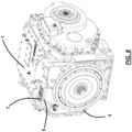
- FIG. 8 shows a transmission 1 used for a vehicle, comprising a block with a sump 3 that is filled with lubricating liquid, usually real or synthetic oil.
- An access structure 5 supports a dipstick structure 7 in it that can be removed, and clingage of oil to the dipstick can be viewed to see the level of oil in the crankcase 3.
- the access structure 5 is an opening that, in some cases, also is configured to be an opening for pouring oil into the crankcase.
- the dipstick 7 is supported by structure that has an access structure 9 extending through the housing wall from the exterior where it meets an enlarged perforated tube 11 that at its lower end 10 is connected with an elongated dipstick tube 13 that extends generally to the bottom of the sump 3.
- the tube 13 is open at both ends so it fills up with oil or whatever liquid in the reservoir to the same level as outside of the tube 13. Liquids are allowed to pass through the upper and lower housings or tubes 11 and 13 to the sump, allowing the maintenance personnel to add fluid at any time by removing the dipstick assembly.
- the holes in the perforated tube 11 allow for oil to be added to the crankcase 3 through tube 11.
- a dipstick 15 is fixedly attached to the outer dipstick handle 7, which is removably sealed into the access structure 9 so as to seal off the access when secured in place.
- the dipstick extends from the handle 7 through the dipstick receiving structure, i.e., tubes 11 and 13 to a distal end 17.
- the dipstick 15 is a flat ribbon-like structure comprising a metal interior 19 surrounded by an outer layer 21 of electrically-nonconductive material.
- the interior metal is any sort of conductive metal or other conductive material that is adequately rigid to perform the function of a dipstick, e.g., stainless steel.
- the outer layer or coating 21 is preferably of an electrically non-conductive plastic polymer material that is durable and heat resistant, such as polyimide material, with a thickness sufficient to prevent flow of electrical power at a working voltage of the dipstick sensor, e.g., 5 volts.
- the dipstick 15 functions in traditional manner, in that it may be removed, and a level of fluid in the sump may be checked by a user visually examining the clingage to the outer surface of the dipstick, which may be provided with markings at locations along the length of the dipstick where it contacts fluid when inserted into the housing to show amounts of liquid corresponding to the level of clingage on the dipstick.
- the dipstick 15 also functions as one side of capacitive sensor pair.
- the polymer coating 21 prevents the metal or steel interior 19 of the dipstick from touching the guide tube 13 along its curved path. As the oil level inside the sump changes over time, the capacitance between the dipstick steel or metal core 19 and the guide housing 13 changes as well.
- the guide tube 13 reduces measured oil error due to foaming.
- the dipstick sensor device is configured to be mounted by inserting a two-part cylindrical structure generally indicated at 22 into a machined pocket or a bore in and extending through the wall 25 of the exterior of the transmission housing 27 (shown in phantom) where the conventional dipstick system would extend. As best seen in FIG. 3 , in the embodiment shown, the dipstick sensor device is configured to be mounted by inserting a two-part cylindrical structure generally indicated at 22 into a machined pocket or a bore in and extending through the wall 25 of the exterior of the transmission housing 27 (shown in phantom) where the conventional dipstick system would extend. As best seen in FIG.
- the manual dipstick bore in wall 25, shown in phantom normally has an outer cylindrical passage that narrows radially to provide an annular shelf with a narrower concentric cylindrical bore therein extending into and communicating with the interior space of the housing 3
- the installation may be an original installation or a retro- fit in which the electrical level-sensing system is installed in a block in which only the standard mechanical user-viewed clingage assessment of fluid level is provided.
- the original mechanical system dipstick structure is removed to leave the bore, and the housings 23 and 24 are inserted therein.
- the two-part cylindrical structure 22 includes upper cylindrical housing 23 and lower cylindrical housing 24. These structures 22 and 23 are configured to be received snugly in the bore in the housing.
- the lower cylindrical housing 24 is sized to fit in and be secured fixedly in the upper wider part of the bore or passage through the wall 25 of the crankcase or transmission housing, resting on the annular shoulder of the dipstick bore.
- Lower housing 24 has electrical contacts connected to wires that extend inside the crankcase or housing to the electrical harness and control electronics circuitry of the vehicle. Those may need to be installed in the housing 3 in the case of a manual dipstick retrofit process. For example, a hole or passage may be drilled in the housing through which wiring from the dipstick sensor system extends, and sealing the passage so that fluid in the reservoir cannot escape therethrough and so that contaminants cannot enter the reservoir from the outside.
- the upper cylindrical housing 23 fits into the upper wider bore or passage in wall 25 and is secured in it by a screw 27 and washer on a bracket 28 on the side of the upper cylindrical housing 23 that releasably screws into a threaded bore (not shown) in the outer surface of wall 25 of the crankcase or transmission housing.
- An O-ring 29 mounted in a groove in the upper cylindrical housing 23 seals any gap in the bore in the wall 25 around the cylindrical housing 23 to keep contaminants out.
- the parts of the dipstick assembly are configured so that relatively low-cost, high- reliability components are mounted to the lower housing 24 and then connected to the wiring harness of the engine or transmission.
- the outer surface of the upper cylindrical housing 23 has a recess 31 therein that supports a circuit board strcuture 33 fixedly secured to the cylindrical housing 23 in the recess 31.
- the circuit board 33 has four electrical spring contacts 35 that each mate with and connect electrically to a corrsponding electrcial contact of a set of four plate or tongue contacts 37 supported on lower cylindrical housing 24 in the bore of the wall 25, and those contacts 35 connect to wires leading from the disptick sensor structure to electrical circuitry.
- the circuit board 33 and spring contacts 35 are more likely to fail over time than the contacts 37 and wires of the lower housing 24, and the circuit board 33 and spring contacts 35 therefore are mounted to the upper housing 23.
- the upper housing 23 is accessible from outside the engine or transmission exterior, and can be easily removed and repaired without interrupting the main wire harness.
- the dipstick structure 39 comprises a handle 7 extending from a cap 41 that is configured to fit over the outside upper end of the upper housing 23.
- the structure includes an elastomeric seal portion 43 and a Y-shaped support 45 that supports at its lower end the coated metal ribbon-shaped dipstick 15.
- the seal portion 43 is cylindrical and sized to fit into an internal cylindrical passage 46 extending through the upper and lower housings 22 and 24.
- the cap 41 when the dipstick is closed, the cap 41 overlies and covers the open top end of the upper housing 23.
- dipstick structure 39 The internal structure and operation of the dipstick structure 39 is best seen in FIGS. 5 and 6 .
- the dipstick 15 is connected mechanically and electrically to metallic Y-shaped support 45, which includes a collar plate 47.
- Collar plate 47 has downwardly extending contact arms 49 that engage and electrically connect with generally conical contact 5lsecured in the interior passage of upper cylindrical housing 23.
- Conical contact 51 is electrically connected with the circuit board 33. This arrangement electrically links the dipstick 15 to the circuitry 33.
- the structure also mechanically supports the disptick insulated from electrical contact bewteen the dipstick and any other part of the engine.
- the coating 21 insulates the ribbon- shaped part 19 from contact with the tube 13.
- the Y-shaped support structure 45 is held spaced from the surrounding structure so as to avoid elecrtrical contact.
- Collar plate 47 is held between washer 53 and inner collar support element 55 that extends through a central hole in the collar plate 47.
- the cap 41 and the outer dipstick structure is secured in place by inserting the dipstick 15 into the tube 11 and 13 through the passage 46 in the cylindrical housings 23 and 24 until cap 41 is seated over the upper housing 23.
- Handle 7 is then rotated so as to screw down the structure and seal the assembly. This is accomplished as best seen in FIG. 5 .
- Handle 7 is fixed to a central shaft 57 that extends centrally through the sealer 43, through a metalic or rigid washer 58 and insulator washer 53, and is threaded to screw into a nut 59 embedded in collar support element 55.
- the lower end 61 of shaft 57 is spaced from the surounding Y-shaped support structure.
- Sealing is accomplished by tightening the handle 7 by turning it, which screws shaft 57 into the nut 59. That compresses the collar support element against the washers 53 and 58, which squeezes the elastomeric sealer 43 vertically.
- the sealer 43 is configured such that this squeezing causes it to bulge radially outward, sealing the handle structure against the cylindrical inner surface of passage 46 in upper housing 23. This structural arrangement ensures that the handle 7 that tightens the seal between the upper housing 23 and the dipstick seal 43 is insulated to prevent anyone touching the handle interfering with an accurate reading.
- Fig. 7 illustrates the circuitry of ther circuit board 33 that senses the level of fluid or oil that is surrounding the dipstick in the tube 13.
- One line 71 receives a 5 volt DC current to power the sensor system.
- Two contacts 35 provide two lines 73 that act as a ground “eDipstick_ GND " which serves as the cathode for the electrical circuit.
- the fourth contact connects to a line 75 that carries the output signal from the sensor system.
- the 5-volt input voltage is passed through a power protection diode circuit 77 that prevents spikes or surges from damaging circuit 33.
- the resulting current (VP) is transmitted to line 79 of resonant digital circuit 81.
- Resonant digital circuit 81 has a line 83 connecting electrically to the metal center rod or ribbon 19 of the dipstick 15, accomplished by rivets through the wall of the upper housing 23 that connect electrically to contact element 51, arms 59, and via Y-shaped structure 45 to the dipstick core 19.
- the operation of the resonant digital circuit is fairly simple. It applies 5 volts of DC current to the dipstick core 19 until it has charged the dipstick 19 as a capacitor plate in a capacitor defined as the dipstick core 19 and the surrounding engine, especially the tube 13. As soon as the capacitor is charged, the voltage is cut and the dipstick core 19 discharges the charge back through line 83. As soon as the charge of the insulated disptick is discharged, the circuit again applies the voltage to the dipstick until it is charged again.
- the resulting electrical output is a series of square waves that have a frequency that is dependent on the capacitance between the dipstick core and the surrounding insulated engine, which varies as the level of liquid or oil in the engine housing changes up or down.
- That square-wave electrical signal is transmitted via output line 85 to a buffer circuit 87 that acts to decouple the capacitive dipstick from the output, which is then output via line 75 to contact 37.
- Contact 37 is connected with a respective contact 35, which carries the square-wave output signal to the digital circuitry supporting the engine, which determines from the frequency a level of fluid in the engine.
- the digital circuitry includes a user-visible display device, such as an LCD or CRT screen, and audible alarm systems.
- the circuit board 33 processes the signal from the dipstick and ground and returns a signal with a frequency output that can be later converted by software to display the liquid level and/or create an alert if necessary.
- the circuit board will be potted to enhance reliability after mounted to the upper assembly.
- the circuitry 33 is also protected by connection therein to transient voltage suppression circuit elements 91 and 93 that absorb sudden spikes in the signal from the dipstick.
- the system of the invention is generally a standardized configuration, so calibration of the capacitance detected to the fluid level should not be required. However, against the possibility of varying capacitances of different individual systems, the system may be calibrated to set the threshold levels of capacitance corresponding to levels of the fluid in the housing 3.
- FIG. 9 an alternate embodiment is shown that functions similarly to the above embodiment, but employs a plug structure 101 that mechanically or screwingly is secured in a single housing 103 secured in the wall 105 of the engine. Wires 109 connect electrically to the dipstick 107, and sensing of the level of fluid may be done by a circuit remote from the dipstick assembly.
- FIG. 10 Still another embodiment of a dipstick according to the invention is illustrated in FIG. 10 .
- the dipstick 111 shown is a metal, usually steel, ribbon or cable supported on the handle structure 113, similar to the previous embodiments.
- the dipstick 111 instead of being insulated by a coating or complete overmold of polymer insulator, is insulated by an overmold that consists of a series of spaced beads 115 on its surface and over its length that keep the dipstick electrically isolated from the surrounding tube 13 by preventing actually physical contact between the dipstick 111 and the tube 13. Electrical operation and circuitry of the system is the same as or similar to the previous embodiments.
- FIGS. 11 to 18 A desirable embodiment of dipstick sensing system for use in a reservoir, such as the engine block crankcase of FIGS. 1 or 10 , is shown in FIGS. 11 to 18 .
- FIG. 18 shows the overall structure of the dipstick system 121.
- the system has a cylindrical housing 123 that is installed in a cylindrical bore in the reservoir or crankcase of the engine block.
- a handle 125 of the dipstick projects upwardly from a top cap 126 of the system and outward from the reservoir.
- the dipstick 127 itself extends downward from the handle 125 thorough the housing 123 and into the interior of the reservoir.
- Cable 128 carries wires that power the fluid level sensing circuitry and carry an output signal from the circuitry connected with the dipstick.
- This cable connects with the circuitry in the housing 123 from the inside of the reservoir, and extends through the reservoir to an exit aperture through which it can connect with other electronic circuitry of the reservoir or vehicle to provide the signal for electronic monitoring of the fluid level, and for providing an alarm, visible, audible or electrical, when the fluid is lower than a predetermined threshold level.
- Perforated upper tube 129 is affixed to the bottom of housing 123, and lower tube 131 supported on upper tube 129 and extends downwardly from the lower narrowed end of upper tube 129.
- the dipstick 127 extends through the upper and lower tubes 129 and 131 into the reservoir beyond the lower end 130 oflower guide tube 131. The fluid or oil in the reservoir is free to flow along the dipstick 127 inside tube 131.
- bolt structure 133 secures the system 121 to the outer surface of the reservoir housing 137 by bolt 135 which is threadingly secured in a bore in the reservoir housing.
- FIG. 13 shows the interior structure of the dipstick system 121.
- Cylindrical housing 123 is made up of two separate parts, a lower housing 139 and an upper housing 141.
- the two housings 139 and 141 are both dimensioned to fit snugly in the installation bore 143 of the reservoir wall 137.
- This bore may be specifically provided in a newly manufactured reservoir or engine block so that it is dimensioned to receive the dipstick sensing system 121, or the bore 143 may be a bore dimensioned for use with an earlier design of dipstick system, in which case the dipstick outer housing 123 is dimensioned for installation in the pre- existing bore 137. Alternatively, a new bore may also be machined out of the reservoir wall 137 to receive the system 121.
- An O-ring seal 138 in an annular groove in the upper housing 141 is provided to protect the interior of the reservoir 137 against infiltration of dirt or contaminants passing between the housing 123 and the bore 143.
- Handle 125 is connected to a central rod or shaft 145 that extends through cap 126 and through the housings 139 and 141.
- the shaft 145 extends through an elastomeric sealing member 147 that is generally cylindrical in shape and sealingly contacts inner cylindrical wall 149 of upper housing 141.
- Lower end 146 of shaft 145 is threaded into holding nut 151, which is embedded in an overmolded isolator body 152.
- Isolator body 152 is of electrically insulating material, preferably plastic, that is resistant to exposure to fluid or oil at high temperatures, such as are encountered in engine crankcases.
- VICTREX PEEK polyaryletheretherketone
- the isolator body maintains the shaft 145 and the handle 125 electrically insulated from the dipstick 127, so that someone touching the handle 125 does not affect the electronic sensing of the level of fluid in the reservoir.
- Isolation body 145 engages and supports dipstick connection structure 153 and washer 155, which engages a lower surface of sealing member 147, holding member 147 between the dipstick connection structure and the cap 126.
- Sealing member 147 is formed of deformable elastomeric insulating material, particularly preferred being fluorosilicone material.
- the user turns handle 125 clockwise (the direction indicated “TIGHTEN” on cap 126 in FIG. 12 ) to seal the dipstick in the assembly 123.
- Turning the handle 125 in that direction screws shaft 145 downward into nut 151 in isolation body 152, which vertically compresses sealing member 147, which deforms to bulge radially outward and sealingly press against the inner bore 149 of upper housing 141.
- a force of 20 pounds applied to the handle is not enough to withdraw the dipstick assembly from the housing 123.
- the user When the user wishes to withdraw the dipstick, to manually visually check the level of the fluid, or to simply supply more fluid into the reservoir through the opening, the user turns handle 125 counterclockwise. This unscrews the end 146 of shaft 145 upwardly through nut 151, which allows the resilient sealing member 147 to expand upward and retract radially inwardly away from the bore wall 149. This allows the user to easily withdraw the dipstick assembly from the housing 123.
- the isolation body 152 supports metallic dipstick connection structure 153, preferably of stainless steel.
- the dipstick connection structure 153 has a central body with an aperture through which the isolation body 152 extends, keeping it electrically apart from shaft 145.
- the connection structure 153 includes a Y-shaped pair of legs 157that extend downwardly and inwardly to connect to and support the metallic dipstick member 159.
- the connection structure 153 also has contact extensions or wings 161 that extend outwardly and electrically connect with generally annular conical metallic contact 163 in the lower portion of upper housing part 141. This provides an electrical connection to the dipstick 159 for fluid-level sensing circuitry in the upper housing 141 operating similarly to the circuitry of FIG. 7 to detect capacitance of the dipstick and output a square wave with a frequency corresponding to the depth of fluid into which the dipstick projects.
- FIGS. 14, 15 and 16 show the dipstick unit removed from the housing 123.
- the handle 125, cap 126, and sealing member 147 all remain together as the dipstick is withdrawn from the reservoir for viewing of clingage to determine the level of the fluid.
- the length of the dipstick member 159 is coated or covered with an overmold of insulating material that ensures that there is a capacitive spacing between the metal dipstick member 159 and the surrounding metallic parts of the reservoir or engine crankcase.
- This outer layer 165 is as shown in FIG. 2A , and extends down and completely covers the lower end of the dipstick member 159.
- the insulating material is electrically insulating and also durable enough to survive in the environment of heated oil or other fluid, such as the oil in a crankcase of an operating internal combustion engine.
- the VICTREX PEEK material identified above is also particularly desirable to use in this overmold 165.
- the dipstick 159 with its coating of insulation 165 has an outer surface to which the fluid or oil in the reservoir clings, and when the dipstick is withdrawn, it is possible to see the level of fluid from the locations to which there is clingage on the dipstick.
- the outer coating has symbols generally indicated at 167 indicating the level of the fluid, and whether adequate fluid is present or needs to be added, as is well known in the art.
- the symbols or writing and markings may be printed or more preferably are raised surface lettering and marks.
- the dipstick may be provided with a roughened or patterned portion 169 that improves clingage in that area so that the clingage is clearly visible to the user.
- FIG. 16 shows an exploded view of the dipstick assembly of FIG. 14 and 15 .
- the entire assembly is held together by the threaded nut 151 ( FIG. 13 ) in isolation body 152 screwed on to the threaded lower end 146 of shaft 145 attached to handle 125.
- FIGS. 17 and 18 show the structure of the housing 123.
- Housing 123 comprises an upper housing and a lower housing 141 and 139, both of which are secured in a cylindrical bore in the wall of the reservoir or engine block.
- Upper housing 141 supports a bracket 133 that bolts on to the outer surface of the reservoir or block (not shown). It has a cylindrical inner bore or passage 149 that sealingly receives the resilient sealing member of the dipstick assembly, as described above. Upper housing also has a radially outwardly disposed recess indicated at 171 that supports therein circuitry such as that of FIG. 7 that interrogates or senses electronically the level of fluid in the reservoir from an electrical characteristic of the dipstick when secured in the system, specifically capacitance of the dipstick relative to the surrounding reservoir or engine block or crankcase.
- This circuitry is preferably in the form of a board 173 that is secured to the outward facing recessed surface of the recess 171 by a fastening structure, such as rivet 175. Board 173 is connected electrically to the annular contact 163 (see FIG. 13 ) in lower end of the inner bore 149, which connects the board 173 to the dipstick metal member 159.
- Upper housing is provided with the board 173 because the board is potentially vulnerable and may need replacement, which can be accomplished easily by removing the bolt through bracket 133 and swapping out the entire upper housing 141 or by repairing the board 173 accessible when the upper housing is removed from the reservoir or engine wall.
- Lower housing 139 is of the same diameter as the upper housing 141, and fits snugly thereagainst when they are installed together, as seen in FIG. 17 .
- the lower housing also has an inner passage 177 through which the dipstick assembly extends into the reservoir or crankcase.
- Extending up from lower housing 139 is guide protrusion 179, which glidingly fits into a recess in the bottom of upper housing 141 to ensure alignment of the housings 139 and 141 properly when the two housings are placed in the bore of the reservoir.
- Alignment is important because the lower housing 139 also has contact boards 181 and 183 extending upwardly. These contact boards 181 and 183 each has two contacts to respective wires in the cable 128.
- the contact boards 181 and 183 are configured so that when the lower housing meets the upper housing 141 correctly, electrical contact is made between the wires of the cable 128 and the board 173, as is well known in the art of plug-in PC boards.
- the four wires generally carry DC power for the board 173, provide one or two ground lines, either real ground or local ground, which are used to determine capacitance of the dipstick, and an output line carrying the square wave generated by the capacitance detection circuit used to determine the fluid level, as has been described.
- the cable 128 usually runs through the reservoir or crankcase to connect to electronics that process that output signal to provide alerts to the user when the fluid level is below a predetermined threshold level.
- a "low oil" warning light or display can be triggered when a comparison of the sensed level of the oil to one or more predetermined values for levels of the oil indicate that the oil or fluid is low.
- An audible alarm may also be triggered at the same time, or as an alternative.
- the vehicle may be moved into different orientations at which the detected level of oil may fluctuate without any change in the real amount of oil in the crankcase. That can impact on the reliability of the signal from the dipstick for determining the actual fluid level in the crankcase.
- the vehicle electronics can also electrically detect, using sensors well known in the art, the angle of sloping of the vehicle and its engine, and based on that detected orientation, alter what would otherwise be the reaction to the electrically detected level of fluid. For example, if a high angle of tilt is detected and the level of fluid detected is low, the system may disregard the level detected and not generate an alarm until the vehicle is closer to level. Alternatively, dependent on the angle and direction of tilt of the orientation, the system may adjust the detected value of the level of the fluid to compensate for the tilt before generating an alert to the user.
- the embodiment shown is suitable for either installation in a new engine or for retrofit of an existing engine that has only a manual dipstick fluid monitoring system, to provide it with an electrical level sensing system as well.
- dipstick systems shown herein provide for
- An embodiment of the electronic dipstick uses a modification of the existing guide tube and dipstick, with the addition of a circuit board, to perform the electrical detection functions as previous versions.
- the advantages gained by doing this include:
- the mounting tube that normally provides a sealing surface for the dipstick is currently made from aluminum.
- the mounting tube in one system of the invention is replaced by a high-temperature plastic version to further insulate the dipstick.
- Electrical contact is made by two spring wipers that are welded to the dipstick that make contact with the inside diameter of the circuit board when the dipstick is secured in the receiving opening of the housing.
- the circuit board makes contact with the dipstick guide tube through contacts on the lower side of the board that are positioned so as to make contact with the guide.
- the overall height of the electrically insulated dipstick is identical to the pre-existing manual dipstick. This means that if an electronic version dipstick is not available for any reason, an earlier, non-electrical dipstick can still be inserted in place of the insulated dipstick of the invention, allowing for manually checking the fluid level.
- the present specification describes the reservoir of the invention in the general context of the block or crankcase of an engine containing a fluid that is oil or a mixture of oil with another fluid
- the present invention may be applied to environments where a dipstick is used to assess the level of a liquid in a container, even liquids with a viscosity that makes them almost a gel, to enable assessment of the level of the liquid in the container by an electrical sensor circuit.
Landscapes
- Physics & Mathematics (AREA)
- Engineering & Computer Science (AREA)
- Fluid Mechanics (AREA)
- General Physics & Mathematics (AREA)
- Power Engineering (AREA)
- Electromagnetism (AREA)
- Thermal Sciences (AREA)
- Mechanical Engineering (AREA)
- General Engineering & Computer Science (AREA)
- Lubrication Details And Ventilation Of Internal Combustion Engines (AREA)
Claims (13)
- System zum Erfassen eines Füllstands einer Flüssigkeit, das Folgendes aufweist:ein kapazitives Sensorpaar mit
einem Messstab (15), dereinen elektrisch leitfähigen Abschnitt (19, 21) des Messstabs, der entlang wenigstens eines Abschnitts einer Länge des Messstabs angeordnet ist,darauf angebrachte Markierungen, die so konfiguriert sind, dass sie es einem Benutzer ermöglichen, einen Füllstand einer Flüssigkeit auf der Grundlage eines Anhaftens der Flüssigkeit an einer Oberfläche des Messstabs visuell zu bestimmen, wenn der Messstab aus einer Menge an Flüssigkeit entfernt wird, undein elektrisch nicht leitfähiges Material (21) aufweist, das auf wenigstens einem Abschnitt des elektrisch leitfähigen Abschnitts des Messstabs angeordnet ist, undeine Trägerstruktur für den Messstab, die einen elektrisch leitfähigen Abschnitt (13) der Trägerstruktur für den Messstab aufweist, der entlang wenigstens eines Abschnitts der Trägerstruktur für den Messstab angeordnet ist und der parallel zu dem elektrisch leitfähigen Abschnitt des Messstabs und in einem von Null verschiedenen Abstand hiervon angeordnet ist; undein elektrisches System, das mit dem elektrisch leitfähigen Abschnitt des Messstabs und dem elektrisch leitfähigen Abschnitt der Trägerstruktur für den Messstab verbunden ist, wobei das elektrische System so konfiguriert ist, dass es eine elektrische Charakteristik eines elektrischen Stroms, der zwischen dem elektrisch leitfähigen Abschnitt des Messstabs und dem elektrisch leitfähigen Abschnitt der Trägerstruktur für den Messstab fließt, elektrisch erfasst, wobei die elektrische Charakteristik einer Länge des kapazitiven Sensorpaars entspricht, welches die Flüssigkeit zwischen dem von Null verschiedenen Abstand des elektrisch leitfähigen Abschnitts des Messstabs und des elektrisch leitfähigen Abschnitts der Trägerstruktur für den Messstab aufweist. - System zum Erfassen eines Füllstands einer Flüssigkeit nach Anspruch 1, wobei das System ferner einen Behälter aufweist, der so konfiguriert ist, dass er die Menge an Flüssigkeit enthält, und wobei die Flüssigkeit entweder ein Öl oder eine Flüssigkeit, die Öl enthält, ist; und
wobei die Markierungen vorbestimmten Füllständen an Flüssigkeit in dem Behälter entsprechen. - System zum Erfassen eines Füllstands einer Flüssigkeit nach Anspruch 1, wobei der elektrisch leitfähige Abschnitt des Messstabs ein elektrisch leitfähiges inneres Element (19) aufweist, das so konfiguriert ist, dass es unterhalb des Füllstands der Flüssigkeit angeordnet werden kann, und
wobei das elektrisch nicht leitfähige Material so konfiguriert ist, dass es das elektrisch leitfähige innere Element von dem Abschnitt der Trägerstruktur für den Messstab elektrisch isoliert. - System zum Erfassen eines Füllstands einer Flüssigkeit nach Anspruch 1, wobei die elektrische Charakteristik mit einem Kapazitätswert relativ zu der Länge des kapazitiven Sensorpaares korreliert ist, welches die Flüssigkeit zwischen dem von Null verschiedenen Abstand zwischen dem elektrisch leitfähigen Abschnitt des Messstabs und dem elektrisch leitfähigen Abschnitt der Trägerstruktur für den Messstab aufweist;wobei das besagte elektrische System den elektrischen Strom elektrisch an das kapazitive Sensorpaar anlegt, bis entweder der Messstab oder die Trägerstruktur für den Messstab vollständig aufgeladen ist, und dann die Zufuhr des elektrischen Stroms zu dem entsprechenden von dem Messstab oder der Trägerstruktur für den Messstab unterbricht, um eine elektrische Entladung zu ermöglichen und dadurch in dem elektrischen Strom in dem entsprechenden von dem Messstab und der Trägerstruktur für den Messstab ein elektrisches Ausgangssignal zu erzeugen, das eine Wellenform mit einer Frequenz aufweist, die durch das elektrische System mit dem Füllstand der Flüssigkeit korreliert ist, welcher der Länge des kapazitiven Sensorpaares entspricht, das die Flüssigkeit zwischen dem von Null verschiedenen Abstand zwischen dem elektrisch leitfähigen Abschnitt des Messstabs und dem elektrisch leitfähigen Abschnitt der Trägerstruktur für den Messstab aufweist;wobei das elektrische System ferner:die Frequenz des elektrischen Ausgangssignals mit einem vorgegebenen Frequenzwert vergleicht;als Reaktion auf den Vergleich der Frequenz anzeigt, dass die Flüssigkeit unter einem vorbestimmten Füllstand liegt, der mit dem vorgegebenen Frequenzwert verbunden ist; undeine Warnmeldung ausgibt, die der Anzeige entspricht, dass der Füllstand der Flüssigkeit unter dem besagten vorgegebenen Füllstand liegt;wobei das elektrische System ferner:aus der Frequenz einen Wert ableitet, der dem erfassten Füllstand der Flüssigkeit entspricht; undden besagten Wert an einen Benutzer ausgibt, um den erfassten Füllstand der Flüssigkeit anzuzeigen; undwobei die besagte elektrische Ausgabe eine analoge Rechteckwelle mit einer variablen Frequenz ist.
- System zum Erfassen eines Füllstands einer Flüssigkeit nach Anspruch 2, wobei der Behälter ferner eine Wand (25) mit einer Öffnung darin aufweist, die mit dem Inneren des Behälters in Verbindung steht, undwobei die Trägerstruktur für den Messstab und der Messstab jeweils einen entsprechenden elektrischen Kontaktabschnitt aufweisen, wobei der besagte elektrische Kontaktabschnitt (51) des Messstabs elektrisch mit dem elektrisch leitfähigen Abschnitt des Messstabs verbunden ist und die Kontaktabschnitte miteinander in Eingriff kommen, wenn der Messstab in die Trägerstruktur für den Messstab eingeführt wird, um das elektrische System mit dem elektrischen Kontaktabschnitt des Messstabs elektrisch zu verbinden;wobei die Trägerstruktur für den Messstab ein Gehäuse (23, 24) aufweist, das in der Öffnung gelagert ist, durch die sich der Messstab erstreckt;wobei das Gehäuse einen äußeren Teil (23) und einen inneren Teil (24) aufweist, wobei der besagte äußere Teil eine Schaltung (33) für das System zum Erfassen eines Füllstands einer Flüssigkeit trägt, so dass die Schaltung dadurch ersetzt werden kann, dass der äußere Teil des Gehäuses ausgewechselt wird; undwobei sich ein Kabel, das eine Verdrahtung verbindet, welche die Schaltung mit Strom versorgt, durch das Innere des Behälters verläuft und mit dem inneren Teil des Gehäuses verbunden ist, wobei das besagte innere Teil einen darauf befindlichen elektrischen Kontakt aufweist, der eine elektrische Verbindung mit einem elektrischen Kontakt der Schaltung in dem äußeren Teil bildet, wenn der innere Teil und der äußere Teil des Gehäuses in der Wand des Behälters installiert sind.
- System zum Erfassen eines Füllstands einer Flüssigkeit nach Anspruch 2, wobei der Behälter ein Motor eines Fahrzeugs ist und das System zum Erfassen eines Füllstands einer Flüssigkeit eine Schaltung aufweist, die eine Ausrichtung des Motors ermittelt und den von dem System zum Erfassen eines Füllstands einer Flüssigkeit erfassten Füllstand der Flüssigkeit auf der Grundlage der besagten Ausrichtung auswertet.
- Verfahren zum elektrischen Erfassen eines Füllstands einer Flüssigkeit, wobei das besagte Verfahren aufweist:Bereitstellen eines kapazitiven Sensorpaares miteinem Messstab, dereinen elektrisch leitfähigen Abschnitts des Messstabs, der entlang wenigstens eines Abschnitts einer Länge des Messstabs angeordnet ist,darauf angebrachte Markierungen, die so konfiguriert sind, dass sie es einem Benutzer ermöglichen, einen Füllstand einer Flüssigkeit auf der Grundlage eines Anhaftens der Flüssigkeit an einer Oberfläche des Messstabs visuell zu ermitteln, wenn der Messstab aus einer Menge an Flüssigkeit entfernt wird, undein elektrisch nicht leitfähiges Material aufweist, das auf wenigstens einem Abschnitt des elektrisch leitfähigen Abschnitts des Messstabs angeordnet ist, undeine Trägerstruktur für den Messstab, die eine elektrisch leitfähige Trägerstruktur für den Messstab aufweist, die entlang wenigstens eines Abschnitts der Trägerstruktur für den Messstab angeordnet ist und die parallel zu dem elektrisch leitfähigen Abschnitt des Messstabs und in einem von Null verschiedenen Abstand hiervon angeordnet ist;Erzeugen eines elektrischen Ausgangssignals, das einen elektrisch ermittelten Füllstand der Flüssigkeit anzeigt, wobei das elektrische Ausgangssignal elektrisch von einer elektrischen Charakteristik eines elektrischen Stroms abgeleitet wird, der zwischen dem elektrisch leitfähigen Abschnitt des Messstabs und dem elektrisch leitfähigen Abschnitt der Trägerstruktur für den Messstab fließt, wobei die elektrische Charakteristik einer Länge des kapazitiven Sensorpaars entspricht, welches die Flüssigkeit zwischen dem von Null verschiedenen Abstand des elektrisch leitfähigen Abschnitts des Messstabs und des elektrisch leitfähigen Abschnitts der Trägerstruktur für den Messstab aufweist;Durchführen eines Vergleichs des elektrisch ermittelten Füllstands der Flüssigkeit, der durch das elektrische Ausgangssignal angezeigt wird, mit einem vorgegebenen Füllstand; undAusgeben einer für den Benutzer wahrnehmbaren Warnung auf der Grundlage des Vergleichs, der anzeigt, dass der elektrisch ermittelte Füllstand der Flüssigkeit unter dem vorgegebenen Füllstand liegt.
- Verfahren nach Anspruch 7, wobei die elektrische Charakteristik des elektrischen Stroms der Kapazität desselben relativ zu der Länge des kapazitiven Sensorpaares entspricht, welches die Flüssigkeit zwischen dem von Null verschiedenen Abstand zwischen dem elektrisch leitfähigen Abschnitts des Messstabs und dem elektrisch leitfähigen Abschnitt der Trägerstruktur für den Messstab aufweist, wobei das Verfahren ferner aufweist:Erfassen der Kapazität durch wiederholtes Anlegen des elektrischen Stroms an den elektrisch leitfähigen Abschnitt des Messstabs, bis der Messstab aufgeladen ist;Unterbrechen des elektrischen Stroms zu dem elektrisch leitfähigen Abschnitt des Messstabs, bis sich der Messstab entlädt; undErzeugen des elektrischen Stroms, der ein Ausgangssignal aufweist, durch wiederholtes Laden und Entladen des elektrisch leitfähigen Abschnitts des Messstabs, wobei das Ausgangssignal eine Wellenform mit einer Frequenz aufweist, die mit dem Füllstand der Flüssigkeit zwischen dem von Null verschiedenen Abstand des elektrisch leitfähigen Abschnitts des Messstabs und des elektrisch leitfähigen Abschnitts der Trägerstruktur für den Messstabs korreliert ist;wobei der elektrisch leitfähige Abschnitt des Messstabs ferner ein elektrisch leitfähiges inneres Element aufweist, das so konfiguriert ist, dass es unterhalb des Füllstands der Flüssigkeit angeordnet werden kann, undwobei das elektrisch nicht leitfähige Material so konfiguriert ist, dass es das elektrisch leitfähige innere Element von dem Abschnitt der Trägerstruktur für den Messstab elektrisch isoliert.
- Verfahren nach Anspruch 7, wobei die Menge an Flüssigkeit so konfiguriert ist, dass sie in einem Behälter für Schmierflüssigkeit angeordnet werden kann, und dass die Flüssigkeit Öl oder eine ölhaltige Flüssigkeit ist.
- Verfahren nach Anspruch 7, wobei das Bereitstellen des kapazitiven Sensorpaares ferner das Nachrüsten eines Motors aufweist, der einen Messstab aufweist, der nicht elektrifiziert ist, der sich durch eine Öffnung in einer Wand eines Behälters erstreckt, der die Menge an Flüssigkeit enthält, wobei der Messstab, der nicht elektrifiziert ist, nicht so konfiguriert ist, dass er den Füllstand der Flüssigkeit elektrisch erfasst,wobei das besagte Nachrüsten ferner das Entfernen des Messstabs, der nicht elektrifiziert ist, und das Einsetzen eines Gehäuses in die Öffnung in der Wand aufweist, wobei das Gehäuse den Messstab trägt, und wobei das Gehäuse in der Öffnung abgedichtet ist, undwobei das Gehäuse einen äußeren Teil und einen inneren Teil aufweist, die beide in der Öffnung in der Wand gehalten werden, wobei der besagte äußere Teil in demselben eine elektrische Schaltung enthält und der innere Teil elektrische Kontakte hat, welche die elektrische Schaltung mit Strom versorgen und von dieser die elektrische Ausgabe erhalten.
- Verfahren nach Anspruch 10, wobei das Verfahren ferner aufweist:elektronisches Erfassen einer Ausrichtung des Behälters; undauf der Grundlage der erfassten Ausrichtung entweder das Ignorieren oder das Anpassen der elektrischen Ausgabe entsprechend dem von dem elektrischen Schaltkreis erfassten Füllstand der Flüssigkeit.
- Verwendung des Systems zum Erfassen eines Füllstands einer Flüssigkeit nach Anspruch 1 zum Nachrüsten eines Behälters für Schmierflüssigkeit, der so konfiguriert ist, dass er eine ölhaltige Flüssigkeit enthält, und der so konfiguriert ist, dass er ein elektrisches Erfassen eines Füllstands der ölhaltigen Flüssigkeit in dem Behälter für Schmierflüssigkeit ermöglicht, wobei die besagte Verwendung des Systems zum Erfassen eines Füllstands einer Flüssigkeit Folgendes aufweist:Ersetzen eines bereits vorhandenen Messstabs in dem Behälter für Schmierflüssigkeit durcheinen Messstab, der so konfiguriert ist, dass er manuell in einen Behälter in dem Behälter für Schmierflüssigkeit eingeführt werden kann und aus diesem entfernt werden kann, und der ferner so konfiguriert ist, dass er es einem Benutzer ermöglicht, einen Füllstand der ölhaltigen Flüssigkeit in dem Behälter visuell zu ermitteln, und zwar auf der Grundlage eines Anhaftens der ölhaltigen Flüssigkeit an einer Oberfläche des Messstabs mit darauf angeordneten Markierungen, wobei der Messstab Folgendes aufweist:einen elektrisch leitfähigen Abschnitt des Messstabs, der entlang wenigstens eines Abschnitts einer Länge des Messstabs angeordnet ist und der so konfiguriert ist, dass er sich wenigstens teilweise in die ölhaltige Flüssigkeit und unter den Füllstand der ölhaltigen Flüssigkeit erstreckt, undein elektrisch nicht leitfähiges Material, das auf wenigstens einem Abschnitt des elektrisch leitfähigen Abschnitts des Messstabs angeordnet ist;eine Trägerstruktur für den Messstab, die eine elektrisch leitfähige Trägerstruktur für den Messstab aufweist, die entlang wenigstens eines Abschnitts der Trägerstruktur für den Messstab angeordnet ist und die parallel zu dem elektrisch leitfähigen Abschnitt des Messstabs und in einem von Null verschiedenen Abstand hiervon angeordnet ist, wobei die Trägerstruktur für den Messstab den Messstab so hierauf trägt, dass sich der elektrisch leitfähige Abschnitt des Messstabs wenigstens teilweise in die ölhaltige Flüssigkeit und unter den Füllstand der ölhaltigen Flüssigkeit erstreckt, undein elektrisches System, das mit dem elektrisch leitfähigen Abschnitt des Messstabs verbunden ist und das so konfiguriert ist, dass es den Füllstand der ölhaltigen Flüssigkeit auf der Grundlage einer elektrischen Charakteristik eines elektrischen Stroms elektrisch erfasst, der durch den elektrisch leitfähigen Abschnitt des Messstabs fließt, welcher einer Länge der ölhaltigen Flüssigkeit zwischen dem von Null verschiedenen Abstand des elektrisch leitfähigen Abschnitts des Messstabs und des elektrisch leitfähigen Abschnitts der Trägerstruktur für den Messstab entspricht,wobei das elektrisch nicht leitfähige Material so konfiguriert ist, dass es den elektrisch leitfähigen Abschnitt des Messstabs von der elektrisch leitfähigen Trägerstruktur für den Messstab elektrisch isoliert, wenn der Messstab von der Trägerstruktur für den Messstab getragen wird,wobei der Messstab und die Trägerstruktur für den Messstab ein kapazitives Sensorpaar bilden, das auf dem von Null verschiedenen Abstand des elektrisch leitfähigen Abschnitts des Messstabs und des elektrisch leitfähigen Abschnitts der Trägerstruktur für den Messstab basiert.
- Verfahren zum Erfassen eines Füllstands einer Flüssigkeit nach Anspruch 12, und wobei das Verfahren ferner Folgendes aufweist:Bilden einer Öffnung in einer Wand des Behälters für Schmierflüssigkeit, welche Öffnung von einer Öffnung des bereits vorhandenen Messstabs beabstandet ist;Durchführen eines Kabels, das ein elektrisches Signal überträgt, das mit dem Füllstand der ölhaltigen Flüssigkeit in dem Behälter für Schmierflüssigkeit variiert, von einem inneren Abschnitt der Trägerstruktur für den Messstab durch die Öffnung in der Wand; undAnschließen des Kabels an eine Elektronik außerhalb des Behälters für Schmierflüssigkeit, welche Elektronik so konfiguriert ist, dass sie das elektrische Signal empfängt und einen Hinweis auf einen Füllstand der ölhaltigen Flüssigkeit in dem Behälter für Schmierflüssigkeit liefert.
Applications Claiming Priority (2)
| Application Number | Priority Date | Filing Date | Title |
|---|---|---|---|
| US201862629873P | 2018-02-13 | 2018-02-13 | |
| PCT/US2019/017892 WO2019160987A2 (en) | 2018-02-13 | 2019-02-13 | Dipstick and electronic fluid level sensor |
Publications (3)
| Publication Number | Publication Date |
|---|---|
| EP3752799A2 EP3752799A2 (de) | 2020-12-23 |
| EP3752799A4 EP3752799A4 (de) | 2021-11-03 |
| EP3752799B1 true EP3752799B1 (de) | 2025-04-02 |
Family
ID=67619071
Family Applications (1)
| Application Number | Title | Priority Date | Filing Date |
|---|---|---|---|
| EP19754275.6A Active EP3752799B1 (de) | 2018-02-13 | 2019-02-13 | Messstab und elektronischer füllstandssensor |
Country Status (5)
| Country | Link |
|---|---|
| US (1) | US11614354B2 (de) |
| EP (1) | EP3752799B1 (de) |
| CA (1) | CA3082843C (de) |
| PL (1) | PL3752799T3 (de) |
| WO (1) | WO2019160987A2 (de) |
Families Citing this family (5)
| Publication number | Priority date | Publication date | Assignee | Title |
|---|---|---|---|---|
| CN114054555B (zh) * | 2021-11-11 | 2024-04-05 | 四川泛华航空仪表电器有限公司 | 一种带折弯设计的电容式传感器 |
| FR3141521B1 (fr) * | 2022-10-26 | 2024-11-29 | Renault Sas | Assemblage d’un réservoir de fluide et d’un système de jauge |
| BE1031106B1 (fr) * | 2022-12-05 | 2024-07-01 | Safran Aero Boosters | Reservoir avec sonde de niveau d'huile |
| US20250251269A1 (en) * | 2024-02-05 | 2025-08-07 | Progress Rail Locomotive Inc. | Gearbox fluid measuring dipstick |
| US20250270945A1 (en) * | 2024-02-22 | 2025-08-28 | Figurati Designs, LLC | Engine-Oil Dipstick Having a Magnet |
Family Cites Families (31)
| Publication number | Priority date | Publication date | Assignee | Title |
|---|---|---|---|---|
| US4296472A (en) | 1979-10-01 | 1981-10-20 | Rockwell International Corporation | Non-intrusive fluid measuring system |
| US4322713A (en) * | 1980-03-10 | 1982-03-30 | Duck Sherman W | Level monitoring methods and apparatus particularly for high-resistivity liquids |
| US4506258A (en) | 1982-05-20 | 1985-03-19 | Gulf & Western Manufacturing Company | System for detecting low liquid level and probe therefor |
| US5205172A (en) | 1991-09-23 | 1993-04-27 | Doak Roni K | Electronic gauge for interface measurements |
| US5299456A (en) * | 1992-06-30 | 1994-04-05 | Steiner George A | Electronic dipstick for indicating the oil level of an engine |
| DE4230598C2 (de) | 1992-09-12 | 2002-07-04 | Bayerische Motoren Werke Ag | Vorrichtung zur Kontrolle eines Flüssigkeitsstandes in einem Behälter, insbesondere Ölwannen von Brennkraftmaschinen |
| US5461321A (en) | 1993-09-17 | 1995-10-24 | Penberthy, Inc. | Apparatus and method for measuring capacitance from the duration of a charge-discharge charge cycle |
| JP3155910B2 (ja) | 1995-07-04 | 2001-04-16 | スズキ株式会社 | 液面検知装置および液面検出装置 |
| US6377052B1 (en) * | 1999-11-03 | 2002-04-23 | Eaton Corporation | Monitoring fluid condition through an aperture |
| DE10154072A1 (de) * | 2001-11-02 | 2003-05-15 | Volkswagen Ag | Vorrichtung zur Messung des Ölstandes in einem Kraftfahrzeug |
| DE10163881A1 (de) * | 2001-12-22 | 2003-07-10 | Volkswagen Ag | Ölstandsmessvorrichtung für eine Brennkraftmaschine |
| US6935173B2 (en) * | 2002-06-25 | 2005-08-30 | Maxima Technologies & Systems, Inc. | Liquid level sensing device |
| DE10235949A1 (de) | 2002-08-06 | 2004-03-11 | Rolf Sander | Messstab zur elektronischen (kapazitiven) Erfassung von Flüssigkeitsständen/Tankinhalten |
| US20040149032A1 (en) * | 2003-01-31 | 2004-08-05 | Sell Jeffrey A | Liquid level sensor |
| WO2006133357A2 (en) | 2005-06-08 | 2006-12-14 | Lumenite Control Technology Inc. | Self-calibrating liquid level transmitter |
| US7475665B2 (en) | 2006-01-17 | 2009-01-13 | Wacker Neuson Corporation | Capacitance-based fluid level sensor |
| FR2906364B1 (fr) | 2006-09-27 | 2008-11-21 | Peugeot Citroen Automobiles Sa | Systeme de montage d'un dispositif de mesure du niveau et de la temperature de l'huile |
| DE102006050661A1 (de) * | 2006-10-24 | 2008-04-30 | A.P. Microelectronic Gmbh | Füllstandssensor für Kraftstofftanks |
| EP2112481B1 (de) * | 2008-04-21 | 2014-08-13 | Iveco S.p.A. | Vorrichtung zur Ablesung eines Motorölpegels |
| FR2936313B1 (fr) | 2008-09-19 | 2010-12-10 | Peugeot Citroen Automobiles Sa | Dispositif de mesure de niveau d'huile et carter equipe de ce dispositif |
| US8469050B2 (en) * | 2008-11-07 | 2013-06-25 | Abbott Medical Optics Inc. | Capacitive fluid level sensing |
| US20100315246A1 (en) | 2009-06-11 | 2010-12-16 | Briggs & Stratton Corporation | Engine oil-level detection system |
| US20110060551A1 (en) * | 2009-08-13 | 2011-03-10 | American University Of Beirut | Apparatus for measuring depth of a hydrophobic liquid on the surface of water and method for same |
| US9170148B2 (en) * | 2011-04-18 | 2015-10-27 | Bradley Fixtures Corporation | Soap dispenser having fluid level sensor |
| GB201116173D0 (en) | 2011-09-20 | 2011-11-02 | Rolls Royce Plc | Oil sensor |
| US9228875B2 (en) * | 2013-04-24 | 2016-01-05 | Deere & Company | Liquid level detection system for a driveline component |
| WO2015022652A1 (pt) | 2013-08-16 | 2015-02-19 | Watgrid, Lda. | Sonda de nível invasiva |
| US9617071B2 (en) | 2014-01-27 | 2017-04-11 | Sensor Solutions Corp. | Lid sensor and retrofit system |
| CN107110691A (zh) | 2014-09-15 | 2017-08-29 | 埃尔特克有限公司 | 用于检测介质的水平的传感器 |
| GB201600561D0 (en) | 2016-01-12 | 2016-02-24 | Linde Ag | A cylinder for pressurised liquefied gas and a method of calculating the liquid volume |
| US10408660B2 (en) * | 2016-08-11 | 2019-09-10 | Orscheln Products L.L.C. | Electronic fluid level indicator |
-
2019
- 2019-02-13 EP EP19754275.6A patent/EP3752799B1/de active Active
- 2019-02-13 US US16/328,420 patent/US11614354B2/en active Active
- 2019-02-13 CA CA3082843A patent/CA3082843C/en active Active
- 2019-02-13 WO PCT/US2019/017892 patent/WO2019160987A2/en not_active Ceased
- 2019-02-13 PL PL19754275.6T patent/PL3752799T3/pl unknown
Also Published As
| Publication number | Publication date |
|---|---|
| WO2019160987A3 (en) | 2020-01-16 |
| CA3082843A1 (en) | 2019-08-22 |
| EP3752799A2 (de) | 2020-12-23 |
| WO2019160987A2 (en) | 2019-08-22 |
| CA3082843C (en) | 2023-07-11 |
| PL3752799T3 (pl) | 2025-08-04 |
| US11614354B2 (en) | 2023-03-28 |
| US20210223086A1 (en) | 2021-07-22 |
| EP3752799A4 (de) | 2021-11-03 |
Similar Documents
| Publication | Publication Date | Title |
|---|---|---|
| EP3752799B1 (de) | Messstab und elektronischer füllstandssensor | |
| US5627523A (en) | Liquid level sensor device | |
| CN1098461C (zh) | 传感装置 | |
| CA1317785C (en) | Digital oil level sensor | |
| CA2663702C (en) | Multiple-sensor measuring device for on-board gauging probe | |
| US7295131B2 (en) | Diagnostic system for detecting rupture or thinning of diaphragms | |
| GB2132355A (en) | Measuring liquid level electrically | |
| US4638288A (en) | Thermal level detector for conductive or nonconductive liquids or gases | |
| US20060243871A1 (en) | Fixing system for a measuring device for monitoring and/or determination of a filling level | |
| JPH06174529A (ja) | 貯液量の計測装置 | |
| RU2761102C9 (ru) | Емкостный датчик уровня границы раздела сред | |
| RU2761093C1 (ru) | Изобретения, относящиеся к емкостному датчику уровня границы раздела сред | |
| CA3103403C (en) | Electrostatic discharge resistant pressure sensor | |
| AU2005303550B2 (en) | Level sensor extracting its operating power from an indicating instrument | |
| RU2762020C1 (ru) | Чувствительный элемент емкостного датчика уровня границы раздела сред | |
| RU2761540C1 (ru) | Емкостный датчик уровня границы раздела сред c соединительной муфтой для корпуса для электродов | |
| RU2761094C1 (ru) | Система, относящаяся к емкостному датчику уровня границы раздела сред | |
| RU2761758C1 (ru) | Система мониторинга расхода жидкости, содержащая несколько емкостных датчиков уровня границы раздела сред | |
| RU2759784C1 (ru) | Изобретения, относящиеся к емкостному датчику уровня границы раздела сред | |
| GB2093594A (en) | A sensor for detecting presence or absence of a liquid | |
| US6715350B2 (en) | Automatic tank gauge systems | |
| JPS61105424A (ja) | 水指示装置 | |
| JPH06109520A (ja) | マルチセンサプローブ組立品とその用法 | |
| EP2962075A1 (de) | Flüssigkeitspegelmessvorrichtung | |
| DE10303362A1 (de) | Füllstandsmessvorrichtung |
Legal Events
| Date | Code | Title | Description |
|---|---|---|---|
| STAA | Information on the status of an ep patent application or granted ep patent |
Free format text: STATUS: THE INTERNATIONAL PUBLICATION HAS BEEN MADE |
|
| PUAI | Public reference made under article 153(3) epc to a published international application that has entered the european phase |
Free format text: ORIGINAL CODE: 0009012 |
|
| STAA | Information on the status of an ep patent application or granted ep patent |
Free format text: STATUS: REQUEST FOR EXAMINATION WAS MADE |
|
| 17P | Request for examination filed |
Effective date: 20200911 |
|
| AK | Designated contracting states |
Kind code of ref document: A2 Designated state(s): AL AT BE BG CH CY CZ DE DK EE ES FI FR GB GR HR HU IE IS IT LI LT LU LV MC MK MT NL NO PL PT RO RS SE SI SK SM TR |
|
| AX | Request for extension of the european patent |
Extension state: BA ME |
|
| DAV | Request for validation of the european patent (deleted) | ||
| DAX | Request for extension of the european patent (deleted) | ||
| A4 | Supplementary search report drawn up and despatched |
Effective date: 20211005 |
|
| RIC1 | Information provided on ipc code assigned before grant |
Ipc: G01F 23/04 20060101ALI20210929BHEP Ipc: G01F 23/26 20060101AFI20210929BHEP |
|
| RAP1 | Party data changed (applicant data changed or rights of an application transferred) |
Owner name: RENK AMERICA LLC |
|
| STAA | Information on the status of an ep patent application or granted ep patent |
Free format text: STATUS: EXAMINATION IS IN PROGRESS |
|
| 17Q | First examination report despatched |
Effective date: 20230417 |
|
| REG | Reference to a national code |
Ref country code: DE Ref legal event code: R079 Free format text: PREVIOUS MAIN CLASS: G01F0023260000 Ipc: G01F0023263000 Ref country code: DE Ref legal event code: R079 Ref document number: 602019068105 Country of ref document: DE Free format text: PREVIOUS MAIN CLASS: G01F0023260000 Ipc: G01F0023263000 |
|
| GRAP | Despatch of communication of intention to grant a patent |
Free format text: ORIGINAL CODE: EPIDOSNIGR1 |
|
| STAA | Information on the status of an ep patent application or granted ep patent |
Free format text: STATUS: GRANT OF PATENT IS INTENDED |
|
| RIC1 | Information provided on ipc code assigned before grant |
Ipc: G01F 23/26 20060101ALI20241001BHEP Ipc: G01F 23/04 20060101ALI20241001BHEP Ipc: G01F 23/263 20220101AFI20241001BHEP |
|
| INTG | Intention to grant announced |
Effective date: 20241016 |
|
| GRAS | Grant fee paid |
Free format text: ORIGINAL CODE: EPIDOSNIGR3 |
|
| GRAA | (expected) grant |
Free format text: ORIGINAL CODE: 0009210 |
|
| STAA | Information on the status of an ep patent application or granted ep patent |
Free format text: STATUS: THE PATENT HAS BEEN GRANTED |
|
| AK | Designated contracting states |
Kind code of ref document: B1 Designated state(s): AL AT BE BG CH CY CZ DE DK EE ES FI FR GB GR HR HU IE IS IT LI LT LU LV MC MK MT NL NO PL PT RO RS SE SI SK SM TR |
|
| REG | Reference to a national code |
Ref country code: GB Ref legal event code: FG4D |
|
| REG | Reference to a national code |
Ref country code: CH Ref legal event code: EP |
|
| REG | Reference to a national code |
Ref country code: IE Ref legal event code: FG4D |
|
| REG | Reference to a national code |
Ref country code: DE Ref legal event code: R096 Ref document number: 602019068105 Country of ref document: DE |
|
| REG | Reference to a national code |
Ref country code: NL Ref legal event code: MP Effective date: 20250402 |
|
| PG25 | Lapsed in a contracting state [announced via postgrant information from national office to epo] |
Ref country code: NL Free format text: LAPSE BECAUSE OF FAILURE TO SUBMIT A TRANSLATION OF THE DESCRIPTION OR TO PAY THE FEE WITHIN THE PRESCRIBED TIME-LIMIT Effective date: 20250402 |
|
| REG | Reference to a national code |
Ref country code: AT Ref legal event code: MK05 Ref document number: 1781675 Country of ref document: AT Kind code of ref document: T Effective date: 20250402 |
|
| PG25 | Lapsed in a contracting state [announced via postgrant information from national office to epo] |
Ref country code: PT Free format text: LAPSE BECAUSE OF FAILURE TO SUBMIT A TRANSLATION OF THE DESCRIPTION OR TO PAY THE FEE WITHIN THE PRESCRIBED TIME-LIMIT Effective date: 20250804 Ref country code: ES Free format text: LAPSE BECAUSE OF FAILURE TO SUBMIT A TRANSLATION OF THE DESCRIPTION OR TO PAY THE FEE WITHIN THE PRESCRIBED TIME-LIMIT Effective date: 20250402 Ref country code: FI Free format text: LAPSE BECAUSE OF FAILURE TO SUBMIT A TRANSLATION OF THE DESCRIPTION OR TO PAY THE FEE WITHIN THE PRESCRIBED TIME-LIMIT Effective date: 20250402 |
|
| REG | Reference to a national code |
Ref country code: LT Ref legal event code: MG9D |
|
| PG25 | Lapsed in a contracting state [announced via postgrant information from national office to epo] |
Ref country code: NO Free format text: LAPSE BECAUSE OF FAILURE TO SUBMIT A TRANSLATION OF THE DESCRIPTION OR TO PAY THE FEE WITHIN THE PRESCRIBED TIME-LIMIT Effective date: 20250702 Ref country code: GR Free format text: LAPSE BECAUSE OF FAILURE TO SUBMIT A TRANSLATION OF THE DESCRIPTION OR TO PAY THE FEE WITHIN THE PRESCRIBED TIME-LIMIT Effective date: 20250703 |
|
| PG25 | Lapsed in a contracting state [announced via postgrant information from national office to epo] |
Ref country code: BG Free format text: LAPSE BECAUSE OF FAILURE TO SUBMIT A TRANSLATION OF THE DESCRIPTION OR TO PAY THE FEE WITHIN THE PRESCRIBED TIME-LIMIT Effective date: 20250402 |
|
| PG25 | Lapsed in a contracting state [announced via postgrant information from national office to epo] |
Ref country code: HR Free format text: LAPSE BECAUSE OF FAILURE TO SUBMIT A TRANSLATION OF THE DESCRIPTION OR TO PAY THE FEE WITHIN THE PRESCRIBED TIME-LIMIT Effective date: 20250402 |
|
| PG25 | Lapsed in a contracting state [announced via postgrant information from national office to epo] |
Ref country code: AT Free format text: LAPSE BECAUSE OF FAILURE TO SUBMIT A TRANSLATION OF THE DESCRIPTION OR TO PAY THE FEE WITHIN THE PRESCRIBED TIME-LIMIT Effective date: 20250402 |
|
| PG25 | Lapsed in a contracting state [announced via postgrant information from national office to epo] |
Ref country code: RS Free format text: LAPSE BECAUSE OF FAILURE TO SUBMIT A TRANSLATION OF THE DESCRIPTION OR TO PAY THE FEE WITHIN THE PRESCRIBED TIME-LIMIT Effective date: 20250702 |
|
| PG25 | Lapsed in a contracting state [announced via postgrant information from national office to epo] |
Ref country code: IS Free format text: LAPSE BECAUSE OF FAILURE TO SUBMIT A TRANSLATION OF THE DESCRIPTION OR TO PAY THE FEE WITHIN THE PRESCRIBED TIME-LIMIT Effective date: 20250802 |
|
| PG25 | Lapsed in a contracting state [announced via postgrant information from national office to epo] |
Ref country code: LV Free format text: LAPSE BECAUSE OF FAILURE TO SUBMIT A TRANSLATION OF THE DESCRIPTION OR TO PAY THE FEE WITHIN THE PRESCRIBED TIME-LIMIT Effective date: 20250402 |
|
| REG | Reference to a national code |
Ref country code: DE Ref legal event code: R097 Ref document number: 602019068105 Country of ref document: DE |
|
| PG25 | Lapsed in a contracting state [announced via postgrant information from national office to epo] |
Ref country code: SM Free format text: LAPSE BECAUSE OF FAILURE TO SUBMIT A TRANSLATION OF THE DESCRIPTION OR TO PAY THE FEE WITHIN THE PRESCRIBED TIME-LIMIT Effective date: 20250402 Ref country code: DK Free format text: LAPSE BECAUSE OF FAILURE TO SUBMIT A TRANSLATION OF THE DESCRIPTION OR TO PAY THE FEE WITHIN THE PRESCRIBED TIME-LIMIT Effective date: 20250402 |
|
| PG25 | Lapsed in a contracting state [announced via postgrant information from national office to epo] |
Ref country code: CZ Free format text: LAPSE BECAUSE OF FAILURE TO SUBMIT A TRANSLATION OF THE DESCRIPTION OR TO PAY THE FEE WITHIN THE PRESCRIBED TIME-LIMIT Effective date: 20250402 |
|
| PG25 | Lapsed in a contracting state [announced via postgrant information from national office to epo] |
Ref country code: EE Free format text: LAPSE BECAUSE OF FAILURE TO SUBMIT A TRANSLATION OF THE DESCRIPTION OR TO PAY THE FEE WITHIN THE PRESCRIBED TIME-LIMIT Effective date: 20250402 |
|
| PG25 | Lapsed in a contracting state [announced via postgrant information from national office to epo] |
Ref country code: RO Free format text: LAPSE BECAUSE OF FAILURE TO SUBMIT A TRANSLATION OF THE DESCRIPTION OR TO PAY THE FEE WITHIN THE PRESCRIBED TIME-LIMIT Effective date: 20250402 Ref country code: SK Free format text: LAPSE BECAUSE OF FAILURE TO SUBMIT A TRANSLATION OF THE DESCRIPTION OR TO PAY THE FEE WITHIN THE PRESCRIBED TIME-LIMIT Effective date: 20250402 |
|
| PLBE | No opposition filed within time limit |
Free format text: ORIGINAL CODE: 0009261 |
|
| STAA | Information on the status of an ep patent application or granted ep patent |
Free format text: STATUS: NO OPPOSITION FILED WITHIN TIME LIMIT |
|
| REG | Reference to a national code |
Ref country code: CH Ref legal event code: L10 Free format text: ST27 STATUS EVENT CODE: U-0-0-L10-L00 (AS PROVIDED BY THE NATIONAL OFFICE) Effective date: 20260211 |
|
| REG | Reference to a national code |
Ref country code: CH Ref legal event code: U11 Free format text: ST27 STATUS EVENT CODE: U-0-0-U10-U11 (AS PROVIDED BY THE NATIONAL OFFICE) Effective date: 20260301 |
|
| 26N | No opposition filed |
Effective date: 20260105 |
|
| PGFP | Annual fee paid to national office [announced via postgrant information from national office to epo] |
Ref country code: GB Payment date: 20260220 Year of fee payment: 8 |
|
| PGFP | Annual fee paid to national office [announced via postgrant information from national office to epo] |
Ref country code: DE Payment date: 20260218 Year of fee payment: 8 |
|
| PGFP | Annual fee paid to national office [announced via postgrant information from national office to epo] |
Ref country code: IT Payment date: 20260224 Year of fee payment: 8 |
|
| PGFP | Annual fee paid to national office [announced via postgrant information from national office to epo] |
Ref country code: FR Payment date: 20260218 Year of fee payment: 8 |
|
| PGFP | Annual fee paid to national office [announced via postgrant information from national office to epo] |
Ref country code: TR Payment date: 20260209 Year of fee payment: 8 |
|
| PGFP | Annual fee paid to national office [announced via postgrant information from national office to epo] |
Ref country code: CH Payment date: 20260301 Year of fee payment: 8 |
|
| PGFP | Annual fee paid to national office [announced via postgrant information from national office to epo] |
Ref country code: PL Payment date: 20260127 Year of fee payment: 8 |