EP3752371B1 - Sicherheitselement und verfahren zur herstellung eines sicherheitselements - Google Patents
Sicherheitselement und verfahren zur herstellung eines sicherheitselements Download PDFInfo
- Publication number
- EP3752371B1 EP3752371B1 EP19705341.6A EP19705341A EP3752371B1 EP 3752371 B1 EP3752371 B1 EP 3752371B1 EP 19705341 A EP19705341 A EP 19705341A EP 3752371 B1 EP3752371 B1 EP 3752371B1
- Authority
- EP
- European Patent Office
- Prior art keywords
- layer
- layers
- regions
- optically variable
- colour
- Prior art date
- Legal status (The legal status is an assumption and is not a legal conclusion. Google has not performed a legal analysis and makes no representation as to the accuracy of the status listed.)
- Active
Links
Images


Classifications
-
- B—PERFORMING OPERATIONS; TRANSPORTING
- B42—BOOKBINDING; ALBUMS; FILES; SPECIAL PRINTED MATTER
- B42D—BOOKS; BOOK COVERS; LOOSE LEAVES; PRINTED MATTER CHARACTERISED BY IDENTIFICATION OR SECURITY FEATURES; PRINTED MATTER OF SPECIAL FORMAT OR STYLE NOT OTHERWISE PROVIDED FOR; DEVICES FOR USE THEREWITH AND NOT OTHERWISE PROVIDED FOR; MOVABLE-STRIP WRITING OR READING APPARATUS
- B42D25/00—Information-bearing cards or sheet-like structures characterised by identification or security features; Manufacture thereof
- B42D25/30—Identification or security features, e.g. for preventing forgery
- B42D25/324—Reliefs
-
- B—PERFORMING OPERATIONS; TRANSPORTING
- B42—BOOKBINDING; ALBUMS; FILES; SPECIAL PRINTED MATTER
- B42D—BOOKS; BOOK COVERS; LOOSE LEAVES; PRINTED MATTER CHARACTERISED BY IDENTIFICATION OR SECURITY FEATURES; PRINTED MATTER OF SPECIAL FORMAT OR STYLE NOT OTHERWISE PROVIDED FOR; DEVICES FOR USE THEREWITH AND NOT OTHERWISE PROVIDED FOR; MOVABLE-STRIP WRITING OR READING APPARATUS
- B42D25/00—Information-bearing cards or sheet-like structures characterised by identification or security features; Manufacture thereof
- B42D25/30—Identification or security features, e.g. for preventing forgery
- B42D25/328—Diffraction gratings; Holograms
-
- B—PERFORMING OPERATIONS; TRANSPORTING
- B42—BOOKBINDING; ALBUMS; FILES; SPECIAL PRINTED MATTER
- B42D—BOOKS; BOOK COVERS; LOOSE LEAVES; PRINTED MATTER CHARACTERISED BY IDENTIFICATION OR SECURITY FEATURES; PRINTED MATTER OF SPECIAL FORMAT OR STYLE NOT OTHERWISE PROVIDED FOR; DEVICES FOR USE THEREWITH AND NOT OTHERWISE PROVIDED FOR; MOVABLE-STRIP WRITING OR READING APPARATUS
- B42D25/00—Information-bearing cards or sheet-like structures characterised by identification or security features; Manufacture thereof
- B42D25/30—Identification or security features, e.g. for preventing forgery
- B42D25/351—Translucent or partly translucent parts, e.g. windows
-
- B—PERFORMING OPERATIONS; TRANSPORTING
- B42—BOOKBINDING; ALBUMS; FILES; SPECIAL PRINTED MATTER
- B42D—BOOKS; BOOK COVERS; LOOSE LEAVES; PRINTED MATTER CHARACTERISED BY IDENTIFICATION OR SECURITY FEATURES; PRINTED MATTER OF SPECIAL FORMAT OR STYLE NOT OTHERWISE PROVIDED FOR; DEVICES FOR USE THEREWITH AND NOT OTHERWISE PROVIDED FOR; MOVABLE-STRIP WRITING OR READING APPARATUS
- B42D25/00—Information-bearing cards or sheet-like structures characterised by identification or security features; Manufacture thereof
- B42D25/30—Identification or security features, e.g. for preventing forgery
- B42D25/36—Identification or security features, e.g. for preventing forgery comprising special materials
- B42D25/373—Metallic materials
Definitions
- the invention relates to a security element and a method for producing a security element.
- Security elements for marking security documents in particular value documents and/or ID documents, are known, which serve the purpose of improving the protection against forgery of the corresponding security documents.
- Security elements are also known for this purpose, which show the human observer optically variable effects, i.e. effects that depend on the angle of illumination and/or the viewing angle, and thus have a significantly higher level of forgery security than non-optically variable security features, for example a multi-color security print that shows the same optical appearance under almost all viewing and/or lighting angles.
- a security element with such an optically variable security feature which has a special relief structure covered with a reflective layer in order to generate such an optically variable effect by means of diffraction-optical effects.
- This relief structure is further molded in a colored layer, so that the optically variable effect of the relief structure is further changed in its color by this coloring, thus further improving the security against counterfeiting.
- a security element for a security document which has two diffractive relief structures. Adjacent to these Relief structures are each provided with reflection layers which partially overlap in a direction perpendicular to the security element.
- WO 2016/181109 A1 describes security documents that have at least one semi-transparent or translucent window region. This window region allows the security document to be viewed in reflected and transmitted light and can be used to verify the authenticity of the security document.
- WO 2011/029602 A2 or EP 3 220 171 A1 discloses a security element with an optically variable relief structure that is optically erased by a lacquer layer. They do not disclose that color layers are transparent or translucent, nor that different security features are arranged one below the other in several levels.
- the invention is based on the object of specifying an improved security element and an improved method for producing a security element.
- the object is further achieved by a method according to claim 10.
- Such a security element and/or such a process is characterized by a particularly high level of protection against counterfeiting.
- the different colors and the arrangement, in particular the register-accurate arrangement, of the security features ensure that the optically variable security features, which are otherwise often difficult to separate from one another due to their "nature", and which are distinguishable from all viewing angles, can be clearly differentiated even under poor lighting conditions, and register inaccuracies are thus clearly visible to the viewer.
- the register-accurate arrangement of both the different optically variable structures and the colored Layers or thin-film structures further place high demands on the technical manufacturing process of the security element, so that it is very difficult for a counterfeiter to forge it.
- the relationships mentioned above are also clearly visible to the human observer.
- One or more first layers of the one or more first layers and/or one or more second layers of the one or more second layers are preferably each or all assigned a plurality of functions in the security element, wherein these first layers and/or second layers are selected in particular from: release layer, adhesion promoter layer, planarization layer, leveling layer, stabilization layer, barrier layer, mask layer, color layer, high-refractive layer, opaque layer, metal layer, in particular partially formed metal layer, preferably reflection layer, replication layer or protective layer.
- Their layer thicknesses range in particular from a few nanometers to a few micrometers.
- the material compositions vary depending on the respective functions or requirements of the one or more first layers and/or the one or more second layers, wherein these first layers and/or second layers are preferably composed of and/or consist of one or more binders, additives and/or fillers.
- Binders are preferably understood to mean polymer-based systems and their mixtures, such as polyester, polyacrylate, polymethacrylate, polyurethane, polystyrene, polybutyrate, nitrocellulose or similar polymers.
- Additives are preferably understood to be organic or inorganic substances that improve the processing properties, for example when applying a color layer in the above process or when using the security element itself, to achieve a predetermined effect.
- the application of one or more first layers of the one or more first layers and/or one or more second layers of the one or more second layers is preferably carried out by means of a printing process, such as gravure printing, screen printing, offset printing, digital printing, in particular ink-jet printing or xerographic printing, slot casting, and/or similar printing processes or by further coating processes, such as vapor deposition, sputtering, chemical deposition processes, in particular chemical vapor deposition (CVD) and/or plasma-assisted chemical vapor deposition (PECVD).
- a printing process such as gravure printing, screen printing, offset printing, digital printing, in particular ink-jet printing or xerographic printing, slot casting, and/or similar printing processes or by further coating processes, such as vapor deposition, sputtering, chemical deposition processes, in particular chemical vapor deposition (CVD) and/or plasma-assisted chemical vapor deposition (PECVD).
- CVD chemical vapor deposition
- PECVD plasma-assisted chemical vapor de
- the layer thicknesses for the one or more first layers and/or the one or more second layers are in a range from 0.001 ⁇ m to 50 ⁇ m, in particular in a range from 0.005 ⁇ m to 20 ⁇ m.
- a carrier layer is preferably understood to mean a single-layer or multi-layer film, one or more layers of which consist in particular of the following materials or combinations: PET (polyethylene terephthalate), PP (polypropylene), PE (polyethylene), PEN (polyethylene naphthalate), PC (polycarbonate), PVC (polyvinyl chloride), Kapton (polyoxydiphenylene pyromellitimide) or other polyimides, PLA (polylactate), PMMA (polymethyl methacrylate) or ABS (acrylonitrile butadiene styrene), wherein the layer thickness is in particular between 1 ⁇ m and 500 ⁇ m, preferably between 6 ⁇ m and 75 ⁇ m, more preferably between 12 ⁇ m and 50 ⁇ m.
- Register or register accuracy or register accuracy or position accuracy is the positional accuracy of two or more layers and/or elements and/or features relative to one another.
- the register accuracy should be within a specified tolerance and as high as possible.
- the register accuracy of several elements and/or layers relative to one another is an important feature for increasing process reliability.
- Accurate positioning can be achieved in particular by means of sensory, preferably optically detectable, register marks or position markings. These register marks or position markings can either represent special separate elements or areas or layers or can themselves be part of the elements or areas or layers to be positioned.
- first security feature and the second security feature are designed or formed as two unregistered, continuous endless decorations or design elements, which are preferably not coordinated with one another, but rather overlap in particular at random, or are designed or formed as two registered, continuous endless decorations or design elements, which are preferably coordinated with one another and overlap in particular in a predetermined manner.
- the first security feature is designed or formed as at least one registered individual image or design element and the second security feature is designed or formed as at least one unregistered, continuous endless decoration or design element, or vice versa, wherein the second security feature is preferably not coordinated with the relative position of the first security feature, but rather overlaps therewith in particular at random, or that the first security feature is designed or formed as at least one unregistered individual image or design element and the second security feature is designed or formed as at least one registered, continuous endless decoration or design element, wherein the first security feature is preferably not coordinated with the relative position of the second security feature and rather overlaps therewith in particular at random.
- first security feature prefferably be designed or formed as at least one unregistered individual image or design element and for the second security feature to be designed or formed as at least one unregistered, continuous endless decoration or design element or vice versa, wherein these are preferably not coordinated with one another but rather overlap in particular at random, or for the first security feature to be designed or formed as at least one registered individual image or design element and for the second security feature to be designed or formed as at least one registered, continuous endless decoration or design element, wherein these are preferably coordinated with one another and overlap in particular in a predetermined manner.
- the continuous decorations or design elements and/or the individual images or design elements are registered to one another and/or to a substrate onto which the first security feature and/or the second security feature are preferably transferred.
- first security feature and the second security feature are aligned with each other in such a way that both security features together form an overall decoration or design element.
- first security feature and/or the second security feature are composed of a plurality of design elements which, when viewed from the front and/or the back, at least partially do not overlap one another and/or at least partially adjoin one another.
- the one or more first areas and/or the one or more second areas are each formed in the form of a design element, in particular as an alphanumeric character, a code such as a barcode, a character, a symbol, a micro-font, an image, a portrait, a logo, a coat of arms and/or a motif.
- motifs are a flag, the outline of the borders of a country or island or a continent or a structure such as a bridge or a building.
- one or more first regions of the one or more first regions and/or one or more second regions of the one or more second regions are arranged to form at least one design element.
- Such design elements are preferably formed from one or more components selected from: Alphanumeric characters, codes, symbols, Microwriting, logos, coats of arms, motifs, images, texts, portraits and/or Characters. Any combination of the above design elements and/or the above components is also possible.
- the outer contour of an alphanumeric character can be formed by one or more first regions of the one or more first regions and the area enclosed by an outer contour of the alphanumeric character can be provided by one or more second regions of the one or more second regions.
- one or more first areas of the one or more first areas to form a first design element, for example a line motif of a number, in the first color and one or more second areas of the one or more second areas to form a second design element, for example the letters of the word "Euro", in the second color, whereby the first and second design elements can overlap and/or be arranged in register with one another and/or are rasterized into one another.
- first design element for example a line motif of a number
- second design element for example the letters of the word "Euro"
- Transparent is understood to mean in particular a property, in particular an optical property, which is a measure of the permeability of a substance and/or material and/or a layer, in particular the first security feature and/or the second security feature, for one or several spectral components of the electromagnetic spectrum.
- the spectral component that is easily visible to the human eye, in particular the visible radiation, is preferably in a wavelength range between 430 nm and 690 nm.
- Transmittance or optical density is preferably understood as a percentage or dimensionless measure which indicates how much intensity of an electromagnetic wave or electromagnetic radiation remains when it penetrates through a substance and/or a material and/or a layer.
- Translucent is understood to mean a property, in particular an optical property, which is a measure of the conductivity of a substance and/or material and/or a layer, in particular the first security feature and/or the second security feature, for one or more spectral components of the electromagnetic spectrum.
- optical property is a measure of the conductivity of a substance and/or material and/or a layer, in particular the first security feature and/or the second security feature, for one or more spectral components of the electromagnetic spectrum.
- translucency is understood to mean light permeability.
- translucent materials preferably have a proportion of light scattering that is significant for the eye.
- Opaque is understood to mean in particular a property, in particular an optical property, which is a measure of the impermeability of a substance and/or material and/or a layer, in particular the first security feature and/or the second security feature, for one or more spectral components of the electromagnetic spectrum.
- the opacity of a substance is preferably described by a measure referred to as absorption capacity.
- a substance is referred to as opaque if its optical density is greater than 1, preferably greater than 1.5.
- absorption capacity or absorption coefficient is understood to mean in particular a measure of the decrease in the intensity of electromagnetic waves or electromagnetic radiation when penetrating a substance and/or a material and/or a layer, whereby the dimension of the absorption capacity and/or the absorption coefficient is in particular 1/unit of length, preferably 1/length.
- an opaque layer has a larger absorption coefficient for visible radiation than air.
- An opaque layer which is designed in particular as a metal layer, is preferably understood to be a special, functional layer which fulfils the function of scattering, in particular reflecting and/or absorbing, electromagnetic radiation, such as visible light, at an interface.
- a layer can be formed, for example, by vapor deposition or sputtering of a metal, in particular aluminum, silver, chromium, copper, gold, tin, zinc.
- Such an opaque layer preferably functions as a metallic mirror layer or as an absorber layer.
- the layer thickness of such an opaque layer is preferably between 1 nm and 500 nm, more preferably between 5 nm and 100 nm.
- Such an opaque layer serves as a metallic mirror layer, in particular typically from a layer thickness of approximately 15 nm.
- such an opaque layer preferably functions as an absorber layer. It is also possible for such an opaque layer to be formed by applying paints containing metal pigments, wherein the layer thickness is in particular between 0.1 ⁇ m and 50 ⁇ m, preferably from 1 ⁇ m to 20 ⁇ m.
- Optically variable structures are preferably understood to mean structures whose optical effects are preferably determined by relief structures.
- optically variable structures which have a low inherent coloration are particularly suitable for combination with colors, for example contained in color layers. These are in particular optically variable structures which preferably have a low inherent coloration. These structures therefore preferably do not exhibit any pronounced rainbow effects known from classic lattice structures. These optically variable structures preferably appear essentially achromatic.
- optically variable structures which have weak or no diffractive color effects are selected from: mirrors, isotropic or anisotropic scattering structures, in particular matt structures, grating structures with low line numbers and large grating depth, asymmetric achromatic grating structures, refractive structures, coarse sinusoidal gratings, blaze-like gratings or blaze gratings, in particular with grating periods of greater than 3 ⁇ m, preferably more than 6 ⁇ m, preferably Fresnel-like freeform surfaces, in particular with periodic, only locally periodic or aperiodic, blaze-like gratings comprising varying grating spacings, preferably with grating spacings of greater than 3 ⁇ m, preferably greater than 6 ⁇ m, micromirror arrangements and/or retroreflector arrangements.
- optically variable structures with a stochastic variation of the number of grid lines and/or the orientation of the grid lines, which scatter, in particular reflect, incident electromagnetic radiation, in particular light, in a predetermined angular range or solid angle, in particular solid angle range. It is also possible to select computer-generated holograms, in particular one or more kinoforms, as optically variable structures.
- optically variable structures which specifically absorb the incident light, which are particularly suitable for generating dark or colored areas in the area of the optically variable structures or for varying the brightness in areas of the optically variable structures to a predetermined extent.
- Such structures include in particular linear or two-dimensional lattice structures, for example crossed and/or hexagonal lattice structures with high line numbers whose typical periods are less than 500 nm, in particular less than 400 nm, randomly or pseudo-randomly arranged microstructures with average spacing of the microstructures of less than 500 nm, in particular less than 400 nm, as well as microstructures and/or nanostructures that absorb light by means of plasmon excitation.
- optically variable structures In addition to the generation of planar movement effects through such optically variable structures, line-based but achromatic movement effects are also possible.
- Such optically variable structures are known under the term “circle movement", whereby a monochromatic movement is generated in particular by superimposing these optically variable structures with at least one translucent color layer.
- a replication layer is preferably understood here as a special, functional layer into which optically variable structures are introduced and/or fixed, in particular by means of thermal replication and/or UV replication.
- a replication layer is in particular a hybrid layer which is, for example, thermally replicated and then hardened by means of radiation, for example by means of UV radiation and/or at least one electron beam.
- This replication layer has in particular a layer thickness between 0.1 ⁇ m and 10 ⁇ m, preferably between 0.3 ⁇ m and 8 ⁇ m.
- the lacquer layer which in particular preferably partially optically erases the first optically variable relief structure molded into a replication layer, is covered by a second layer of the one or more second layers. formed. It is further possible that the second optically variable structure is provided both in the one or more first regions and in the one or more second regions.
- the one or more first layers which form the first optically variable structure and/or the one or more second layers which form the second optically variable structure to comprise at least one reflection layer, wherein the reflection layer is preferably provided in the one or more second regions and/or in or on the one or more second layers, but is not provided in the one or more first regions and/or in or on the one or more first layers.
- the first optically variable structure and/or the second optically variable structure generate an achromatic optically variable effect.
- the reflection layer consists of a Fabry-Perot interference layer system, in particular a three-layer system comprising a semi-transparent absorption layer, dielectric transparent spacer layer and a second semi-transparent absorption layer or preferably an opaque mirror layer.
- a layer structure preferably produces the first and/or the second color.
- the reflection layer is preferably formed by a metal layer, in particular aluminum, silver, chromium, copper, gold.
- a color layer is preferably understood to mean a special, functional layer which in particular produces a color impression that can be perceived by a viewer and/or is more preferably used as a mask layer.
- Colour is understood in particular to mean a colouring which, with regard to transparency and/or clarity or scattering power, preferably includes crystal-clear transparent colouring, scattering transparent colouring or opaque colouring.
- the colour preferably occurs as the inherent colour of a material and/or is arranged as an additional coloured layer in front of a layer in the viewing direction, whereby the layer underneath is modified in its coloured appearance, particularly for a viewer.
- the colour preferably appears in its hue and/or its colour saturation and/or in its transparency under almost all, especially among all, viewing and/or
- Optically constant or invariable at different angles of illumination It is also possible that the color itself is optically variable, with the hue and/or color saturation and/or transparency of the color changing in particular with changing viewing and/or illumination angles.
- the color layer is designed as a translucent color layer, namely as a transparent or translucent color layer.
- the color layer preferably contains an additive which preferably absorbs light in the ultraviolet wavelength range, in particular in a wavelength range between 200 nm and 380 nm.
- Such UV blockers preferably enhance the function of the color layer as a mask layer.
- the UV blockers have no or only very low absorption in the wavelength range visible to the human eye from 380 nm to 780 nm, in order in particular not to change the color impression of the color layer.
- the colors of the first and second color layers are transparent or at least translucent, with the transmittance preferably being between 5% and 99%, in particular over a partial range of the wavelength range visible to the human eye from 380 nm to 780 nm, preferably in the range from 430 nm to 690 nm.
- optically variable effects of the first and/or second optically variable structures arranged below the first and/or second color layer from the viewer's viewing direction can be detected.
- Dyes and/or pigments are preferably suitable as coloring substances for the first and/or second color layer.
- Pigments are preferably practically insoluble, in particular insoluble, in the medium into which they are integrated. Dyes preferably dissolve during their application and in particular lose their crystal and/or particle structure.
- Possible classes of dyes are basic dyes, fat-soluble dyes or metal complex dyes.
- Possible classes of pigments are organic and inorganic pigments. Pigments are preferably constructed from a single-piece material or, alternatively, have complex structures, for example as Layered structures with a multitude of layers made of different materials and/or, for example, as capsules made of different materials, in particular with a core and a shell.
- IR upconverters IR upconverters
- infrared radiation electromagnetic radiation from the infrared part of the spectrum of electromagnetic radiation or from one or more sub-ranges of the infrared part of the spectrum of electromagnetic radiation
- UV fluorescent or phosphorescent dyes electromagnetic radiation from the infrared part of the spectrum of electromagnetic radiation or from one or more sub-ranges of the infrared part of the spectrum of electromagnetic radiation
- UV fluorescent or phosphorescent dyes effect pigments, nanoparticles, IR-transparent components, magnetic particles which can
- An IR upconverter is preferably understood to mean a substance and/or a material and/or an additive which luminesces particularly in the visible wavelength range of the electromagnetic spectrum when this IR upconverter is exposed to infrared radiation.
- one or more first layers of the one or more first layers and/or one or more second layers of the one or more second layers are transparent or translucent in one or more parts of the electromagnetic spectrum, such as in the UV range and/or in the IR range, which cannot be detected by the human eye.
- CMOS Complementary Metal-Oxide Semiconductor
- CCD Charge-Coupled Device
- one or more first layers of the one or more first layers and/or one or more second layers of the one or more second layers have one or more colors, in particular the first and/or the second color, over the entire surface or in the decor.
- first color layer and/or the second color layer are formed from and/or consist of several different colors, whereby these preferably also have areas with color mixtures of the first and second colors, which are created by overlapping the first and second color layers and/or by rasterizing the first and second color layers.
- the color saturation in the first and/or second color layer varies.
- the first color layer and/or the second color layer when viewing the first color layer and/or the second color layer, a viewer perceives individual colors or mixed colors, whereby complex optically variable, multi-colored images can be generated in particular by appropriate additive and subtractive color mixtures and optical superposition of the optically variable effects.
- the colors or the mixed colors are preferably combined with a brightness variation and/or other optically variable effects of the one or more first and/or second optically variable structures.
- the lacquer layer which preferably partially optically erases in particular the first optically variable relief structure molded into a replication layer, is formed by the second color layer or a replication layer of the second optically variable structure.
- the first color layer is provided in the one or more first regions, but the first color layer is not provided in the one or more second regions.
- the second color layer is provided both in the one or more first regions and in the one or more second regions. It is also possible for the second color layer to be provided in the one or more second regions and not to be provided in the one or more first regions.
- the first color layer and the second color layer have different colors, with the first color layer in particular having the first color as the color and the second color layer having the second color as the color.
- the first color layer and/or the second color layer are designed as a transparent or translucent layer, with the first and/or second color layer preferably each forming or forming a translucent color layer.
- the first color layer and/or the second color layer is selected from: layer containing dyes and/or pigments, in particular optically variable pigments, liquid crystal pigments, interference layer pigments, interference layer system, in particular consisting of two or more layers with different refractive indices or an absorption layer, a spacer layer and a reflection layer, layer consisting of a liquid crystal material, in particular cholesteric liquid crystal material, volume hologram layer, metal layer.
- layer containing dyes and/or pigments in particular optically variable pigments, liquid crystal pigments, interference layer pigments, interference layer system, in particular consisting of two or more layers with different refractive indices or an absorption layer, a spacer layer and a reflection layer, layer consisting of a liquid crystal material, in particular cholesteric liquid crystal material, volume hologram layer, metal layer.
- the first color layer and/or the second color layer has a color gradient and/or a color gradient in at least one predetermined direction, since this further increases the counterfeiting effort required to imitate such a security element.
- the first color layer and/or the second color layer and/or the reflection layer are arranged in register with one another.
- At least a first layer of the one or more first layers is formed by a, preferably full-surface, transparent or translucent replication layer, that an optically active relief structure is molded into at least one surface of the replication layer and is covered in the one or more first regions with one of the one or more first layers, which are designed as an opaque metallic reflection layer, but the surface of the replication layer is not covered with the opaque metallic reflection layer in the one or more second regions, which in particular do not comprise the first regions.
- At least one second layer of the one or more second layers is formed by a, preferably full-surface, transparent or translucent replication layer, that an optically active relief structure is molded into at least one surface of the replication layer and is covered in the one or more second regions with one of the one or more second layers, which are designed as a reflection layer.
- At least one first layer of the one or more first layers preferably in the one or more first regions, has one or more first openings and/or that at least one second layer of the one or more second layers, preferably in the one or more second regions, has one or more second openings, wherein the first openings and/or the second openings in particular have a transmittance of greater than 50%, preferably greater than 90%, and wherein the at least one first layer of the one or more first layers outside the first openings in particular have a transmittance of less than 10%, preferably less than 5%.
- an opening is formed from one or more openings, which are in particular highly transparent and/or have a transmittance of over 90%.
- an opening is formed as a combination of a large number of perforations and/or other smaller openings, in particular in grid form.
- such a composite opening preferably has a transmittance of greater than 2%, more preferably greater than 5%, even more preferably greater than 20%, and/or less than 95%, preferably less than 80%, more preferably less than 50%.
- the one or more first openings and/or the one or more second openings are provided as first grids and/or as second grids, wherein the Distances between the first grids and/or the second grids, in particular the average distances between the first grids and/or the second grids, are preferably less than or equal to 300 ⁇ m, in particular less than or equal to 150 ⁇ m. It is not possible for a human observer to optically resolve the first and/or second grids.
- first and/or the second rasters each comprise one or more raster lines, wherein the raster lines preferably run in a straight line or curve at least in sections. It is also possible for the first and/or the second rasters to be designed as rasters, in particular amplitude-modulated or frequency-modulated point rasters, element rasters and/or line rasters.
- At least a first region of the one or more first regions having a first grid and at least a second region of the one or more second regions to overlap in such a way that the at least one first optically variable effect and the at least one second optically variable effect can be detected by a viewer from the front, in particular in incident light and/or in transmitted light.
- the first optically variable effect in the first color and the second optically variable effect in the second color can be detected by a viewer.
- the at least one first optically variable effect and/or the at least one second optically variable effect upon tilting and/or bending and/or rotating the security element produce a sequence of colours, in particular a sequence of colour values and/or a sequence of colour brightnesses and/or a sequence of colour saturations, and/or a colour change, in particular a Color value change and/or a color brightness change and/or a color saturation change, which produce a movement effect, a morphing effect and/or a flip effect, in particular a color flip effect and/or a virtually protruding or receding 3D shape.
- a morphing effect is preferably understood as a transformation, conversion or transition of one motif into another motif. Such a transformation, conversion or transition has one or more intermediate stages.
- a flip effect is preferably understood as a change from one motif to another. The change takes place in particular without any intermediate steps.
- a color flip effect is preferably understood to mean a change of a motif and/or a color of a colored motif to another colored motif and/or another color of the motif. The change takes place in particular without any intermediate steps.
- colors are essentially described by the color value, the color saturation and the color brightness, whereby the color value, the color saturation and the color brightness are preferably represented in a three-dimensional color space, such as the RGB color space or the L*a*b* color space, using correspondingly assigned coordinates.
- the colors green and red are preferably opposite each other on the a* axis
- the colors yellow and blue are preferably opposite each other on the b* axis
- L* describes the color brightness using a brightness value between 0 and 100.
- the first security feature and/or the second security feature and/or the security element comprising the first and/or second security feature, in particular without the carrier layer is Hot stamping or cold transfer onto a security document, in particular an ID document and/or a value document, such as a banknote.
- the shape of the security feature and/or security element to be transferred is preferably determined by the choice of stamp shape in the case of hot stamping or by the choice of adhesive pressure in the case of cold transfer.
- first security feature and/or the second security feature and/or the security element comprising the first and/or second security feature may be transferred to the security document as a laminating film or as a patch or laminating patch.
- first security feature and/or the second security feature and/or the security element comprising the first and/or second security feature is provided in particular as a punched label with at least one cold adhesive layer for transfer to a substrate.
- first security feature and/or the second security feature and/or the security element comprising the first security feature and/or the second security feature can be incorporated as a thread into a security document.
- this can be done by embedding the thread in the still wet or moist paper material in the paper machine.
- This is preferably done by laminating the thread during the lamination process of a document, partial document or substrate, whereby these in particular consist of several layers.
- this is also possible for this to be done by introducing the thread into an extrusion process, whereby the thread is preferably arranged inside an extruded plastic substrate.
- combinations of the aforementioned examples are also possible.
- first security feature and/or the second security feature and/or the security element comprising the first and/or second security feature in a transfer process to a substrate, which is then combined with further layers and/or plies to form a document body.
- transfer processes are used in particular in the production of documents such as cards or Data pages of passports, whereby the materials are preferably selected from: paper, PVC, PC, PET, Teslin ® , ABS, and/or combinations of these materials.
- the carrier layer of the security element preferably remains in or on the document or is removed after the transfer.
- first security feature and/or the second security feature and/or the security element comprising the first and/or second security feature is produced and/or transferred on its own or is part of a security feature, such as a KINEGRAM ® .
- the first security feature and/or the second security feature and/or the security element comprising the first and/or second security feature is constructed or manufactured in the method together with a KINEGRAM ® on the same carrier layer.
- first security feature and/or the second security feature and/or the security element comprising the first and/or second security feature may be produced separately and transferred to the carrier layer of a KINEGRAM ® using a laminating process or embossing process, in particular a hot embossing process and/or a cold embossing process, for example.
- first security feature and/or the second security feature and/or the security element comprising the first and/or second security feature is transferred or formed in particular either onto the front or onto the back of the carrier layer or onto the side on which the KINEGRAM ® layers are formed.
- step a) at least one first color layer and one or more layers are applied to the carrier layer as the first layer or layers, which form and/or have one or more first optically variable structures. It is possible that the one or more first optically variable structures are formed in the one or more first regions, but are not formed in the one or more second regions. It is also possible that in step a), the at least one first color layer is applied to the one or more first areas, but is not applied in the one or more second areas or is removed there again after application.
- step a) at least one first replication layer is applied as one of the first layers, in particular over the entire surface or in regions, and in step a), a relief structure is preferably molded into the at least one first replication layer as a first optically variable structure.
- step a) at least one first opaque layer, in particular a first opaque metal layer, is applied to the first replication layer as a first layer, wherein the first opaque layer is preferably applied in the one or more first regions, but is not applied in the one or more second regions or is removed there after application or after application, preferably using the first color layer as an exposure mask in precise registration with the first color layer.
- first opaque layer in particular a first opaque metal layer
- step b) preferably on the carrier layer and/or the at least first color layer, at least one second color layer and one or more layers are applied as a second layer or layers, which form and/or have one or more second optically variable structures.
- the at least one second color layer is applied in the one or more second regions and in the one or more first regions. It is also possible that in step b), the at least one second color layer is applied in the one or more second regions and is not applied in the one or more first regions.
- At least one second replication layer is applied as one of the second layers, in particular over the entire surface or in regions, and in step b), a relief structure is molded onto and/or into the at least one second replication layer as a second optically variable structure.
- the second optically variable structure is preferably molded in both the one or more first regions and the one or more second regions.
- step b) at least one second opaque layer, in particular a second opaque metal layer, is applied to the second replication layer as a second layer, wherein the second opaque layer is preferably applied in the one or more second regions, but is preferably not applied in the one or more first regions or is removed there after application or after application.
- the second opaque layer is preferably applied in the one or more second regions, but is preferably not applied in the one or more first regions or is removed there after application or after application.
- steps a) and/or b) one or more first color layers of the one or more first color layers and/or that one or more second color layers of the one or more second color layers are applied by a printing or coating process, in particular digital printing, in particular inkjet printing, xerographic printing, or gravure printing, screen printing, offset printing, slot casting, vapor deposition, and/or sputtering.
- a printing or coating process in particular digital printing, in particular inkjet printing, xerographic printing, or gravure printing, screen printing, offset printing, slot casting, vapor deposition, and/or sputtering.
- the one or more first layers that form the first optically variable structure and/or the one or more second layers that form the second optically variable structure may comprise at least one reflection layer.
- the at least one reflection layer is preferably formed as an opaque, translucent or transparent reflection layer and is in particular selected from: a metal layer, a partially formed metal layer, a layer of metallic raster points and/or raster lines and/or differently formed raster elements, an HRI layer, an LRI layer and/or a combination of two or more HRI layers and/or LRI layers.
- steps a) and/or b) one or more first color layers of the one or more first color layers and/or one or more second color layers of the one or more second color layers and/or the at least one reflection layer are arranged in register with one another.
- one or more second layers of the one or more second layers in step b) are applied as one or more second opaque, translucent or transparent layers, in particular selected from: metal layer, partially formed metal layer, reflection layer, layer of metallic grid points, HRI layer, LRI layer, and/or a combination of two or more HRI layers and/or LRI layers in one or more first regions of the one or more first regions and/or in one or more second regions of the one or more second regions to the at least one first replication layer and/or the at least one first opaque layer and/or the at least one second replication layer.
- a positive photoresist and/or a negative photoresist and/or a reversal photoresist is used to form the at least one first opaque layer and/or that the at least one second opaque layer is used, wherein the positive photoresist and/or the negative photoresist consists in particular of one or more first color layers of the one or more first color layers and/or of one or more second color layers of the one or more second color layers, wherein the one or more first color layers and/or the one or more second color layers are used as first etching masks and/or second etching masks.
- a positive photoresist is preferably understood to mean a photosensitive lacquer in which the solubility in a solvent, preferably a developer solution, increases in particular under the influence of electromagnetic radiation, in particular UV radiation.
- a reversal photoresist is preferably understood to be a positive photoresist in which the solubility of the exposed areas is preferably selectively reduced under the influence of heat, so that they in particular withstand renewed flood exposure to the developer solution.
- a negative photoresist is preferably understood to be a photosensitive lacquer in which the solubility in a solvent decreases under the influence of electromagnetic radiation, in particular UV radiation.
- the at least one first replication layer and/or the at least one first opaque layer and/or the one or more first color layers and/or the at least one second replication layer and/or the at least one second opaque layer and/or the one or more second color layers and/or the at least one reflective layer have radiation-curable components which are cured preferably by electromagnetic radiation after application or after application and/or embossing and/or printing on the carrier layer and/or the at least one first replication layer and/or the at least one first opaque layer and/or the one or more first color layers and/or the at least one second replication layer and/or the at least one second opaque layer and/or the one or more second color layers and/or the at least one reflective layer.
- the one or more first color layers are provided as first exposure masks and/or the one or more second color layers are provided as second exposure masks during the structuring and/or hardening of the at least one first replication layer and/or the at least one first opaque layer and/or the one or more first color layers and/or the at least one second replication layer and/or the at least one second opaque layer and/or the one or more second color layers and/or the at least one reflection layer by the electromagnetic radiation.
- step a) and/or b) one or more first openings and/or second openings are introduced into the at least one first replication layer and/or the at least one first opaque layer and/or the one or more first color layers and/or the at least one second replication layer and/or the at least one second opaque, translucent or transparent layer and/or the one or more second color layers and/or the at least one reflection layer, wherein the one or more openings preferably have a transmittance of greater than 50%, in particular greater than 90%, and/or preferably less than 10%, in particular less than 5%.
- the security element and/or the first security feature and/or the second security feature may comprise a functional layer, preferably a release layer, for example made of hot-melt material, which particularly facilitates detachment of the carrier layer from the other layers of the multilayer body, which are arranged on a side of the release layer facing away from the carrier layer.
- a functional layer preferably a release layer, for example made of hot-melt material, which particularly facilitates detachment of the carrier layer from the other layers of the multilayer body, which are arranged on a side of the release layer facing away from the carrier layer.
- the functional layer has at least one protective layer, for example a protective lacquer layer, in addition to a release layer.
- the protective layer preferably forms a protection for layers arranged underneath against abrasion, damage, chemical attacks or the like.
- the top layer after the carrier film has been removed has further functions, such as adhesion in the case of overlamination or ensuring printability, preferably using thermal transfer, inkjet and/or offset printing processes.
- the functional layers in particular contain layers which preferably functionally influence the adhesion to or between the adjacent layers.
- a first transparent, colored lacquer layer is printed on the functional layer in individual partial areas.
- Transparent is preferably understood here to mean that the lacquer layer is preferably at least partially permeable to radiation in the visible wavelength range.
- Colored is preferably understood here to mean that the lacquer layer shows a visible color impression in particular in sufficient daylight.
- Both the areas of the functional layer printed with the first lacquer layer and the unprinted areas of the functional layer are preferably covered by a first replication layer, which preferably at least partially levels the relief structure of the decorative layer, i.e. the differing levels in the printed and unprinted areas.
- the replication layer in particular has a relief structure completely or partially.
- a thin metal layer is arranged congruently with the first colored lacquer layer on the first replication layer.
- a second transparent, colored lacquer layer is preferably printed in individual sub-areas on the first metal layer and in the areas of the first replication layer that are not covered by a metal layer. Both the areas printed with the second colored lacquer layer and the unprinted areas, preferably the first replication layer and/or the first metal layer, are in particular covered by a second replication layer, which preferably equalizes the relief structure of the decorative layer, i.e. the differing levels in the printed and unprinted areas. Depending on the lacquer chemistry, application quantity and application conditions, only partial equalization is preferably carried out, but this is not crucial for the implementation of the feature.
- the replication layer preferably has a relief structure completely or partially. Preferably, in register and when viewed perpendicular to the plane of the carrier layer, a second thin metal layer is arranged on the second replication layer that is congruent with the first and second lacquer layers and thus also in register with the first metal layer.
- Both the areas of the second replication layer covered with the second metal layer and the uncovered areas of the second replication layer are preferably covered with a leveling layer which equalizes or covers and fills level differences caused in particular by the relief structure and the metal layer arranged in certain areas, the multilayer body preferably having a largely flat, essentially structureless surface on the side of the leveling layer facing away from the carrier layer.
- the thickness of the leveling layer varies in this way.
- the leveling layer preferably fulfils further functional tasks, such as improving adhesion to subsequent layers, protective functions against chemical and/or physical attacks, as a barrier layer or adhesive layer.
- the compensation layer has a similar refractive index to the second replication layer and/or the refractive index difference is less than about 0.3, then in particular the areas of the relief structure of the second replication layer that are not covered with the second metal layer and directly adjacent to the compensation layer are preferably optically erased because, due to the similar refractive index of both layers, there are preferably no longer any optically recognizable layer boundaries between the replication layer and the compensation layer.
- the multilayer body is preferably a section of a transfer film, for example a hot stamping film, which can be arranged on a substrate by means of an adhesive layer.
- the compensating layer is preferably designed as an adhesive layer, for example hot melt adhesive, or an adhesive layer is connected to the side of the compensating layer facing away from the carrier layer.
- the adhesive layer is in particular hot melt adhesive, which melts when exposed to heat and connects the multilayer body to the surface of the substrate.
- an additional carrier layer is preferably provided on the side of the compensating layer facing away from the first carrier layer, or as an alternative to the adhesive layer, a further carrier layer is provided.
- This laminate body which preferably consists of two outer carrier layers and the inner layers of the multilayer body, can be laminated into card composites for further use, for example in polycarbonate (PC).
- PC polycarbonate
- the carrier layers are made of the same material as the layers of the card composite adjacent to the laminate body, for example PC.
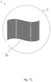
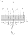
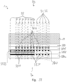
- the Figure 1 shows a security element 1 with a front side 3b and a rear side 3a opposite the front side 3b in cross section, wherein the security element 1 has two or more security features 2, wherein a first security feature 2a of the two or more security features 2 comprises one or more first layers 21 and a second security feature 2b of the two or more security features 2 comprises one or more second layers 22, wherein the first security feature 2a and the second security feature 2b are arranged in particular in register with one another, wherein the first security feature 2a generates at least one first optically variable effect and the second security feature 2b generates at least one second optically variable effect, wherein the at least one first optically variable effect has a first color and the at least one second optically variable effect has a second color, wherein the first color and the second color differ from one another.
- the security element 1 comprises a carrier layer 10.
- a first layer 21 is applied in three first regions 31, this first layer 21 being designed as a first color layer 213.
- a further first layer 21 is applied, which is designed as a first replication layer 216.
- a further first layer 21 is applied in the three first regions 31, which is designed as a first metal layer 217.
- the functional layer 20, the first color layer 213, the first replication layer 216 and the first metal layer 217 preferably form the first security feature 2a. Such a security feature 2a is also described in the Figure 2 shown.
- the security feature 1 shown further comprises, on the side of the first replication layer 216 and the first metal layer 217 facing away from the carrier layer 10, a second layer 22 in a second region 32, which is designed as a second color layer 223.
- a second replication layer 226 is applied on the side of the first replication layer 216 and the second color layer 223 facing away from the carrier layer 10.
- the side of the second replication layer 226 has a further second layer 22, which is formed as a second metal layer 227 in the second region 32.
- the second color layer 223, the second replication layer 226 and the second metal layer 227 preferably form the second security feature 2b.
- the first color layer 213 and/or one or more layers which form and/or have one or more first optically variable structures are applied to the carrier layer 10 as the first layer 21 or first layers 21.
- the one or more first optically variable structures are formed in the one or more first regions 31 and optically cancelled out in the one or more second regions 32 by a lacquer layer with a refractive index which differs from the underlying layer with the optically variable structures by no more than 0.3, preferably by no more than 0.1. It is possible that in step a, the first color layer 213 is applied to the three first regions 31, but is not applied to the second region 32 or is removed again after application in the second region 32, which does not overlap with the three first regions 31.
- step a the first replication layer 216 is applied as the first layer 21, in particular over the entire surface or in regions, and that in step a a relief structure is molded into the first replication layer 216 as the first optically variable structure.
- step a at least one first opaque layer, in particular a first opaque metal layer, is applied to the first replication layer 216 as the first layer 21, wherein the first opaque layer is preferably applied in the one or more first regions 31, but is not applied in the one or more second regions 32 or is removed there again after application, preferably using the first color layer 213 as an exposure mask in precise registration with the first color layer 213.
- the first metal layer 217 can be formed, for example, as a first opaque metal layer.
- the second color layer 223 and/or one or more layers which form and/or have one or more second optically variable structures are applied as the second layer 22 or second layers 22. It is particularly possible that in step b the second color layer 223 is applied in the second region 32 and in the three first regions 31. It is also possible that in step b the second color layer 223 is applied in the second region 32 and is not applied in the three first regions 31.
- the second replication layer 226 is applied over the entire surface as one of the second layers 22.
- a relief structure is molded onto and/or into the second replication layer 226 as a second optically variable structure. It is possible for the second optically variable structure to be molded both in the three first regions 31 and in the second region 32.
- step b at least one second opaque layer 220a, in particular a second opaque metal layer 220b, is applied to the second replication layer 226 as the second layer 22, wherein the second opaque layer 220a is preferably applied in the second region 32, but preferably is not applied in the three first regions 31 or is removed there again after application.
- the second metal layer 227 can be formed, for example, as a second opaque metal layer.
- the one or more first layers 21, which form the first optically variable structure, and/or the one or more second layers 22, which form the second optically variable structure comprise at least one reflection layer, wherein the at least one reflection layer is formed as an opaque, translucent or transparent reflection layer and is preferably selected from: a metal layer, a partially formed metal layer, a layer of metallic grid points, an HRI layer, an LRI layer or a combination of several HRI layers and/or LRI layers.
- steps a and/or b the first color layer 213 and/or the second color layer 223 and/or the at least one reflection layer are arranged in register with each other.
- one or more second layers of the one or more second layers 22 are applied in step b as one or more opaque, translucent or transparent layers, in particular selected from: metal layer, partially formed metal layer, reflection layer, layer of metallic raster elements, such as raster points and/or raster lines, HRI layer, an LRI layer or a combination of HRI layers and/or LRI layers in the three first regions 31 and/or in the second region 32 on the at least one first replication layer 216 and/or the first metal layer 217 and/or the second replication layer 226.
- opaque, translucent or transparent layers in particular selected from: metal layer, partially formed metal layer, reflection layer, layer of metallic raster elements, such as raster points and/or raster lines, HRI layer, an LRI layer or a combination of HRI layers and/or LRI layers in the three first regions 31 and/or in the second region 32 on the at least one first replication layer 216 and/or the first metal layer 217 and/or the second replication layer 226.
- a positive photoresist and/or a negative photoresist is used, wherein the first color layer 213 and/or the second color layer 223 are used as first etching masks and/or second etching masks. If, for example, a positive photoresist is applied to the first, full-surface applied metal layer 217a and the security element 1 is then exposed to suitable radiation from the front side 3b, i.e. through the carrier layer 10, the positive photoresist is protected from the radiation in the first regions 31 by the first color layer 213.
- the positive photoresist becomes soluble for a subsequently applied suitable solvent, whereby the photoresist is washed away in the regions not protected by the first color layer 213.
- the exposed first metal layer is preferably soluble in the same solution as the photoresist. In this case, the structuring of the first metal layer takes place together with the washing off of the exposed positive photoresist.
- first replication layer 216 and/or the at least one first metal layer 217 and/or the first color layer 213 and/or the second replication layer 226 and/or the second metal layer 227 and/or the second color layer 223 have radiation-curable components which, after application and/or embossing and/or printing onto the carrier layer 10 and/or the first replication layer 216 and/or the first metal layer 217 and/or the first color layer 213 and/or the second replication layer 226 and/or the second metal layer 227 and/or the second color layer 226, are preferably cured by electromagnetic radiation.
- the first color layer 213 is provided as a first exposure mask and/or the second color layer 223 is provided as a second exposure mask during the curing of the first replication layer 216 and/or the first color layer 213 and/or the second replication layer 226 and/or the second color layer 223 by the electromagnetic radiation.
- step a and/or b one or more first openings and/or one or more second openings are made in the first replication layer 216 and/or the first metal layer 217 and/or the first color layer 213 and/or the second replication layer 226 and/or the second Metal layer 227 and/or the second color layer 223 are introduced, wherein the one or more first openings preferably have a transmittance of greater than 50%, in particular greater than 90%, and/or preferably less than 10%, in particular less than 5%.
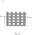
- one or more first layers 20, 213, 216, 217 of the one or more first layers 21 and/or one or more second layers 223, 226, 227 of the one or more second layers 22 are arranged one below the other in several planes. Such a plane is preferably spanned by one of the first and/or second layers 21, 22.
- the security element 1 shown has a spatial arrangement of the first layers 20, 213, 216, 217 and the second layers 223, 226, 227 such that the one or more first layers 20, 213, 216, 217 are arranged above the one or more second layers 223, 226, 227 when the security element 1 is viewed from the front side 3b, and the one or more second layers 22 completely overlap the one or more first layers 21 when the security element 1 is viewed from the back side 3a.
- the second color layer 223 and the second replication layer 226 are applied, into which a second optically variable structure is preferably introduced.
- the introduction of the second optically variable structure is carried out, for example, by thermal replication or by UV replication. It It is possible that the second optically variable structure is vapor-deposited with a second layer consisting of aluminum.
- a third or fourth color layer to be applied to the second replication layer 226 and/or to the second optically variable structure, wherein the first color layer 213 and/or the second color layer 223 are preferably used as a mask, in particular as a first exposure mask and/or as a second exposure mask.
- the carrier layer 10 is in particular transparent or at least translucent.
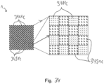
- first security feature 2a is visible in one or more first regions 31 of the security element 1 and the second security feature 2b is visible in one or more second regions 32 of the security element 1 when viewed in incident light from the front side 3b and/or the back side 3a.
- the one or more first regions 31 and/or the one or more second regions 32 adjoin one another at least in sections, in particular physically adjoin one another and/or preferably only appear to adjoin one another for a viewer from the front and/or back.
- the first security feature 2a is opaque in the one or more first regions 31 and transparent or translucent in the one or more second regions 32. It is possible for one or more of the first layers 21 to be formed as an opaque layer, in particular as an opaque metal layer, wherein the opaque layer is provided in the one or more first regions 31, but is not provided in the one or more second regions 32.
- one or more first layers of the one or more first layers 21 form and/or have a first optically variable structure and that one or more second layers of the one or more second layers 22 form and/or have a second optically variable structure.
- the first optically variable structure is in the one or more several first areas 31, but not provided in the one or more second areas 32.
- the first optically variable structure is designed as an optically variable relief structure which is molded into a replication layer, and that in the one or more second regions 32 the optically variable relief structure is optically erased by applying a lacquer layer with a refractive index which differs from the refractive index of the replication layer by no more than 0.3, in particular no more than 0.1.
- the lacquer layer which preferably optically erases the optically variable relief structure, is formed by a second layer of the one or more second layers 22.
- the second optically variable structure 221 is preferably provided both in the one or more first regions 31 and in the one or more second regions 32.
- the one or more first layers 21, which form the first optically variable structure, and/or the one or more second layers 22, which form the second optically variable structure 22 comprise at least one reflection layer 212, wherein the reflection layer 212 is preferably provided in the one or more first regions 31, but is not provided in the one or more second regions 32.
- the reflection layer 212 is formed as an opaque, translucent or transparent reflection layer and is in particular selected from: a metal layer, a partially formed metal layer, a layer of metallic raster elements, in particular raster points, an HRI layer, an LRI layer, a combination of two or more HRI layers and/or LRI layers, in particular layer sequences comprising two or more HIR layers and/or LRI layers.
- the first optically variable structure and/or the second optically variable structure 221 generates an achromatic optically variable effect.
- the first optically variable structure and/or the second optically variable structure 221 comprises an optically effective relief structure, in particular selected from: diffraction grating, hologram, computer-generated hologram, asymmetrical diffraction structure, matt structure, in particular anisotropic matt structure, blaze grating, zero-order diffraction structure, Fresnel-like free-form surface, refractive structure, in particular micromirror arrangement, light-refracting or focusing structure, in particular microlens arrangement.
- an optically effective relief structure in particular selected from: diffraction grating, hologram, computer-generated hologram, asymmetrical diffraction structure, matt structure, in particular anisotropic matt structure, blaze grating, zero-order diffraction structure, Fresnel-like free-form surface, refractive structure, in particular micromirror arrangement, light-refracting or focusing structure, in particular microlens arrangement.
- the first optically variable structure differs from the second optically variable structure 221, in particular that the first optically variable structure differs from the second optically variable structure 221 in one or more structural parameters, in particular in alignment, grating period, grating depth, stochastic parameters, in particular roughness depth, preferably correlation length in matt structures, and/or are assigned to different classes of optically variable structures.
- the at least one first layer of the one or more first layers 21 is preferably designed as a first color layer 213 and/or the at least one second layer of the one or more second layers 22 is preferably designed as a second color layer 223.
- the lacquer layer is formed by the second color layer 223 or a replication layer of the second optically variable structure 221.
- first color layer 213 is provided in the one or more first regions 31, but is not provided in the one or more second regions 32. It is further possible that the second color layer 223 is provided in both the one or more first regions 31 and the one or more second regions 32. It is also possible that the second color layer 223 is provided in the one or more second regions 32 and is not provided in the one or more first regions 31.
- the first color layer 213 and the second color layer 223 have different colors.
- the first color layer 213 and the second color layer 223 are formed as a transparent or translucent layer.
- the first color layer 213 and/or the second color layer 223 is selected from: layer containing dyes and/or pigments, in particular optically variable pigments, liquid crystal pigments, interference layer pigments, interference layer system, in particular consisting of two or more layers with different refractive indices or an absorption layer, a spacer layer and a reflection layer, layer consisting of a liquid crystal material, in particular cholesteric liquid crystal material, volume hologram layer, metal layer.
- layer containing dyes and/or pigments in particular optically variable pigments, liquid crystal pigments, interference layer pigments, interference layer system, in particular consisting of two or more layers with different refractive indices or an absorption layer, a spacer layer and a reflection layer
- layer consisting of a liquid crystal material in particular cholesteric liquid crystal material, volume hologram layer, metal layer.
- first color layer 213 and/or the second color layer 223 and/or the reflection layer are arranged in register with each other.
- At least a first layer of the one or more first layers 21 is formed by a replication layer, preferably formed over the entire surface, that an optically active relief structure is molded into at least one surface of the replication layer and is covered in the one or more first regions 31 with one of the one or more first layers 21, which are designed as an opaque metallic reflection layer, but the surface of the replication layer is not covered with the opaque metallic reflection layer in the one or more second regions 32.
- At least a second layer of the one or more second layers 31b is formed by a replication layer, preferably formed over the entire surface, that an optically active relief structure is molded into at least one surface of the replication layer and is covered in the one or more second regions 32 with one of the one or more second layers 22, which are designed as a reflection layer.
- At least one first layer of the one or more first layers 21, preferably in the one or more first regions 31, has one or more first openings and/or that at least one second layer of the one or more second layers 22, preferably in the one or more second regions 32, has one or more second openings, wherein the first openings and/or the second openings in particular have a transmittance of greater than 50%, preferably greater than 90%, and wherein the at least one first layer of the one or more first layers 21 outside the first openings in particular have a transmittance of less than 10%, preferably less than 5%.
- the one or more first openings and/or the one or more second openings are provided as first grids and/or as second grids, wherein the distances between the first grids and/or the second grids, in particular the average distances between the first grids and/or the second grids, are preferably less than or equal to 300 ⁇ m, in particular less than or equal to 150 ⁇ m.
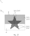
- At least a first region of the one or more first regions 31 and at least a second region of the one or more second regions 32 having a second grid to overlap in such a way that the at least one first optically variable effect and the at least one second optically variable effect can be detected by a viewer from the front side 3b or the back side 3a, in particular in incident light and/or in transmitted light.
- the at least one first optically variable effect and/or the at least one second optically variable effect when tilting and/or bending and/or rotating the security element 1 provides a sequence of colors, in particular a sequence of color values and/or a sequence of color brightnesses and/or a sequence of color saturations, and/or a color change, in particular a color value change and/or a color brightness change and/or a color saturation change, which generate a movement effect, a morphing effect and/or a flip effect, in particular a color flip effect, and/or a virtually protruding or receding 3D shape.
- the Figure 1 shows that the second color layer 223 as the second exposure mask completely overlaps and projects beyond the first color layer 213 as the first exposure mask.
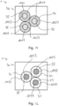
- the three first regions 31 and/or the second region 32 are each formed in the form of a design element 4, in particular as: an alphanumeric character, a code, in particular a barcode, a character, a symbol, a micro-font, an image, a logo, a coat of arms or a motif.
- a design element 4 in particular as: an alphanumeric character, a code, in particular a barcode, a character, a symbol, a micro-font, an image, a logo, a coat of arms or a motif.
- the first color layer 213 and/or the second color layer 223, which in particular have a homogeneous coloring one or more different colors are preferably arranged next to one another or at least partially overlapping, for example as a motif and/or image.
- first color layer 213 and/or the second color layer 223 may have a color gradient and/or a color gradient in at least one predetermined direction.
- the one or more colors, preferably the first color and/or the second color, of the first color layer 213 and/or the second color layer 223 change gradually, in particular with regard to the color saturation, and/or have a gradient in the color tone.
- first color layer 213 and/or the second color layer 223 or at least one further color layer to be formed as an opaque to semi-opaque color layer.
- the register preferably perfect register, between the first color layer 213 and/or the second color layer 223 and the first metal layer 217 and/or the second metal layer 227 can preferably be produced by means of a washing process in which in particular a color layer 213, 223 created in a first step serves as a mask in order to preferably wash off a metal layer 217, 227 located underneath in the register.
- a coating with a single-layer or multi-layer adhesive layer is then applied, with optional additional layers preferably serving as adhesion promoter layers and/or barrier layers and/or stabilization layers and/or leveling layers, so that the security feature, in particular the first security feature and/or the second security feature, is transferred to a substrate to be secured and/or a security document, for example by means of hot embossing. It is also possible for the coating to be carried out with an adhesion promoter layer which is designed in particular for subsequent transfer by means of cold embossing. Furthermore, depending on the application and substrate material, it is possible to dispense with an adhesive layer.
- the Figure 2 shows in particular a film comprising a first security feature 2a in cross section, wherein the security feature 2a is preferably formed by the functional layer 20, the first color layer 213, the first replication layer 216 and the first metal layer 217.
- One or more first layers 21 are applied to a carrier layer 10, which preferably consists of PET and has a thickness of 4.5 ⁇ m to 100 ⁇ m, preferably 12 ⁇ m-50 ⁇ m.
- a of the first layers 21 is formed as a first color layer 213, wherein the first color layer 213 is applied in three first regions 31 on the side facing away from the carrier layer 10 of a further first layer 21, which is formed as a functional layer 20.
- a first replication layer 216 is applied on the side of the functional layer 20 and the first color layer 213 facing away from the carrier layer 10. Furthermore, a first metal layer 217 is applied in the three first regions 31 on the side of the first replication layer 216 facing away from the carrier layer 10.
- the first color layer 213 is used as a mask or mask layer for register-accurate or register-accurate structuring of the first metal layer 217, which is applied in particular to the first replication layer 216, wherein the first replication layer 216 preferably has first optically variable structures.
- the first color layer 213 may be applied, for example, by means of a printing process or for a colored photosensitive layer to be exposed by means of a photolithographic process, the photosensitive layer then being structured according to the exposure and/or the intensity distribution of the exposure.
- the colored photosensitive layer structured in this way preferably functions or is, preferably subsequently, as or the first color layer 213.
- the Figure 3 shows a security element 1 not claimed, comprising a carrier layer 10, wherein a first layer 21 is applied to the back side 3a of the carrier layer 10, which is designed, for example, as a functional layer 30.
- a first layer 21 is applied in three first areas 31, wherein this first layer 21 is designed as a first color layer 313.
- a further first layer 21 is applied, which is designed as a first replication layer 316.
- first replication layer 316 On the side of the first replication layer 316 facing away from the carrier layer 10, a further first layer 21 is applied in the three first areas 31, which is designed as a first metal layer 317.
- the functional layer 30, the first color layer 313, the first replication layer 316 and the first metal layer 317 preferably form a first security feature.
- the security element 1 shown further has a second layer 22 on the side of the first replication layer 316 and the first metal layer 317 facing away from the carrier layer 10, which is designed as a second color layer 323 in two second regions 32.
- a second replication layer 326 is applied to the side of the first replication layer 316 and the second color layer 323 facing away from the carrier layer 10.
- the side of the second replication layer 326 facing away from the carrier layer 10 has a further second layer in the three second regions 32, which is designed as a second metal layer 327.
- the second color layer 323, the second replication layer 326 and the second metal layer 327 preferably form the second security feature.
- One of the first regions 31 completely overlaps with one of the second regions 32.
- the Figure 3 further shows that the second color layer 323 partially overlaps with the first color layer 313. Furthermore, the second color layer 323 has in particular a recess between the left second region 32 and the right second region 32. It is in particular possible that the first color layer 313 in combination with the first metal layer 317 serves as a mask for the second metal layer 327. Preferably, a viewer does not detect the second metal layer 327 when viewing the security element 1 from the front side 3b in the first regions 31 with the first metal layer 317, since the first metal layer 317 is in particular opaque and preferably no optical effect of the second metal layer 327 can be detected.
- the Figure 4a shows a security element 1 not claimed, comprising a carrier layer 10, wherein a functional layer 40 is formed on the back side 3a of the carrier layer 10.
- a first replication layer 416 is formed on the side of the functional layer 40 facing away from the carrier layer 10.
- a first metal layer 417 is formed on the side of the first replication layer 416 facing away from the carrier layer 10 in the three first regions 31.
- the functional layer 40, the first replication layer 416 and the first metal layer 417 preferably form a first security feature.
- the color of the first security feature 2a is essentially determined by the choice of the material of the metal layer 417 and the structures molded into the replication layer 416.
- the color of the first security feature is preferably metallic silver when using essentially achromatic structures and a metal layer made of aluminum or silver.
- the security element 1 shown further has a first color layer 413 in the second region 32 on the side of the first replication layer 416 and the first metal layer 417 facing away from the carrier layer 10.
- the security element 1 further has a second replication layer 426 on the side of the first replication layer 416 and/or the first metal layer 417 and/or the first color layer 413 facing away from the carrier layer 10.
- the side of the second replication layer 426 facing away from the carrier layer 10 has a second metal layer 427 in the second region 32.
- the first color layer 413, the second replication layer 426 and the second metal layer 427 form the second security feature 2b.
- the security element 1 shown corresponds in particular to the Figure 1 shown security element, except for the difference that there is no first color layer.
- the security element 1 when the security element 1 is viewed in incident light from the front side 3b, the light reflected by the first metal layer 417 is in particular not filtered by a first color layer.
- the color of the metallic reflection on the first metal layer 417 can be detected, which can be detected as silver when aluminum is used or copper-colored when copper is used as the reflection layer.
- methods such as etching methods, washing methods, mask exposure, or also the so-called zero.zero demetallization method can be used for the first metal layer, wherein these methods preferably enable a high resolution and/or registration accuracy for the first optically variable effect.
- Figures 4b to 4d show the structure of the security element 1 and the interaction of a first security feature 2a and a second security feature 2b in schematic plan views.
- the security element 1 is formed as a round patch, the outer edge 5 of which is indicated by a dashed line.
- Figure 4b shows a separate optical effect of the first security feature 2a when viewed vertically.
- the optical effect is preferably composed of diffractive movement effects in or along the metallic line elements shown in black, a virtually three-dimensionally protruding, achromatic, metallized star near the center of the first security feature 2a and the number "55" as an achromatic matte area.
- the virtually three-dimensionally protruding, achromatic, metallized star is realized via a Fresnel free-form surface.
- the first security feature 2a has no color layer and thus appears essentially metallic silver.
- Figure 4c shows a separate optical effect of the second security feature 2b when viewed vertically.
- the optical effect is preferably composed of brightness bands that move horizontally depending on a changing viewing and/or illumination angle and are realized via achromatic, anisotropic matt structures.
- the optical effect can be seen in a flag-shaped metallized area with dashed interruptions. Due to the color layer 413 lying in front of the structures and the second metal layer 427 for a viewer looking at the security element 1 from the front side 3b, the horizontally moving brightness bands appear monochromatic in the color of the color layer 413.
- the second security feature 2b has a thin-film structure consisting of at least three layers instead of a colour layer and a metal layer: Absorber layer, in particular comprising an 8 nm thick chromium layer, Transparent spacer layer, in particular comprising at least one layer with a thickness of 450 nm and/or consisting of MgF 2 or in particular comprising a polymeric lacquer layer with a thickness of 500 nm, and Metallic mirror layer, in particular comprising at least one layer with a thickness of 25 nm and/or consisting of aluminum.
- Absorber layer in particular comprising an 8 nm thick chromium layer
- Transparent spacer layer in particular comprising at least one layer with a thickness of 450 nm and/or consisting of MgF 2 or in particular comprising a polymeric lacquer layer with a thickness of 500 nm
- Metallic mirror layer in particular comprising at least one layer with a thickness of 25 nm and/or consisting of aluminum.
- the horizontally moving brightness bands preferably appear in different colors, especially depending on the viewing angle.
- the brightness bands can appear in reddish tones when viewed normally at about 25° and in greenish tones when tilted to about 40°.
- Figure 4d shows the combined optical effect of the first security feature 2a, in particular shown in the Figure 4b , and the second security feature 2b, in particular shown in the Figure 4c , when viewed vertically.
- the perfect register of the silver metallic star in the center of the security element 1 to the background appearing in the color of the color layer 413 is easily comprehensible and easily communicated to a viewer.
- the second security feature 2b also has a computer-generated hologram in addition to the achromatic, anisotropic matt structures.
- This computer-generated hologram is preferably only provided in the area of the second security feature 2b, which is located behind the virtually three-dimensionally protruding, achromatic, metallized star near the center of the first security feature 2a.
- this star is not metallized over its entire surface, but has a demetallized line or dot grid, preferably with a surface area of 10% to 20% of demetallized lines and/or dots.
- the line grid and/or dot grid preferably has a periodicity which is below the resolution limit of the human eye.
- This periodicity is preferably less than or equal to 300 ⁇ m and more preferably less than or equal to 150 ⁇ m.
- the computer-generated hologram is calculated in particular in such a way that when illuminated with a point light source, it displays an icon, a motif and/or symbols, such as numbers, letters and/or denomination symbols, and/or an image, such as a barcode, clearly and sharply.
- the icons and/or symbols and/or images to be displayed appear very blurred and are therefore barely perceptible to the human eye.
- such a security element 1 appears to an observer when illuminated with non-directional light sources preferably almost like the one in Figure 4d shown security element 1.
- a point light source such as the spotlight of a smartphone
- the icon and/or the symbol and/or the image of the computer-generated hologram appears to float in particular above the star, wherein the icon and/or the symbol and/or the image appears in the color of the color layer 413, while the star is preferably perceived as metallic silver.
- Figure 4e shows the combined optical effects of a first security feature 2a and a second security feature 2b when viewed vertically and illuminated with a point light source, wherein the computer-generated hologram in this example represents the letter "K" and preferably overlaps with a virtually three-dimensionally protruding, achromatic, metallized star near the center of the first security feature 2a.
- the security element 1 in particular a security element according to the invention, to comprise a first security feature 2a consisting of a high-resolution partial metallization 417a, preferably made of aluminum.
- a first security feature 2a preferably has an achromatic radial movement effect as an optically variable effect.
- the partial metallization 417a is in particular selected so that the grayscale image of a violet is displayed.
- the grayscale image of metallic and/or metallized pixels 418f preferably has a resolution of at least 250 dpi, more preferably of at least 500 dpi, even more preferably of 1000 dpi and particularly preferably of at least 1500 dpi.
- a second security feature is preferably visible to the viewer behind the first security feature 2a and consists in particular of a colored layer of color, for example blue, and a partial metallization preferably behind the colored layer, in particular the partial metallization 417a, preferably made of aluminum, in particular for the viewer in front of or behind the color layer, for example made of aluminum.
- the partial metallization 417a of the security feature 2a in particular comprising a metallic and/or metallized region 418f, preferably has the shape of the violet blossom, as in Fig. 4g shown schematically.
- the optically variable effect of the second security feature can, for example, be an endless pattern made up of high-frequency linear gratings with a grating period of approximately 300 nm to 350 nm and/or can be generated by high-frequency linear gratings with a grating period of approximately 300 nm to 350 nm.
- a blue violet preferably appears, with the color gradient, for example from light blue to darker blue, being generated by the high-resolution partial metallization 417a over the blue color layer.
- the radial pumping effect can be seen in particular in the violet. If the security feature is tilted strongly over the horizontal axis, the endless pattern, in particular a large number of small bees, preferably appears in the non-metallized and/or non-metallic areas 418f, for example the aluminum layer, in diffractive colors, which are preferably modified by the filter effect of the blue color layer.
- the Figure 5 shows a security element 1, in particular in a first process stage, comprising a carrier layer 10, a functional layer 50 formed on the back side 3a of the carrier layer 10, and a first replication layer 516 formed on the side of the functional layer 50 facing away from the carrier layer 10.
- the Figure 5 five first regions 31 in which a first metal layer 517 is formed on the side of the first replication layer 516 facing away from the carrier layer 10.
- the first process stage is preferably understood to mean the formation of the first metal layer 517 as the first partial metallization.
- the Figure 6 shows this in the Figure 5 shown security element 1, except that the security element 1 is preferably in a second process stage.
- a first color layer 613 is applied in a second region 32 to the side of the first replication layer 616 and the first metal layer 617 facing away from the carrier layer 10, for example printed by means of gravure printing.
- the Figure 7 shows this in the Figure 6 shown security element 1, except that the security element 1 is preferably in a third process stage.
- the first color layer 713 is used in the third process stage as an etching resist to trim the first metal layer 717 such that the formation of the first metal layer 717 is preferably limited to the first regions 31 and the second region 32.
- the first color layer and/or the second color layer has the function of an etching resist, wherein in particular the partial metallization produced in a first step or the first metal layer 717 and/or a second metal layer is trimmed in an additional etching step to the region of the color layer or the first color layer 713 and/or a second color layer.
- the Figure 8 shows a non-claimed security element 1, which preferably has the same layer structure as the one in the Figure 7 shown security feature, except that security feature 1 has a first color layer 813, a second color layer 823 and a second metal layer 827 in a second region 32 and has a first metal layer 817 in four first regions 31.
- the first color layer 813 and/or the second color layer 823 determines the external shape of the partial metallization or the first metal layer 817 and/or the second metal layer 827, which are preferably limited at least by the external boundaries of the second region 32. It is possible to form the fine structure of the partial metallization within the second region 32, which comprises the first color layer 813, by means of an additional method. For example, it is possible to use photolithographic methods or Printing processes, etching resist processes, blocking fund processes, washing processes and/or lift-off processes and/or alkali printing processes.
- the second color layer 823 preferably has the second color.
- the Figure 9 shows a non-claimed security element 1 comprising a carrier layer 10, on the back side 3a of which a functional layer 90 is applied.
- the side of the functional layer 90 facing away from the carrier layer 10 has a first color layer 913 in three first regions.
- the side of the functional layer 90 and the first color layer 913 facing away from the carrier layer 10 has a first replication layer 916.
- a first metal layer 917 is applied in the three first regions 31 and a second color layer 923 is applied in the two second regions 32.
- the side of the first metal layer 917 facing away from the carrier layer 10 has a third color layer 933 in the three first regions 31.
- the first metal layer 917 is arranged in precise registration with the first color layer 913 and the third color layer 933.
- the first color layer 913 is printed in the decoration, i.e. in particular partially, in a first step.
- the first replication layer 916 is preferably applied and preferably provided with an optically variable structure in a third step.
- the first metal layer 917 is applied over the entire surface of the first replication layer 916 in a fourth step.
- the first color layer 913 is used in particular as a mask with a positive photoresist for the region-by-region structuring of the first metal layer 917.
- the metal layer 917 is preferably only present in the regions 31.
- the second color layer 923 in a sixth step in the form of a colored negative photoresist, in particular by using the first metal layer 917 as a mask.
- the third color layer 933 is preferably applied as a colored positive photoresist and the first metal layer 917 is again used as a mask in order to preferably Figure 9 to obtain security element 1 shown.
- the Figure 10 shows this in the Figure 9 shown security element 1, except that the side of the first replication layer 1016, the second color layer 1023 and the third color layer 1033 facing away from the carrier layer 10 has a second replication layer 1026 over its entire surface and a metal layer 1027 partially in the second regions 32.
- a fourth color layer 1043 is applied in the second regions 32 to the side of the second metal layer 1027 facing away from the carrier layer 10.
- the second metal layer 1027 in register accuracy using the first metal layer 1017 as a mask, in particular to structure it in regions, for example by means of a colored negative resist, which remains in particular as the fourth color layer 1043 in the layer structure of the security element 1.
- two different optically variable effects are register-accurate with two identical or different colors of the first and second color layers 1013, 1023 as combined optical impressions for a viewer from the front side 3b of the security element 1, as shown in the Figure 11 shown, and two identical or different colours of the third and fourth colour layers 1033, 1043 or the above colours can be detected in register with the optically variable effects from the back 3a of the security element 1, as shown in the Figure 12 shown.
- such a security element 1 is particularly advantageous for window areas.
- the Figure 13 shows a non-claimed security element 1 comprising a carrier layer 10 and further layers which are formed in the sequence: functional layer 130, first replication layer 1316, first color layer 1313 in second regions 32, first metal layer 1317 in first regions 31 and the second regions 32, negative photoresist 1318, on the back side 3a of the carrier layer 10.
- the first color layer 1313 is applied after the first replication layer 1316, so that the replication is eliminated, in particular in areas in which the first color layer 1313 overlaps the first replication layer 1316.
- photolithographic structuring in particular region-wise structuring, preferably either an external mask is used and/or the first color layer 1313 is used as a mask and/or special structures in the replication are used as a mask.
- the first color layer 1313 is used as a mask, wherein, in particular after the removal of the negative photoresist 1318 and the unprotected first metal layer 1317, a first metal layer 1317 is produced in the first regions 31 as a partial metallization with colored, transparent recesses, as in Figure 14
- the Figure 17 shows a non-claimed security element 1 comprising a carrier layer 10 and further layers which are formed in the sequence: functional layer 170, first replication layer 1716, first color layer 1713 in second regions, first metal layer 1717 in first regions, second replication lacquer layer 1726, second metal layer 1727, on the back side 3a of the carrier layer 10.
- first color layer 1713 is applied and/or introduced into the areas of the second optically variable structures 1721 of the second replication layer 1726 in order to preferably cancel out the optical effect of the first optically variable structures there.
- second optically variable structures 1721 are in particular introduced into the second replication layer 1726 in such a way that it preferably at least partially overlies and/or overlaps the first color layer 1713.
- the Figure 18 shows this in the Figure 17 shown security element 1, except that the first color layer 1813 is applied in particular in the areas of the first replication layer 1816, which preferably do not have any first optically variable structures 1811. It is possible for the first color layer 1813 to overlap with the first optically variable structures in edge areas.
- the second replication layer 1826 has second optically variable structures 1821 such that they in particular at least partially overlap with the first color layer 1813.
- the Figure 19 shows a security element 1 in plan view from the front side 3b, wherein in first areas 31 in particular the first color layer 1813 for a viewer and in second areas 32 in particular the first metal layer 1817 is detectable for a viewer.
- the Figure 20 shows a security element 1 in plan view from the back 3a, wherein in first areas 31 in particular the second metal layer 1827 is detectable by an observer.
- the Figure 21 shows a non-claimed security element 1 comprising a carrier layer 10 and further layers, which are formed in the sequence: functional layer 210, first replication layer 2116, first metal layer 2117 in a second region 32, first color layer 2113 in the second region 32, second replication lacquer layer 2126, second metal layer 2127 in first regions 31, second color layer 2123 in first regions 31, on the back side 3a of the carrier layer 10.
- the first optically variable effect and/or the second optically variable effect when viewing the security element 1 in a structure according to Figure 21 detectable by a viewer from the back 3a.
- a security element for example, in PCI products (KINEGRAMO inside a polycarbonate card), in which the security element is applied in particular to a polycarbonate film, wherein the polycarbonate film with the security element is preferably embedded in such a way that the back 3a of the security element 1 is detectable by a viewer from the outside.
- first metal layer 2117 and/or the second metal layer 2127 with a colored etching resist, in particular to structure it in certain areas.
- Photostructurable, colorable lacquers such as negative resists or positive resists, are particularly suitable for high resolutions.
- the first color layer 2113 and/or the second color layer 2123 has the function of an etching resist, wherein in particular the partial metallization produced in a first step or the first metal layer 2117 and/or the second metal layer 2127 are applied in an additional etching step to the region of the color layer or the first color layer 2113 and/or the second color layer 2123.
- the Figure 22 shows this in the Figure 1 shown security element 1, except that the second metal layer 2227 is arranged in three different regions, wherein these regions at least partially overlap with the second region 32 and the first regions 31.
- the second metal layer 2227 is structured as a second partial metallization, wherein, when viewed perpendicular to the plane spanned by the carrier layer 10, preferably areas without a metal layer and with a color layer are detectable.
- the layer structure is preferably partially transparent, wherein the substrate is detectable for a viewer in particular from the front side 3b or from the back side 3a through the first and/or second security feature.
- the carrier layer 10 When viewed from the front, the carrier layer 10 preferably appears colored in the area of the first and/or second security feature due to the optical effect of the second color layer 2223. The same preferably applies to a substrate or to a document to which the security feature is applied.
- the Figure 23 shows this in the Figure 22 shown security element 1, except that the second color layer 2323 is formed in second regions 32.
- first color layer 2313 and/or the second color layer 2323 as a mask for the structuring, in particular the region-wise structuring, of the first metal layer 2317 and/or the second metal layer 2327.
- the carrier layer 10 in contrast to the Figure 22 or 9 shown security element 1 is preferably detectable without a color impression, which is generated by the second color layer 2323.
- the carrier layer 10 in contrast to the Figure 22 or 9 shown security element 1 is preferably detectable without a color impression, which is generated by the second color layer 2323. The same applies to the substrate or a document after a transfer.
- the Figure 24 shows a security element 1 in plan view, wherein the security element 1 has a first color layer 2413, which is shaped in the form of a line grid, and preferably a first metal layer is structured in register with this.
- the security element 1 also has a second color layer 2423, which is shaped in the form of a second line grid, and preferably a second metal layer is structured in register with this in areas where the first metal layer is not present.
- the line grids are preferably selected so that the individual lines cannot be resolved by a human eye, wherein the grid spacings are in particular smaller than 300 ⁇ m, preferably smaller than 150 ⁇ m.
- Photolithographic processes are particularly advantageous for fine grids, since they can achieve a significantly higher resolution.
- a first color from a negative photoresist can be structured in high resolution using mask exposure and can serve as a mask for the precise structuring of a further metal layer in further process steps.
- variable b preferably designates the line width of the respective line raster and the variable d preferably designates the period of the Line rasterization. If the period d is significantly below the typical resolution limit of the human eye, the line rasterization is particularly not recognizable with the human eye. It has proven advantageous to select periods d which are in particular smaller than 300 ⁇ m, preferably smaller than 150 ⁇ m. In particular, instead of a line raster, dot rasters and/or other raster forms are used for the raster elements.
- the Figure 25 shows this in the Figures 26 and 27 shown security element 1 in cross section, wherein the first metal layer 2517 together with the first color layer 2513 and the second metal layer 2527 together with the second color layer 2523 are each formed as a line grid. It is possible to use a colored etching resist for the second color layer 2523.
- the Figures 26 and 27 show that in the Figure 25 shown security element 1 in plan view or from the front side 3b, in particular through the carrier layer 10, and from the back side 3a.
- first metal layer 2517 is preferably arranged in register with the first color layer 2513 and the second metal layer 2527 is preferably arranged in register with the second color layer 2523, wherein the metal layers 2517, 2527 appear in particular silver when viewed without a color layer.
- widths of the raster lines and/or the sizes of differently shaped raster elements may vary, for example according to a predetermined function, in order to generate additional optical information, in particular when viewed in transmitted light.
- the mask exposure method or the so-called zero.zero demetallization method is used for a fine structuring, in particular a fine area-wise structuring of the first color layer 2513, preferably a metal layer without a color layer.
- a fine structuring in particular a fine area-wise structuring of the first color layer 2513, preferably a metal layer without a color layer.
- the mask exposure process to structure a color layer, in particular through a photosensitive layer with high resolution, preferably to structure it in areas.
- the Figure 28 shows a security element 1 in a plan view from the front side 3a.
- a first color layer 2813 is deposited in particular with a first metal layer in precise registration and preferably shows a first optically variable effect, for example a change in brightness when the security element 1 is tilted and/or diffraction effects.
- a second color layer 2823 is formed in areas which are not covered by the first color layer 2813.
- the second color layer 2823 is deposited in particular with a second metal layer in precise registration.
- the first optically variable effect is preferably detectable by a viewer in the areas of the lettering "UTO" and "50", which comprise the first color layer 2813 and the first metal layer.
- the Figure 29 shows this in the Figure 28 shown security element 1 comprising a virtual cutting line and the Figure 30 shows a cross-section of this security element at the position or along the virtual cutting line 6, whereby the Figure 30 Security element 1 shown essentially corresponds to the structure of the Figure 1 shown security element.
- the Figure 30 shows a non-claimed security element 1 comprising a carrier layer 10 and further layers which are formed in the sequence: functional layer 300, first color layer 3013 in first regions 31, first replication layer 3016, first metal layer 3017 in the first regions 31, second color layer 3023 in the second region 32, second replication layer 3026, second metal layer 3027 in the second region 32 and in the first regions 31, on the back side 3a of the carrier layer 10.
- first replication layer 3016 it is possible for the first replication layer 3016 to be thicker than the first color layer 3013, with the first replication layer 3016 in particular covering the first color layer 3013 and leveling out level differences. It is also possible for the second replication layer 3026 to conceal level differences and preferably level the layer composite of the first metal layer 3017 and the second color layer 3023.
- a second metal layer 3027 is preferably arranged on the second color layer 3023 in register with the first and/or second color layer 3013, 3023 and/or in register with the first metal layer 3017. It is possible for an optional leveling layer 300a to fill the height differences between the second replication layer 3026 and the second metal layer 3027.
- the carrier layer is preferably a transparent plastic film with a thickness between 4.5 ⁇ m and 125 ⁇ m, preferably between 12 ⁇ m and 50 ⁇ m, more preferably between 16 ⁇ m and 23 ⁇ m.
- the carrier layer 10 is in particular monoaxially or biaxially stretched. It is also possible for the carrier layer to consist not only of one layer, but also of several layers.
- the carrier layer it is possible for the carrier layer to have a release layer in addition to a plastic carrier, for example a plastic film described above, which enables the functional layer to be detached from the plastic film down to the leveling or adhesive layer of the existing layer structure, for example when using the multilayer body as a hot or cold stamping film.
- the release layer is partially present in order to preferably form a further security feature, such as in the case of a label film.
- the partial release layer preferably leads to the destruction of the security element when it is detached again from a substrate, such as a document.
- the functional layer preferably comprises a release layer, for example made of hot-melt material, which enables the carrier layer 10 to be detached from the other layers of the multilayer body, which are arranged on a side of the release layer facing away from the carrier layer 10, is particularly facilitated.
- a release layer for example made of hot-melt material
- IMD In-Mold Decoration
- the functional layer has at least one protective layer, for example a protective lacquer layer, in addition to a release layer.
- the protective layer preferably forms a protection for layers arranged underneath against abrasion, damage, chemical attacks or the like.
- the top layer after the carrier film has been removed has further functions, such as adhesion in the case of overlamination or ensuring printability, preferably by means of thermal transfer, inkjet and/or offset printing processes.
- the functional layers in particular contain layers which preferably functionally influence the adhesion to or between the adjacent layers.
- a first transparent, colored lacquer layer is printed on the functional layer in individual partial areas.
- Transparent is preferably understood here to mean that the lacquer layer is preferably at least partially permeable to radiation in the visible wavelength range.
- Colored is preferably understood here to mean that the lacquer layer shows a visible color impression in particular in sufficient daylight.
- Both the areas of the functional layer printed with the first lacquer layer and the unprinted areas of the functional layer are preferably covered by a first replication layer, which preferably at least partially levels the relief structure of the decorative layer, i.e. the differing levels in the printed and unprinted areas.
- the replication layer has in particular a relief structure completely or partially.
- a thin metal layer is arranged congruently with the first colored lacquer layer on the first replication layer.
- a second transparent, colored lacquer layer is preferably printed in individual sub-areas on the first metal layer and in the areas of the first replication layer that are not covered by a metal layer. Both the areas printed with the second colored lacquer layer and the unprinted areas, preferably the first replication layer and/or the first metal layer, are in particular covered by a second replication layer, which preferably equalizes the relief structure of the decorative layer, i.e. the differing levels in the printed and unprinted areas. Depending on the lacquer chemistry, application quantity and application conditions, only partial equalization preferably takes place, but this is not crucial for the implementation of the feature.
- the replication layer preferably has a relief structure completely or partially. Preferably, in register and when viewed perpendicular to the plane of the carrier layer, a second thin metal layer is arranged on the second replication layer that is congruent with the first and second lacquer layers and thus in particular also in register with the first metal layer.
- Both the areas of the second replication layer covered with the second metal layer and the uncovered areas of the second replication layer are preferably covered with a leveling layer which equalizes or covers and fills in level differences caused in particular by the relief structure and the metal layer arranged in certain areas, the multilayer body preferably having a largely flat, essentially structureless surface on the side of the leveling layer facing away from the carrier layer.
- the thickness of the leveling layer varies in this way.
- the leveling layer preferably fulfills further functional tasks, such as improving adhesion to subsequent layers, protective functions against chemical and/or physical attacks, as a barrier layer or adhesive layer.
- the compensation layer has a similar refractive index to the second replication layer and/or the refractive index difference is less than about 0.3, then in particular the areas of the relief structure of the second replication layer that are not covered with the second metal layer and directly adjacent to the compensation layer are preferably optically erased because, due to the similar refractive index of both layers, there are preferably no longer any optically recognizable layer boundaries between the replication layer and the compensation layer.
- the multilayer body is preferably a section of a transfer film, for example a hot stamping film, which can be arranged on a substrate by means of an adhesive layer.
- the compensating layer is preferably designed as an adhesive layer, for example hot melt adhesive, or an adhesive layer is connected to the side of the compensating layer facing away from the carrier layer.
- the adhesive layer is in particular hot melt adhesive, which melts when exposed to heat and connects the multilayer body to the surface of the substrate.
- an additional carrier layer is preferably provided on the side of the compensating layer facing away from the first carrier layer, or as an alternative to the adhesive layer, a further carrier layer is provided.
- This laminate body which preferably consists of two outer carrier layers and the inner layers of the multilayer body, can be laminated into card composites for further use, for example in polycarbonate (PC).
- PC polycarbonate
- the carrier layers are made of the same material as the layers of the card composite adjacent to the laminate body, for example PC.
- the Figures 31 and 32 show a security element 1 comprising a so-called diffractive watermark, which is based in particular on asymmetric structures.
- blaze gratings with a grating period between 0.5 ⁇ m and 10 ⁇ m are used as asymmetric structures.
- a nearly An identical blaze grid is used in the lettering and the background. Only the orientation of the two grids is rotated by approximately 180° to each other. It is possible that contrast changes when turning the security element 1 in the plane spanned by the security element 1 from 0° (see Figure 31 ) by 180° (see Figure 32 ) can be generated.
- the background 3113 and the lettering 3123 are supplemented in register by a respective color, such as red and green, whereby in particular a further optical effect is created.
- a dark red lettering 3123 can be detected against a light green background 3113, whereby after a rotation of 180° a light red lettering in particular can be detected against a dark green background ( Fig. 32 ).
- the Figure 33 shows this in the Figures 31 and 32 shown security element 1 in cross section, wherein the layer structure of the security element corresponds in particular to the layer structure of the Figure 1
- the security element shown in the Figures 31 and 32 The effect shown is obtained when viewed from the front 3b.
- a first asymmetrical structure is molded in the areas 31 and a structure rotated by approximately 180° in the areas 32.
- the Figure 34 shows a security element or a part of a security element comprising a square field of size 4mm x 4mm, which in particular has the shape of a 2-dimensional grid, the size of a grid element 3411c or 3421c being, for example, 50 ⁇ m x 50 ⁇ m or 100 ⁇ m x 100 ⁇ m and in particular having differently oriented anisotropically scattering matt structures, which for example have an orientation of +45° and -45° relative to one of the edges of the security element 1. It is possible that both structures 3411c, 3421c each have the colors green and red in register.
- the layer structure of the security element 1 corresponds in cross-section in particular to that in the Figure 1 security element shown.
- a viewer of the security element 1 perceives the square field in a first green color when tilting it to one side, wherein the square field appears in particular in red when tilting it to the other side.
- two isotropically scattering matt structures which preferably scatter in a rotationally invariant manner, with different scattering characteristics, in particular due to different roughness depths and/or different correlation lengths, and/or two grating structures with different structure depths and/or profile shapes.
- Another possibility is to use two achromatically white-reflecting computer-generated holograms with different beam angles.
- the color flip preferably takes place in a different angle range, preferably when rotating and/or tilting.
- a single grid field of the two-dimensional grid with 50 ⁇ m x 50 ⁇ m is well below the resolution limit of the human eye, whereby the square fields appear to an observer in particular as homogeneous.
- the area coverage of the two colors preferably varies locally between 0% and 100%.
- the area coverage of the first color can decrease from 80% to 20% from the edge to the center and conversely the area coverage of the second color can increase from 20% to 80%.
- a screen there are a wide variety of options for the design of a screen, as is known from printing technology, for example, in particular as one-dimensional screens, two-dimensional screens, amplitude-modulated, and/or frequency-modulated.
- the screens can also be provided with a substructure, such as They are known, for example, from security printing, in particular as artistic screening and/or line screens with width modulation.
- the first replication preferably has a coating of anisotropically scattering structures, which, when the feature is moved from left to right, creates two bright bars for an observer, which preferably move from the center to the edges.
- the second replication which is in register with the first replication, preferably shows a motion pattern of concentric rings.
- the Figures 35 and 36 show a non-claimed security element 1 in plan view from the front 3b, or in cross section.
- a Fresnel free-form surface in the shape of a three-dimensional star 3513, 3517.
- the star preferably appears in the color blue and appears partially transparent due to the rasterization.
- a yellow-orange color layer 3523 in front of a metal layer 3527, which in particular shows a dynamic movement effect.
- the free-form surface When the security element 1 is tilted, the free-form surface preferably appears 3-dimensionally in blue, that is to say preferably protruding virtually three-dimensionally, and in the background, in particular through the free-form surface, although preferably weakened by the rasterization of the free-form surface, preferably a movement effect in a different color, wherein the yellow-orange color together with the metal layer can be perceived in particular as a golden color tone.
- both effects and both color impressions can preferably be perceived alternately or jump out at him.
- the grids are one-dimensional or two-dimensional.
- the local area coverage is achieved in particular by means of an amplitude or frequency modulation of the point-shaped and/or line-shaped grid elements.
- the minimum dimensions of a grid such as the diameter of a partial area or the width of a grid line, are one-dimensional rasterization, in the range between 1 ⁇ m and 300 ⁇ m, preferably between 5 ⁇ m and 200 ⁇ m.
- the layer structure of the Figure 36 The security element 1 shown essentially corresponds to the layer structure of the Figure 1 shown security element, apart from the fact that the side of the second replication layer 3626 facing away from the carrier layer 10 and the side of the second metal layer 3627 facing away from the carrier layer 10 have a further functional layer 360a.
- This functional layer 360a is preferably formed as an adhesive layer or sequence of adhesive layers, barrier layers and/or adhesion promoter layers.
- the Figures 37 and 38 show that in the Figures 35 and 36 Security element 1 shown, except that the Figures 37 and 38 shown security element 1 has a partial overlap of the first color layer 3713 and the second color layer 3723.
- the free-form surface In areas in which the free-form surface is not backed by the second color layer 3723, it appears in particular partially transparent, whereby after application to a substrate, the substrate can be detected in particular without a color effect
- the substrate is preferably recognizable without a color effect in the partially transparent areas of the free-form surface that are not backed by the second color layer.
- the Figures 39 and 40 show that in the Figures 37 and 38 shown security element 1, except that the Figures 39 and 40
- the security element 1 shown is provided with a first metal layer 3917 in the central region which is completely opaque, wherein the metallic surface coverage gradually decreases in particular in the edge regions.
- the Figure 41 shows a security element 1 which has star-shaped motifs which have a change in their sizes and/or orientations and/or surface coverage.
- the star-shaped motifs 4113, 4117 on the left side of the Figure 41 have a diameter in the range of millimeters and are preferably visible to the human eye without Aids.
- the star-shaped motifs on the right-hand side have in particular a diameter in the range of a few micrometers and in particular are no longer resolved with the unaided human eye.
- the optically variable effect which is present in the star-shaped motifs in precise registration with the first color layer 4113 and is produced by the microstructures molded in the first metal layer 4117, consists in particular of a brightness gradient from left to right, for example in gold, which can be detected when the security element 1 is tilted.
- the background there are further microstructures 4127 which, when the security element 1 is tilted, show in particular a red brightness gradient that moves from top to bottom.
- the larger star-shaped motifs it is preferably clearly detectable that the golden effect is localized in the individual star-shaped motifs, while on the right-hand side the smaller star-shaped motifs preferably appear like a continuous grid.
- first star-shaped motif with a first color layer and a rasterized first metal layer forming in particular a relief with a virtual three-dimensional curvature which is directed towards the viewer, protrudes, in particular protrudes virtually convexly.
- second star-shaped motif to be formed in a background which has the second color, with an apparent curvature which in particular points away from the viewer, recedes, in particular recedes virtually concavely.
- a viewer When tilting the security element, a viewer perceives the optical impression of a three-dimensional star, in which the viewer preferably perceives a reflection from the upper side in the first color and at the same time preferably receives the impression that he can perceive the rear, "inner" side of the star through the upper side, the reflection of which shines in a color that is different from the first color.
Landscapes
- Credit Cards Or The Like (AREA)
- Laminated Bodies (AREA)
- Diffracting Gratings Or Hologram Optical Elements (AREA)
- Holo Graphy (AREA)
- Printing Methods (AREA)
Applications Claiming Priority (2)
| Application Number | Priority Date | Filing Date | Title |
|---|---|---|---|
| DE102018103236.6A DE102018103236A1 (de) | 2018-02-14 | 2018-02-14 | Sicherheitselement und Verfahren zur Herstellung eines Sicherheitselements |
| PCT/EP2019/053627 WO2019158625A2 (de) | 2018-02-14 | 2019-02-14 | Sicherheitselement und verfahren zur herstellung eines sicherheitselements |
Publications (2)
| Publication Number | Publication Date |
|---|---|
| EP3752371A2 EP3752371A2 (de) | 2020-12-23 |
| EP3752371B1 true EP3752371B1 (de) | 2024-10-09 |
Family
ID=65433674
Family Applications (1)
| Application Number | Title | Priority Date | Filing Date |
|---|---|---|---|
| EP19705341.6A Active EP3752371B1 (de) | 2018-02-14 | 2019-02-14 | Sicherheitselement und verfahren zur herstellung eines sicherheitselements |
Country Status (6)
| Country | Link |
|---|---|
| US (1) | US11155112B2 (https=) |
| EP (1) | EP3752371B1 (https=) |
| JP (1) | JP7474699B2 (https=) |
| CA (1) | CA3090206A1 (https=) |
| DE (1) | DE102018103236A1 (https=) |
| WO (1) | WO2019158625A2 (https=) |
Families Citing this family (20)
| Publication number | Priority date | Publication date | Assignee | Title |
|---|---|---|---|---|
| DE102017106721A1 (de) * | 2017-03-29 | 2018-10-04 | Leonhard Kurz Stiftung & Co. Kg | Verfahren zum Herstellen einer Mehrschichtfolie und eine Mehrschichtfolie sowie ein Sicherheitselement und ein Sicherheitsdokument |
| DE102018005447A1 (de) * | 2018-07-09 | 2020-01-09 | Giesecke+Devrient Currency Technology Gmbh | Optisch variables Sicherheitselement mit reflektivem Flächenbereich |
| DE102019003947A1 (de) * | 2019-06-06 | 2020-12-10 | Giesecke+Devrient Currency Technology Gmbh | Verfahren zum Herstellen eines optisch variablen Sicherheitselements |
| AT522774B1 (de) * | 2019-09-11 | 2021-01-15 | Hueck Folien Gmbh | Sicherheitselement für Wertpapiere oder Sicherheitspapiere mit einer Trägerfolie |
| US12393117B2 (en) * | 2020-02-06 | 2025-08-19 | Dai Nippon Printing Co., Ltd. | Marker, method for manufacturing marker, and detection target |
| WO2022018752A1 (en) * | 2020-07-19 | 2022-01-27 | Pravinchandra Patel Shilpan | Dual-color shift security film |
| DE102020125128A1 (de) * | 2020-09-25 | 2022-03-31 | Leonhard Kurz Stiftung & Co. Kg | Mehrschichtkörper und Verfahren zur Herstellung eines Mehrschichtkörpers |
| DE102020005932A1 (de) * | 2020-09-28 | 2022-03-31 | Giesecke+Devrient Currency Technology Gmbh | Optisch variables Sicherheitselement mit reflektivem Flächenbereich |
| DE102020005912A1 (de) | 2020-09-28 | 2022-03-31 | Giesecke+Devrient Currency Technology Gmbh | Verfahren zum Herstellen eines optisch variablen Sicherheitselements |
| US12227022B2 (en) * | 2021-08-16 | 2025-02-18 | Spectra Systems Corporation | Patterned conductive layer for secure instruments |
| JP7518806B2 (ja) * | 2021-09-30 | 2024-07-18 | 大日本印刷株式会社 | ホログラム積層体 |
| CN114527528B (zh) * | 2022-02-09 | 2023-06-13 | 清华大学 | 闪耀光栅的加工方法及基于闪耀光栅的光学可变器件 |
| CN114706152B (zh) * | 2022-03-15 | 2023-06-20 | 清华大学 | 图案化闪耀光栅的加工方法及系统 |
| DE102023103092A1 (de) * | 2023-02-08 | 2024-08-08 | Giesecke+Devrient Currency Technology Gmbh | Optisch variables Sicherheitselement mit Transmissions- und Reflexionsbereich |
| AT527125B1 (de) * | 2023-05-26 | 2024-11-15 | Adapa Digital Gesmbh | Verfahren zur erzeugung eines optisch maschinenlesbaren identifikators auf einer verpackungsfolie |
| JP2025040976A (ja) * | 2023-09-12 | 2025-03-25 | Toppanホールディングス株式会社 | 成形品及び表示装置 |
| CN121843818A (zh) * | 2023-09-12 | 2026-04-10 | 凸版控股株式会社 | 成型品、显示装置、注塑成型方法、注塑成型品以及液晶面板 |
| DE102023125600A1 (de) | 2023-09-21 | 2025-03-27 | Giesecke+Devrient Currency Technology Gmbh | Verfahren zum Herstellen eines Sicherheitselementes mit Reliefstruktur und Sicherheitselement mit Reliefstruktur |
| WO2025183578A1 (en) * | 2024-03-01 | 2025-09-04 | Polska Wytwornia Papierow Wartosciowych S.A. | Security feature and security feature carrier. |
| WO2025262620A1 (en) * | 2024-06-19 | 2025-12-26 | Istituto Poligrafico E Zecca Dello Stato S.P.A. | Holographic security code and product and corresponding verification system |
Citations (1)
| Publication number | Priority date | Publication date | Assignee | Title |
|---|---|---|---|---|
| EP1997643A2 (de) * | 2007-06-01 | 2008-12-03 | OVD Kinegram AG | Sicherheitsdokument und Verfahren zu dessen Herstellung |
Family Cites Families (39)
| Publication number | Priority date | Publication date | Assignee | Title |
|---|---|---|---|---|
| JPH07314925A (ja) * | 1994-05-30 | 1995-12-05 | Dainippon Printing Co Ltd | 画像形成媒体、転写箔及び画像形成物品 |
| GB9612496D0 (en) | 1996-06-14 | 1996-08-14 | De La Rue Thomas & Co Ltd | Security device |
| AUPO384796A0 (en) | 1996-11-26 | 1996-12-19 | Commonwealth Scientific And Industrial Research Organisation | Colour image diffractive device |
| US6761959B1 (en) | 1999-07-08 | 2004-07-13 | Flex Products, Inc. | Diffractive surfaces with color shifting backgrounds |
| JP4629262B2 (ja) | 2001-04-16 | 2011-02-09 | 大日本印刷株式会社 | 不可視個別情報記録材、不可視個別情報貼付け用ラベル、および不可視個別情報転写シート |
| DE10226114A1 (de) * | 2001-12-21 | 2003-07-03 | Giesecke & Devrient Gmbh | Sicherheitselement für Sicherheitspapiere und Wertdokumente |
| DE10232245B4 (de) * | 2002-07-17 | 2008-06-12 | Leonhard Kurz Gmbh & Co. Kg | Optisch variables Element mit variierender Distanzschicht-Dicke |
| DE10254499B4 (de) | 2002-11-22 | 2005-12-22 | Ovd Kinegram Ag | Schichtanordnung mit einer einen linsenartigen Effekt erzeugenden beugungsoptisch wirksamen Struktur |
| DE10333469A1 (de) | 2003-07-22 | 2005-02-10 | Giesecke & Devrient Gmbh | Sicherheitselement |
| US7738175B2 (en) | 2003-11-21 | 2010-06-15 | Visual Physics, Llc | Micro-optic security and image presentation system providing modulated appearance of an in-plane image |
| DE102005006277B4 (de) | 2005-02-10 | 2007-09-20 | Ovd Kinegram Ag | Verfahren zur Herstellung eines Mehrschichtkörpers |
| DE102005061749A1 (de) | 2005-12-21 | 2007-07-05 | Giesecke & Devrient Gmbh | Optisch variables Sicherheitselement und Verfahren zu seiner Herstellung |
| DE102007039996B4 (de) | 2007-02-07 | 2020-09-24 | Leonhard Kurz Stiftung & Co. Kg | Sicherheitselement für ein Sicherheitsdokument und Verfahren zu seiner Herstellung |
| GB0714141D0 (en) | 2007-07-19 | 2007-08-29 | Rue De Int Ltd | security device |
| DE102007034716A1 (de) | 2007-07-23 | 2009-01-29 | Giesecke & Devrient Gmbh | Sicherheitselement |
| DE102008005019B4 (de) | 2008-01-17 | 2010-08-05 | Ovd Kinegram Ag | Folienelement sowie die Verwendung dieses Folienelements |
| DE102008009296A1 (de) | 2008-02-15 | 2009-08-20 | Giesecke & Devrient Gmbh | Sicherheitselement und Verfahren zu seiner Herstellung |
| DE102008017652A1 (de) | 2008-04-04 | 2009-10-08 | Leonhard Kurz Stiftung & Co. Kg | Sicherheitselement sowie Verfahren zur Herstellung eines Sicherheitselements |
| CN101910876A (zh) | 2008-04-18 | 2010-12-08 | 凸版印刷株式会社 | 显示体及带标签物品 |
| DE102008036481A1 (de) | 2008-08-05 | 2010-02-11 | Giesecke & Devrient Gmbh | Verfahren zur Herstellung von Sicherheitselementen mit zueinander gepasserten Motiven |
| JP5564777B2 (ja) | 2008-10-23 | 2014-08-06 | 凸版印刷株式会社 | セキュリティフィルム、転写箔及び印刷物 |
| FR2941649A1 (fr) | 2009-02-03 | 2010-08-06 | Arjowiggins Security | Element de securite comportant deux motifs distincts superposes, document de securite le comportant et procedes associes. |
| FR2948218B1 (fr) | 2009-07-17 | 2011-11-11 | Arjowiggins Security | Element de securite a effet de parallaxe |
| DE102009040975A1 (de) | 2009-09-11 | 2011-03-24 | Ovd Kinegram Ag | Mehrschichtkörper |
| FR2952193B1 (fr) | 2009-10-30 | 2012-04-20 | Arjowiggins Security | Element de securite comportant un adhesif et un substrat portant une structure optique, et procede associe. |
| JP2011115974A (ja) | 2009-12-01 | 2011-06-16 | Toppan Printing Co Ltd | 偽造防止媒体 |
| FR2953965B1 (fr) | 2009-12-14 | 2011-11-25 | Arjowiggins Security | Element de securite comportant une structure optique |
| GB2505724B (en) | 2010-03-24 | 2015-10-14 | Securency Int Pty Ltd | Security document with integrated security device and method of manufacture |
| DE102011100979A1 (de) * | 2011-05-10 | 2012-11-15 | Giesecke & Devrient Gmbh | Sicherheitselement und mit demselben ausgestatteter Datenträger |
| DE102011102999A1 (de) | 2011-05-24 | 2012-11-29 | Leonhard Kurz Stiftung & Co. Kg | Folie und deren Herstellungsverfahren |
| EP2790042B2 (en) | 2011-12-07 | 2020-01-15 | Toppan Printing Co., Ltd. | Display body, transfer foil, and article with display body |
| DE102013002137A1 (de) | 2013-02-07 | 2014-08-07 | Giesecke & Devrient Gmbh | Optisch variables Flächenmuster |
| JP6237759B2 (ja) | 2013-02-21 | 2017-11-29 | 凸版印刷株式会社 | 表示体およびラベル付き物品 |
| GB201400910D0 (en) | 2014-01-20 | 2014-03-05 | Rue De Int Ltd | Security elements and methods of their manufacture |
| EP3220171B1 (en) | 2014-11-10 | 2022-04-27 | Toppan Printing Co., Ltd. | Optical element for forgery prevention |
| DE102014116940A1 (de) | 2014-11-19 | 2016-05-19 | Leonhard Kurz Stiftung & Co. Kg | Mehrschichtkörper und Verfahren zu dessen Herstellung |
| DE102014117877A1 (de) | 2014-12-04 | 2016-06-23 | Leonhard Kurz Stiftung & Co. Kg | Sicherheitselement |
| GB2538491B (en) | 2015-05-11 | 2017-12-06 | De La Rue Int Ltd | Security documents and methods of manufacture thereof |
| JP2017189888A (ja) | 2016-04-12 | 2017-10-19 | 凸版印刷株式会社 | 偽造防止媒体 |
-
2018
- 2018-02-14 DE DE102018103236.6A patent/DE102018103236A1/de active Pending
-
2019
- 2019-02-14 JP JP2020543323A patent/JP7474699B2/ja active Active
- 2019-02-14 WO PCT/EP2019/053627 patent/WO2019158625A2/de not_active Ceased
- 2019-02-14 US US16/968,256 patent/US11155112B2/en active Active
- 2019-02-14 CA CA3090206A patent/CA3090206A1/en active Pending
- 2019-02-14 EP EP19705341.6A patent/EP3752371B1/de active Active
Patent Citations (1)
| Publication number | Priority date | Publication date | Assignee | Title |
|---|---|---|---|---|
| EP1997643A2 (de) * | 2007-06-01 | 2008-12-03 | OVD Kinegram AG | Sicherheitsdokument und Verfahren zu dessen Herstellung |
Also Published As
| Publication number | Publication date |
|---|---|
| JP2021514485A (ja) | 2021-06-10 |
| WO2019158625A2 (de) | 2019-08-22 |
| US11155112B2 (en) | 2021-10-26 |
| JP7474699B2 (ja) | 2024-04-25 |
| US20210031553A1 (en) | 2021-02-04 |
| CA3090206A1 (en) | 2019-08-22 |
| DE102018103236A1 (de) | 2019-08-14 |
| WO2019158625A3 (de) | 2019-11-21 |
| EP3752371A2 (de) | 2020-12-23 |
Similar Documents
| Publication | Publication Date | Title |
|---|---|---|
| EP3752371B1 (de) | Sicherheitselement und verfahren zur herstellung eines sicherheitselements | |
| EP2635444B1 (de) | Sicherheitselement und verfahren zur herstellung eines sicherheitselements | |
| EP2310211B1 (de) | Sicherheitselement sowie verfahren zu seiner herstellung | |
| EP3565722B1 (de) | Wertdokument | |
| EP3013598B2 (de) | Verfahren zur herstellung eines mehrschichtkörpers | |
| EP2708371B1 (de) | Optisch variables Sicherheitselement mit zusätzlichem Auf-/Durchsichtseffekt | |
| EP3245073B1 (de) | Mehrschichtkörper und verfahren zu dessen herstellung | |
| WO2008095698A1 (de) | Sicherheitselement für ein sicherheitsdokument und verfahren zu seiner herstellung | |
| DE102021123069B4 (de) | Funktionselement, ein Verfahren zur Herstellung eines Funktionselements und ein Produkt | |
| EP3034315B1 (de) | Sicherheitselement, verfahren zum herstellen desselben und mit dem sicherheitselement ausgestatteter datenträger | |
| DE102004046695A1 (de) | Optisch variables Sicherheitselement | |
| WO2024002680A1 (de) | Sicherheitsdokument, system zur herstellung eines sicherheitsdokuments und verfahren zur herstellung eines sicherheitsdokuments | |
| EP4536485B1 (de) | Verfahren zur herstellung eines mehrschichtkörpers, mehrschichtkörper, verfahren zur authentifizierung eines mehrschichtkörpers und ein authentifizierungssystem | |
| EP4509327B1 (de) | Funktionselement, ein verfahren zur herstellung eines funktionselements und ein produkt | |
| EP3787906A1 (de) | Sicherheitselement, datenträger und verwendung | |
| EP3221753B1 (de) | Mehrschichtkörper und verfahren zu dessen herstellung | |
| EP3954543B1 (de) | Optisch variables sicherheitselement | |
| EP2138318B2 (de) | Sicherheitselement mit Aussparungen und Verfahren zur Herstellung desselben | |
| EP4711147A1 (de) | Sicherheitselement |
Legal Events
| Date | Code | Title | Description |
|---|---|---|---|
| STAA | Information on the status of an ep patent application or granted ep patent |
Free format text: STATUS: UNKNOWN |
|
| STAA | Information on the status of an ep patent application or granted ep patent |
Free format text: STATUS: THE INTERNATIONAL PUBLICATION HAS BEEN MADE |
|
| PUAI | Public reference made under article 153(3) epc to a published international application that has entered the european phase |
Free format text: ORIGINAL CODE: 0009012 |
|
| STAA | Information on the status of an ep patent application or granted ep patent |
Free format text: STATUS: REQUEST FOR EXAMINATION WAS MADE |
|
| 17P | Request for examination filed |
Effective date: 20200901 |
|
| AK | Designated contracting states |
Kind code of ref document: A2 Designated state(s): AL AT BE BG CH CY CZ DE DK EE ES FI FR GB GR HR HU IE IS IT LI LT LU LV MC MK MT NL NO PL PT RO RS SE SI SK SM TR |
|
| AX | Request for extension of the european patent |
Extension state: BA ME |
|
| DAV | Request for validation of the european patent (deleted) | ||
| DAX | Request for extension of the european patent (deleted) | ||
| STAA | Information on the status of an ep patent application or granted ep patent |
Free format text: STATUS: EXAMINATION IS IN PROGRESS |
|
| 17Q | First examination report despatched |
Effective date: 20220126 |
|
| GRAP | Despatch of communication of intention to grant a patent |
Free format text: ORIGINAL CODE: EPIDOSNIGR1 |
|
| STAA | Information on the status of an ep patent application or granted ep patent |
Free format text: STATUS: GRANT OF PATENT IS INTENDED |
|
| INTG | Intention to grant announced |
Effective date: 20240613 |
|
| GRAS | Grant fee paid |
Free format text: ORIGINAL CODE: EPIDOSNIGR3 |
|
| GRAA | (expected) grant |
Free format text: ORIGINAL CODE: 0009210 |
|
| STAA | Information on the status of an ep patent application or granted ep patent |
Free format text: STATUS: THE PATENT HAS BEEN GRANTED |
|
| AK | Designated contracting states |
Kind code of ref document: B1 Designated state(s): AL AT BE BG CH CY CZ DE DK EE ES FI FR GB GR HR HU IE IS IT LI LT LU LV MC MK MT NL NO PL PT RO RS SE SI SK SM TR |
|
| REG | Reference to a national code |
Ref country code: CH Ref legal event code: EP |
|
| REG | Reference to a national code |
Ref country code: DE Ref legal event code: R096 Ref document number: 502019012255 Country of ref document: DE |
|
| REG | Reference to a national code |
Ref country code: IE Ref legal event code: FG4D Free format text: LANGUAGE OF EP DOCUMENT: GERMAN |
|
| REG | Reference to a national code |
Ref country code: SE Ref legal event code: TRGR |
|
| REG | Reference to a national code |
Ref country code: LT Ref legal event code: MG9D |
|
| REG | Reference to a national code |
Ref country code: NL Ref legal event code: MP Effective date: 20241009 |
|
| PG25 | Lapsed in a contracting state [announced via postgrant information from national office to epo] |
Ref country code: NL Free format text: LAPSE BECAUSE OF FAILURE TO SUBMIT A TRANSLATION OF THE DESCRIPTION OR TO PAY THE FEE WITHIN THE PRESCRIBED TIME-LIMIT Effective date: 20241009 |
|
| PG25 | Lapsed in a contracting state [announced via postgrant information from national office to epo] |
Ref country code: NL Free format text: LAPSE BECAUSE OF FAILURE TO SUBMIT A TRANSLATION OF THE DESCRIPTION OR TO PAY THE FEE WITHIN THE PRESCRIBED TIME-LIMIT Effective date: 20241009 |
|
| PG25 | Lapsed in a contracting state [announced via postgrant information from national office to epo] |
Ref country code: HR Free format text: LAPSE BECAUSE OF FAILURE TO SUBMIT A TRANSLATION OF THE DESCRIPTION OR TO PAY THE FEE WITHIN THE PRESCRIBED TIME-LIMIT Effective date: 20241009 Ref country code: PT Free format text: LAPSE BECAUSE OF FAILURE TO SUBMIT A TRANSLATION OF THE DESCRIPTION OR TO PAY THE FEE WITHIN THE PRESCRIBED TIME-LIMIT Effective date: 20250210 Ref country code: IS Free format text: LAPSE BECAUSE OF FAILURE TO SUBMIT A TRANSLATION OF THE DESCRIPTION OR TO PAY THE FEE WITHIN THE PRESCRIBED TIME-LIMIT Effective date: 20250209 |
|
| PG25 | Lapsed in a contracting state [announced via postgrant information from national office to epo] |
Ref country code: FI Free format text: LAPSE BECAUSE OF FAILURE TO SUBMIT A TRANSLATION OF THE DESCRIPTION OR TO PAY THE FEE WITHIN THE PRESCRIBED TIME-LIMIT Effective date: 20241009 |
|
| PG25 | Lapsed in a contracting state [announced via postgrant information from national office to epo] |
Ref country code: BG Free format text: LAPSE BECAUSE OF FAILURE TO SUBMIT A TRANSLATION OF THE DESCRIPTION OR TO PAY THE FEE WITHIN THE PRESCRIBED TIME-LIMIT Effective date: 20241009 |
|
| PG25 | Lapsed in a contracting state [announced via postgrant information from national office to epo] |
Ref country code: ES Free format text: LAPSE BECAUSE OF FAILURE TO SUBMIT A TRANSLATION OF THE DESCRIPTION OR TO PAY THE FEE WITHIN THE PRESCRIBED TIME-LIMIT Effective date: 20241009 |
|
| PG25 | Lapsed in a contracting state [announced via postgrant information from national office to epo] |
Ref country code: NO Free format text: LAPSE BECAUSE OF FAILURE TO SUBMIT A TRANSLATION OF THE DESCRIPTION OR TO PAY THE FEE WITHIN THE PRESCRIBED TIME-LIMIT Effective date: 20250109 |
|
| PG25 | Lapsed in a contracting state [announced via postgrant information from national office to epo] |
Ref country code: LV Free format text: LAPSE BECAUSE OF FAILURE TO SUBMIT A TRANSLATION OF THE DESCRIPTION OR TO PAY THE FEE WITHIN THE PRESCRIBED TIME-LIMIT Effective date: 20241009 Ref country code: GR Free format text: LAPSE BECAUSE OF FAILURE TO SUBMIT A TRANSLATION OF THE DESCRIPTION OR TO PAY THE FEE WITHIN THE PRESCRIBED TIME-LIMIT Effective date: 20250110 |
|
| PG25 | Lapsed in a contracting state [announced via postgrant information from national office to epo] |
Ref country code: PL Free format text: LAPSE BECAUSE OF FAILURE TO SUBMIT A TRANSLATION OF THE DESCRIPTION OR TO PAY THE FEE WITHIN THE PRESCRIBED TIME-LIMIT Effective date: 20241009 |
|
| PG25 | Lapsed in a contracting state [announced via postgrant information from national office to epo] |
Ref country code: RS Free format text: LAPSE BECAUSE OF FAILURE TO SUBMIT A TRANSLATION OF THE DESCRIPTION OR TO PAY THE FEE WITHIN THE PRESCRIBED TIME-LIMIT Effective date: 20250109 |
|
| PG25 | Lapsed in a contracting state [announced via postgrant information from national office to epo] |
Ref country code: SM Free format text: LAPSE BECAUSE OF FAILURE TO SUBMIT A TRANSLATION OF THE DESCRIPTION OR TO PAY THE FEE WITHIN THE PRESCRIBED TIME-LIMIT Effective date: 20241009 |
|
| PG25 | Lapsed in a contracting state [announced via postgrant information from national office to epo] |
Ref country code: DK Free format text: LAPSE BECAUSE OF FAILURE TO SUBMIT A TRANSLATION OF THE DESCRIPTION OR TO PAY THE FEE WITHIN THE PRESCRIBED TIME-LIMIT Effective date: 20241009 |
|
| REG | Reference to a national code |
Ref country code: DE Ref legal event code: R097 Ref document number: 502019012255 Country of ref document: DE |
|
| PG25 | Lapsed in a contracting state [announced via postgrant information from national office to epo] |
Ref country code: EE Free format text: LAPSE BECAUSE OF FAILURE TO SUBMIT A TRANSLATION OF THE DESCRIPTION OR TO PAY THE FEE WITHIN THE PRESCRIBED TIME-LIMIT Effective date: 20241009 |
|
| PG25 | Lapsed in a contracting state [announced via postgrant information from national office to epo] |
Ref country code: RO Free format text: LAPSE BECAUSE OF FAILURE TO SUBMIT A TRANSLATION OF THE DESCRIPTION OR TO PAY THE FEE WITHIN THE PRESCRIBED TIME-LIMIT Effective date: 20241009 |
|
| PG25 | Lapsed in a contracting state [announced via postgrant information from national office to epo] |
Ref country code: SK Free format text: LAPSE BECAUSE OF FAILURE TO SUBMIT A TRANSLATION OF THE DESCRIPTION OR TO PAY THE FEE WITHIN THE PRESCRIBED TIME-LIMIT Effective date: 20241009 |
|
| PG25 | Lapsed in a contracting state [announced via postgrant information from national office to epo] |
Ref country code: CZ Free format text: LAPSE BECAUSE OF FAILURE TO SUBMIT A TRANSLATION OF THE DESCRIPTION OR TO PAY THE FEE WITHIN THE PRESCRIBED TIME-LIMIT Effective date: 20241009 |
|
| PLBE | No opposition filed within time limit |
Free format text: ORIGINAL CODE: 0009261 |
|
| STAA | Information on the status of an ep patent application or granted ep patent |
Free format text: STATUS: NO OPPOSITION FILED WITHIN TIME LIMIT |
|
| PG25 | Lapsed in a contracting state [announced via postgrant information from national office to epo] |
Ref country code: MC Free format text: LAPSE BECAUSE OF FAILURE TO SUBMIT A TRANSLATION OF THE DESCRIPTION OR TO PAY THE FEE WITHIN THE PRESCRIBED TIME-LIMIT Effective date: 20241009 |
|
| 26N | No opposition filed |
Effective date: 20250710 |
|
| PG25 | Lapsed in a contracting state [announced via postgrant information from national office to epo] |
Ref country code: LU Free format text: LAPSE BECAUSE OF NON-PAYMENT OF DUE FEES Effective date: 20250214 |
|
| REG | Reference to a national code |
Ref country code: BE Ref legal event code: MM Effective date: 20250228 |
|
| PG25 | Lapsed in a contracting state [announced via postgrant information from national office to epo] |
Ref country code: BE Free format text: LAPSE BECAUSE OF NON-PAYMENT OF DUE FEES Effective date: 20250228 |
|
| PG25 | Lapsed in a contracting state [announced via postgrant information from national office to epo] |
Ref country code: IE Free format text: LAPSE BECAUSE OF NON-PAYMENT OF DUE FEES Effective date: 20250214 |
|
| REG | Reference to a national code |
Ref country code: CH Ref legal event code: U11 Free format text: ST27 STATUS EVENT CODE: U-0-0-U10-U11 (AS PROVIDED BY THE NATIONAL OFFICE) Effective date: 20260301 |
|
| PGFP | Annual fee paid to national office [announced via postgrant information from national office to epo] |
Ref country code: SE Payment date: 20260218 Year of fee payment: 8 |
|
| PGFP | Annual fee paid to national office [announced via postgrant information from national office to epo] |
Ref country code: GB Payment date: 20260219 Year of fee payment: 8 |
|
| PGFP | Annual fee paid to national office [announced via postgrant information from national office to epo] |
Ref country code: DE Payment date: 20251219 Year of fee payment: 8 |
|
| PGFP | Annual fee paid to national office [announced via postgrant information from national office to epo] |
Ref country code: AT Payment date: 20260216 Year of fee payment: 8 |
|
| PGFP | Annual fee paid to national office [announced via postgrant information from national office to epo] |
Ref country code: IT Payment date: 20260227 Year of fee payment: 8 |
|
| PGFP | Annual fee paid to national office [announced via postgrant information from national office to epo] |
Ref country code: FR Payment date: 20260223 Year of fee payment: 8 |
|
| PGFP | Annual fee paid to national office [announced via postgrant information from national office to epo] |
Ref country code: CH Payment date: 20260301 Year of fee payment: 8 |
|
| PGFP | Annual fee paid to national office [announced via postgrant information from national office to epo] |
Ref country code: MT Payment date: 20260219 Year of fee payment: 8 |