EP3752335B1 - Vorrichtung und verfahren zum kühlen einer gussform - Google Patents
Vorrichtung und verfahren zum kühlen einer gussform Download PDFInfo
- Publication number
- EP3752335B1 EP3752335B1 EP19703357.4A EP19703357A EP3752335B1 EP 3752335 B1 EP3752335 B1 EP 3752335B1 EP 19703357 A EP19703357 A EP 19703357A EP 3752335 B1 EP3752335 B1 EP 3752335B1
- Authority
- EP
- European Patent Office
- Prior art keywords
- evaporation chamber
- pressure
- pump
- liquid
- inlet line
- Prior art date
- Legal status (The legal status is an assumption and is not a legal conclusion. Google has not performed a legal analysis and makes no representation as to the accuracy of the status listed.)
- Active
Links
Images
Classifications
-
- B—PERFORMING OPERATIONS; TRANSPORTING
- B29—WORKING OF PLASTICS; WORKING OF SUBSTANCES IN A PLASTIC STATE IN GENERAL
- B29C—SHAPING OR JOINING OF PLASTICS; SHAPING OF MATERIAL IN A PLASTIC STATE, NOT OTHERWISE PROVIDED FOR; AFTER-TREATMENT OF THE SHAPED PRODUCTS, e.g. REPAIRING
- B29C33/00—Moulds or cores; Details thereof or accessories therefor
- B29C33/02—Moulds or cores; Details thereof or accessories therefor with incorporated heating or cooling means
- B29C33/04—Moulds or cores; Details thereof or accessories therefor with incorporated heating or cooling means using liquids, gas or steam
- B29C33/046—Moulds or cores; Details thereof or accessories therefor with incorporated heating or cooling means using liquids, gas or steam using gas
-
- B—PERFORMING OPERATIONS; TRANSPORTING
- B29—WORKING OF PLASTICS; WORKING OF SUBSTANCES IN A PLASTIC STATE IN GENERAL
- B29C—SHAPING OR JOINING OF PLASTICS; SHAPING OF MATERIAL IN A PLASTIC STATE, NOT OTHERWISE PROVIDED FOR; AFTER-TREATMENT OF THE SHAPED PRODUCTS, e.g. REPAIRING
- B29C35/00—Heating, cooling or curing, e.g. crosslinking or vulcanising; Apparatus therefor
- B29C35/16—Cooling
-
- B—PERFORMING OPERATIONS; TRANSPORTING
- B29—WORKING OF PLASTICS; WORKING OF SUBSTANCES IN A PLASTIC STATE IN GENERAL
- B29C—SHAPING OR JOINING OF PLASTICS; SHAPING OF MATERIAL IN A PLASTIC STATE, NOT OTHERWISE PROVIDED FOR; AFTER-TREATMENT OF THE SHAPED PRODUCTS, e.g. REPAIRING
- B29C39/00—Shaping by casting, i.e. introducing the moulding material into a mould or between confining surfaces without significant moulding pressure; Apparatus therefor
- B29C39/22—Component parts, details or accessories; Auxiliary operations
- B29C39/26—Moulds or cores
-
- B—PERFORMING OPERATIONS; TRANSPORTING
- B29—WORKING OF PLASTICS; WORKING OF SUBSTANCES IN A PLASTIC STATE IN GENERAL
- B29C—SHAPING OR JOINING OF PLASTICS; SHAPING OF MATERIAL IN A PLASTIC STATE, NOT OTHERWISE PROVIDED FOR; AFTER-TREATMENT OF THE SHAPED PRODUCTS, e.g. REPAIRING
- B29C39/00—Shaping by casting, i.e. introducing the moulding material into a mould or between confining surfaces without significant moulding pressure; Apparatus therefor
- B29C39/22—Component parts, details or accessories; Auxiliary operations
- B29C39/38—Heating or cooling
-
- B—PERFORMING OPERATIONS; TRANSPORTING
- B29—WORKING OF PLASTICS; WORKING OF SUBSTANCES IN A PLASTIC STATE IN GENERAL
- B29C—SHAPING OR JOINING OF PLASTICS; SHAPING OF MATERIAL IN A PLASTIC STATE, NOT OTHERWISE PROVIDED FOR; AFTER-TREATMENT OF THE SHAPED PRODUCTS, e.g. REPAIRING
- B29C39/00—Shaping by casting, i.e. introducing the moulding material into a mould or between confining surfaces without significant moulding pressure; Apparatus therefor
- B29C39/22—Component parts, details or accessories; Auxiliary operations
- B29C39/42—Casting under special conditions, e.g. vacuum
-
- B—PERFORMING OPERATIONS; TRANSPORTING
- B29—WORKING OF PLASTICS; WORKING OF SUBSTANCES IN A PLASTIC STATE IN GENERAL
- B29C—SHAPING OR JOINING OF PLASTICS; SHAPING OF MATERIAL IN A PLASTIC STATE, NOT OTHERWISE PROVIDED FOR; AFTER-TREATMENT OF THE SHAPED PRODUCTS, e.g. REPAIRING
- B29C45/00—Injection moulding, i.e. forcing the required volume of moulding material through a nozzle into a closed mould; Apparatus therefor
- B29C45/17—Component parts, details or accessories; Auxiliary operations
- B29C45/72—Heating or cooling
- B29C45/73—Heating or cooling of the mould
- B29C45/7331—Heat transfer elements, e.g. heat pipes
-
- B—PERFORMING OPERATIONS; TRANSPORTING
- B29—WORKING OF PLASTICS; WORKING OF SUBSTANCES IN A PLASTIC STATE IN GENERAL
- B29C—SHAPING OR JOINING OF PLASTICS; SHAPING OF MATERIAL IN A PLASTIC STATE, NOT OTHERWISE PROVIDED FOR; AFTER-TREATMENT OF THE SHAPED PRODUCTS, e.g. REPAIRING
- B29C45/00—Injection moulding, i.e. forcing the required volume of moulding material through a nozzle into a closed mould; Apparatus therefor
- B29C45/17—Component parts, details or accessories; Auxiliary operations
- B29C45/72—Heating or cooling
- B29C45/73—Heating or cooling of the mould
- B29C45/7337—Heating or cooling of the mould using gas or steam
-
- B—PERFORMING OPERATIONS; TRANSPORTING
- B29—WORKING OF PLASTICS; WORKING OF SUBSTANCES IN A PLASTIC STATE IN GENERAL
- B29C—SHAPING OR JOINING OF PLASTICS; SHAPING OF MATERIAL IN A PLASTIC STATE, NOT OTHERWISE PROVIDED FOR; AFTER-TREATMENT OF THE SHAPED PRODUCTS, e.g. REPAIRING
- B29C35/00—Heating, cooling or curing, e.g. crosslinking or vulcanising; Apparatus therefor
- B29C35/16—Cooling
- B29C2035/1616—Cooling using liquids
-
- B—PERFORMING OPERATIONS; TRANSPORTING
- B29—WORKING OF PLASTICS; WORKING OF SUBSTANCES IN A PLASTIC STATE IN GENERAL
- B29K—INDEXING SCHEME ASSOCIATED WITH SUBCLASSES B29B, B29C OR B29D, RELATING TO MOULDING MATERIALS OR TO MATERIALS FOR MOULDS, REINFORCEMENTS, FILLERS OR PREFORMED PARTS, e.g. INSERTS
- B29K2059/00—Use of polyacetals, e.g. POM, i.e. polyoxymethylene or derivatives thereof, as moulding material
-
- B—PERFORMING OPERATIONS; TRANSPORTING
- B29—WORKING OF PLASTICS; WORKING OF SUBSTANCES IN A PLASTIC STATE IN GENERAL
- B29K—INDEXING SCHEME ASSOCIATED WITH SUBCLASSES B29B, B29C OR B29D, RELATING TO MOULDING MATERIALS OR TO MATERIALS FOR MOULDS, REINFORCEMENTS, FILLERS OR PREFORMED PARTS, e.g. INSERTS
- B29K2067/00—Use of polyesters or derivatives thereof, as moulding material
- B29K2067/006—PBT, i.e. polybutylene terephthalate
-
- B—PERFORMING OPERATIONS; TRANSPORTING
- B29—WORKING OF PLASTICS; WORKING OF SUBSTANCES IN A PLASTIC STATE IN GENERAL
- B29K—INDEXING SCHEME ASSOCIATED WITH SUBCLASSES B29B, B29C OR B29D, RELATING TO MOULDING MATERIALS OR TO MATERIALS FOR MOULDS, REINFORCEMENTS, FILLERS OR PREFORMED PARTS, e.g. INSERTS
- B29K2077/00—Use of PA, i.e. polyamides, e.g. polyesteramides or derivatives thereof, as moulding material
Definitions
- the invention relates to a device for cooling a casting mold.
- the device comprises an evaporation chamber formed in the casting mold. A liquid is fed to the evaporation chamber using a first pump.
- a casting material in a liquid state is fed into a mold cavity.
- the casting material cools and changes into a solid state.
- a casting is created that has a shape corresponding to the mold cavity.
- the mold can be opened to remove the casting from the mold.
- the patent specification EP 2 796 268 A1 presents a device for tempering a tool mold, wherein a tempering fluid circuit is set up to cool the tool mold by means of vacuum evaporative cooling.
- the published application DE 1 758 140 A1 deals with a method and a device for tempering molding tools, whereby a circulating liquid is partially evaporated by an adjustable vacuum.
- WO 2005/123357 A2 A method for controlling the temperature of a mold is disclosed.
- the invention is based on the object of presenting a device and a method for cooling a casting mold, with which the cooling process can be influenced in a targeted manner.
- the object is achieved with the features of the independent claims.
- Advantageous embodiments are specified in the subclaims.
- a second pump is provided in order to apply a pressure in the evaporation chamber that differs from atmospheric pressure.
- the pressure in the evaporation chamber By adjusting the pressure in the evaporation chamber, the temperature at which the liquid evaporates can be influenced.
- the evaporation temperature By increasing the pressure in the evaporation chamber, the evaporation temperature can be increased, and by reducing the pressure in the evaporation chamber, the evaporation temperature can be reduced.
- the cooling process can be accelerated, which can be used to shorten the cycle time when producing cast parts.
- the cooling process can be slowed down, which makes it possible to achieve a higher surface quality or an improved structure of the material for certain cast parts.
- the invention has recognized that it is advantageous to pressurize the liquid supplied to the evaporation chamber using the first pump.
- the cooling device according to the invention comprises a supply line that extends to the evaporation chamber. In order to enable targeted cooling, it is advantageous if the liquid does not evaporate in the supply line, but only when the liquid exits the supply line into the evaporation chamber. This can be achieved by placing the liquid in the supply line under increased pressure. The pressure under which the liquid in the supply line is therefore higher than the pressure in the evaporation chamber according to the invention.
- a section of the supply line adjacent to the evaporation chamber can have a diameter that is smaller than the diameter of the supply line in a section further away from the evaporation chamber.
- the section of the supply line adjacent to the evaporation chamber represents a local constriction in the supply line and can open into the evaporation chamber.
- a pressure difference can exist across the local constriction.
- the pressure difference across the local constriction can make up at least 2%, preferably at least 5%, more preferably at least 10% of the total pressure difference that exists between the outlet of the first pump and the inlet of the second pump.
- the path along which the pressure difference is considered extends from the first pump via the local constriction and the evaporation chamber to the second pump.
- the pressure difference across the local constriction is preferably between 30% and 90% of the total pressure difference. This can ensure that the liquid in the supply line up to the constriction maintains such a high pressure that it does not evaporate.
- the supply line can be in the local narrowing forming,
- the section adjacent to the evaporation chamber should have a diameter of between 0.5 mm and 2 mm, preferably between 0.8 mm and 1.2 mm. This refers to a supply line with a circular cross-section. For supply lines with a different cross-section, the cross-sectional area can be corresponding.
- the liquid in the supply line can be under a correspondingly high pressure.
- the pressure in the supply line is at least 5 bar, preferably at least 10 bar, more preferably at least 20 bar higher than the pressure in the evaporation chamber.
- the first pump of the device according to the invention can be a liquid pump that is suitable for conveying the liquid through the supply line at such a pressure.
- the device according to the invention comprises a drain line through which residues of the liquid in the evaporated or liquid state can be discharged from the evaporation chamber.
- the drain line can have a larger cross-section than the supply line.
- the second pump with which the pressure in the evaporation chamber is adjusted according to the invention, is connected to the discharge line. This means that the pressure built up by the second pump is transferred to the evaporation chamber via the discharge line or via a section of the discharge line.
- the device according to the invention can be connected to a condenser in which evaporated liquid quantities from the Evaporation chamber.
- the condenser can include a heat exchanger to remove excess heat. Water, for example, can be used as a cooling medium for the condenser.
- the condenser may comprise a vessel, the lower portion of which is filled with liquid.
- the first pump may be connected to the lower portion of the vessel. When the first pump is in operation, liquid is sucked from the lower portion of the vessel and conveyed through the supply line to the evaporation chamber.
- the second pump which is used to generate the desired pressure in the evaporation chamber, can be connected to the condenser tank above the liquid level.
- a negative pressure or positive pressure generated by the second pump is transmitted through the condenser tank and the drain to the evaporation chamber.
- a pressure accumulator can be arranged between the second pump and the evaporation chamber so that the desired pressure in the evaporation chamber can be maintained even when the second pump is not in operation.
- a valve can be connected to the drain which, when open, creates a connection between the drain and atmospheric pressure.
- pressure equalization takes place between the drain and the environment, so that atmospheric pressure is established in the drain. It can be useful to equalize to atmospheric pressure between two cycles in which the cooling liquid is evaporated in the evaporation chamber in order to prevent liquid quantities from evaporating during phases in which no cooling effect is desired.
- the valve may be arranged at a suitable location between the evaporation chamber and the second pump, for example on the discharge line, on the condenser or on the pressure accumulator.
- the cooling device can be equipped with a gas connection through which a gas, in particular air, can be introduced into the evaporation chamber in order to blow out liquid residues from the evaporation chamber.
- a gas in particular air
- the removal of liquid residues from the evaporation chamber can be carried out in order to create a defined starting situation for the next cooling process in which the evaporation chamber is filled exclusively with gas.
- the gas connection can, for example, be connected directly to the evaporation chamber or to a section of the supply line.
- the gas can enter the evaporation chamber under the influence of a pressure difference. If there is a negative pressure in the evaporation chamber, the pressure difference compared to atmospheric pressure can be sufficient to drive the gas. It is also possible that the gas is introduced into the gas connection under a pressure above atmospheric pressure.
- the liquid supply through the supply line is preferably interrupted while gas enters the evaporation chamber.
- the second pump is a vacuum pump designed to apply a pressure in the evaporation chamber that is less than atmospheric pressure.
- the absolute pressure in the evaporation chamber when the second pump is in operation can be, for example, between 50 mbar and 800 mbar, preferably between 100 mbar and 500 mbar. If the pressure in the evaporation chamber is reduced to, for example, 200 mbar, the water evaporates at just 70 °C.
- mold temperatures below 100 °C are used, for example, in the injection molding of certain plastics, such as polyoxymethylene (POM), polyamide (PA) or polybutylene terephthalate (PBT).
- POM polyoxymethylene
- PA polyamide
- PBT polybutylene terephthalate
- the second pump is a pressure relief pump designed to apply a pressure in the evaporation chamber that is greater than atmospheric pressure.
- the absolute pressure in the evaporation chamber when the second pump is in operation can be, for example, between 5 bar and 15 bar.
- the use of a pressure relief pump as the second pump can be expedient if the cooling process is to be slowed down by the invention.
- the mold is locally cooled very strongly when water is evaporated at atmospheric pressure in the evaporation chamber. Such strong local cooling can have undesirable effects on the structure of the material in the mold or lead to a reduced surface quality. If the absolute pressure in the evaporation chamber is increased to a value of 10 bar, for example, the water only evaporates at a temperature of around 200 °C. The material in the mold can thus be subjected to less abrupt cooling. A slower Cooling may be desired, for example, during injection molding of certain plastics. Examples of such plastics are polyacrylic acid (PAA), polyphthalamide (PPA) or polyphenylene sulfide (PPS).
- PAA polyacrylic acid
- PPA polyphthalamide
- PPS polyphenylene sulfide
- the cooling device according to the invention can be designed in such a way that it comprises a vacuum pump and a positive pressure pump.
- a changeover switch can be provided to switch between the vacuum pump and the positive pressure pump, so that it is possible to switch between the vacuum pump and the positive pressure pump depending on the desired cooling temperature in the evaporation chamber.
- the mold of the device according to the invention can comprise a plurality of evaporation chambers. Liquid for evaporation can be supplied to the evaporation chambers synchronously with one another or independently of one another.
- the first pump and the second pump of the device according to the invention can be designed as separate structural units. It is also possible for the first pump and the second pump to be functional elements within a single pump unit.
- the invention also relates to a plastic injection molding machine in which an injection mold is cooled with such a device.
- the invention also relates to a method for cooling a casting mold, in which a liquid is supplied to an evaporation chamber formed in the casting mold in order to evaporate the liquid in the evaporation chamber.
- a pressure deviating from atmospheric pressure is applied in the evaporation chamber.
- the liquid in the Supply line is placed under increased pressure so that the liquid does not evaporate in the supply line.
- the invention also relates to a method for producing a plastic injection molded part, in which an injection mold is cooled according to this method.
- the method can be developed with further features that are described in connection with the device according to the invention.
- the device can be developed with further features that are described in connection with the method according to the invention.
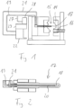
- the plastic injection molding machine shown comprises an injection mold 14 in which a mold cavity 15 is formed.
- the injection mold 14 is shown in the open state in which two halves of the injection mold 14 are spaced apart from each other. In the open state, an injection molded part can be removed from the mold cavity 15 of the injection mold 14.
- the injection mold 14 is brought into a closed state in which the two halves of the injection mold 14 are sealed together.
- a piston screw 16 By moving a piston screw 16 forwards, a Plastic material is introduced into the mold cavity 15 in a liquid state.
- the mold waits until the plastic material has hardened by cooling.
- the injection mold 14 is opened and the finished injection molded part is removed.
- the injection mold 14 comprises a mold core 17 that projects into the mold cavity 15 and defines a cylindrical recess in the injection molded part. To ensure a good structure and surface quality of the injection molded part in the area of the cylindrical recess, the cooling process in this area should be controlled in a targeted manner.
- the mold core 17 comprises, according to the enlarged illustration in Fig. 2 an evaporation chamber 18 in which a liquid is evaporated during the cooling process.
- a temperature corresponding to the evaporation temperature of the liquid is established, so that the cooling of the plastic material in the mold cavity 15 takes place under defined conditions.
- a supply line 19 is formed, which extends as a channel to the evaporation chamber 18.
- a capillary tube 20 is arranged, which has a diameter of approximately 1 mm.
- a liquid, for example water, is introduced under high pressure through the supply line 19 and the capillary tube 20 into the evaporation chamber 18.
- the pressure in the supply line 19 can be, for example, 15 bar.
- the pressure in the supply line 19 can drop above the capillary tube 20 between the transition from the supply line 19 into the capillary tube 20 and the mouth of the capillary tube 20 in the evaporation chamber 18.
- the temperature of the mold core 17 is higher than the evaporation temperature of the water, so that the water evaporates in the evaporation chamber 18.
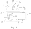
- the supply line 19 is according to Fig. 1 connected to a cooling device 22.
- the cooling device 22 comprises, according to the schematic representation in Fig. 3 a first pump 23, which is designed to pump the water under high pressure through the supply line 19 to the evaporation chamber 18.
- the steam and liquid residues are discharged from the evaporation chamber 18 through a discharge line 21 and returned to the cooling device 22.
- a condenser 24 is formed in the cooling device 22, in which the steam is condensed again.
- the condensation heat is removed from the condenser 24 via a heat exchanger 25, which is connected to a cold water circuit 26.
- the water collects in a lower section of the condenser 24 and can be sucked in again by the pump 23.
- a compressor 28 is also connected to the supply line 19 via a compressed air line 27. After completion of a cooling process and when the injection mold 14 is opened, a compressed air blast is passed through the supply line 19 in order to completely displace the steam and liquid residues from the evaporation chamber 18, so that defined starting conditions are present for the next cooling process.
- the water evaporates at 100 °C.
- a tool temperature of 90 °C is used, so that no cooling effect can be achieved by evaporating at 100 °C.
- the cooling device 22 of the injection molding machine according to the invention therefore comprises a pressure module 29 which is designed to apply a specific pressure in the evaporation chamber 18 in order to influence the evaporation temperature. This can be done in two directions. By reducing the pressure in the evaporation chamber 18, the evaporation temperature can be reduced. A reduced evaporation temperature can accelerate the cooling process, which can be used to shorten the cycle time when producing injection molded parts. By increasing the pressure in the evaporation chamber 18, the evaporation temperature is increased, which can slow down the cooling process of the plastic material. With certain plastic materials, the surface quality can be improved as a result.
- the pressure module 29 comprises according to Fig. 3 a vacuum pump 30 and an overpressure pump 31, between which it is possible to switch using a switch 32.
- the vacuum pump 30 and the overpressure pump 31 are second pumps in the sense of the invention. With the pumps 30, 31, a pressure different from atmospheric pressure can be applied in a pressure vessel 33. In order to enable pressure equalization with atmospheric pressure, the pressure vessel 33 is connected to the environment via a valve 35.
- the pressure from the pressure vessel 33 is transferred through an intermediate line 34, the interior of the condenser 24 and the discharge line 21 into the evaporation chamber 18. If the pressure vessel 33 is evacuated with the vacuum pump 33 to an absolute pressure of, for example, 200 mbar, then a pressure of 200 mbar is also present in the evaporation chamber 18. The water then evaporates at a temperature of 70 °C, so that the cooling process is accelerated. With a shorter Cooling process can help to shorten the cycle time when producing injection molded parts.
Landscapes
- Engineering & Computer Science (AREA)
- Mechanical Engineering (AREA)
- Manufacturing & Machinery (AREA)
- Physics & Mathematics (AREA)
- Thermal Sciences (AREA)
- Health & Medical Sciences (AREA)
- Oral & Maxillofacial Surgery (AREA)
- Moulds For Moulding Plastics Or The Like (AREA)
- Injection Moulding Of Plastics Or The Like (AREA)
Description
- Die Erfindung betrifft eine Vorrichtung zum Kühlen einer Gussform. Die Vorrichtung umfasst eine in der Gussform ausgebildete Verdampfungskammer. Mit einer ersten Pumpe wird der Verdampfungskammer eine Flüssigkeit zugeführt.
- Beim Herstellen von Gussteilen wird ein Gussmaterial in flüssigem Zustand einem Formhohlraum einer Gussform zugeführt. In dem Formhohlraum kühlt das Gussmaterial ab und geht in einen festen Zustand über. Es entsteht ein Gussteil, das eine dem Formhohlraum entsprechende Form hat. Die Gussform kann geöffnet werden, um das Gussteil aus der Form zu entnehmen.
- Um den Prozess der Abkühlung gezielt beeinflussen zu können, ist es bekannt, in bestimmten Bereichen des Gussformgehäuses eine Verdampfungskammer auszubilden. Eine Flüssigkeit, die unter hohem Druck zu der Verdampfungskammer geleitet wird, kann in der Verdampfungskammer entspannen, wodurch die Flüssigkeit verdampft. Die zum Verdampfen erforderliche Wärmemenge wird dem Gussformgehäuse und indirekt dem Gussmaterial in dem Formhohlraum entzogen, wodurch das Gussmaterial in diesem Abschnitt der Gussform gezielt gekühlt werden kann. Dieses Verfahren zum Kühlen einer Gussform wird auch als Jet-Cooling bezeichnet.
- Wenn der Gussform durch Verdampfen einer Flüssigkeit Wärme entzogen wird, so hat dies den Vorteil, dass sich aufgrund der konstanten Verdampfungstemperatur eine definierte Temperatur im Umfeld der Verdampfungskammer einstellt. Wird beispielsweise Wasser bei Atmosphärendruck verdampft, so liegt die Temperatur im Wesentlichen konstant bei etwa 100 °C.
- Die Patentschrift
EP 2 796 268 A1 stellt eine Vorrichtung zur Temperierung einer Werkzeugform vor, wobei ein Temperierfluidkreislauf zur Kühlung der Werkzeugform mittels Unterdruck-Siedekühlung eingerichtet ist. Die OffenlegungsschriftDE 1 758 140 A1 behandelt ein Verfahren und eine Vorrichtung zum Temperieren von Formwerzeugen, wobei eine Umlaufflüssigkeit durch ein regelbares Vakuum teilweise verdampft wird. InWO 2005/123357 A2 ist ein Verfahren zum Kontrollieren der Temperatur einer Gussform offenbart. - Der Erfindung liegt die Aufgabe zugrunde, eine Vorrichtung und ein Verfahren zum Kühlen einer Gussform vorzustellen, mit denen der Abkühlvorgang gezielt beeinflusst werden kann. Ausgehend vom genannten Stand der Technik wird die Aufgabe gelöst mit den Merkmalen der unabhängigen Ansprüche. Vorteilhafte Ausführungsformen sind in den Unteransprüchen angegeben.
- Die erfindungsgemäße Vorrichtung wird in Anspruch 1 und das erfindungsgemäße Verfahren in Anspruch 10 definiert. In den abhängigen Ansprüchen sind optionale Merkmale angegeben.
- Bei der erfindungsgemäßen Vorrichtung ist eine zweite Pumpe vorgesehen, um in der Verdampfungskammer einen von Atmosphärendruck abweichenden Druck anzulegen. Durch Einstellen des Drucks in der Verdampfungskammer kann die Temperatur beeinflusst werden, bei der die Flüssigkeit verdampft. Durch Erhöhen des Drucks in der Verdampfungskammer kann die Verdampfungstemperatur erhöht werden, durch Vermindern des Drucks in der Verdampfungskammer kann die Verdampfungstemperatur vermindert werden. Mit einer reduzierten Verdampfungstemperatur kann der Abkühlvorgang beschleunigt werden, was genutzt werden kann, um die Taktzeit beim Herstellen von Gussteilen zu verkürzen. Mit einer erhöhten Verdampfungstemperatur kann der Abkühlvorgang verlangsamt werden, wodurch sich bei bestimmten Gussteilen eine höhere Oberflächenqualität oder eine verbesserte Struktur des Materials erreichen lässt.
- Die Erfindung hat erkannt, dass es von Vorteil ist, die der Verdampfungskammer zugeführte Flüssigkeit mit der ersten Pumpe unter Druck zu stellen. Die erfindungsgemäße Kühlvorrichtung umfasst eine Zuleitung, die sich zu der Verdampfungskammer erstreckt. Um eine gezielte Kühlung zu ermöglichen, ist es von Vorteil, wenn die Flüssigkeit nicht in der Zuleitung verdampft, sondern erst beim Austritt der Flüssigkeit aus der Zuleitung in die Verdampfungskammer. Dies kann erreicht werden, indem die Flüssigkeit in der Zuleitung unter einem erhöhten Druck gesetzt wird. Der Druck, unter dem die Flüssigkeit in der Zuleitung steht ist deswegen erfindungsgemäß höher als der Druck in der Verdampfungskammer.
- Ein zu der Verdampfungskammer benachbarter Abschnitt der Zuleitung kann einen Durchmesser haben, der kleiner ist als der Durchmesser der Zuleitung in einem von der Verdampfungskammer weiter entfernten Abschnitt. Der zu der Verdampfungskammer benachbarte Abschnitt der Zuleitung stellt eine lokale Verengung in der Zuleitung dar und kann in der Verdampfungskammer münden. Im Betrieb der erfindungsgemäßen Vorrichtung kann über der lokalen Verengung eine Druckdifferenz anliegen. Die Druckdifferenz über der lokalen Verengung kann wenigstens 2%, vorzugsweise wenigstens 5%, weiter vorzugsweise wenigstens 10% der Gesamtdruckdifferenz ausmachen, die zwischen dem Ausgang der ersten Pumpe und dem Eingang der zweiten Pumpe anliegt. Der Weg, entlang dem die Druckdifferenz betrachtet wird, erstreckt sich von der ersten Pumpe über die lokale Verengung und die Verdampfungskammer zu der zweiten Pumpe. Vorzugsweise liegt die Druckdifferenz über der lokalen Verengung zwischen 30% und 90% der Gesamtdruckdifferenz. Hierdurch kann erreicht werden, dass die Flüssigkeit in der Zuleitung bis zu der Verengung einen so hohen Druck beibehält, dass sie nicht verdunstet. Die Zuleitung kann in dem die lokale Verengung bildenden, zu der Verdampfungskammer benachbarten Abschnitt einen Durchmesser zwischen 0,5 mm und 2 mm, vorzugsweise zwischen 0,8 mm und 1,2 mm haben. Dies bezieht sich auf eine Zuleitung mit kreisförmigen Querschnitt. Bei Zuleitungen mit anderem Querschnitt kann die Querschnittsfläche entsprechend sein.
- Um ein Verdampfen der Flüssigkeit in der Zuleitung auch dann zu verhindern, wenn die Temperatur der Zuleitung deutlich oberhalb der Verdampfungstemperatur in der Verdampfungskammer liegt, kann die Flüssigkeit in der Zuleitung unter einem entsprechend hohen Druck stehen. Erfindungsgemäß ist der Druck in der Zuleitung um wenigstens 5 bar, vorzugsweise um wenigstens 10 bar, weiter vorzugsweise um wenigstens 20 bar höher als der Druck in der Verdampfungskammer. Die erste Pumpe der erfindungsgemäßen Vorrichtung kann eine Flüssigkeitspumpe sein, die geeignet ist, die Flüssigkeit mit einem solchen Druck durch die Zuleitung zu fördern.
- Die erfindungsgemäße Vorrichtung umfasst eine Ableitung, durch die Reste der Flüssigkeit in verdampftem oder flüssigem Zustand aus der Verdampfungskammer abgeführt werden können. Um zu vermeiden, dass es beim Verdampfen der Flüssigkeit zu einem starken Druckanstieg in der Verdampfungskammer kommt, kann die Ableitung einen größeren Querschnitt haben als die Zuleitung.
- Die zweite Pumpe, mit der gemäß der Erfindung der Druck in der Verdampfungskammer eingestellt wird, ist an die Ableitung angeschlossen. Dies bedeutet, dass der von der zweiten Pumpe aufgebaute Druck über die Ableitung oder über einen Abschnitt der Ableitung zu der Verdampfungskammer übertragen wird.
- Die erfindungsgemäße Vorrichtung kann an einem Kondensator angeschlossen sein, in dem verdampfte Flüssigkeitsmengen aus der Verdampfungskammer wieder kondensiert werden. Der Kondensator kann einen Wärmetauscher umfassen, mit dem überschüssige Wärme abgeführt wird. Als Kühlmedium für den Kondensator kann beispielsweise Wasser verwendet werden.
- Der Kondensator kann einen Behälter umfassen, dessen unterer Bereich mit Flüssigkeit gefüllt ist. Die erste Pumpe kann an den unteren Bereich des Behälters angeschlossen sein. Wenn die erste Pumpe in Betrieb ist, wird Flüssigkeit aus dem unteren Bereich des Behälters angesaugt und durch die Zuleitung zu der Verdampfungskammer gefördert.
- Die zweite Pumpe, mit der der gewünschte Druck in der Verdampfungskammer erzeugt wird, kann oberhalb des Flüssigkeitspegels an den Behälter des Kondensators angeschlossen sein. Ein von der zweiten Pumpe erzeugter Unterdruck oder Überdruck wird durch den Behälter des Kondensators und die Ableitung zu der Verdampfungskammer übertragen. Zwischen der zweiten Pumpe und der Verdampfungskammer kann ein Druckspeicher angeordnet sein, so dass der gewünschte Druck in der Verdampfungskammer auch dann aufrechterhalten werden kann, wenn die zweite Pumpe nicht in Betrieb ist.
- Mit der Ableitung kann ein Ventil verbunden sein, das im geöffneten Zustand eine Verbindung zwischen der Ableitung und Atmosphärendruck herstellt. Bei geöffnetem Ventil findet ein Druckausgleich zwischen der Ableitung und der Umgebung statt, so dass sich in der Ableitung Atmosphärendruck einstellt. Es kann zweckmäßig sein, zwischen zwei Zyklen, in denen in der Verdampfungskammer zum Zwecke der Kühlungsflüssigkeit verdampft wird, einen Ausgleich auf Atmosphärendruck durchzuführen, um ein Verdampfen von Flüssigkeitsmengen während solcher Phasen zu unterbinden, in denen keine Kühlwirkung gewünscht ist.
- Das Ventil kann an einer geeigneten Stelle zwischen der Verdampfungskammer und der zweiten Pumpe angeordnet sein, beispielsweise an der Ableitung, an dem Kondensator oder an dem Druckspeicher.
- Die erfindungsgemäße Kühlvorrichtung kann mit einem Gasanschluss ausgestattet sein, über den ein Gas, insbesondere Luft, in die Verdampfungskammer eingelassen werden kann, um Flüssigkeitsreste aus der Verdampfungskammer auszublasen. Das Entfernen von Flüssigkeitsresten aus der Verdampfungskammer kann durchgeführt werden, um für den nächsten Kühlvorgang eine definierte Ausgangssituation zu schaffen, in der die Verdampfungskammer ausschließlich mit Gas gefüllt ist. Der Gasanschluss kann beispielsweise direkt an der Verdampfungskammer oder an einem Abschnitt der Zuleitung angeschlossen sein.
- Ist der Gasanschluss geöffnet, so kann das Gas unter dem Einfluss einer Druckdifferenz in die Verdampfungskammer eintreten. Liegt in der Verdampfungskammer ein Unterdruck an, so kann die Druckdifferenz gegenüber Atmosphärendruck ausreichen, um das Gas anzutreiben. Möglich ist auch, dass das Gas unter einem Überdruck gegenüber Atmosphärendruck in den Gasanschluss eingeleitet wird. Die Flüssigkeitszufuhr durch die Zuleitung ist vorzugsweise unterbrochen, während Gas in die Verdampfungskammer eintritt.
- Die zweite Pumpe ist in einer Ausführungsform eine Vakuumpumpe, die dazu ausgelegt ist, in der Verdampfungskammer einen Druck anzulegen, der kleiner ist als Atmosphärendruck. Der absolute Druck in der Verdampfungskammer, wenn die zweite Pumpe in Betrieb ist, kann beispielsweise zwischen 50 mbar und 800 mbar, vorzugsweise zwischen 100 mbar und 500 mbar liegen. Wird der Druck in der Verdampfungskammer auf beispielsweise 200 mbar reduziert, so verdampft das Wasser bereits bei 70 °C.
- Die Verwendung einer Vakuumpumpe ist zweckmäßig, wenn der Abkühlvorgang durch die Erfindung beschleunigt werden soll.
- Die Verwendung einer Vakuumpumpe als zweite Pumpe ist außerdem zweckmäßig, wenn der Gussvorgang bei Werkzeugtemperaturen unterhalb von 100 °C erfolgt. Durch Verdampfen von Wasser bei Atmosphärendruck kann dann keine Kühlwirkung erzielt werden. Mit Werkzeugtemperaturen unterhalb von 100 °C wird beispielsweise beim Spritzgießen bestimmter Kunststoffe gearbeitet, wie etwa Polyoxymethylen (POM), Polyamid (PA) oder Polybutylenterephthalat (PBT).
- In einer anderen Ausführungsform ist die zweite Pumpe eine Überdruckpumpe, die dazu ausgelegt ist, in der Verdampfungskammer einen Druck anzulegen, der größer ist als Atmosphärendruck. Der absolute Druck in der Verdampfungskammer, wenn die zweite Pumpe in Betrieb ist, kann beispielsweise zwischen 5 bar und 15 bar liegen. Die Verwendung einer Überdruckpumpe als zweite Pumpe kann zweckmäßig sein, wenn der Abkühlvorgang durch die Erfindung verlangsamt werden soll.
- Wird mit Werkzeugtemperaturen deutlich oberhalb von 100 °C gearbeitet, so wird die Gussform lokal sehr stark gekühlt, wenn in der Verdampfungskammer Wasser bei Atmosphärendruck verdampft wird. Eine solche starke lokale Kühlung kann unerwünschte Effekte auf die Struktur des Materials in der Gussform haben oder zu einer verminderten Oberflächenqualität führen. Bei einer Erhöhung des absoluten Drucks in der Verdampfungskammer auf einen Wert von beispielsweise 10 bar, verdampft das Wasser erst bei einer Temperatur von etwa 200 °C. Das Material in der Gussform kann auf diese Weise einer weniger abrupten Abkühlung ausgesetzt werden. Ein verlangsamter Abkühlvorgang kann beispielsweise beim Spritzgießen bestimmter Kunststoffe gewünscht sein. Beispiele für solche Kunststoffe sind Polyacrylsäure (PAA), Polyphthalamide (PPA) oder Polyphenylensulfid (PPS).
- Die erfindungsgemäße Kühlvorrichtung kann so gestaltet sein, dass sie eine Vakuumpumpe und eine Überdruckpumpe umfasst. Es kann ein Umschalter vorgesehen sein, um zwischen der Vakuumpumpe und der Überdruckpumpe umzuschalten, so dass je nach gewünschter Kühltemperatur in der Verdampfungskammer zwischen der Vakuumpumpe und der Überdruckpumpe umgeschaltet werden kann.
- Die Gussform der erfindungsgemäßen Vorrichtung kann eine Mehrzahl von Verdampfungskammern umfassen. Den Verdampfungskammern kann synchron miteinander oder unabhängig voneinander Flüssigkeit zum Verdampfen zugeführt werden.
- Die erste Pumpe und die zweite Pumpe der erfindungsgemäßen Vorrichtung können als separate bauliche Einheiten ausgebildet sein. Möglich ist auch, dass es sich bei der ersten Pumpe und der zweiten Pumpe um funktionale Elemente innerhalb einer einzelnen Pumpeneinheit handelt.
- Die Erfindung betrifft außerdem eine Kunststoff-Spritzgussmaschine, bei der eine Spritzgussform mit einer solchen Vorrichtung gekühlt wird.
- Die Erfindung betrifft außerdem ein Verfahren zum Kühlen einer Gussform, bei dem eine Flüssigkeit zu einer in der Gussform ausgebildeten Verdampfungskammer zugeführt wird, um die Flüssigkeit in der Verdampfungskammer zu verdampfen. Bei dem Verfahren wird in der Verdampfungskammer ein von Atmosphärendruck abweichender Druck angelegt. Dabei wird die Flüssigkeit in der Zuleitung unter einen erhöhten Druck gesetzt, sodass die Flüssigkeit nicht in der Zuleitung verdampft. Die Erfindung betrifft außerdem ein Verfahren zum Herstellen eines Kunststoff-Spritzgussteils, bei dem eine Spritzgussform nach diesem Verfahren gekühlt wird.
- Das Verfahren kann mit weiteren Merkmalen fortgebildet werden, die im Zusammenhang der erfindungsgemäßen Vorrichtung beschrieben sind. Die Vorrichtung kann mit weiteren Merkmalen fortgebildet werden, die im Zusammenhang des erfindungsgemäßen Verfahrens beschrieben sind.
- Die Erfindung wird nachfolgend unter Bezugnahme auf die beigefügten Zeichnungen anhand vorteilhafter Ausführungsformen beispielhaft beschrieben. Es zeigen:
- Fig. 1:
- eine schematische Darstellung einer erfindungsgemäßen Kunststoff-Spritzgussmaschine;
- Fig. 2:
- ein Detail aus
Fig. 1 in vergrößerter Darstellung; - Fig. 3:
- eine schematische Darstellung einer erfindungsgemäßen Vorrichtung zum Kühlen der Gussform.
- Eine in
Fig. 1 gezeigte Kunststoff-Spritzgussmaschine umfasst eine Spritzgussform 14, in der ein Formhohlraum 15 ausgebildet ist. Die Spritzgussform 14 ist im geöffneten Zustand gezeigt, in dem zwei Hälften der Spritzgussform 14 voneinander beabstandet sind. Im geöffneten Zustand kann ein Spritzgussteil aus dem Formhohlraum 15 der Spritzgussform 14 entnommen werden. - Für den nächsten Spritzgussvorgang wird die Spritzgussform 14 in einen geschlossenen Zustand gebracht, in dem die beiden Hälften der Spritzgussform 14 dicht miteinander abschließen. Durch eine Vorwärts-Bewegung einer Kolbenschnecke 16 wird ein Kunststoffmaterial in flüssigem Zustand in den Formhohlraum 15 eingebracht. Es wird gewartet, bis das Kunststoffmaterial durch Abkühlen ausgehärtet ist. Die Spritzgussform 14 wird geöffnet und das fertige Spritzgussteil wird entnommen.
- Die Spritzgussform 14 umfasst einen in den Formhohlraum 15 vorspringenden Formkern 17, durch den eine zylinderförmige Vertiefung in dem Spritzgussteil definiert wird. Für eine gute Struktur und Oberflächenqualität des Spritzgussteils im Bereich der zylinderförmigen Vertiefung soll der Abkühlvorgang in diesem Bereich gezielt gesteuert werden.
- Der Formkern 17 umfasst dazu gemäß der vergrößerten Darstellung in
Fig. 2 eine Verdampfungskammer 18, in der während des Abkühlvorgangs eine Flüssigkeit verdampft wird. In der Verdampfungskammer 18 stellt sich eine der Verdampfungstemperatur der Flüssigkeit entsprechende Temperatur ein, so dass das Abkühlen des Kunststoffmaterials in dem Formhohlraum 15 unter definierten Bedingungen erfolgt. - In dem Formkern 17 ist gemäß der vergrößerten Darstellung in
Fig. 2 eine Zuleitung 19 ausgebildet, die sich als Kanal bis zu der Verdampfungskammer 18 erstreckt. In einem vorderen Abschnitt der Zuleitung 19 ist ein Kapillarröhrchen 20 angeordnet, dass einen Durchmesser von etwa 1 mm hat. - Eine Flüssigkeit, beispielsweise Wasser, wird unter hohem Druck durch die Zuleitung 19 und das Kapillarröhrchen 20 hindurch in die Verdampfungskammer 18 eingebracht. Der Druck in der Zuleitung 19 kann beispielsweise bei 15 bar liegen. Der Druck in der Zuleitung 19 kann, zwischen dem Übergang von der Zuleitung 19 in das Kapillarröhrchen 20 und der Mündung des Kapillarröhrchens 20 in der Verdampfungskammer 18, über dem Kapillarröhrchen 20 abfallen. Die Temperatur des Formkerns 17 ist höher als die Verdampfungstemperatur des Wassers, so dass das Wasser in der Verdampfungskammer 18 verdampft.
- Die Zuleitung 19 ist gemäß
Fig. 1 an eine Kühlvorrichtung 22 angeschlossen. Die Kühlvorrichtung 22 umfasst gemäß der schematischen Darstellung inFig. 3 eine erste Pumpe 23, die dazu ausgelegt ist, das Wasser unter hohem Druck durch die Zuleitung 19 zu der Verdampfungskammer 18 zu pumpen. Durch eine Ableitung 21 werden der Dampf und Flüssigkeitsreste aus der Verdampfungskammer 18 abgeführt und zu der Kühlvorrichtung 22 zurückgeleitet. - In der Kühlvorrichtung 22 ist ein Kondensator 24 ausgebildet, in dem der Dampf wieder kondensiert wird. Über einen Wärmetauscher 25, der an einem Kaltwasser-Kreislauf 26 angeschlossen ist, wird die Kondensationswärme aus dem Kondensator 24 abgeführt. In einem unteren Abschnitt des Kondensators 24 sammelt sich das Wasser und kann von der Pumpe 23 erneut angesaugt werden.
- An die Zuleitung 19 ist über eine Druckluftleitung 27 außerdem ein Kompressor 28 angeschlossen. Nach Abschluss eines Kühlvorgangs und wenn die Spritzgussform 14 geöffnet ist, wird ein Druckluftstoß durch die Zuleitung 19 geleitet, um den Dampf und Flüssigkeitsreste vollständig aus der Verdampfungskammer 18 zu verdrängen, so dass definierte Ausgangsbedingungen für den nächsten Abkühlvorgang vorliegen.
- Liegt in der Verdampfungskammer 18 Atmosphärendruck an, so verdampft das Wasser bei 100 °C. Im vorliegenden Ausführungsbeispiel wird mit einer Werkzeugtemperatur von 90 °C gearbeitet, so dass durch ein Verdampfen bei 100 °C keine Kühlwirkung erzielt werden kann.
- Die Kühlvorrichtung 22 der erfindungsgemäßen Spritzgussmaschine umfasst deswegen ein Druckmodul 29, das dazu ausgelegt ist, in der Verdampfungskammer 18 gezielt einem bestimmten Druck anzulegen, um die Verdampfungstemperatur zu beeinflussen. Dies kann in zwei Richtungen geschehen. Durch Reduzieren des Drucks in der Verdampfungskammer 18 kann die Verdampfungstemperatur reduziert werden. Durch eine reduzierte Verdampfungstemperatur kann der Kühlvorgang beschleunigt werden, was genutzt werden kann, um die Taktzeit beim Herstellen von Spritzgussteilen zu verkürzen. Durch Erhöhen des Drucks in der Verdampfungskammer 18 wird die Verdampfungstemperatur erhöht, wodurch der Abkühlvorgang des Kunststoffmaterials verlangsamt werden kann. Bei bestimmten Kunstmaterialien lässt sich dadurch die Oberflächenqualität verbessern.
- Das Druckmodul 29 umfasst gemäß
Fig. 3 eine Vakuumpumpe 30 und eine Überdruckpumpe 31, zwischen denen mit einem Umschalter 32 umgeschaltet werden kann. Die Vakuumpumpe 30 und die Überdruckpumpe 31 sind zweite Pumpen im Sinne der Erfindung. Mit den Pumpen 30, 31 kann ein von Atmosphärendruck abweichender Druck in einem Druckbehälter 33 angelegt werden. Um einen Druckausgleich mit Atmosphärendruck zu ermöglichen, ist der Druckbehälter 33 über ein Ventil 35 mit der Umgebung verbunden. - Der Druck aus dem Druckbehälter 33 überträgt sich durch eine Zwischenleitung 34, den Innenraum des Kondensators 24 sowie die Ableitung 21 bis in die Verdampfungskammer 18. Wird der Druckbehälter 33 mit der Vakuumpumpe 33 auf einen absoluten Druck von beispielsweise 200 mbar evakuiert, so liegt auch in der Verdampfungskammer 18 ein Druck von 200 mbar an. Das Wasser verdampft dann bereits bei einer Temperatur von 70 °C, so dass der Abkühlvorgang beschleunigt wird. Mit einem kürzeren Abkühlvorgang kann dazu beigetragen werden, die Taktzeit beim Herstellen von Spritzgussteilen zu verkürzen.
- Wird mit der Überdruckpumpe 31 ein Überdruck in dem Druckbehälter 33 angelegt, so überträgt auch dieser sich in die Verdampfungskammer 18. Ein erhöhter Druck in der Verdampfungskammer 18 führt zu einer erhöhten Verdampfungstemperatur und damit zu einer Verlangsamung des Abkühlvorgangs. Durch einen langsameren Abkühlvorgang lässt sich bei bestimmten Kunststoffmaterialien eine verbesserte Oberflächenqualität des Spritzgussteils erreichen.
Claims (11)
- Vorrichtung zum Kühlen einer Gussform (14), umfassend eine Gussform (14), in der ein Formhohlraum (15) ausgebildet ist, wobei in der Gussform (14) eine Verdampfungskammer (18) ausgebildet ist, mit einer ersten Pumpe (23), um eine Flüssigkeit zu der Verdampfungskammer (18) zuzuführen, und mit einer zweiten Pumpe (30, 31), um in der Verdampfungskammer (18) einen von Atmosphärendruck abweichenden Druck anzulegen, mit einer Zuleitung (19), die sich zu der Verdampfungskammer (18) erstreckt, wobei die Flüssigkeit in der Zuleitung (19) unter einen erhöhten Druck gesetzt wird, sodass die Flüssigkeit nicht in der Zuleitung (19) verdampft, wobei die erste Pumpe (23) dazu ausgelegt ist, die der Verdampfungskammer (18) zugeführte Flüssigkeit in der Zuleitung (19) unter einem Druck zu fördern, der um wenigstens 5 bar höher ist als der Druck in der Verdampfungskammer (18), und wobei ein zu der Verdampfungskammer (18) benachbarter Abschnitt der Zuleitung (19) eine lokale Verengung in der Zuleitung (19) bildet, wobei sich eine Ableitung von der Verdampfungskammer erstreckt, wobei die zweite Pumpe an die Ableitung angeschlossen ist und wobei die Vorrichtung dazu ausgebildet ist, dass der von der zweiten Pumpe aufgebaute Druck über die Ableitung oder über einen Abschnitt der Ableitung zu der Verdampfungskammer übertragen wird.
- Vorrichtung nach Anspruch 1, dadurch gekennzeichnet, dass die Zuleitung (19) in dem die lokale Verengung bildenden, zu der Verdampfungskammer benachbarten Abschnitt (20) einen Durchmesser zwischen 0,5 mm und 2 mm, vorzugsweise zwischen 0,8 mm und 1,2 mm hat.
- Vorrichtung nach einem der Ansprüche 1 oder 2, dadurch gekennzeichnet, dass die erste Pumpe dazu ausgelegt ist, die der Verdampfungskammer (18) zugeführte Flüssigkeit in der Zuleitung (19) unter einem Druck zu fördern, der um wenigstens 10 bar, weiter vorzugsweise um wenigstens 20 bar höher ist als der Druck in der Verdampfungskammer (18).
- Vorrichtung nach einem der Ansprüche 1 bis 3, dadurch gekennzeichnet, dass die Ableitung (21) einen größeren Querschnitt hat als die Zuleitung (19).
- Vorrichtung nach einem der Ansprüche 1 bis 4, gekennzeichnet durch einen Kondensator (24), um verdampfte Flüssigkeitsmengen aus der Verdampfungskammer (18) zu kondensieren.
- Vorrichtung nach einem der Ansprüche 1 bis 5, gekennzeichnet durch einen Gasanschluss (27), um der Verdampfungskammer (18) ein Gas zuzuführen.
- Vorrichtung nach einem der Ansprüche 1 bis 6, dadurch gekennzeichnet, dass die zweite Pumpe eine Vakuumpumpe (30) ist.
- Vorrichtung nach einem der Ansprüche 1 bis 7, dadurch gekennzeichnet, dass die zweite Pumpe eine Überdruckpumpe (31) ist.
- Kunststoff-Spritzgussmaschine mit einer Spritzgussform (14) und mit einer Vorrichtung zum Kühlen der Spritzgussform (14), wobei die Vorrichtung zum Kühlen nach einem der Ansprüche 1 bis 8, ausgebildet ist.
- Verfahren zum Kühlen einer Gussform (14), bei dem in einer Gussform (14) ein Formhohlraum (15) augebildet ist, bei dem in der Gussform (14) eine Verdampfungskammer (18) ausgebildet ist, bei dem eine Flüssigkeit durch eine Zuleitung (19) zu der Verdampfungskammer (18) zugeführt wird, um die Flüssigkeit in der Verdampfungskammer (18) zu verdampfen, bei dem Reste der Flüssigkeit in verdampftem oder flüssigem Zustand über eine Ableitung (21) aus der Verdampfungskammer (18) abgeführt werden, und bei dem über eine zweite Pumpe ein durch die zweite Pumpe aufgebauter Druck über die Ableitung (21) oder einen Abschnitt der Ableitung (21) in der Verdampfungskammer (18) angelegt wird, wobei in der Verdampfungskammer ein von Atmosphärendruck abweichender Druck angelegt wird, wobei die Flüssigkeit in einer Zuleitung (19) zu der Verdampfungskammer (18) unter einen erhöhten Druck gesetzt wird, sodass die Flüssigkeit nicht in der Zuleitung (19) verdampft, wobei der Druck in der Zuleitung (19) um wenigstens 5 bar höher ist als der Druck in der Verdampfungskammer (18) und wobei ein zu der Verdampfungskammer (18) benachbarter Abschnitt der Zuleitung (19) eine lokale Verengung in der Zuleitung (19) bildet.
- Verfahren zum Herstellen eines Kunststoff-Spritzgussteils, beim dem eine Spritzgussform (14) mit dem Verfahren nach Anspruch 10 gekühlt wird.
Applications Claiming Priority (2)
| Application Number | Priority Date | Filing Date | Title |
|---|---|---|---|
| EP18156455.0A EP3524403A1 (de) | 2018-02-13 | 2018-02-13 | Vorrichtung und verfahren zum kühlen einer gussform |
| PCT/EP2019/053425 WO2019158521A1 (de) | 2018-02-13 | 2019-02-12 | Vorrichtung und verfahren zum kühlen einer gussform |
Publications (3)
| Publication Number | Publication Date |
|---|---|
| EP3752335A1 EP3752335A1 (de) | 2020-12-23 |
| EP3752335B1 true EP3752335B1 (de) | 2025-01-22 |
| EP3752335C0 EP3752335C0 (de) | 2025-01-22 |
Family
ID=61198754
Family Applications (2)
| Application Number | Title | Priority Date | Filing Date |
|---|---|---|---|
| EP18156455.0A Withdrawn EP3524403A1 (de) | 2018-02-13 | 2018-02-13 | Vorrichtung und verfahren zum kühlen einer gussform |
| EP19703357.4A Active EP3752335B1 (de) | 2018-02-13 | 2019-02-12 | Vorrichtung und verfahren zum kühlen einer gussform |
Family Applications Before (1)
| Application Number | Title | Priority Date | Filing Date |
|---|---|---|---|
| EP18156455.0A Withdrawn EP3524403A1 (de) | 2018-02-13 | 2018-02-13 | Vorrichtung und verfahren zum kühlen einer gussform |
Country Status (5)
| Country | Link |
|---|---|
| US (1) | US12042970B2 (de) |
| EP (2) | EP3524403A1 (de) |
| JP (1) | JP7264335B2 (de) |
| KR (1) | KR20200118427A (de) |
| WO (1) | WO2019158521A1 (de) |
Families Citing this family (5)
| Publication number | Priority date | Publication date | Assignee | Title |
|---|---|---|---|---|
| JP7759107B2 (ja) * | 2019-11-29 | 2025-10-23 | マルコム バリー ジェームズ | 流体相変化熱管理装置および方法 |
| CN112248386A (zh) * | 2020-09-09 | 2021-01-22 | 芜湖友恒模具有限公司 | 一种注塑模具的散热装置 |
| FR3136841B1 (fr) * | 2022-06-20 | 2024-05-31 | Pinette Emidecau Ind | Dispositif de refroidissement par fluide d’une surface chaude et plaque de presse ou moule associe |
| EP4594070A1 (de) | 2022-09-29 | 2025-08-06 | G.A. Röders Holding GmbH & Co. KG | KUNSTSTOFFSPRITZGIEßMASCHINE UND VERFAHREN ZUM BETREIBEN EINER KUNSTSTOFFSPRITZGIEßMASCHINE |
| EP4563320A1 (de) | 2023-11-29 | 2025-06-04 | G.A. Röders Holding GmbH & Co. KG | Verfahren zum überwachen eines spritzgussvorgangs, kunststoff-spritzgiessmaschine |
Citations (1)
| Publication number | Priority date | Publication date | Assignee | Title |
|---|---|---|---|---|
| WO2005123357A2 (en) * | 2004-06-10 | 2005-12-29 | Advanced Plastics Technologies Luxembourg S.A. | Methods and systems for cooling molds |
Family Cites Families (14)
| Publication number | Priority date | Publication date | Assignee | Title |
|---|---|---|---|---|
| DE1758140A1 (de) * | 1968-04-09 | 1971-05-13 | Albers August | Verfahren und Vorrichtung zur Temperierung von Formwerkzeugen |
| DE3322312A1 (de) * | 1983-06-21 | 1985-01-03 | Linde Ag, 6200 Wiesbaden | Verfahren und vorrichtung zum herstellen von spritzgiessteilen |
| JPH0539744U (ja) * | 1991-10-18 | 1993-05-28 | 曙ブレーキ工業株式会社 | 熱間金型の水冷装置 |
| JP2538476B2 (ja) * | 1992-02-12 | 1996-09-25 | リョービ株式会社 | 金型冷却装置 |
| JPH09136325A (ja) * | 1995-11-15 | 1997-05-27 | Uchihama Kasei Kk | 金型装置 |
| JPH09308954A (ja) * | 1996-05-17 | 1997-12-02 | Toyota Motor Corp | 金型の冷却方法 |
| JP2000015421A (ja) | 1998-07-03 | 2000-01-18 | Nec Corp | 金型冷却装置 |
| JP4021314B2 (ja) | 2002-12-10 | 2007-12-12 | 羽根エンジニアリング株式会社 | 発泡樹脂成形における金型冷却方法及びその装置 |
| DE102008000452A1 (de) * | 2008-02-29 | 2009-09-03 | Stemke, Gudrun | Kühlmittelverteilung zur Werkzeugkühlung |
| DE102008062433B3 (de) * | 2008-12-17 | 2010-05-06 | Werkzeugbau Siegfried Hofmann Gmbh | Verfahren zur zyklusabhängigen Temperierung eines Spritzgieß- oder Thermoformwerkzeuges |
| JP2012121245A (ja) | 2010-12-09 | 2012-06-28 | Matsui Mfg Co | 金型冷却装置及びこれを備えた金型冷却システム |
| JP5726845B2 (ja) | 2012-12-13 | 2015-06-03 | 本田技研工業株式会社 | 鋳造金型冷却装置及び鋳造金型冷却方法 |
| EP2796268A1 (de) * | 2013-04-24 | 2014-10-29 | Robamat Automatisierungstechnik GmbH | Vorrichtung und Verfahren zur Temperierung einer Werkzeugform |
| JP6086895B2 (ja) | 2014-12-12 | 2017-03-01 | ジヤトコ株式会社 | 金型の冷却装置 |
-
2018
- 2018-02-13 EP EP18156455.0A patent/EP3524403A1/de not_active Withdrawn
-
2019
- 2019-02-12 WO PCT/EP2019/053425 patent/WO2019158521A1/de not_active Ceased
- 2019-02-12 JP JP2020542100A patent/JP7264335B2/ja active Active
- 2019-02-12 KR KR1020207022671A patent/KR20200118427A/ko not_active Ceased
- 2019-02-12 EP EP19703357.4A patent/EP3752335B1/de active Active
- 2019-02-12 US US16/969,885 patent/US12042970B2/en active Active
Patent Citations (1)
| Publication number | Priority date | Publication date | Assignee | Title |
|---|---|---|---|---|
| WO2005123357A2 (en) * | 2004-06-10 | 2005-12-29 | Advanced Plastics Technologies Luxembourg S.A. | Methods and systems for cooling molds |
Non-Patent Citations (1)
| Title |
|---|
| IP COM ET AL: "04/05/2020 Evaporative cooling of injection mold inserts ? What can I type? Search using keywords with optional Boolean syntax Keyword Search Concept Search ? Add Date Range Browse Prior Art Database Quick Links Click to Preview Evaporative cooling of injection mold insertsCOM DISCLOSURE NUMBER: IPC", 1 January 2020 (2020-01-01), XP055691205, Retrieved from the Internet <URL:https://ip.com/> * |
Also Published As
| Publication number | Publication date |
|---|---|
| EP3752335A1 (de) | 2020-12-23 |
| WO2019158521A1 (de) | 2019-08-22 |
| US12042970B2 (en) | 2024-07-23 |
| JP2021513472A (ja) | 2021-05-27 |
| US20200406520A1 (en) | 2020-12-31 |
| EP3752335C0 (de) | 2025-01-22 |
| JP7264335B2 (ja) | 2023-04-25 |
| EP3524403A1 (de) | 2019-08-14 |
| KR20200118427A (ko) | 2020-10-15 |
Similar Documents
| Publication | Publication Date | Title |
|---|---|---|
| EP3752335B1 (de) | Vorrichtung und verfahren zum kühlen einer gussform | |
| DE102011078167B4 (de) | Verfahren zur Temperierung eines Spritzgießwerkzeugs | |
| EP0336225A2 (de) | Verfahren und Vorrichtung zum Herstellen von Formlingen aus expandierbaren Kunststoffpartikeln | |
| DE102015220951B4 (de) | Wasserkühlvorrichtung für ein Schleudergussgerät | |
| DE19903682A1 (de) | Hohlkörper aus polymeren Werkstoffen | |
| WO2019025087A1 (de) | Vorrichtung und verfahren zur herstellung eines partikelschaumstoffteils | |
| EP3059062A1 (de) | Temperiervorrichtung zum variothermen oder konventionellen temperieren von formwerkzeugen | |
| DE102009012481B3 (de) | Spritzgießmaschine zur Verarbeitung von Kunststoffen | |
| EP1390190A1 (de) | Verfahren und vorrichtung zur druckregelung bei einem einschneckenentgasungsextruder oder einem kaskadenextruder | |
| DE102010042759A1 (de) | Verfahren zur Herstellung von Kunststoff-Formteilen | |
| DE112012004392B4 (de) | Verfahren und Vorrichtung zur Einkapselung elektronischer Bauteile mithilfe eines eine Phasenänderung durchlaufenden Reduktionsmaterials | |
| EP2136982B1 (de) | Form und verfahren zur herstellung von formhäuten und formkörpern aus kunststoff | |
| DE112018007413B4 (de) | Verfahren zur herstellung eines hohlen, aus harz gegossenen gegenstandes und vorrichtung zur herstellung eines hohlen, aus harz gegossenen gegenstandes | |
| EP0499139B1 (de) | Einrichtung zum Beaufschlagen von mehreren Formen mit einem oder mehreren Fluiden und zum Temperieren der Formen für die Kunststoffverarbeitung | |
| EP2043834B1 (de) | Spritzgiessverfahren | |
| WO2001019590A1 (de) | Verfahren und vorrichtung zum temperieren von formwerkzeugen von spritzgussmaschinen | |
| EP2298530B1 (de) | Vorrichtung und Verfahren zur Temperierung eines Spritzgießwerkzeugs | |
| EP0033901B1 (de) | Verfahren und Vorrichtung zum Druckgiessen von schmelzflüssigem Metall | |
| DE19637347B4 (de) | Verfahren zum Herstellen eines Gußteils | |
| WO2014075756A1 (de) | Verfahren zum temperieren eines spritzpresswerkzeugs und spritzpresswerkzeug | |
| DE4444579C2 (de) | Spritzgießverfahren zum Herstellen von Kunststoffbauteilen | |
| EP1183119B1 (de) | Werkstück-erzeugungsvorrichtung | |
| WO2024068874A1 (de) | KUNSTSTOFFSPRITZGIEßMASCHINE UND VERFAHREN ZUM BETREIBEN EINER KUNSTSTOFFSPRITZGIEßMASCHINE | |
| EP2185336B1 (de) | Kalibriervorrichtung mit Trockenkalibrierstrecke und Nasskalibrierstrecke und entsprechendes Kalibrierverfahren | |
| DE102023004786A1 (de) | Plastifizier- und Einspritzvorrichtung zum Herstellen von Spritzgussbauteilen |
Legal Events
| Date | Code | Title | Description |
|---|---|---|---|
| STAA | Information on the status of an ep patent application or granted ep patent |
Free format text: STATUS: UNKNOWN |
|
| STAA | Information on the status of an ep patent application or granted ep patent |
Free format text: STATUS: THE INTERNATIONAL PUBLICATION HAS BEEN MADE |
|
| PUAI | Public reference made under article 153(3) epc to a published international application that has entered the european phase |
Free format text: ORIGINAL CODE: 0009012 |
|
| STAA | Information on the status of an ep patent application or granted ep patent |
Free format text: STATUS: REQUEST FOR EXAMINATION WAS MADE |
|
| 17P | Request for examination filed |
Effective date: 20200819 |
|
| AK | Designated contracting states |
Kind code of ref document: A1 Designated state(s): AL AT BE BG CH CY CZ DE DK EE ES FI FR GB GR HR HU IE IS IT LI LT LU LV MC MK MT NL NO PL PT RO RS SE SI SK SM TR |
|
| AX | Request for extension of the european patent |
Extension state: BA ME |
|
| DAV | Request for validation of the european patent (deleted) | ||
| DAX | Request for extension of the european patent (deleted) | ||
| STAA | Information on the status of an ep patent application or granted ep patent |
Free format text: STATUS: EXAMINATION IS IN PROGRESS |
|
| 17Q | First examination report despatched |
Effective date: 20211118 |
|
| P01 | Opt-out of the competence of the unified patent court (upc) registered |
Effective date: 20230515 |
|
| GRAP | Despatch of communication of intention to grant a patent |
Free format text: ORIGINAL CODE: EPIDOSNIGR1 |
|
| STAA | Information on the status of an ep patent application or granted ep patent |
Free format text: STATUS: GRANT OF PATENT IS INTENDED |
|
| INTG | Intention to grant announced |
Effective date: 20240930 |
|
| GRAS | Grant fee paid |
Free format text: ORIGINAL CODE: EPIDOSNIGR3 |
|
| GRAA | (expected) grant |
Free format text: ORIGINAL CODE: 0009210 |
|
| STAA | Information on the status of an ep patent application or granted ep patent |
Free format text: STATUS: THE PATENT HAS BEEN GRANTED |
|
| AK | Designated contracting states |
Kind code of ref document: B1 Designated state(s): AL AT BE BG CH CY CZ DE DK EE ES FI FR GB GR HR HU IE IS IT LI LT LU LV MC MK MT NL NO PL PT RO RS SE SI SK SM TR |
|
| REG | Reference to a national code |
Ref country code: GB Ref legal event code: FG4D Free format text: NOT ENGLISH |
|
| REG | Reference to a national code |
Ref country code: CH Ref legal event code: EP |
|
| REG | Reference to a national code |
Ref country code: IE Ref legal event code: FG4D Free format text: LANGUAGE OF EP DOCUMENT: GERMAN |
|
| REG | Reference to a national code |
Ref country code: DE Ref legal event code: R096 Ref document number: 502019012846 Country of ref document: DE |
|
| U01 | Request for unitary effect filed |
Effective date: 20250213 |
|
| P04 | Withdrawal of opt-out of the competence of the unified patent court (upc) registered |
Free format text: CASE NUMBER: APP_7824/2025 Effective date: 20250215 |
|
| U07 | Unitary effect registered |
Designated state(s): AT BE BG DE DK EE FI FR IT LT LU LV MT NL PT RO SE SI Effective date: 20250219 |
|
| U20 | Renewal fee for the european patent with unitary effect paid |
Year of fee payment: 7 Effective date: 20250220 |
|
| PGFP | Annual fee paid to national office [announced via postgrant information from national office to epo] |
Ref country code: GB Payment date: 20250305 Year of fee payment: 7 |
|
| U1N | Appointed representative for the unitary patent procedure changed after the registration of the unitary effect |
Representative=s name: GLAWE, DELFS, MOLL; DE |
|
| PG25 | Lapsed in a contracting state [announced via postgrant information from national office to epo] |
Ref country code: RS Free format text: LAPSE BECAUSE OF FAILURE TO SUBMIT A TRANSLATION OF THE DESCRIPTION OR TO PAY THE FEE WITHIN THE PRESCRIBED TIME-LIMIT Effective date: 20250422 |
|
| PG25 | Lapsed in a contracting state [announced via postgrant information from national office to epo] |
Ref country code: PL Free format text: LAPSE BECAUSE OF FAILURE TO SUBMIT A TRANSLATION OF THE DESCRIPTION OR TO PAY THE FEE WITHIN THE PRESCRIBED TIME-LIMIT Effective date: 20250122 |
|
| PG25 | Lapsed in a contracting state [announced via postgrant information from national office to epo] |
Ref country code: ES Free format text: LAPSE BECAUSE OF FAILURE TO SUBMIT A TRANSLATION OF THE DESCRIPTION OR TO PAY THE FEE WITHIN THE PRESCRIBED TIME-LIMIT Effective date: 20250122 |
|
| PG25 | Lapsed in a contracting state [announced via postgrant information from national office to epo] |
Ref country code: IS Free format text: LAPSE BECAUSE OF FAILURE TO SUBMIT A TRANSLATION OF THE DESCRIPTION OR TO PAY THE FEE WITHIN THE PRESCRIBED TIME-LIMIT Effective date: 20250522 Ref country code: NO Free format text: LAPSE BECAUSE OF FAILURE TO SUBMIT A TRANSLATION OF THE DESCRIPTION OR TO PAY THE FEE WITHIN THE PRESCRIBED TIME-LIMIT Effective date: 20250422 |
|
| PG25 | Lapsed in a contracting state [announced via postgrant information from national office to epo] |
Ref country code: HR Free format text: LAPSE BECAUSE OF FAILURE TO SUBMIT A TRANSLATION OF THE DESCRIPTION OR TO PAY THE FEE WITHIN THE PRESCRIBED TIME-LIMIT Effective date: 20250122 |
|
| PG25 | Lapsed in a contracting state [announced via postgrant information from national office to epo] |
Ref country code: GR Free format text: LAPSE BECAUSE OF FAILURE TO SUBMIT A TRANSLATION OF THE DESCRIPTION OR TO PAY THE FEE WITHIN THE PRESCRIBED TIME-LIMIT Effective date: 20250423 |
|
| PGFP | Annual fee paid to national office [announced via postgrant information from national office to epo] |
Ref country code: CH Payment date: 20250407 Year of fee payment: 7 |
|
| PG25 | Lapsed in a contracting state [announced via postgrant information from national office to epo] |
Ref country code: SM Free format text: LAPSE BECAUSE OF FAILURE TO SUBMIT A TRANSLATION OF THE DESCRIPTION OR TO PAY THE FEE WITHIN THE PRESCRIBED TIME-LIMIT Effective date: 20250122 |
|
| PG25 | Lapsed in a contracting state [announced via postgrant information from national office to epo] |
Ref country code: MC Free format text: LAPSE BECAUSE OF FAILURE TO SUBMIT A TRANSLATION OF THE DESCRIPTION OR TO PAY THE FEE WITHIN THE PRESCRIBED TIME-LIMIT Effective date: 20250122 |
|
| PG25 | Lapsed in a contracting state [announced via postgrant information from national office to epo] |
Ref country code: CZ Free format text: LAPSE BECAUSE OF FAILURE TO SUBMIT A TRANSLATION OF THE DESCRIPTION OR TO PAY THE FEE WITHIN THE PRESCRIBED TIME-LIMIT Effective date: 20250122 |
|
| PG25 | Lapsed in a contracting state [announced via postgrant information from national office to epo] |
Ref country code: SK Free format text: LAPSE BECAUSE OF FAILURE TO SUBMIT A TRANSLATION OF THE DESCRIPTION OR TO PAY THE FEE WITHIN THE PRESCRIBED TIME-LIMIT Effective date: 20250122 |
|
| PLBE | No opposition filed within time limit |
Free format text: ORIGINAL CODE: 0009261 |
|
| STAA | Information on the status of an ep patent application or granted ep patent |
Free format text: STATUS: NO OPPOSITION FILED WITHIN TIME LIMIT |