EP3752303B1 - Umschmelzanlage und verfahren zum betrieb einer umschmelzanlage - Google Patents
Umschmelzanlage und verfahren zum betrieb einer umschmelzanlage Download PDFInfo
- Publication number
- EP3752303B1 EP3752303B1 EP19703993.6A EP19703993A EP3752303B1 EP 3752303 B1 EP3752303 B1 EP 3752303B1 EP 19703993 A EP19703993 A EP 19703993A EP 3752303 B1 EP3752303 B1 EP 3752303B1
- Authority
- EP
- European Patent Office
- Prior art keywords
- column
- guide column
- electrode rod
- carriage
- electrode
- Prior art date
- Legal status (The legal status is an assumption and is not a legal conclusion. Google has not performed a legal analysis and makes no representation as to the accuracy of the status listed.)
- Active
Links
Images
Classifications
-
- B—PERFORMING OPERATIONS; TRANSPORTING
- B22—CASTING; POWDER METALLURGY
- B22D—CASTING OF METALS; CASTING OF OTHER SUBSTANCES BY THE SAME PROCESSES OR DEVICES
- B22D23/00—Casting processes not provided for in groups B22D1/00 - B22D21/00
- B22D23/06—Melting-down metal, e.g. metal particles, in the mould
- B22D23/10—Electroslag casting
-
- C—CHEMISTRY; METALLURGY
- C22—METALLURGY; FERROUS OR NON-FERROUS ALLOYS; TREATMENT OF ALLOYS OR NON-FERROUS METALS
- C22B—PRODUCTION AND REFINING OF METALS; PRETREATMENT OF RAW MATERIALS
- C22B9/00—General processes of refining or remelting of metals; Apparatus for electroslag or arc remelting of metals
- C22B9/16—Remelting metals
- C22B9/18—Electroslag remelting
-
- F—MECHANICAL ENGINEERING; LIGHTING; HEATING; WEAPONS; BLASTING
- F27—FURNACES; KILNS; OVENS; RETORTS
- F27D—DETAILS OR ACCESSORIES OF FURNACES, KILNS, OVENS OR RETORTS, IN SO FAR AS THEY ARE OF KINDS OCCURRING IN MORE THAN ONE KIND OF FURNACE
- F27D11/00—Arrangement of elements for electric heating in or on furnaces
- F27D11/08—Heating by electric discharge, e.g. arc discharge
- F27D11/10—Disposition of electrodes
-
- H—ELECTRICITY
- H05—ELECTRIC TECHNIQUES NOT OTHERWISE PROVIDED FOR
- H05B—ELECTRIC HEATING; ELECTRIC LIGHT SOURCES NOT OTHERWISE PROVIDED FOR; CIRCUIT ARRANGEMENTS FOR ELECTRIC LIGHT SOURCES, IN GENERAL
- H05B7/00—Heating by electric discharge
- H05B7/02—Details
- H05B7/10—Mountings, supports, terminals or arrangements for feeding or guiding electrodes
Definitions
- the present invention relates to a remelting plant for remelting metallic materials designed as an electrode and a method for operating such an electrode remelting plant.
- Such remelting plants or melting plants are used to improve the properties of metallic materials and are used in particular to carry out a vacuum arc remelting process or an electrode slag remelting process.
- a metal material to be processed and designed as an electrode is contacted by means of an electrode rod of the remelting system and is moved or height-adjusted in the direction of a crucible of a melting station.
- the electrode is continuously melted, with the remelting process often being controlled with the aid of a weighing device in accordance with the changing weight of the electrode being melted.
- the melting of the electrode takes place in a closed room, which is delimited by the crucible of a melting station and a furnace vessel of the remelting plant positioned above it.
- the furnace boiler In order to position the furnace boiler over a crucible of a melting station and to release the crucible for charging the system after the remelting process is complete, the furnace boiler is also designed to be movable or height-adjustable relative to the crucible. Frequently, remelting plants are also designed to be used with more than one melting station.
- Each of the crossbeams has a spindle drive to be moved independently of one another.
- the electrode rod and the furnace vessel are arranged above a frame on which several crucibles are slidably mounted. Although the crucibles can be positioned by relocating under the furnace shell and electrode rod, centering the electrode relative to the associated crucible is a challenge.
- the document DE 2 425 032 A1 describes a remelting plant with a guide column on which an electrode rod carriage is displaceably guided for adjusting the height of an electrode rod.
- a lifting device is also provided on the same guide column for moving a furnace vessel up and down over a crucible.
- a crucible or mold is arranged on a block carriage in order to be moved out of the plant after the end of the remelting process.
- DE 29 30 254 A1 a remelting plant with a support column on which a carriage for holding an electrode and a carriage for holding a chill are attached.
- the chill is continuously raised.
- a trolley on which the chill is arranged it can be moved out of the remelting plant with the remelted metal block after the end of the remelting process.
- EP 3 002 534 A1 a remelting plant comprising a load cell for weighing the consumable electrode during the remelting process.
- the consumable electrode can be fed into a crucible, which is arranged in the system frame, according to its consumption.
- the load cell is mounted on a system frame and carries a platform on which a linear drive for the electrode rod and a holder for a high-current cable are arranged.
- a disadvantage of this remelting system is that it can only be used with a crucible arranged in the system frame.
- adjustable centering of the electrode in the crucible is only possible to a limited extent.
- an electrode rod is provided in a remelting plant known from practice, which comprises an outer casing in which the force- and current-carrying inner part of the electrode rod is held in contact with the outer casing.
- the inner part can thus be moved laterally within the outer casing in order to center an electrode in the crucible that is contacted by the inner part.
- a weighing device with three load cells is provided between the electrode rod and a vertically movable carriage carrying the electrode rod.
- a disadvantage of this remelting system is that the outer diameter of the electrode rod arrangement is large and therefore requires sufficient installation space.
- impurities can accumulate during the remelting process in the free space between the outer casing and the inner part of the electrode rod, which can get into the melt or, after the crucible has been released, into the environment.
- a remelting plant is also known from practice which comprises a weighing device with a plurality of load cells arranged on a cover of a furnace boiler.
- the weighing device carries an electrode rod which extends into the furnace vessel via a passage.
- a disadvantage of this remelting plant is that To charge the remelting plant, the furnace boiler with the plant components attached to it must be raised, resulting in a comparatively large plant height as the sum of the electrode rod length, the weighing device, the furnace boiler, the electrode and the crucible depth.
- One of the objects on which the invention is based is to provide a remelting system with a weighing device that has a low system height and enables an electrode to be centered in a crucible.
- An electrode rod of the weighing device should also have the smallest possible diameter.
- a remelting plant comprises a furnace vessel that can be positioned above a crucible of a melting station, and an electrode rod that can be or is inserted into the furnace vessel via a passage in order to contact an electrode to be melted or remelted. Furthermore, the remelting plant comprises a guide column on which an electrode rod carriage firmly connected to the electrode rod is guided in an axially displaceable manner in order to displace the electrode rod relative to the furnace boiler, and on which a tank carriage that is or can be connected to the furnace boiler is guided in an axially displaceable manner in order to move the furnace boiler to relocate.
- the guide column of the remelting plant is articulated at a first end to a rotary column, so that the guide column can be tilted relative to the rotary column and can be rotated together with the rotary column about an axis of rotation of the rotary column.
- the guide column has a weighing device in the area of the first end.
- the weighing device is preferably attached to the rotary column.
- the guide column can be connected to the rotary column at the first end such that it can be pivoted about at least two axes running transversely to one another and can therefore be tilted in at least two different directions.
- the invention provides that the entire furnace head system of the remelting plant, which comprises at least the guide column, the electrode rod carriage, the electrode rod, the bushing, the tank carriage and preferably the electrode and the furnace tank, is non-rotatable in relation to the axis of rotation of the rotary column Connection of the guide column with the rotary column is rotatable about this axis of rotation.
- the entire furnace head system can thus be moved from one crucible of a first melting station to another crucible of at least one second melting station by rotating the rotary column.
- the entire furnace head system is relative to the Rotating column can be tilted by means of the articulated connection.
- An electrode contacted and/or held by the electrode rod can accordingly be centered in a simple manner in the associated stationary crucible by tilting the entire furnace head system by tilting the guide column.
- An inclination of the furnace boiler that is also produced by this can be compensated for in a development of the invention, for example by means of a gimbal between the tank car and the furnace boiler, which is explained in more detail below in relation to the corresponding development.
- the tank car can also be releasably connected to the furnace boiler, so that in the event of a loosened or disconnected connection, the inclination of the guide column and thus of the tank car is not transferred to the furnace boiler. This is also explained in more detail below in relation to the corresponding embodiment.
- the electrode rod carriage and the tank carriage can be displaced axially along a longitudinal axis of the guide column, the electrode rod and the furnace tank can each be displaced accordingly in this direction.
- the height of the electrode rod and the furnace vessel can be vertically adjusted independently of one another relative to a base and a crucible.
- the electrode rod and the furnace vessel only have to be raised independently of one another so far that a new electrode to be contacted can be arranged underneath and a collision when rotating the furnace head system to the further melting station is avoided. Since the electrode rod carriage and the tank carriage can be moved axially relative to one another, the electrode rod and the electrode rod carriage do not have to be moved when the furnace tank is raised, so that the overall height of the remelting plant can be kept low.
- the raising of the furnace shell can also be described as an axial displacement of the tank car in the direction of a second end of the guide column opposite the first end.
- the diameter of the electrode rod can be kept comparatively small in the remelting plant according to the invention, since it does not require the formation of an inner and outer jacket.
- the arrangement of the weighing device in the area of the first end of the guide column, ie in the area of the articulated connection between the guide column and the rotary column, makes it possible to weigh all the components of the remelting plant carried by the guide column during the remelting process. This means that frictional forces between the components that are shifting relative to one another do not affect the measurement result.
- the changing weight of the consumable electrode can thus be precisely detected, which ensures precise process control by tracking the electrode in the direction of the crucible in accordance with the changing weight of the electrode.
- the guide column can be connected in an articulated manner to the rotary column by means of a ball and socket joint.
- the guide column can be supported against the ball joint and carried by it.
- the ball joint allows the guide column to be tilted in any direction.
- the ball joint can be designed in such a way that it encompasses the weighing device at least in sections.
- the rotary movement of the rotary column about the axis of rotation can be transmitted to the guide column by the preferably fixed attachment of the weighing device encompassed by the ball and socket joint to the rotary column.
- the weighing device can be designed as a load cell, in particular as a single load cell.
- the guide column can extend essentially parallel to the rotary column in a non-inclined state and be laterally spaced from it.
- the rotary column differs from the longitudinal axis of the guide column.
- a cardan joint can be provided between the guide column and the rotary column instead of a ball and socket joint.
- the guide column can be arranged above the rotary column, with the longitudinal axis of the guide column and the axis of rotation or longitudinal axis of the rotary column corresponding to one another.
- the guide column can have a free second end opposite the first end, which is operatively connected to a drive device for tilting the guide column about the articulated connection.
- the drive device for tilting the guide column can be attached to the rotary column in an articulated manner and can comprise at least one drive element which contacts the guide column in the area of the free second end.
- the free second end of the guide column can include, for example, a head console that protrudes at least in sections beyond the base area of the guide column.
- the drive device can be a so-called XY drive, for example, which has two drive elements that can be moved in two directions that are perpendicular to one another and horizontal in relation to the drive device.
- the free second end of the guide column connected thereto can be moved together with the drive elements. Since the guide column is connected to the rotary column at the opposite first end in an articulated but otherwise non-displaceable manner, this principally horizontal displacement of the free second end causes the guide column to incline.
- the drive device can be tilted together with the guide column.
- the bushing can be connected to the furnace boiler via a bellows. This enables the electrode rod to be introduced into the furnace boiler in a vacuum-tight and/or gas-tight manner.
- the bushing can be rigidly connected to the tank wagon and can be moved together with it. This ensures that the distance between the furnace boiler and the bushing does not become too great when the furnace boiler is moved by means of the tank car and, for example, damage the bellows in between.
- the rigid connection of the bushing to the tank car can be realized by means of a rigid cross-connection which extends between the bushing and the tank car and is firmly connected to both.
- the furnace boiler can comprise a cardan frame, via which the tank car is detachably connected or can be connected to the furnace boiler. If the guide column with at least the carriage guided thereon, the electrode rod, the bushing and the electrode for centering the electrode in the associated crucible is tilted about the articulated connection, this tilting with respect to the furnace vessel can be compensated by the gimbal.
- the furnace vessel thus remains in a substantially vertical position despite the tilting of the guide column.
- the gimbal may be attached to the furnace vessel, particularly to an outer peripheral surface of the furnace vessel.
- the tank car By axially displacing the tank car in the direction of the free second end of the guide column, ie vertically upwards during operation, the tank car can be connected to the cardan frame at least in sections. With a further displacement of the tank car in the direction of the free second end of the guide column, the furnace tank can thus be lifted from a crucible of a melting station.
- the furnace boiler can be set down on a crucible of a melting station by axially shifting the tank car in the direction of the first end of the guide column, whereby the furnace boiler chamber can be closed in a vacuum-tight and/or gas-tight manner.
- the tank car After the furnace boiler has been set down on the crucible, the tank car can be moved further in the direction of the first end of the guide column, as a result of which the connection between the tank car and the cardan frame can be released or separated. The furnace boiler is then only over the bellows with the implementation connected. Since the furnace boiler is no longer supported by the guide column after the connection with the tank wagon has been released, the weight of the furnace boiler no longer affects the weighing device and is therefore not recorded during the process control.
- connection between the electrode rod and the electrode rod carriage is fixed.
- This fixed connection is arranged outside, more precisely in the assembled state, above the furnace boiler.
- the fixed connection can be, for example, a screw or clamp connection between the electrode rod carriage and the electrode rod.
- the electrode rod carriage and the tank carriage can each include a carriage drive device for the axial displacement of the respective carriage along the guide column.
- the separate carriage drive devices for the two carriages allow them to be shifted independently of one another.
- Each of the carriage drive means may be in the form of a spindle drive.
- a drive spindle of the carriage drive means may preferably be arranged parallel to the guide column and suspended at one end from the head console of the guide column.
- the remelting plant may further comprise a support column rigidly connected or connectable to a base, which support column extends substantially parallel to and is laterally spaced from the rotary column.
- the rotating column can be supported at a first end of the rotating column by means of an axial bearing so as to be rotatable about the axis of rotation relative to the ground or a pedestal, and at a second end of the rotating column opposite the first end of the rotating column it can be mounted so that it can rotate about the axis of rotation in a radial bearing which is connected to the support column rigidly connected carrier is arranged.
- the carrier can be designed as a cross member which extends essentially horizontally from the support column in the direction of and at least in sections over the rotary column.
- the weighing device can be arranged in the immediate vicinity of the axial bearing, more precisely directly above the axial bearing.
- the electrode rod can be connected via a high-current cable system to a power supply, which includes a first high-current cable, a second high-current cable and a third high-current cable.
- the first high current cable may be attached between the power supply and a first cable hanger.
- the first cable hanger can be attached to the rotary column, so that the first high-current cable must have a length sufficient not to restrict the rotary movement of the rotary column hinder.
- the second high current cable may be attached between the first cable hanger on the pivot column and a second cable hanger, the second cable hanger being attached to the guide column. In this way, the part of the remelting plant that is to be weighed can be decoupled from the part of the remelting plant that is not to be weighed.
- the third high current cable may be attached between the second cable hanger on the guide column and a third cable hanger, the third cable hanger being attached to the electrode rod.
- the third high-current cable has a length that is sufficient not to impede the lowering and raising of the electrode rod. Since the guide column carries the second cable suspension and the third cable suspension directly or indirectly, the third high-current cable and its suspensions are caught by the weighing device, so that a displacement of the cable by displacement of the electrode rod does not affect the weighing result. It is understood that the first, second and third high-current cables can each comprise a plurality of conductors or cable strands.
- each of the columns can be designed as a frame.
- the high-current cable system between the power supply and the electrode rod can be located within these frames, so that the current fields surrounding the high-current cables during the remelting process do not have a negative impact on the steel components of the remelting plant.
- the remelting plant is an electrode slag remelting plant (ESR plant). It is precisely with such remelting plants that problems can arise due to the alternating current, in that plant components covered by the so-called high-current loop can couple and heat up.
- the length and the closed area of the high-current loop can have a negative effect by increasing the reactance of the system, which increases the power consumption of the system.
- the weighing device also records the weight of the guide column and the components carried by the guide column during the remelting process. Since, apart from the weight of the electrode, the weight of the other components does not change during the remelting process, essentially only the recorded change in weight needs to be evaluated in order to carry out the process control.
- the components carried by the guide column during the remelting process can in particular include the electrode rod carriage, the electrode rod, the electrode, the tank carriage and the bushing.
- a ball joint can be considered part of the guide column, which is also weighed by the weighing device.
- the components carried by the guide column during the remelting process can include two cable hangers, a high-current cable, a cross connection, a drive for the tank car and/or a drive for the electrode rod car.
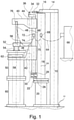
- the remelting plant shown comprises a stationary support column 10 which is rigidly connected at its lower end to a base 12 and extends vertically upwards.
- the support column 10 includes a horizontally disposed cross member 14 which extends across the base of the support column 10 also extends.
- the cross member 14 is rigidly attached to the support column 10 .
- a radial bearing 16 which encloses an upper end of a rotary column 18 , is formed in the cross member 14 at an end remote from the support column 10 .
- the upper end of the rotary column 18 is also referred to here as the second end of the rotary column.
- the rotary column 18 is arranged laterally next to the support column 10 and extends in the vertical direction parallel thereto.
- the rotary column 18 is arranged above a pedestal 20 and is mounted on the lower end (the first end of the rotary column) via an axial bearing 22 so as to be rotatable about an axis of rotation 24 on this pedestal 20 .
- the axis of rotation 24 corresponds here simultaneously to the longitudinal axis of the rotary column 18 and the longitudinal axis of the pedestal 20.
- the pedestal 20 is firmly connected to the base 12.
- a weighing device 26 in the form of a single load cell is attached to the rotary column 18 immediately above the thrust bearing 22 .
- a section of the weighing device 26 spaced apart from the support column 18 in the lateral direction is at least partially surrounded by a ball and socket joint 28 .
- the ball joint 28 is provided at a lower end (a first end) of a guide post 30, thus articulating between the rotary post 18 and the guide post 30.
- An upper end (second end) of the guide post 30 is formed as a free end.
- the guide column 30 can be tilted about the ball joint 28 relative to the rotary column 18 .
- tie bar 30 is shown in an untilted condition in which tie bar 30 extends parallel to pivot post 18 and is laterally spaced therefrom.
- a rotational movement of the rotary column 18 can be transmitted to the guide column 30 by means of the ball joint 28 , so that the guide column 30 can be rotated about the rotary axis 24 together with the rotary column 18 .
- a controllable drive device 32 is provided, which in the exemplary embodiment shown is designed in the form of an XY drive.
- the drive device 32 comprises two drive elements 34, more precisely an X-drive element and a Y-drive element.
- the drive elements 34 can each be moved in a horizontal direction in relation to the drive device 32, with the two directions preferably running perpendicular to one another.
- the drive elements 34 are connected to a head console 36 of the tie column 30 for tilting the tie column 30, while the drive device 32 is connected to the upper end of the rotary column 18.
- the free second end of the guide column 30 can thus be displaced by moving one or both drive elements 34, as a result of which the guide column 30 can be tilted. Since by tilting the guide column 30 not only the lateral distance of the second end of the guide column 30 from the upper end of the rotary column 18 changes, but also the vertical distance between them, the drive device 32 is articulated to the upper end of the rotary column 18 . Further, the drive members 34 are pivotally attached to the head console 36 . The drive device 32 together with the drive elements 34 thus tilts together with the guide column 30 so that a precise tilting of the guide column 30 is ensured in a simple manner by controlling the drive device 32 .
- a tank car 38 and an electrode rod car 40 are guided on the guide column 30 in a displaceable manner.
- the tank car 38 is arranged below the electrode rod car 40, i.e. between the ball joint 28 and the electrode rod car 40.
- the two carriages 38, 40 can be moved axially or along the longitudinal axis of the guide column 30.
- the tank car 38 has a tank car drive device 42 and the electrode rod car 40 has an electrode rod car drive device 44 .
- the carriage drive devices 42, 44 can be controlled separately in order to be able to move the two carriages 38, 40 independently of one another.
- the carriage drive devices 42, 44 are each arranged on or in a recess of the carriage 38, 40 assigned to them.
- the carriage drive devices 42, 44 are designed here as spindle drives, the drive spindle 46 of which is suspended from the head console 36 of the guide column 30 and, starting from this, extends downward parallel to the longitudinal axis of the guide column 30. This enables a particularly space-saving design of the remelting plant.
- an electrode rod 48 is fixedly attached to the electrode rod carriage 40 by means of a screw or clamp connection.
- the electrode rod 48 can therefore be displaced together with the electrode rod carriage 40 by axially displacing it.
- the electrode rod 48 extends vertically downwards from the electrode rod carriage 40 in the direction of a furnace vessel 50 and is thus substantially parallel to the guide column 30.
- the electrode rod 48 is inserted into the furnace vessel 50 via a bushing 52 .
- a bellows 54 is provided between the passage 52 and the furnace vessel 50, through which the electrode rod 48 extends. This bellows 54 ensures that the electrode rod 48 is introduced into the furnace vessel 50 in a vacuum-tight and gas-tight manner.
- the bushing 52 is firmly connected to the tank car 38 via a rigid cross-connection 56 and can be displaced together with it.
- the electrode rod 48 contacts or holds an electrode 58 at its lower end spaced apart from the electrode rod carriage 40, which electrode is melted off in the remelting process.
- the electrode 58 is located in a vacuum and gas-tight furnace chamber formed by the furnace chamber 50 and a crucible 60 of a melting station.
- the electrode 58 can be moved over the electrode rod 48 by means of the electrode rod carriage 40 .
- the consumable electrode 58 can be tracked to achieve a predetermined consumable rate.
- the changing weight of the melting electrode is continuously recorded with the aid of the weighing device 26 and the process is regulated accordingly.
- the furnace boiler 50 can be connected by means of a cardan frame 62 to a contacting section of the tank car 38 that extends in the direction of the furnace boiler 50 .
- the furnace boiler 50 is already positioned or set down on the crucible 60 of the melting station and together with this forms the vacuum-tight and gas-tight furnace boiler room in which the remelting process takes place.
- the contacting section of the tank car 38 is at a predetermined distance below the cardan frame 62, so that there is no direct connection between the tank car 38 and the furnace boiler 50.
- the furnace boiler 50 can be moved vertically by means of the tank car 38. For example, after the end of the remelting process, the furnace boiler 50 can be lifted off the crucible 60 and release it.
- a first high-current cable 64 is connected to a high-current source 66 and fastened to a first cable hanger 68 which is attached to the rotating column 18 for the power supply of the remelting plant.
- a second high current cable 70 is conductively connected to the first high current cable 64 and extends between the first cable hanger 68 on the pivot column 18 and a second cable hanger 72 attached to the guide column 30 .
- a third high current cable 74 is conductively connected to the second high current cable 70 and the electrode rod 48 and extends between the second cable hanger 72 on the guide column 30 and a third cable hanger 76 attached to the electrode rod 48 .
- the electrode 58 is also supplied with high current via the electrode rod 48 .
- the function of the remelting plant is described as follows: Based on the in figure 1 Starting position shown, the remelting process is started and the electrode 58 is continuously melted. For this purpose, the electrode rod carriage 40 with the electrode rod 48 held by it and the electrode 58 is in the highest possible position Starting position in which the electrode rod carriage 40 is arranged below the second free end of the guide column 30. Meanwhile, the furnace kettle 50 is separated from the tank car 38 and placed on the crucible 60 . The consumable electrode 58 is guided into the crucible 60 by controlled displacement of the electrode rod carriage 40 in the direction of the first end of the guide column 30 . For this purpose, the changing weight of the melting electrode is continuously recorded with the aid of the weighing device 26 and the process is regulated accordingly.
- the furnace vessel 50 and electrode bar 48 are to be moved to another melting station.
- a new electrode to be melted is already prepared in the further melting station and protrudes upwards from the crucible of this further melting station.
- the electrode rod carriage 40 with the electrode rod 48 attached to it is moved back up into the starting position by means of the electrode rod carriage drive device 44 .
- the tank car 38 is then moved upwards in the direction of the second free end of the guide column 30 by means of the tank car drive device 42 , as a result of which the contacting section of the tank car 38 is connected to the cardan frame 62 of the furnace boiler 50 .
- the furnace tank 50 is lifted from the crucible 60 of the first melting station.
- the tank car 38 with the furnace chamber 50 connected to it is shifted further axially upwards until a lower end of the furnace chamber 50 viewed in the vertical direction lies above the protruding end of the new electrode to be melted.
- the guide column 30 together with the carriage 38, 40 guided thereon with the electrode rod 48 and furnace vessel 50 is moved from the first melting station to the further melting station by rotating the rotary column 18 about the axis of rotation 24. Because the furnace vessel 50 ends vertically above the prepared electrode, the furnace vessel 50 can be moved over the new electrode without colliding with it. As soon as the electrode rod 48 is located over the new electrode, it can be contacted and clamped by the electrode rod 48 . For this purpose, the electrode rod 48 can optionally be shifted slightly downwards in certain embodiments.
- the tank car 38 is shifted downwards, as a result of which the furnace tank 50 located above the crucible of the further melting station is lowered.
- the new electrode is centered in the crucible of the further melting station by driving the drive device 32 accordingly.
- the drive device 32 tends to center the new electrode, the guide column 30 with the carriages 38, 40 arranged thereon, the carriage drive devices 42, 44 together with the drive spindle 46, the electrode rod 48, the bushing 52 together with the cross connection 56 and the new electrode in the desired directions around the Ball joint 26.
- the furnace vessel 50 remains vertically aligned and is not tilted, since the cardan frame 62 formed between the tank car 38 and the furnace vessel 50 and the bellows 54 formed between the furnace vessel 50 and the bushing 52 essentially compensate for the inclination.
- the furnace vessel 50 is placed on the crucible of the further melting station by axially shifting the tank car 38 in the direction of the first end of the guide column 30, as a result of which the furnace vessel 50 again has a vacuum-tight and gas-tight furnace vessel chamber with the crucible of the further melting station.
- the tank car 38 is then further shifted toward the first end of the guide column 30 by a predetermined distance to disconnect the connection between the contacting portion of the tank car 38 and the gimbal 62 of the furnace tank 50 .
- the weight of the furnace vessel 50 does not act on the weighing device 26 during the subsequent remelting process, since the furnace vessel 50 is only in contact with the weighed components via the bellows 54 .
- the remelting process, including lowering the new electrode, is repeated as described in relation to the first melting station.
Landscapes
- Engineering & Computer Science (AREA)
- Mechanical Engineering (AREA)
- Chemical & Material Sciences (AREA)
- Organic Chemistry (AREA)
- Materials Engineering (AREA)
- Metallurgy (AREA)
- Manufacturing & Machinery (AREA)
- General Engineering & Computer Science (AREA)
- Physics & Mathematics (AREA)
- Plasma & Fusion (AREA)
- Furnace Details (AREA)
- Manufacture And Refinement Of Metals (AREA)
- Waste-Gas Treatment And Other Accessory Devices For Furnaces (AREA)
Priority Applications (1)
| Application Number | Priority Date | Filing Date | Title |
|---|---|---|---|
| SI201930196T SI3752303T1 (sl) | 2018-02-14 | 2019-02-06 | Naprava za pretaljevanje in postopek za obratovanje naprave za pretaljevanje |
Applications Claiming Priority (2)
| Application Number | Priority Date | Filing Date | Title |
|---|---|---|---|
| DE102018103312.5A DE102018103312B4 (de) | 2018-02-14 | 2018-02-14 | Umschmelzanlage und Verfahren zum Betrieb einer Umschmelzanlage |
| PCT/EP2019/052948 WO2019158419A1 (de) | 2018-02-14 | 2019-02-06 | Umschmelzanlage und verfahren zum betrieb einer umschmelzanlage |
Publications (2)
| Publication Number | Publication Date |
|---|---|
| EP3752303A1 EP3752303A1 (de) | 2020-12-23 |
| EP3752303B1 true EP3752303B1 (de) | 2022-01-26 |
Family
ID=65352028
Family Applications (1)
| Application Number | Title | Priority Date | Filing Date |
|---|---|---|---|
| EP19703993.6A Active EP3752303B1 (de) | 2018-02-14 | 2019-02-06 | Umschmelzanlage und verfahren zum betrieb einer umschmelzanlage |
Country Status (7)
| Country | Link |
|---|---|
| US (1) | US11952644B2 (enExample) |
| EP (1) | EP3752303B1 (enExample) |
| JP (1) | JP7268042B2 (enExample) |
| CN (1) | CN111727093B (enExample) |
| DE (1) | DE102018103312B4 (enExample) |
| SI (1) | SI3752303T1 (enExample) |
| WO (1) | WO2019158419A1 (enExample) |
Families Citing this family (1)
| Publication number | Priority date | Publication date | Assignee | Title |
|---|---|---|---|---|
| DE102024134126A1 (de) | 2024-11-20 | 2026-05-21 | Ald Vacuum Technologies Gmbh | Umschmelzanlage |
Family Cites Families (24)
| Publication number | Priority date | Publication date | Assignee | Title |
|---|---|---|---|---|
| US3689680A (en) * | 1971-09-08 | 1972-09-05 | Uwe Reimpel | Electrode melting arrangement |
| AT335090B (de) | 1973-05-30 | 1977-02-25 | Ver Edelstahlwerke Ag | Verfahren zur herstellung von gussblocken mit guter verformbarkeit aus hochschmelzenden eisen- und metallegierungen und vorrichtung zur durchfuhrung dieses verfahrens |
| DE2732873A1 (de) * | 1977-07-21 | 1979-02-15 | Leybold Heraeus Gmbh & Co Kg | Anordnung zur regelung der eintauchtiefe von abschmelzelektroden in elektroschlacke-umschmelzoefen |
| SU794387A1 (ru) | 1979-02-12 | 1981-01-07 | Московский Ордена Ленина Энерге-Тический Институт | Способ определени весаРАСХОдуЕМОгО элЕКТРОдА элЕКТРО-ТЕРМичЕСКОй уСТАНОВКи и уСТРОй-CTBO дл ЕгО ОСущЕСТВлЕНи |
| DE2930354C2 (de) | 1979-07-26 | 1983-11-24 | Special'noe proektno-konstruktorskoe i technologičeskoe bjuro elektrotermičeskogo oborudovanija proizvodstvennogo obiedinenija "Sibelektroterm", Novosibirsk | Elektroschlacke-Umschmelzanlage |
| US4336924A (en) * | 1980-01-21 | 1982-06-29 | Park-Ohio Industries, Inc. | Apparatus for quenching heated workpieces |
| US4280550A (en) * | 1980-02-11 | 1981-07-28 | Consarc Corporation | Electroslag remelting furnace with improved power connection |
| SU932262A1 (ru) | 1980-11-11 | 1982-05-30 | Ордена Трудового Красного Знамени Институт Тепло- И Массообмена Им. А.В.Лыкова | Устройство контрол изменени массы образца |
| AT373177B (de) * | 1982-05-12 | 1983-12-27 | Ver Edelstahlwerke Ag | Einrichtung zur durchfuehrung von umschmelzverfahren mit selbstverzehrenden elektroden |
| DE4204757C2 (de) * | 1992-02-18 | 2001-02-15 | Ald Vacuum Techn Ag | Umschmelzofen |
| DE4207967C2 (de) * | 1992-03-13 | 2001-02-15 | Ald Vacuum Techn Ag | Umschmelzofen |
| JPH07238327A (ja) * | 1994-02-28 | 1995-09-12 | Daido Steel Co Ltd | 真空エレクトロスラグ再溶解炉 |
| DE19921161B4 (de) * | 1999-05-07 | 2011-01-20 | Ald Vacuum Technologies Ag | Elektroschlacke-Umschmelzanlage mit einer Kokille und einer Haube |
| ITBG20080017A1 (it) * | 2008-04-01 | 2009-10-02 | Piccardi S R L | Dispositivo per la regolazione del punto di bloccaggio di un elettrodo |
| DE102012209733A1 (de) | 2012-06-11 | 2013-12-12 | Sgl Carbon Se | Verfahren und Einrichtung zur Bestimmung des Verbrauchs an Elektrodenmaterial beim Betrieb eines Elektroofens |
| DE102013007394A1 (de) * | 2013-04-30 | 2014-10-30 | Ald Vacuum Technologies Gmbh | Umschmelzofen und Kardangelenk insbesondere für die Elektrodenstangenhalterung eines Umschmelzofens |
| CN203683630U (zh) * | 2013-11-28 | 2014-07-02 | 辽宁辽重机械制造有限公司 | 一种百吨级自动化控制大型电渣重熔炉 |
| DE102014014407A1 (de) | 2014-10-02 | 2016-04-07 | Ald Vacuum Technologies Gmbh | Umschmelzofen mit einer Wägezelle |
| CN106288765A (zh) | 2015-05-22 | 2017-01-04 | 江苏国红金属材料有限公司 | 一种熔融金属的电弧炉 |
| CN104846212B (zh) * | 2015-06-08 | 2016-09-21 | 重庆钢铁(集团)有限责任公司 | 一种真空自耗炉冶炼方法 |
| CN205024297U (zh) * | 2015-09-16 | 2016-02-10 | 荣昌县鑫达机械锻造有限公司 | 电渣重熔炉 |
| DE102016100372B4 (de) | 2016-01-11 | 2019-04-04 | Jens Hofmann | Umschmelzanlage |
| ITUB20160079A1 (it) * | 2016-01-19 | 2017-07-19 | Fast Tech S R L | Dispositivo di posizionamento di almeno un elettrodo per forni fusori. |
| CN105671331B (zh) * | 2016-04-12 | 2017-06-20 | 潍坊亚东冶金设备有限公司 | 同轴导电大型板坯电渣炉 |
-
2018
- 2018-02-14 DE DE102018103312.5A patent/DE102018103312B4/de not_active Expired - Fee Related
-
2019
- 2019-02-06 US US16/968,340 patent/US11952644B2/en active Active
- 2019-02-06 JP JP2020543316A patent/JP7268042B2/ja active Active
- 2019-02-06 SI SI201930196T patent/SI3752303T1/sl unknown
- 2019-02-06 EP EP19703993.6A patent/EP3752303B1/de active Active
- 2019-02-06 WO PCT/EP2019/052948 patent/WO2019158419A1/de not_active Ceased
- 2019-02-06 CN CN201980013500.XA patent/CN111727093B/zh active Active
Also Published As
| Publication number | Publication date |
|---|---|
| WO2019158419A1 (de) | 2019-08-22 |
| JP7268042B2 (ja) | 2023-05-02 |
| RU2020127011A (ru) | 2022-02-14 |
| EP3752303A1 (de) | 2020-12-23 |
| JP2021514306A (ja) | 2021-06-10 |
| RU2020127011A3 (enExample) | 2022-02-24 |
| US20200392603A1 (en) | 2020-12-17 |
| CN111727093B (zh) | 2022-04-15 |
| DE102018103312A1 (de) | 2019-08-14 |
| DE102018103312B4 (de) | 2019-08-22 |
| CN111727093A (zh) | 2020-09-29 |
| US11952644B2 (en) | 2024-04-09 |
| SI3752303T1 (sl) | 2022-05-31 |
Similar Documents
| Publication | Publication Date | Title |
|---|---|---|
| DE102009033824B3 (de) | Vorrichtung zum Einspannen eines Werkstücks | |
| EP0291701A1 (de) | Chargiergutvorwärmer zum Vorwärmen von Chargiergut eines metallurgischen Schmelzaggregates | |
| EP0978349B1 (de) | Arbeitsstation | |
| EP2992287B1 (de) | Umschmelzofen und kardangelenk für die elektrodenstangenhalterung eines umschmelzofens | |
| DE2626071C2 (enExample) | ||
| EP1927429A1 (de) | Werkzeugmaschine mit Werkzeugmagazin | |
| EP3075208B1 (de) | Vorrichtung und verfahren zum nachsetzen einer elektrode für einen metallurgischen ofen | |
| EP2846966B1 (de) | Transferzentrum zur spanenden bearbeitung mindestens eines werkstücks, mit einem positionsausgleichssystem | |
| DE102018103312B4 (de) | Umschmelzanlage und Verfahren zum Betrieb einer Umschmelzanlage | |
| DE2412240C2 (de) | Anhebevorrichtung für die obere Gießband-Tragvorrichtung einer Stranggießmaschine | |
| DE3626888C2 (enExample) | ||
| DE102010041692A1 (de) | Hub- und Schwenkvorrichtung für einen Deckel eines Ofens sowie Ofenanlage und Verfahren zum Chargieren und zur Wartung einer solchen Ofenanlage | |
| EP3581664B2 (de) | Vorrichtung, umfassend ein metallurgisches gefäss | |
| EP2952268A1 (de) | Biegemaschine | |
| DE2833695A1 (de) | Elektroschlackeumschmelzanlage mit koaxialen strompfaden | |
| DE102017108069A1 (de) | Hebebühne | |
| DE3047214A1 (de) | Elektroschlackeumschmelzofen fuer abschmelzelektroden mit einem elektrodenantrieb | |
| DE3410656A1 (de) | Werkzeugmaschine mit einem in mehreren achsen beweglichen spindelstock | |
| EP4321273A1 (de) | Werkstückmanipulator | |
| DE2819836A1 (de) | Lichtbogenofen | |
| DE2905752C2 (de) | Elektroden-Einspannvorrichtung für Elektroumschmelzanlagen | |
| DE102024134126A1 (de) | Umschmelzanlage | |
| DE102024118760B3 (de) | Schmiedepresse, Schmiedevorrichtung und Verfahren zum Schmieden | |
| WO1997005438A2 (de) | Lichtbogenofen insbesondere gleichstromlichtbogenofen und verfahren zur vermeidung von überhitzungen der ofenwand | |
| DE102024110702A1 (de) | Automatisiertes Handhabungssystem und Verfahren zum Betreiben eines automatisierten Handhabungssystems |
Legal Events
| Date | Code | Title | Description |
|---|---|---|---|
| STAA | Information on the status of an ep patent application or granted ep patent |
Free format text: STATUS: UNKNOWN |
|
| STAA | Information on the status of an ep patent application or granted ep patent |
Free format text: STATUS: THE INTERNATIONAL PUBLICATION HAS BEEN MADE |
|
| PUAI | Public reference made under article 153(3) epc to a published international application that has entered the european phase |
Free format text: ORIGINAL CODE: 0009012 |
|
| STAA | Information on the status of an ep patent application or granted ep patent |
Free format text: STATUS: REQUEST FOR EXAMINATION WAS MADE |
|
| 17P | Request for examination filed |
Effective date: 20200821 |
|
| AK | Designated contracting states |
Kind code of ref document: A1 Designated state(s): AL AT BE BG CH CY CZ DE DK EE ES FI FR GB GR HR HU IE IS IT LI LT LU LV MC MK MT NL NO PL PT RO RS SE SI SK SM TR |
|
| AX | Request for extension of the european patent |
Extension state: BA ME |
|
| DAV | Request for validation of the european patent (deleted) | ||
| DAX | Request for extension of the european patent (deleted) | ||
| GRAP | Despatch of communication of intention to grant a patent |
Free format text: ORIGINAL CODE: EPIDOSNIGR1 |
|
| STAA | Information on the status of an ep patent application or granted ep patent |
Free format text: STATUS: GRANT OF PATENT IS INTENDED |
|
| RIC1 | Information provided on ipc code assigned before grant |
Ipc: H05B 7/10 20060101ALI20210927BHEP Ipc: F27D 11/10 20060101ALI20210927BHEP Ipc: C22B 9/18 20060101ALI20210927BHEP Ipc: B22D 23/10 20060101AFI20210927BHEP |
|
| INTG | Intention to grant announced |
Effective date: 20211020 |
|
| GRAS | Grant fee paid |
Free format text: ORIGINAL CODE: EPIDOSNIGR3 |
|
| GRAA | (expected) grant |
Free format text: ORIGINAL CODE: 0009210 |
|
| STAA | Information on the status of an ep patent application or granted ep patent |
Free format text: STATUS: THE PATENT HAS BEEN GRANTED |
|
| AK | Designated contracting states |
Kind code of ref document: B1 Designated state(s): AL AT BE BG CH CY CZ DE DK EE ES FI FR GB GR HR HU IE IS IT LI LT LU LV MC MK MT NL NO PL PT RO RS SE SI SK SM TR |
|
| REG | Reference to a national code |
Ref country code: GB Ref legal event code: FG4D Free format text: NOT ENGLISH |
|
| REG | Reference to a national code |
Ref country code: CH Ref legal event code: EP |
|
| REG | Reference to a national code |
Ref country code: AT Ref legal event code: REF Ref document number: 1464858 Country of ref document: AT Kind code of ref document: T Effective date: 20220215 |
|
| REG | Reference to a national code |
Ref country code: IE Ref legal event code: FG4D Free format text: LANGUAGE OF EP DOCUMENT: GERMAN |
|
| REG | Reference to a national code |
Ref country code: DE Ref legal event code: R096 Ref document number: 502019003325 Country of ref document: DE |
|
| REG | Reference to a national code |
Ref country code: LT Ref legal event code: MG9D |
|
| REG | Reference to a national code |
Ref country code: NL Ref legal event code: MP Effective date: 20220126 |
|
| PG25 | Lapsed in a contracting state [announced via postgrant information from national office to epo] |
Ref country code: NL Free format text: LAPSE BECAUSE OF FAILURE TO SUBMIT A TRANSLATION OF THE DESCRIPTION OR TO PAY THE FEE WITHIN THE PRESCRIBED TIME-LIMIT Effective date: 20220126 |
|
| PG25 | Lapsed in a contracting state [announced via postgrant information from national office to epo] |
Ref country code: SE Free format text: LAPSE BECAUSE OF FAILURE TO SUBMIT A TRANSLATION OF THE DESCRIPTION OR TO PAY THE FEE WITHIN THE PRESCRIBED TIME-LIMIT Effective date: 20220126 Ref country code: RS Free format text: LAPSE BECAUSE OF FAILURE TO SUBMIT A TRANSLATION OF THE DESCRIPTION OR TO PAY THE FEE WITHIN THE PRESCRIBED TIME-LIMIT Effective date: 20220126 Ref country code: PT Free format text: LAPSE BECAUSE OF FAILURE TO SUBMIT A TRANSLATION OF THE DESCRIPTION OR TO PAY THE FEE WITHIN THE PRESCRIBED TIME-LIMIT Effective date: 20220526 Ref country code: NO Free format text: LAPSE BECAUSE OF FAILURE TO SUBMIT A TRANSLATION OF THE DESCRIPTION OR TO PAY THE FEE WITHIN THE PRESCRIBED TIME-LIMIT Effective date: 20220426 Ref country code: LT Free format text: LAPSE BECAUSE OF FAILURE TO SUBMIT A TRANSLATION OF THE DESCRIPTION OR TO PAY THE FEE WITHIN THE PRESCRIBED TIME-LIMIT Effective date: 20220126 Ref country code: HR Free format text: LAPSE BECAUSE OF FAILURE TO SUBMIT A TRANSLATION OF THE DESCRIPTION OR TO PAY THE FEE WITHIN THE PRESCRIBED TIME-LIMIT Effective date: 20220126 Ref country code: ES Free format text: LAPSE BECAUSE OF FAILURE TO SUBMIT A TRANSLATION OF THE DESCRIPTION OR TO PAY THE FEE WITHIN THE PRESCRIBED TIME-LIMIT Effective date: 20220126 Ref country code: BG Free format text: LAPSE BECAUSE OF FAILURE TO SUBMIT A TRANSLATION OF THE DESCRIPTION OR TO PAY THE FEE WITHIN THE PRESCRIBED TIME-LIMIT Effective date: 20220426 |
|
| PG25 | Lapsed in a contracting state [announced via postgrant information from national office to epo] |
Ref country code: PL Free format text: LAPSE BECAUSE OF FAILURE TO SUBMIT A TRANSLATION OF THE DESCRIPTION OR TO PAY THE FEE WITHIN THE PRESCRIBED TIME-LIMIT Effective date: 20220126 Ref country code: LV Free format text: LAPSE BECAUSE OF FAILURE TO SUBMIT A TRANSLATION OF THE DESCRIPTION OR TO PAY THE FEE WITHIN THE PRESCRIBED TIME-LIMIT Effective date: 20220126 Ref country code: GR Free format text: LAPSE BECAUSE OF FAILURE TO SUBMIT A TRANSLATION OF THE DESCRIPTION OR TO PAY THE FEE WITHIN THE PRESCRIBED TIME-LIMIT Effective date: 20220427 Ref country code: FI Free format text: LAPSE BECAUSE OF FAILURE TO SUBMIT A TRANSLATION OF THE DESCRIPTION OR TO PAY THE FEE WITHIN THE PRESCRIBED TIME-LIMIT Effective date: 20220126 |
|
| PG25 | Lapsed in a contracting state [announced via postgrant information from national office to epo] |
Ref country code: IS Free format text: LAPSE BECAUSE OF FAILURE TO SUBMIT A TRANSLATION OF THE DESCRIPTION OR TO PAY THE FEE WITHIN THE PRESCRIBED TIME-LIMIT Effective date: 20220526 |
|
| REG | Reference to a national code |
Ref country code: CH Ref legal event code: PL |
|
| REG | Reference to a national code |
Ref country code: BE Ref legal event code: MM Effective date: 20220228 |
|
| REG | Reference to a national code |
Ref country code: DE Ref legal event code: R097 Ref document number: 502019003325 Country of ref document: DE |
|
| PG25 | Lapsed in a contracting state [announced via postgrant information from national office to epo] |
Ref country code: SM Free format text: LAPSE BECAUSE OF FAILURE TO SUBMIT A TRANSLATION OF THE DESCRIPTION OR TO PAY THE FEE WITHIN THE PRESCRIBED TIME-LIMIT Effective date: 20220126 Ref country code: SK Free format text: LAPSE BECAUSE OF FAILURE TO SUBMIT A TRANSLATION OF THE DESCRIPTION OR TO PAY THE FEE WITHIN THE PRESCRIBED TIME-LIMIT Effective date: 20220126 Ref country code: RO Free format text: LAPSE BECAUSE OF FAILURE TO SUBMIT A TRANSLATION OF THE DESCRIPTION OR TO PAY THE FEE WITHIN THE PRESCRIBED TIME-LIMIT Effective date: 20220126 Ref country code: MC Free format text: LAPSE BECAUSE OF FAILURE TO SUBMIT A TRANSLATION OF THE DESCRIPTION OR TO PAY THE FEE WITHIN THE PRESCRIBED TIME-LIMIT Effective date: 20220126 Ref country code: LU Free format text: LAPSE BECAUSE OF NON-PAYMENT OF DUE FEES Effective date: 20220206 Ref country code: EE Free format text: LAPSE BECAUSE OF FAILURE TO SUBMIT A TRANSLATION OF THE DESCRIPTION OR TO PAY THE FEE WITHIN THE PRESCRIBED TIME-LIMIT Effective date: 20220126 Ref country code: DK Free format text: LAPSE BECAUSE OF FAILURE TO SUBMIT A TRANSLATION OF THE DESCRIPTION OR TO PAY THE FEE WITHIN THE PRESCRIBED TIME-LIMIT Effective date: 20220126 Ref country code: CZ Free format text: LAPSE BECAUSE OF FAILURE TO SUBMIT A TRANSLATION OF THE DESCRIPTION OR TO PAY THE FEE WITHIN THE PRESCRIBED TIME-LIMIT Effective date: 20220126 |
|
| PG25 | Lapsed in a contracting state [announced via postgrant information from national office to epo] |
Ref country code: AL Free format text: LAPSE BECAUSE OF FAILURE TO SUBMIT A TRANSLATION OF THE DESCRIPTION OR TO PAY THE FEE WITHIN THE PRESCRIBED TIME-LIMIT Effective date: 20220126 |
|
| PLBE | No opposition filed within time limit |
Free format text: ORIGINAL CODE: 0009261 |
|
| STAA | Information on the status of an ep patent application or granted ep patent |
Free format text: STATUS: NO OPPOSITION FILED WITHIN TIME LIMIT |
|
| 26N | No opposition filed |
Effective date: 20221027 |
|
| PG25 | Lapsed in a contracting state [announced via postgrant information from national office to epo] |
Ref country code: LI Free format text: LAPSE BECAUSE OF NON-PAYMENT OF DUE FEES Effective date: 20220228 Ref country code: IE Free format text: LAPSE BECAUSE OF NON-PAYMENT OF DUE FEES Effective date: 20220206 Ref country code: CH Free format text: LAPSE BECAUSE OF NON-PAYMENT OF DUE FEES Effective date: 20220228 |
|
| PG25 | Lapsed in a contracting state [announced via postgrant information from national office to epo] |
Ref country code: BE Free format text: LAPSE BECAUSE OF NON-PAYMENT OF DUE FEES Effective date: 20220228 |
|
| P01 | Opt-out of the competence of the unified patent court (upc) registered |
Effective date: 20230524 |
|
| PG25 | Lapsed in a contracting state [announced via postgrant information from national office to epo] |
Ref country code: MK Free format text: LAPSE BECAUSE OF FAILURE TO SUBMIT A TRANSLATION OF THE DESCRIPTION OR TO PAY THE FEE WITHIN THE PRESCRIBED TIME-LIMIT Effective date: 20220126 Ref country code: CY Free format text: LAPSE BECAUSE OF FAILURE TO SUBMIT A TRANSLATION OF THE DESCRIPTION OR TO PAY THE FEE WITHIN THE PRESCRIBED TIME-LIMIT Effective date: 20220126 |
|
| PG25 | Lapsed in a contracting state [announced via postgrant information from national office to epo] |
Ref country code: HU Free format text: LAPSE BECAUSE OF FAILURE TO SUBMIT A TRANSLATION OF THE DESCRIPTION OR TO PAY THE FEE WITHIN THE PRESCRIBED TIME-LIMIT; INVALID AB INITIO Effective date: 20190206 |
|
| PG25 | Lapsed in a contracting state [announced via postgrant information from national office to epo] |
Ref country code: MT Free format text: LAPSE BECAUSE OF FAILURE TO SUBMIT A TRANSLATION OF THE DESCRIPTION OR TO PAY THE FEE WITHIN THE PRESCRIBED TIME-LIMIT Effective date: 20220126 |
|
| PG25 | Lapsed in a contracting state [announced via postgrant information from national office to epo] |
Ref country code: TR Free format text: LAPSE BECAUSE OF FAILURE TO SUBMIT A TRANSLATION OF THE DESCRIPTION OR TO PAY THE FEE WITHIN THE PRESCRIBED TIME-LIMIT Effective date: 20220126 |
|
| PGFP | Annual fee paid to national office [announced via postgrant information from national office to epo] |
Ref country code: GB Payment date: 20260219 Year of fee payment: 8 |
|
| PGFP | Annual fee paid to national office [announced via postgrant information from national office to epo] |
Ref country code: DE Payment date: 20260217 Year of fee payment: 8 |
|
| PGFP | Annual fee paid to national office [announced via postgrant information from national office to epo] |
Ref country code: AT Payment date: 20260216 Year of fee payment: 8 |
|
| PGFP | Annual fee paid to national office [announced via postgrant information from national office to epo] |
Ref country code: IT Payment date: 20260227 Year of fee payment: 8 |
|
| PGFP | Annual fee paid to national office [announced via postgrant information from national office to epo] |
Ref country code: FR Payment date: 20260219 Year of fee payment: 8 |
|
| PGFP | Annual fee paid to national office [announced via postgrant information from national office to epo] |
Ref country code: SI Payment date: 20260126 Year of fee payment: 8 |