EP3751297B1 - Sicherheitsschaltereingangsdiagnosevorrichtung und arbeitsmaschine damit - Google Patents
Sicherheitsschaltereingangsdiagnosevorrichtung und arbeitsmaschine damit Download PDFInfo
- Publication number
- EP3751297B1 EP3751297B1 EP19866992.1A EP19866992A EP3751297B1 EP 3751297 B1 EP3751297 B1 EP 3751297B1 EP 19866992 A EP19866992 A EP 19866992A EP 3751297 B1 EP3751297 B1 EP 3751297B1
- Authority
- EP
- European Patent Office
- Prior art keywords
- circuit
- switch
- controller
- resistor
- diagnosis
- Prior art date
- Legal status (The legal status is an assumption and is not a legal conclusion. Google has not performed a legal analysis and makes no representation as to the accuracy of the status listed.)
- Active
Links
Images




Classifications
-
- H—ELECTRICITY
- H01—ELECTRIC ELEMENTS
- H01H—ELECTRIC SWITCHES; RELAYS; SELECTORS; EMERGENCY PROTECTIVE DEVICES
- H01H3/00—Mechanisms for operating contacts
- H01H3/02—Operating parts, i.e. for operating driving mechanism by a mechanical force external to the switch
- H01H3/022—Emergency operating parts, e.g. for stop-switch in dangerous conditions
-
- B—PERFORMING OPERATIONS; TRANSPORTING
- B60—VEHICLES IN GENERAL
- B60L—PROPULSION OF ELECTRICALLY-PROPELLED VEHICLES; SUPPLYING ELECTRIC POWER FOR AUXILIARY EQUIPMENT OF ELECTRICALLY-PROPELLED VEHICLES; ELECTRODYNAMIC BRAKE SYSTEMS FOR VEHICLES IN GENERAL; MAGNETIC SUSPENSION OR LEVITATION FOR VEHICLES; MONITORING OPERATING VARIABLES OF ELECTRICALLY-PROPELLED VEHICLES; ELECTRIC SAFETY DEVICES FOR ELECTRICALLY-PROPELLED VEHICLES
- B60L3/00—Electric devices on electrically-propelled vehicles for safety purposes; Monitoring operating variables, e.g. speed, deceleration or energy consumption
- B60L3/04—Cutting off the power supply under fault conditions
-
- B—PERFORMING OPERATIONS; TRANSPORTING
- B60—VEHICLES IN GENERAL
- B60L—PROPULSION OF ELECTRICALLY-PROPELLED VEHICLES; SUPPLYING ELECTRIC POWER FOR AUXILIARY EQUIPMENT OF ELECTRICALLY-PROPELLED VEHICLES; ELECTRODYNAMIC BRAKE SYSTEMS FOR VEHICLES IN GENERAL; MAGNETIC SUSPENSION OR LEVITATION FOR VEHICLES; MONITORING OPERATING VARIABLES OF ELECTRICALLY-PROPELLED VEHICLES; ELECTRIC SAFETY DEVICES FOR ELECTRICALLY-PROPELLED VEHICLES
- B60L3/00—Electric devices on electrically-propelled vehicles for safety purposes; Monitoring operating variables, e.g. speed, deceleration or energy consumption
- B60L3/0023—Detecting, eliminating, remedying or compensating for drive train abnormalities, e.g. failures within the drive train
- B60L3/0084—Detecting, eliminating, remedying or compensating for drive train abnormalities, e.g. failures within the drive train relating to control modules
-
- B—PERFORMING OPERATIONS; TRANSPORTING
- B60—VEHICLES IN GENERAL
- B60L—PROPULSION OF ELECTRICALLY-PROPELLED VEHICLES; SUPPLYING ELECTRIC POWER FOR AUXILIARY EQUIPMENT OF ELECTRICALLY-PROPELLED VEHICLES; ELECTRODYNAMIC BRAKE SYSTEMS FOR VEHICLES IN GENERAL; MAGNETIC SUSPENSION OR LEVITATION FOR VEHICLES; MONITORING OPERATING VARIABLES OF ELECTRICALLY-PROPELLED VEHICLES; ELECTRIC SAFETY DEVICES FOR ELECTRICALLY-PROPELLED VEHICLES
- B60L50/00—Electric propulsion with power supplied within the vehicle
- B60L50/10—Electric propulsion with power supplied within the vehicle using propulsion power supplied by engine-driven generators, e.g. generators driven by combustion engines
-
- B—PERFORMING OPERATIONS; TRANSPORTING
- B60—VEHICLES IN GENERAL
- B60W—CONJOINT CONTROL OF VEHICLE SUB-UNITS OF DIFFERENT TYPE OR DIFFERENT FUNCTION; CONTROL SYSTEMS SPECIALLY ADAPTED FOR HYBRID VEHICLES; ROAD VEHICLE DRIVE CONTROL SYSTEMS FOR PURPOSES NOT RELATED TO THE CONTROL OF A PARTICULAR SUB-UNIT
- B60W50/00—Details of control systems for road vehicle drive control not related to the control of a particular sub-unit, e.g. process diagnostic or vehicle driver interfaces
- B60W50/0098—Details of control systems ensuring comfort, safety or stability not otherwise provided for
-
- G—PHYSICS
- G01—MEASURING; TESTING
- G01R—MEASURING ELECTRIC VARIABLES; MEASURING MAGNETIC VARIABLES
- G01R31/00—Arrangements for testing electric properties; Arrangements for locating electric faults; Arrangements for electrical testing characterised by what is being tested not provided for elsewhere
- G01R31/327—Testing of circuit interrupters, switches or circuit-breakers
- G01R31/3277—Testing of circuit interrupters, switches or circuit-breakers of low voltage devices, e.g. domestic or industrial devices, such as motor protections, relays, rotation switches
-
- H—ELECTRICITY
- H01—ELECTRIC ELEMENTS
- H01H—ELECTRIC SWITCHES; RELAYS; SELECTORS; EMERGENCY PROTECTIVE DEVICES
- H01H83/00—Protective switches, e.g. circuit-breaking switches, or protective relays operated by abnormal electrical conditions otherwise than solely by excess current
- H01H83/16—Protective switches, e.g. circuit-breaking switches, or protective relays operated by abnormal electrical conditions otherwise than solely by excess current operated by abnormal ratio of voltage and current, e.g. distance relay
-
- H—ELECTRICITY
- H02—GENERATION; CONVERSION OR DISTRIBUTION OF ELECTRIC POWER
- H02H—EMERGENCY PROTECTIVE CIRCUIT ARRANGEMENTS
- H02H1/00—Details of emergency protective circuit arrangements
- H02H1/0061—Details of emergency protective circuit arrangements concerning transmission of signals
-
- H—ELECTRICITY
- H02—GENERATION; CONVERSION OR DISTRIBUTION OF ELECTRIC POWER
- H02H—EMERGENCY PROTECTIVE CIRCUIT ARRANGEMENTS
- H02H3/00—Emergency protective circuit arrangements for automatic disconnection directly responsive to an undesired change from normal electric working condition with or without subsequent reconnection ; integrated protection
- H02H3/02—Details
- H02H3/04—Details with warning or supervision in addition to disconnection, e.g. for indicating that protective apparatus has functioned
- H02H3/042—Details with warning or supervision in addition to disconnection, e.g. for indicating that protective apparatus has functioned combined with means for locating the fault
-
- B—PERFORMING OPERATIONS; TRANSPORTING
- B60—VEHICLES IN GENERAL
- B60L—PROPULSION OF ELECTRICALLY-PROPELLED VEHICLES; SUPPLYING ELECTRIC POWER FOR AUXILIARY EQUIPMENT OF ELECTRICALLY-PROPELLED VEHICLES; ELECTRODYNAMIC BRAKE SYSTEMS FOR VEHICLES IN GENERAL; MAGNETIC SUSPENSION OR LEVITATION FOR VEHICLES; MONITORING OPERATING VARIABLES OF ELECTRICALLY-PROPELLED VEHICLES; ELECTRIC SAFETY DEVICES FOR ELECTRICALLY-PROPELLED VEHICLES
- B60L2200/00—Type of vehicles
- B60L2200/40—Working vehicles
-
- G—PHYSICS
- G01—MEASURING; TESTING
- G01R—MEASURING ELECTRIC VARIABLES; MEASURING MAGNETIC VARIABLES
- G01R31/00—Arrangements for testing electric properties; Arrangements for locating electric faults; Arrangements for electrical testing characterised by what is being tested not provided for elsewhere
- G01R31/327—Testing of circuit interrupters, switches or circuit-breakers
-
- G—PHYSICS
- G01—MEASURING; TESTING
- G01R—MEASURING ELECTRIC VARIABLES; MEASURING MAGNETIC VARIABLES
- G01R31/00—Arrangements for testing electric properties; Arrangements for locating electric faults; Arrangements for electrical testing characterised by what is being tested not provided for elsewhere
- G01R31/50—Testing of electric apparatus, lines, cables or components for short-circuits, continuity, leakage current or incorrect line connections
- G01R31/58—Testing of lines, cables or conductors
-
- Y—GENERAL TAGGING OF NEW TECHNOLOGICAL DEVELOPMENTS; GENERAL TAGGING OF CROSS-SECTIONAL TECHNOLOGIES SPANNING OVER SEVERAL SECTIONS OF THE IPC; TECHNICAL SUBJECTS COVERED BY FORMER USPC CROSS-REFERENCE ART COLLECTIONS [XRACs] AND DIGESTS
- Y02—TECHNOLOGIES OR APPLICATIONS FOR MITIGATION OR ADAPTATION AGAINST CLIMATE CHANGE
- Y02T—CLIMATE CHANGE MITIGATION TECHNOLOGIES RELATED TO TRANSPORTATION
- Y02T10/00—Road transport of goods or passengers
- Y02T10/60—Other road transportation technologies with climate change mitigation effect
- Y02T10/7072—Electromobility specific charging systems or methods for batteries, ultracapacitors, supercapacitors or double-layer capacitors
Definitions
- the present invention relates to a safety switch input diagnosis device and a work machine using the safety switch input diagnosis device.
- Patent Document 1 discloses a wiring method for a robot for causing a plurality of robot controllers to perform emergency stop action by an operation of a single operation switch.
- the wiring method is performed by a robot system configured from a single master controller that includes a first safety monitoring section that performs emergency stop action on the basis of whether or not a safety input signal via the operation switch is inputted and a second safety monitoring section that performs emergency stop action on the basis of whether or not a safety input signal via the operation switch is inputted and outputs a permission signal, and equal to or more than slave controllers each including the first safety monitoring sectionand emergency stopping means that acts in response to the permission signal.
- the master controller wires an input path for a safety input signal via the operation switch and an output path for the permission signal outputted from the second safety monitoring section of the master controller in such a manner as to allow outputting to the outside, connects the operation switch and the master controller to each other by a first connection cable, and connects the master controller and the slave controller to each other by a second connection table.
- the slave controller connects the first safety monitoring section to the input path for the safety input signal and connects the emergency stop means to the output path or the permission signal.
- Patent Document 1 JP-2016-124077-A JP 2011 247843 A discloses an abnormality detection circuit with a machine part and a circuit board, the circuit board having a switch with a parallel and a series resistor and taps towards the machine part.
- a failure of a circuit including an operation switch is diagnosed by monitoring whether or not a potential state occurring when a test pulse is inputted to the circuit.
- an open state by an operation of the operation switch and a disconnection state of a line cannot be distinguished from each other, and the countermeasure related to functional safety is not sufficient.
- a safety switch input diagnosis device has the features of claim 1. It includes a first circuit formed from a series connection of a switch capable of interrupting connection between a first contact and a second contact and a line having a first resistor connected to the first or the second contact of the switch, a second circuit having a second resistor between one end and another end and connected at the one end to one end of the first circuit, a third circuit connected at one end to the other end of the second circuit and at another end to a power supply, a fourth circuit connected at one end to another end of the first circuit, a fifth circuit having a third resistor between one end and another end and connected at the one end to another end of the fourth circuit and at the other end to a ground, a sixth circuit having a fourth resistor between one end and another end and connected at the one end to the one end of the first circuit and at the other end to the other end of the first circuit, a seventh circuit connected at one end to the one end of the first circuit, an eighth circuit having a fifth resistor between one end and another end and connected
- an operation of the switch and a failure mode of the circuit related to the switch can be diagnosed.
- a first embodiment is described with reference to FIGS. 1 to 5 and 10 .
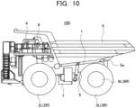
- FIG. 10 is a side elevational view schematically depicting an appearance of a dump truck according to the present embodiment.
- FIG. 10 in regard to a driven wheel, a driving wheel, a travelling motor, and so forth, only one of paired left and right configurations is depicted and denoted by a reference character while the other is not depicted but is denoted only by a reference character in parentheses in the figure.
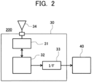
- FIGS. 1 and 2 are views depicting a safety switch input diagnosis system according to the present embodiment, and FIG. 1 depicts a transmission system including an emergency stop switch and a safety switch input diagnosis device and FIG.2 depicts a reception system that receives the emergency stop signal transmitted from the transmission system and outputs the emergence stop signal to a machine body controller.
- the dump truck 100 of the electrically driven type is generally configured from a machine body frame 1 that extends in the forward and rearward direction and forms a supporting structure, a loading platform (vessel) 5 arranged so as to extend in the forward and rearward direction at an upper portion of the machine body frame 1 and provided for tilting movement on the machine body frame 1 through a pin coupling portion 5a at a rear end lower portion thereof, a pair of driven wheels (front wheels) 2L and 2R provided on the left and right of a front side under the machine body frame 1, a pair of driving wheels (rear wheels) 3L and 3R provided on the left and right of a rear side under the machine body, a cabin 4 provided on the front side over the machine body frame 1, a fuel tank 7 provided under the machine body frame 1, an engine (not depicted) arranged on the machine body frame 1 and driven by fuel supplied from the fuel tank 7, a generator (not depicted) connected to and driven by the engine, and travelling motors 9L and 9R that drive the wheels (
- the travelling motors 9L and 9R are accommodated in a rotary shaft portion of the driving wheels 3L and 3R together with a speed reducer not depicted.
- the machine body frame 1 and the loading platform 5 are connected to each other by a hoist cylinder 6, and the loading platform 5 is pivoted around the pin coupling portion 5a by extension/contraction of the hoist cylinder 6.
- a deck on which an operator can walk is attached to the machine body frame 1, and the operator can move to the cabin 4 through the deck.
- an accelerator pedal, a brake pedal, a hoist pedal, a steering member, and so forth are installed in the inside of the cabin 4.
- the operator will control the accelerating force or the braking force of the dump truck 100 in accordance with an operation amount of the accelerator pedal or the brake pedal in the cabin 4, turn the steering member to the left or the right to perform a steering operation by hydraulic driving, and operate the hoist pedal to perform dumping operation of the loading platform 5 by hydraulic driving.
- a control cabinet 8 in which various power equipment is accommodated is carried.
- a machine body controller 40 for controlling action of the entire dump truck 100 is installed.
- the machine body controller 40 controls action of the dump truck 100 on the basis of an operation instruction inputted from the accelerator pedal, brake pedal, hoist pedal, steering wheel or the like.
- the machine body controller 40 further performs emergency stop control for stopping at least track action of the dump truck 100 on the basis of an emergency stop signal outputted by an operation of an emergency stop switch 14 of a safety switch input diagnosis system 200.
- a main pump and so forth that is a hydraulic fluid source for the hydraulic equipment are carried in addition to the engine and the generator.
- the safety switch input diagnosis system 200 is configured from a transmission system (refer to FIG. 1 ) including the emergency stop switch and the safety switch input diagnosis device and a reception system (refer to FIG. 2 ) that receives and outputs an emergency stop signal transmitted from the transmission signal to the machine body controller.
- the safety switch input diagnosis system 200 includes a circuit 12 (first circuit) formed by a serial connection of the emergency stop switch 14 in which connection between a first contact 14a and a second contact 14b is interrupted by a pushing-in operation and a line having a resistor (first resistor) of a resistance value R2 connected to the first contact 14a or second contact 14b of the emergency stop switch 14, a circuit 11 (second circuit) having a resistor (second resistor) of a resistance value R1 between one end and the other end and connected at the one end to one end of the circuit 12, a line L1 (third circuit) connected at one end to the other end of the circuit 11 and connected at the other end to a power supply (Vcc) of a transmission unit 20, a line L3 (fourth circuit) connected at one end to the other end of the circuit 12, a circuit 22 (fifth circuit) having a resistor (third resistor) of a resistance value R5 between one end and the other end and connected at the one end to the other end of the line L3 and at
- FIG. 1 depicts such that the resistor of the resistance value R2 is provided on the power supply (Vcc) side of the emergency stop switch 14, it is sufficient if the resistor of the resistance value R2 is provided as the circuit 12 including the emergency stop switch 14, and accordingly, it is similar even if it is expressed that the resistor of the resistance value R2 is provided on the ground (GND) side of the emergency stop switch 14.
- the transmission system of the safety switch input diagnosis system 200 is generally configured from a switch unit 10 including the emergency stop switch 14, the transmission unit 20 that transmits an emergency stop signal to the reception system, and the plurality of lines L1 to L3 that configure a signal cable for connecting the switch unit 10 and the transmission unit 20.
- the switch unit 10 is configured including the emergency stop switch 14 for the instruction of emergency stop by an operation of the operator, and the circuits 11 to 13.
- the circuit 11 is connected at the other end to a connector 10a for the connection to the outside of the switch unit 10.
- the circuit 12 is connected at the one end (one end of the circuit 13) to a connector 10b for the connection to the outside of the switch unit 10, and the circuit 12 is connected at the other end (another end of the circuit 13) to a connector 10c.
- the emergency stop switch 14 is configured such that, for example, a button (power point) for being operated by the operator and a conductor (action point) that establishes conduction between the first and second contacts 14a and 14b are configured integrally as a rigid body and the contacts are released (interrupted) by an operation of the operator, and conforms to international standards formulated by so-called IEC (International Electrotechnical Commission), ISO (International Organization for Standardization), or the like.
- IEC International Electrotechnical Commission
- ISO International Organization for Standardization
- the transmission unit 20 is configured including a power supply (Vcc) and the ground (GND), the circuits 21 and 22, the controller 23 that diagnoses a connection state of the emergency stop switch 14 and a failure mode of the lines L1 to L3 and outputs results of the diagnosis, a transmission device that transmits an emergency stop signal that is one of the results of the diagnosis of the controller 23 via an antenna 25, and a notification device 26 that notifies the operator of the information of a failure mode that is one of the results of the diagnosis of the controller 23.
- the power supply is connected to a connector 20a for the connection to the outside of the transmission unit 20.
- the circuit 21 is connected at the one end to a connector 20b for the connection to the outside of the transmission unit 20, and the circuit 22 is connected at the one end to a connector 20c.
- a voltage value VREF(H) of the power supply (Vcc), a voltage value VREF(L) of the ground (GND) and a voltage value (ADIN(1)) at the one end of the circuit 21 are inputted.
- the controller 23 diagnoses a connection state of the emergency stop switch 14 and a failure mode of the lines L1 to L3 on the basis of the voltage values VREF(H), VREF(L), and ADIN(1).
- the diagnosis process of the controller 23 is hereinafter described in detail.
- the notification device 26 notifies the operator of a diagnosis result of a failure mode to encourage the operator to respond and includes, for example, a monitor or a buzzer.
- the connectors 10a to 10c of the switch unit 10 and the connectors 20a to 20c of the transmission unit 20 are connected by the lines L1 to L3 configuring a signal cable, respectively.
- the reception system of the safety switch input diagnosis system 200 is arranged on the control cabinet 8 or the like of the dump truck 100 and is configured from a reception unit 30 including a reception device 31 that receives a result of a diagnosis (emergency stop signal) transmitted from the transmission unit 20 of the transmission system through an antenna 34 and a reception controller 32 that outputs the emergency stop signal received by the reception device 31 to the machine body controller 40 of the dump truck 100 through an interface 33.
- a reception unit 30 including a reception device 31 that receives a result of a diagnosis (emergency stop signal) transmitted from the transmission unit 20 of the transmission system through an antenna 34 and a reception controller 32 that outputs the emergency stop signal received by the reception device 31 to the machine body controller 40 of the dump truck 100 through an interface 33.
- the transmission system of the safety switch input diagnosis system 200 is arranged in a monitor room or the like while the reception system is arranged on the dump truck 100.
- an emergency stop signal is transmitted from the transmission unit 20 to the reception unit 30 to stop action of the dump truck 100.
- FIG. 3 is a view depicting values of voltage values inputted to the controller in regarding with each of the connection state of the emergency stop switch and the failure modes.
- a voltage value ADIN(1) to be inputted to the controller 23 is found in each of the cases of the connection state of the emergency stop switch and the failure modes as depicted in FIG. 3 .
- the resistance values R1 to R3, R4, and R5 of the circuits 11 to 13, 21, and 22 in the present embodiment are set such that, in the cases of each of the connection state of the emergency stop switch and the failure modes, the voltage value ADIN(1) indicates values different from one another.
- the controller 23 can uniquely diagnose the connection state of the emergency stop switch and the failure modes on the basis of the voltage value ADIN(1).
- the voltage value ADIN(1) indicates a value represented by (Vcc - GND)* ⁇ R4(R3 + R5)/(R3 + R5 + R4) ⁇ / ⁇ (R3 + R5)R4/(R3 + R5 + R4) + R1 ⁇ .
- the voltage value ADIN(1) indicates a value represented by ((Vcc - GND)*R4/ ⁇ R4 + R1R3R2/(R3R2 + R1R2 + R1R3) ⁇ .
- the resistance values R1 to R3, R4, and R5 of the circuits 11 to 13, 21, and 22 of the present embodiment are set such that the range of fluctuation of the voltage value ADIN(1) in the case where potential difference between the ground (GND) and the power supply (Vcc) fluctuates within a range of fluctuation set in advance is separate and independent in the cases of each of the connection state of the emergency stop switch and the failure modes, namely, the ranges of fluctuation have no overlap thereamong.
- the controller 23 can uniquely diagnose any of the connection state of the emergency stop switch and the failure modes on the basis of the voltage value ADIN(1).
- resistance value R1 6000 [ ⁇ ]
- resistance value R2 1000 [ ⁇ ]
- resistance value R3 13000 [ ⁇ ]
- resistance value R4 100000 [ ⁇ ]
- resistance value R5 1000 [ ⁇ ] (in the case where the resistance values of the lines L1 to L3 are 1.05 [ ⁇ ])
- the ranges of fluctuation of the voltage value of the voltage value ADIN(1) is separate and independent among the cases of each of the connection state of the emergency stop switch and the failure modes, and the connection state of the emergency stop switch and the failure modes can be diagnosed uniquely.
- the controller 23 performs a diagnosis process periodically (for example, for every minimum value of an internal processing cycle).
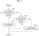
- FIGS. 4 and 5 are flow charts illustrating a diagnosis process of the controller, and FIG. 5 is a flow chart illustrating a failure mode diagnosis process.
- the controller 23 decides whether or not the voltage value ADIN(1) is within the range of the voltage value (namely, within the range of fluctuation) in a state in which the emergency stop switch 14 is in an interruption state as a result of an operation (step S100). In the case where a result of the decision is YES, the controller 23 outputs an emergency stop signal to the dump truck 100 through a transmission device 24 (step S101) and then ends the processing.
- the controller 23 decides whether or not the voltage value ADIN(1) is within a range of the voltage value (namely, within the range of fluctuation) in a state in which the emergency stop switch 14 is not operated (step S110), and ends the processing in the case where the result of the decision is YES.
- step S120 the controller 23 performs a failure mode diagnosis process (step S120).
- the controller 23 has therein a diagnosis map of failure modes in which, in the case where the potential difference between the ground (GND) and the power supply (Vcc) fluctuates within the range of fluctuation set in advance, ranges of fluctuation of the voltage value ADIN(1) in the cases of each of the connection state of the emergency stop switch and the failure modes are set in advance.
- the controller 23 diagnoses a failure mode on the basis of the voltage value ADIN(1) and the diagnosis map (step S121), outputs a result of the diagnosis to the notification device 26 (step S122), and ends the processing.
- the safety switch input diagnosis device includes a circuit 12 formed from a series connection of an emergency stop switch 14 capable of interrupting connection between a first contact 14a and a second contact 14b and a resistor having a resistance value R2 and connected to the first contact 14a or second contact 14b of the emergency stop switch 14, a circuit 11 having a resistor of a resistance value R1 between one end and the other end and connected at the one end to one end of the circuit 12, a line L1 connected at one end to the other end of the circuit 11 and at the other end to a power supply (Vcc), a line L3 connected at one end to the other end of the circuit 12, a circuit 22 having a resistor of a resistance value R5 between one end and the other end and connected at the one end to the other end of the line L3 and at the other end to a ground (GND), a circuit 13 having a resistor of a resistance value R3 between one end and the other end and connected at the one end to the one end of the circuit 12 and
- the resistance values R1 to R3, R4, and R5 of the circuits 11 to 13, 21, and 22 can be set such that the voltage value ADIN(1) indicates values all different from one another in cases of each of the connection state of the emergency stop switch and the failure modes, and the connection state of the emergency stop switch and the failure modes can be diagnosed uniquely on the basis of the voltage value ADIN(1). In other words, an operation of the switch and the failure modes of the circuit relating to the switch can be diagnosed.
- FIGS. 6 to 9 A second embodiment is described with reference to FIGS. 6 to 9 .
- the description of the present embodiment only differences from the first embodiment are described, and like members to those of the first embodiment in the drawings are denoted by like reference characters and description of them is omitted.
- a voltage value ADIN(2) is referred to in addition to the voltage value ADIN(1) in the first embodiment to make it possible to diagnose the connection state of the emergency stop switch and the failure modes with a higher degree of accuracy.
- FIG. 6 is a view depicting a transmission system of a safety switch input diagnosis system according to the present embodiment.
- the transmission system of the safety switch input diagnosis system 200 includes, in addition to the configuration according to the first embodiment, a circuit 27 (ninth circuit) having a resistor (sixth resistor) of a resistance value R6 inserted between the other end of the line L2 (seventh circuit) and the one end of the circuit 21 (eighth circuit), a circuit 28 (tenth circuit) having a resistor (seventh resistor) of a resistance value R7 inserted between the other end of the line L3 (fourth circuit) and the one end of the circuit 22 (fifth circuit), and a circuit 29 (eleventh circuit) having a resistor (eighth resistor) of a resistance value R8 inserted between the other end of the line L1 (third circuit) and the power supply (Vcc).
- a circuit 27 having a resistor (sixth resistor) of a resistance value R6 inserted between the other end of the line L2 (seventh circuit) and the one end of the circuit 21 (eighth circuit)
- a controller 23A diagnoses a connection state of the emergency stop switch 14 and failure modes of the lines L1 to L3 on the basis of the voltage value ADIN(1) at the one end of the circuit 21 and the voltage value ADIN(2) at the one end of the circuit 22, and outputs a result of the diagnosis.
- the transmission system of the safety switch input diagnosis system 200 is generally configured from a switch unit 10 having an emergency stop switch 14, a transmission unit 20A that transmits an emergency stop signal to the reception system, and a plurality of lines L1 to L3 configuring a signal cable that connects the switch unit 10 and the transmission unit 20A to each other.
- the transmission unit 20A is configured including a power supply (Vcc) and the ground (GND), circuits 21 and 22, a controller 23A that diagnoses a connection state of the emergency stop switch 14 and failure modes of the lines L1 to L3 and outputs a result of the analysis, a transmission device 24 that transmits an emergency stop signal that is one of results of diagnosis of the controller 23A through an antenna 25, and a notification device 26 for notifying an operator of information of a failure mode that is one of results of diagnosis of the controller 23A.
- the power supply is connected to a connector 20a for the connection to the outside of the transmission unit 20A.
- the circuit 21 is connected at one end to a connector 20b for the connection to the outside of the transmission unit 20A
- the circuit 22 is connected at one end to a connector 20c.
- a voltage value VREF(H) of the power supply (Vcc), a voltage value VREF(L) of the ground (GND), a voltage value (ADIN(1)) at the one end of the circuit 21 and a voltage value ADIN(2) at the one end of the circuit 22 are inputted.
- the controller 23 diagnoses a connection state of the emergency stop switch 14 and failure modes of the lines L1 to L3 on the basis of the voltage values VREF(H), VREF(L), ADIN(1), and ADIN(2).
- FIGS. 7 and 8 are views depicting values of voltage values inputted to the controller in regard to each of the connection state of the emergency stop switch and the failure modes, and FIG. 7 depicts the voltage value ADIN(1) and FIG. 8 depicts the voltage value ADIN(2).
- the voltage value ADIN(1) and the voltage value ADIN(2) inputted to the controller 23A are found in the cases of each of the connection state of the emergency stop switch and the failure modes as depicted in FIGS. 7 and 8 .
- the resistance values R1 to R3, R4, and R5 of the circuits 11 to 13, 21, and 22 in the present embodiment are set such that, in the cases of each of the connection state of the emergency stop switch and the failure modes, the voltage value ADIN(1) and the voltage value ADIN(2) indicate values different from one another.
- the controller 23A can uniquely diagnose the connection state of the emergency stop switch and the failure modes on the basis of the voltage value ADIN(1) and the voltage value ADIN(2).
- step S220 (correspond to the process in step S120 of the first embodiment) in the diagnosis process is only described.
- FIG. 9 is a flow chart illustrating the failure mode diagnosis process in the diagnosis process in the controller.
- the failure mode diagnosis process is performed (step S220).
- the controller 23A has therein a diagnosis map of failure modes in which, in the case where the potential difference between the ground (GND) and the power supply (Vcc) fluctuates within the range of fluctuation set in advance, ranges of fluctuation of the voltage value ADIN(1) and the voltage value ADIN(2) in the cases of each the connection state of the emergency stop switch and the failure modes are set in advance.
- the controller 23A diagnoses a failure mode on the basis of the voltage value ADIN(1), voltage value ADIN(2) and diagnosis map (step S221), outputs a result of the diagnosis to the notification device 26 (step S222), and ends the processing.
- the configuration of the other part is similar to that of the first embodiment.
- the safety switch input diagnosis device is configured such that the voltage value ADIN(2) is referred to in addition to the voltage value ADIN(1) in the first embodiment, the connection state of the emergency stop switch and the failure modes can be diagnosed with a higher degree of accuracy.
- Each of the configurations, functions, and so forth described above may be partly or entire implemented, for example, by designing the same with an integrated circuit or the like.
- the configurations, functions, and so forth described above may be implemented by software by causing a processor to interpret and execute a program for implementing each of the functions.
- the present embodiments exemplify a case in which the switch unit 10 and the transmission units 20 and 20A are configured as separate members and connected to each other by the lines L1 to L3, this is not restrictive, and the switch unit 10 and the transmission units 20 and 20A may be configured integrally.
- the lines L1 to L3 are formed on a circuit board, and the controllers 23 and 23A diagnoses the connection state of the emergency stop switch 14 and the failure modes of the lines L1 to L3.
Landscapes
- Engineering & Computer Science (AREA)
- Transportation (AREA)
- Mechanical Engineering (AREA)
- Power Engineering (AREA)
- Automation & Control Theory (AREA)
- Physics & Mathematics (AREA)
- Sustainable Development (AREA)
- Sustainable Energy (AREA)
- Life Sciences & Earth Sciences (AREA)
- Human Computer Interaction (AREA)
- Electromagnetism (AREA)
- General Physics & Mathematics (AREA)
- Valves And Accessory Devices For Braking Systems (AREA)
- Safety Devices In Control Systems (AREA)
- Electric Propulsion And Braking For Vehicles (AREA)
- Testing And Monitoring For Control Systems (AREA)
Claims (5)
- Sicherheitsschaltereingabediagnosevorrichtung (200), umfassend eine Schaltereinheit (10) und eine Übertragungseinheit (20), wobei die Sicherheitsschaltereingabediagnosevorrichtung (200) umfasst:in der Schaltereinheit (10) eine erste Schaltung (12), die ein Ende und ein anderes Ende aufweist und aus einer Reihenschaltung eines Schalters (SW), der mit dem anderen Ende der ersten Schaltung (12) verbunden ist und in der Lage ist, eine Verbindung zwischen einem ersten Kontakt (14a) und einem zweiten Kontakt (14b) zu unterbrechen, und einer Leitung gebildet ist, die einen ersten Widerstand (R2) aufweist, der zwischen dem zweiten Kontakt des Schalters (SW) und dem einen Ende der ersten Schaltung (12) verbunden ist;in der Schaltereinheit (10) eine zweite Schaltung (11), die einen zweiten Widerstand (R1) zwischen einem Ende und einem anderen Ende aufweist und an dem einen Ende mit dem einen Ende der ersten Schaltung (12) und an dem anderen Ende mit einem ersten Verbinder (10a) der Schaltereinheit (10) verbunden ist;eine dritte Schaltung, die eine Leitung (L1) ist, die an einem Ende mit dem ersten Verbinder (10a) und an einem anderen Ende mit einem vierten Verbinder (20a) der Übertragungseinheit (20) verbunden ist, der mit einer Stromversorgung (Vcc) verbunden ist;eine vierte Schaltung, die eine Leitung (L3) ist, die an einem Ende mit einem dritten Verbinder (10c) der Schaltereinheit (10) verbunden ist, der mit dem anderen Ende der ersten Schaltung (12) verbunden ist;in der Übertragungseinheit (20) eine fünfte Schaltung (22), die einen dritten Widerstand (R5) zwischen einem Ende und einem anderen Ende aufweist und an dem einen Ende mit einem sechsten Verbinder (20c) der Übertragungseinheit (20) verbunden ist, der mit dem anderen Ende der vierten Schaltung (L3) und an dem anderen Ende mit einer Masse (GND) verbunden ist;in der Schaltereinheit (10) eine sechste Schaltung (13), die einen vierten Widerstand (R3) zwischen einem Ende und einem anderen Ende aufweist und an dem einen Ende mit dem einen Ende der ersten Schaltung (12) und an dem anderen Ende mit dem anderen Ende der ersten Schaltung (12) verbunden ist;eine siebte Schaltung, die eine Leitung (L2) ist, die an einem Ende mit einem zweiten Verbinder (10b) der Schaltereinheit (10) verbunden ist, der mit dem einen Ende der ersten Schaltung (12) verbunden ist;in der Übertragungseinheit (20) eine achte Schaltung (21), die einen fünften Widerstand (R4) zwischen einem Ende und einem anderen Ende aufweist und an dem einen Ende mit einem fünften Verbinder (20b) der Übertragungseinheit (20), der mit dem anderen Ende der siebten Schaltung (L2) verbunden ist, und an dem anderen Ende mit der Masse (GND) verbunden ist; undin der Übertragungseinheit (20) eine Steuerung (23), die mit dem einen Ende der achten Schaltung (21) verbunden ist und konfiguriert ist, um einen Verbindungszustand des Schalters (SW) und Fehlermodi der dritten, der vierten und der siebten Schaltung auf einer Basis eines Spannungswerts an dem einen Ende der achten Schaltung (21) zu diagnostizieren und ein Diagnoseergebnis auszugeben.
- Sicherheitsschaltereingabediagnosevorrichtung nach Anspruch 1, wobei Widerstandswerte der ersten bis fünften Widerstände (R1 - R5) so eingestellt sind, dass der Spannungswert an dem einen Ende der achten Schaltung (21), der in die Steuerung eingegeben wird, jeden von unterschiedlichen Werten voneinander gemäß jedem von Zuständen einer Unterbrechung der Verbindung des Schalters und eines Kurzschlusses auf hohem Niveau, eines Kurzschlusses auf niedrigem Niveau, einer Unterbrechung und eines Kurzschlusses zwischen den Schaltungen individuell der dritten, der vierten und der siebten Schaltung angibt.
- Sicherheitsschaltereingabediagnosevorrichtung nach Anspruch 1, wobei Widerstandswerte der ersten bis fünften Widerstände (R1 bis R5) so eingestellt sind, dass in einem Fall, in dem eine Potentialdifferenz zwischen der Masse und der Stromversorgung innerhalb eines im Voraus eingestellten Schwankungsbereichs schwankt, der Schwankungsbereich, der mit dem Spannungswert an dem einen Ende der achten Schaltung (21) auftritt, der in die Steuerung eingegeben wird, in und gemäß jedem von Zuständen einer Unterbrechung der Verbindung des Schalters und eines Kurzschlusses auf hohem Niveau, eines Kurzschlusses auf niedrigem Niveau, einer Unterbrechung und eines Kurzschlusses zwischen den Schaltungen individuell der dritten, der vierten und der siebten Schaltung unabhängig ist.
- Sicherheitsschaltereingabediagnosevorrichtung nach einem der Ansprüche 1 oder 2, ferner umfassend:eine neunte Schaltung (27), die einen sechsten Widerstand (R6) aufweist, der zwischen dem fünften Verbinder (20b) und dem einen Ende der achten Schaltung (21) eingefügt ist;eine zehnte Schaltung (28), die einen siebten Widerstand (R7) aufweist, der zwischen dem sechsten Verbinder (20c) und dem einen Ende der fünften Schaltung (22) eingefügt ist; undeine elfte Schaltung (29), die einen achten Widerstand (R8) aufweist, der zwischen dem vierten Verbinder (20a) und der Stromversorgung (Vcc) eingefügt ist, wobeidie Steuerung (23) konfiguriert ist, um den Verbindungszustand des Schalters (SW) und die Fehlermodi der dritten, der vierten und der siebten Schaltung auf einer Basis eines Spannungswerts an dem einen Ende der achten Schaltung (21) und eines Spannungswerts an dem einen Ende der fünften Schaltung (22) zu diagnostizieren und ein Diagnoseergebnis auszugeben.
- Arbeitsmaschine (100), umfassend:einen Fahrmotor, der durch elektrische Leistung angetrieben wird, die durch einen Generator erzeugt wird, der durch eine Brennkraftmaschine angetrieben wird;ein Antriebsrad (2, 3), das durch den Fahrmotor angetrieben wird;eine Maschinenkörpersteuerung, die konfiguriert ist, um eine Aktion der Brennkraftmaschine, des Generators, des Fahrmotors und eines Bremssystems, das das Antriebsrad bremst, zu steuern; undein Sicherheitsschaltereingabediagnosesystem, das die Sicherheitsschaltereingabediagnosevorrichtung (200) nach Anspruch 1, eine Übertragungsvorrichtung, die konfiguriert ist, um ein Diagnoseergebnis der Sicherheitsschaltereingabediagnosevorrichtung zu übertragen, eine Empfangsvorrichtung, die konfiguriert ist, um das von der Übertragungsvorrichtung übertragene Diagnoseergebnis zu empfangen, und eine Empfangssteuerung, die konfiguriert ist, um das von der Empfangsvorrichtung empfangene Diagnoseergebnis an die Maschinenkörpersteuerung auszugeben, umfasst, wobei die Maschinenkörpersteuerung konfiguriert ist, um eine Aktion der Brennkraftmaschine, des Generators, des Fahrmotors und des Bremssystems auf einer Basis des von der Empfangssteuerung ausgegebenen Diagnoseergebnisses zu steuern.
Applications Claiming Priority (2)
| Application Number | Priority Date | Filing Date | Title |
|---|---|---|---|
| JP2018181053A JP6966408B2 (ja) | 2018-09-26 | 2018-09-26 | 安全スイッチ入力診断装置及びこれを用いた作業機械 |
| PCT/JP2019/026729 WO2020066204A1 (ja) | 2018-09-26 | 2019-07-04 | 安全スイッチ入力診断装置及びこれを用いた作業機械 |
Publications (3)
| Publication Number | Publication Date |
|---|---|
| EP3751297A1 EP3751297A1 (de) | 2020-12-16 |
| EP3751297A4 EP3751297A4 (de) | 2021-12-15 |
| EP3751297B1 true EP3751297B1 (de) | 2024-10-02 |
Family
ID=69949789
Family Applications (1)
| Application Number | Title | Priority Date | Filing Date |
|---|---|---|---|
| EP19866992.1A Active EP3751297B1 (de) | 2018-09-26 | 2019-07-04 | Sicherheitsschaltereingangsdiagnosevorrichtung und arbeitsmaschine damit |
Country Status (5)
| Country | Link |
|---|---|
| US (1) | US11562864B2 (de) |
| EP (1) | EP3751297B1 (de) |
| JP (1) | JP6966408B2 (de) |
| CN (1) | CN111771130B (de) |
| WO (1) | WO2020066204A1 (de) |
Families Citing this family (3)
| Publication number | Priority date | Publication date | Assignee | Title |
|---|---|---|---|---|
| DE102020126777A1 (de) * | 2020-10-13 | 2022-04-14 | Valeo Schalter Und Sensoren Gmbh | Eingabevorrichtung für ein Kraftfahrzeug mit einer spannungsbasierten Fehlererkennung |
| TWI787057B (zh) * | 2021-09-30 | 2022-12-11 | 財團法人工業技術研究院 | 車用控制裝置及其方法 |
| CN119171898B (zh) * | 2024-11-20 | 2025-05-02 | 浙江国利信安科技有限公司 | 用于数字量输入输出电路的诊断电路 |
Family Cites Families (18)
| Publication number | Priority date | Publication date | Assignee | Title |
|---|---|---|---|---|
| JP2001133502A (ja) * | 1999-11-01 | 2001-05-18 | Unisia Jecs Corp | 異常検出装置 |
| JP2006119239A (ja) * | 2004-10-20 | 2006-05-11 | Kyocera Mita Corp | 検知装置、及び画像形成装置 |
| JP2008159423A (ja) | 2006-12-25 | 2008-07-10 | Tokyo Sensor:Kk | スイッチ状態検出装置 |
| JP5417257B2 (ja) * | 2010-05-31 | 2014-02-12 | 富士通コンポーネント株式会社 | 検出回路 |
| DE102010030826A1 (de) * | 2010-07-01 | 2012-01-05 | Robert Bosch Gmbh | Verfahren und Schaltungsanordnung zur Diagnose eines Lastpfades in einem Fahrzeug |
| CN201829385U (zh) * | 2010-07-13 | 2011-05-11 | 北汽福田汽车股份有限公司 | 带诊断功能的按键开关和按键开关装置 |
| JP5631188B2 (ja) | 2010-12-20 | 2014-11-26 | カルソニックカンセイ株式会社 | スイッチ装置 |
| JP5655720B2 (ja) * | 2011-06-30 | 2015-01-21 | 株式会社デンソー | 絶縁不良診断装置 |
| JP2013246985A (ja) | 2012-05-25 | 2013-12-09 | Honda Elesys Co Ltd | 異常検出装置及び異常検出方法 |
| CN103852680A (zh) * | 2012-12-07 | 2014-06-11 | 中国核动力研究设计院 | 一种检测开关量信号传输电路断线的装置及其方法 |
| KR101562016B1 (ko) * | 2013-08-29 | 2015-11-18 | 주식회사 엘지화학 | 셀 밸런싱 스위치의 고장 진단 장치 및 방법 |
| CN103487704A (zh) * | 2013-10-12 | 2014-01-01 | 广西柳工机械股份有限公司 | 有线路故障诊断功能的开关 |
| US9599216B2 (en) * | 2014-04-29 | 2017-03-21 | GM Global Technology Operations LLC | Push-button shifter assembly with button state determination logic |
| JP6451323B2 (ja) | 2015-01-06 | 2019-01-16 | 株式会社デンソーウェーブ | ロボットの配線方法 |
| US9645185B2 (en) * | 2015-03-05 | 2017-05-09 | Ford Global Technologies, Llc | AC traction motor fault detection using DC bus leakage hardware |
| CN106855589B (zh) * | 2015-12-08 | 2020-07-31 | 台达电子工业股份有限公司 | 电源分配器及其故障检测方法 |
| US10035422B2 (en) * | 2016-06-14 | 2018-07-31 | Ford Global Technologies, Llc | Self-limiting active discharge circuit for electric vehicle inverter |
| KR101887903B1 (ko) * | 2016-11-11 | 2018-09-06 | 현대오트론 주식회사 | 저항성 센서의 고장 진단 장치 및 진단 방법 |
-
2018
- 2018-09-26 JP JP2018181053A patent/JP6966408B2/ja active Active
-
2019
- 2019-07-04 CN CN201980015468.9A patent/CN111771130B/zh active Active
- 2019-07-04 US US16/979,339 patent/US11562864B2/en active Active
- 2019-07-04 WO PCT/JP2019/026729 patent/WO2020066204A1/ja not_active Ceased
- 2019-07-04 EP EP19866992.1A patent/EP3751297B1/de active Active
Also Published As
| Publication number | Publication date |
|---|---|
| US11562864B2 (en) | 2023-01-24 |
| WO2020066204A1 (ja) | 2020-04-02 |
| CN111771130B (zh) | 2023-05-02 |
| JP2020054108A (ja) | 2020-04-02 |
| EP3751297A1 (de) | 2020-12-16 |
| US20210005402A1 (en) | 2021-01-07 |
| CN111771130A (zh) | 2020-10-13 |
| EP3751297A4 (de) | 2021-12-15 |
| JP6966408B2 (ja) | 2021-11-17 |
Similar Documents
| Publication | Publication Date | Title |
|---|---|---|
| EP3751297B1 (de) | Sicherheitsschaltereingangsdiagnosevorrichtung und arbeitsmaschine damit | |
| US9783227B2 (en) | Vehicle steering device | |
| US11400971B2 (en) | Rotary electric machine control device and method | |
| EP1219525A2 (de) | Redundates Steer-by-wire-Lenksystem | |
| FI120990B (fi) | Menetelmä ja järjestely turvatoiminnon aktivoimiseen tarkoitetun kytkimen liitäntöjen valvomiseksi | |
| US8457824B2 (en) | Embedded controller frequency inputs re-used for speed sensor diagnostics | |
| CN114735073B (zh) | 一种避免自动驾驶车辆转向系统故障的装置及其控制方法 | |
| US6636009B2 (en) | Fault-tolerant electromechanical actuating device | |
| CN211416974U (zh) | 整车及电池管理一体化系统 | |
| CN115675622A (zh) | 转向系统 | |
| US20060097852A1 (en) | System and method for power and data delivery on a machine | |
| CN113650499A (zh) | 高压互锁故障检测与处理方法及系统 | |
| CN120276497A (zh) | 一种转向系统的硬件在环测试系统 | |
| CN111619477B (zh) | 用于机动车通信的通信系统和通信方法 | |
| JP2009029196A (ja) | 電動パワーステアリング装置 | |
| EP3929597B1 (de) | Anordnung zur überwachung einer elektrischen isolierung | |
| KR200186838Y1 (ko) | 전기차 구동모터 제어시스템 | |
| JP6914003B2 (ja) | 電子制御装置 | |
| US20240376690A1 (en) | High voltage interlock loop for electric implements of power machines | |
| CN113320016A (zh) | 控制装置、方法、系统和电动搅拌车 | |
| US12236724B2 (en) | Reprogramming tool | |
| JPH0248279Y2 (de) | ||
| KR101252768B1 (ko) | 차량 브레이크 시스템 및 제어 방법 | |
| JP2025110149A (ja) | 検査システムおよび検査方法 | |
| CN117207995A (zh) | 无人矿车线控底盘的控制方法、系统和无人矿车 |
Legal Events
| Date | Code | Title | Description |
|---|---|---|---|
| STAA | Information on the status of an ep patent application or granted ep patent |
Free format text: STATUS: THE INTERNATIONAL PUBLICATION HAS BEEN MADE |
|
| PUAI | Public reference made under article 153(3) epc to a published international application that has entered the european phase |
Free format text: ORIGINAL CODE: 0009012 |
|
| STAA | Information on the status of an ep patent application or granted ep patent |
Free format text: STATUS: REQUEST FOR EXAMINATION WAS MADE |
|
| 17P | Request for examination filed |
Effective date: 20200910 |
|
| AK | Designated contracting states |
Kind code of ref document: A1 Designated state(s): AL AT BE BG CH CY CZ DE DK EE ES FI FR GB GR HR HU IE IS IT LI LT LU LV MC MK MT NL NO PL PT RO RS SE SI SK SM TR |
|
| AX | Request for extension of the european patent |
Extension state: BA ME |
|
| A4 | Supplementary search report drawn up and despatched |
Effective date: 20211115 |
|
| RIC1 | Information provided on ipc code assigned before grant |
Ipc: B60L 3/04 20060101ALI20211109BHEP Ipc: G01R 31/327 20060101ALI20211109BHEP Ipc: B60L 50/10 20190101ALI20211109BHEP Ipc: B60L 3/00 20190101ALI20211109BHEP Ipc: G01R 31/08 20200101AFI20211109BHEP |
|
| DAV | Request for validation of the european patent (deleted) | ||
| DAX | Request for extension of the european patent (deleted) | ||
| GRAP | Despatch of communication of intention to grant a patent |
Free format text: ORIGINAL CODE: EPIDOSNIGR1 |
|
| STAA | Information on the status of an ep patent application or granted ep patent |
Free format text: STATUS: GRANT OF PATENT IS INTENDED |
|
| INTG | Intention to grant announced |
Effective date: 20240404 |
|
| GRAS | Grant fee paid |
Free format text: ORIGINAL CODE: EPIDOSNIGR3 |
|
| GRAA | (expected) grant |
Free format text: ORIGINAL CODE: 0009210 |
|
| STAA | Information on the status of an ep patent application or granted ep patent |
Free format text: STATUS: THE PATENT HAS BEEN GRANTED |
|
| AK | Designated contracting states |
Kind code of ref document: B1 Designated state(s): AL AT BE BG CH CY CZ DE DK EE ES FI FR GB GR HR HU IE IS IT LI LT LU LV MC MK MT NL NO PL PT RO RS SE SI SK SM TR |
|
| REG | Reference to a national code |
Ref country code: GB Ref legal event code: FG4D |
|
| REG | Reference to a national code |
Ref country code: CH Ref legal event code: EP |
|
| REG | Reference to a national code |
Ref country code: IE Ref legal event code: FG4D |
|
| REG | Reference to a national code |
Ref country code: DE Ref legal event code: R096 Ref document number: 602019059855 Country of ref document: DE |
|
| REG | Reference to a national code |
Ref country code: LT Ref legal event code: MG9D |
|
| REG | Reference to a national code |
Ref country code: NL Ref legal event code: MP Effective date: 20241002 |
|
| REG | Reference to a national code |
Ref country code: AT Ref legal event code: MK05 Ref document number: 1728859 Country of ref document: AT Kind code of ref document: T Effective date: 20241002 |
|
| PG25 | Lapsed in a contracting state [announced via postgrant information from national office to epo] |
Ref country code: NL Free format text: LAPSE BECAUSE OF FAILURE TO SUBMIT A TRANSLATION OF THE DESCRIPTION OR TO PAY THE FEE WITHIN THE PRESCRIBED TIME-LIMIT Effective date: 20241002 |
|
| PG25 | Lapsed in a contracting state [announced via postgrant information from national office to epo] |
Ref country code: NL Free format text: LAPSE BECAUSE OF FAILURE TO SUBMIT A TRANSLATION OF THE DESCRIPTION OR TO PAY THE FEE WITHIN THE PRESCRIBED TIME-LIMIT Effective date: 20241002 |
|
| PG25 | Lapsed in a contracting state [announced via postgrant information from national office to epo] |
Ref country code: PT Free format text: LAPSE BECAUSE OF FAILURE TO SUBMIT A TRANSLATION OF THE DESCRIPTION OR TO PAY THE FEE WITHIN THE PRESCRIBED TIME-LIMIT Effective date: 20250203 Ref country code: HR Free format text: LAPSE BECAUSE OF FAILURE TO SUBMIT A TRANSLATION OF THE DESCRIPTION OR TO PAY THE FEE WITHIN THE PRESCRIBED TIME-LIMIT Effective date: 20241002 Ref country code: IS Free format text: LAPSE BECAUSE OF FAILURE TO SUBMIT A TRANSLATION OF THE DESCRIPTION OR TO PAY THE FEE WITHIN THE PRESCRIBED TIME-LIMIT Effective date: 20250202 |
|
| PG25 | Lapsed in a contracting state [announced via postgrant information from national office to epo] |
Ref country code: FI Free format text: LAPSE BECAUSE OF FAILURE TO SUBMIT A TRANSLATION OF THE DESCRIPTION OR TO PAY THE FEE WITHIN THE PRESCRIBED TIME-LIMIT Effective date: 20241002 |
|
| PG25 | Lapsed in a contracting state [announced via postgrant information from national office to epo] |
Ref country code: BG Free format text: LAPSE BECAUSE OF FAILURE TO SUBMIT A TRANSLATION OF THE DESCRIPTION OR TO PAY THE FEE WITHIN THE PRESCRIBED TIME-LIMIT Effective date: 20241002 |
|
| PG25 | Lapsed in a contracting state [announced via postgrant information from national office to epo] |
Ref country code: ES Free format text: LAPSE BECAUSE OF FAILURE TO SUBMIT A TRANSLATION OF THE DESCRIPTION OR TO PAY THE FEE WITHIN THE PRESCRIBED TIME-LIMIT Effective date: 20241002 |
|
| PG25 | Lapsed in a contracting state [announced via postgrant information from national office to epo] |
Ref country code: NO Free format text: LAPSE BECAUSE OF FAILURE TO SUBMIT A TRANSLATION OF THE DESCRIPTION OR TO PAY THE FEE WITHIN THE PRESCRIBED TIME-LIMIT Effective date: 20250102 |
|
| PG25 | Lapsed in a contracting state [announced via postgrant information from national office to epo] |
Ref country code: AT Free format text: LAPSE BECAUSE OF FAILURE TO SUBMIT A TRANSLATION OF THE DESCRIPTION OR TO PAY THE FEE WITHIN THE PRESCRIBED TIME-LIMIT Effective date: 20241002 Ref country code: LV Free format text: LAPSE BECAUSE OF FAILURE TO SUBMIT A TRANSLATION OF THE DESCRIPTION OR TO PAY THE FEE WITHIN THE PRESCRIBED TIME-LIMIT Effective date: 20241002 Ref country code: GR Free format text: LAPSE BECAUSE OF FAILURE TO SUBMIT A TRANSLATION OF THE DESCRIPTION OR TO PAY THE FEE WITHIN THE PRESCRIBED TIME-LIMIT Effective date: 20250103 |
|
| PG25 | Lapsed in a contracting state [announced via postgrant information from national office to epo] |
Ref country code: CZ Free format text: LAPSE BECAUSE OF FAILURE TO SUBMIT A TRANSLATION OF THE DESCRIPTION OR TO PAY THE FEE WITHIN THE PRESCRIBED TIME-LIMIT Effective date: 20241002 Ref country code: PL Free format text: LAPSE BECAUSE OF FAILURE TO SUBMIT A TRANSLATION OF THE DESCRIPTION OR TO PAY THE FEE WITHIN THE PRESCRIBED TIME-LIMIT Effective date: 20241002 |
|
| PG25 | Lapsed in a contracting state [announced via postgrant information from national office to epo] |
Ref country code: RS Free format text: LAPSE BECAUSE OF FAILURE TO SUBMIT A TRANSLATION OF THE DESCRIPTION OR TO PAY THE FEE WITHIN THE PRESCRIBED TIME-LIMIT Effective date: 20250102 |
|
| PG25 | Lapsed in a contracting state [announced via postgrant information from national office to epo] |
Ref country code: SM Free format text: LAPSE BECAUSE OF FAILURE TO SUBMIT A TRANSLATION OF THE DESCRIPTION OR TO PAY THE FEE WITHIN THE PRESCRIBED TIME-LIMIT Effective date: 20241002 |
|
| REG | Reference to a national code |
Ref country code: DE Ref legal event code: R097 Ref document number: 602019059855 Country of ref document: DE |
|
| PG25 | Lapsed in a contracting state [announced via postgrant information from national office to epo] |
Ref country code: DK Free format text: LAPSE BECAUSE OF FAILURE TO SUBMIT A TRANSLATION OF THE DESCRIPTION OR TO PAY THE FEE WITHIN THE PRESCRIBED TIME-LIMIT Effective date: 20241002 |
|
| PG25 | Lapsed in a contracting state [announced via postgrant information from national office to epo] |
Ref country code: EE Free format text: LAPSE BECAUSE OF FAILURE TO SUBMIT A TRANSLATION OF THE DESCRIPTION OR TO PAY THE FEE WITHIN THE PRESCRIBED TIME-LIMIT Effective date: 20241002 |
|
| PG25 | Lapsed in a contracting state [announced via postgrant information from national office to epo] |
Ref country code: RO Free format text: LAPSE BECAUSE OF FAILURE TO SUBMIT A TRANSLATION OF THE DESCRIPTION OR TO PAY THE FEE WITHIN THE PRESCRIBED TIME-LIMIT Effective date: 20241002 |
|
| PG25 | Lapsed in a contracting state [announced via postgrant information from national office to epo] |
Ref country code: SK Free format text: LAPSE BECAUSE OF FAILURE TO SUBMIT A TRANSLATION OF THE DESCRIPTION OR TO PAY THE FEE WITHIN THE PRESCRIBED TIME-LIMIT Effective date: 20241002 |
|
| PG25 | Lapsed in a contracting state [announced via postgrant information from national office to epo] |
Ref country code: IT Free format text: LAPSE BECAUSE OF FAILURE TO SUBMIT A TRANSLATION OF THE DESCRIPTION OR TO PAY THE FEE WITHIN THE PRESCRIBED TIME-LIMIT Effective date: 20241002 |
|
| PLBE | No opposition filed within time limit |
Free format text: ORIGINAL CODE: 0009261 |
|
| STAA | Information on the status of an ep patent application or granted ep patent |
Free format text: STATUS: NO OPPOSITION FILED WITHIN TIME LIMIT |
|
| PG25 | Lapsed in a contracting state [announced via postgrant information from national office to epo] |
Ref country code: SE Free format text: LAPSE BECAUSE OF FAILURE TO SUBMIT A TRANSLATION OF THE DESCRIPTION OR TO PAY THE FEE WITHIN THE PRESCRIBED TIME-LIMIT Effective date: 20241002 |
|
| 26N | No opposition filed |
Effective date: 20250703 |
|
| PGFP | Annual fee paid to national office [announced via postgrant information from national office to epo] |
Ref country code: DE Payment date: 20250528 Year of fee payment: 7 |
|
| REG | Reference to a national code |
Ref country code: CH Ref legal event code: H13 Free format text: ST27 STATUS EVENT CODE: U-0-0-H10-H13 (AS PROVIDED BY THE NATIONAL OFFICE) Effective date: 20260224 |
|
| PG25 | Lapsed in a contracting state [announced via postgrant information from national office to epo] |
Ref country code: LU Free format text: LAPSE BECAUSE OF NON-PAYMENT OF DUE FEES Effective date: 20250704 |
|
| GBPC | Gb: european patent ceased through non-payment of renewal fee |
Effective date: 20250704 |
|
| REG | Reference to a national code |
Ref country code: BE Ref legal event code: MM Effective date: 20250731 |
|
| PG25 | Lapsed in a contracting state [announced via postgrant information from national office to epo] |
Ref country code: GB Free format text: LAPSE BECAUSE OF NON-PAYMENT OF DUE FEES Effective date: 20250704 |
|
| PG25 | Lapsed in a contracting state [announced via postgrant information from national office to epo] |
Ref country code: BE Free format text: LAPSE BECAUSE OF NON-PAYMENT OF DUE FEES Effective date: 20250731 |
|
| PG25 | Lapsed in a contracting state [announced via postgrant information from national office to epo] |
Ref country code: FR Free format text: LAPSE BECAUSE OF NON-PAYMENT OF DUE FEES Effective date: 20250731 |
|
| PG25 | Lapsed in a contracting state [announced via postgrant information from national office to epo] |
Ref country code: CH Free format text: LAPSE BECAUSE OF NON-PAYMENT OF DUE FEES Effective date: 20250731 |