EP3751195B1 - Stützbalkenanordnung zum stützen einer rauchgasleitung - Google Patents
Stützbalkenanordnung zum stützen einer rauchgasleitung Download PDFInfo
- Publication number
- EP3751195B1 EP3751195B1 EP20397504.0A EP20397504A EP3751195B1 EP 3751195 B1 EP3751195 B1 EP 3751195B1 EP 20397504 A EP20397504 A EP 20397504A EP 3751195 B1 EP3751195 B1 EP 3751195B1
- Authority
- EP
- European Patent Office
- Prior art keywords
- supporting beam
- supporting
- height
- flue gas
- gas duct
- Prior art date
- Legal status (The legal status is an assumption and is not a legal conclusion. Google has not performed a legal analysis and makes no representation as to the accuracy of the status listed.)
- Active
Links
Images


Classifications
-
- F—MECHANICAL ENGINEERING; LIGHTING; HEATING; WEAPONS; BLASTING
- F22—STEAM GENERATION
- F22B—METHODS OF STEAM GENERATION; STEAM BOILERS
- F22B37/00—Component parts or details of steam boilers
- F22B37/02—Component parts or details of steam boilers applicable to more than one kind or type of steam boiler
- F22B37/24—Supporting, suspending or setting arrangements, e.g. heat shielding
-
- F—MECHANICAL ENGINEERING; LIGHTING; HEATING; WEAPONS; BLASTING
- F22—STEAM GENERATION
- F22B—METHODS OF STEAM GENERATION; STEAM BOILERS
- F22B31/00—Modifications of boiler construction, or of tube systems, dependent on installation of combustion apparatus; Arrangements or dispositions of combustion apparatus
- F22B31/0007—Modifications of boiler construction, or of tube systems, dependent on installation of combustion apparatus; Arrangements or dispositions of combustion apparatus with combustion in a fluidized bed
- F22B31/0084—Modifications of boiler construction, or of tube systems, dependent on installation of combustion apparatus; Arrangements or dispositions of combustion apparatus with combustion in a fluidized bed with recirculation of separated solids or with cooling of the bed particles outside the combustion bed
-
- F—MECHANICAL ENGINEERING; LIGHTING; HEATING; WEAPONS; BLASTING
- F22—STEAM GENERATION
- F22B—METHODS OF STEAM GENERATION; STEAM BOILERS
- F22B37/00—Component parts or details of steam boilers
- F22B37/001—Steam generators built-up from pre-fabricated elements
-
- F—MECHANICAL ENGINEERING; LIGHTING; HEATING; WEAPONS; BLASTING
- F22—STEAM GENERATION
- F22B—METHODS OF STEAM GENERATION; STEAM BOILERS
- F22B37/00—Component parts or details of steam boilers
- F22B37/008—Adaptations for flue-gas purification in steam generators
-
- F—MECHANICAL ENGINEERING; LIGHTING; HEATING; WEAPONS; BLASTING
- F22—STEAM GENERATION
- F22B—METHODS OF STEAM GENERATION; STEAM BOILERS
- F22B37/00—Component parts or details of steam boilers
- F22B37/02—Component parts or details of steam boilers applicable to more than one kind or type of steam boiler
- F22B37/10—Water tubes; Accessories therefor
- F22B37/20—Supporting arrangements, e.g. for securing water-tube sets
- F22B37/201—Suspension and securing arrangements for walls built-up from tubes
-
- F—MECHANICAL ENGINEERING; LIGHTING; HEATING; WEAPONS; BLASTING
- F22—STEAM GENERATION
- F22B—METHODS OF STEAM GENERATION; STEAM BOILERS
- F22B37/00—Component parts or details of steam boilers
- F22B37/02—Component parts or details of steam boilers applicable to more than one kind or type of steam boiler
- F22B37/06—Flue or fire tubes; Accessories therefor, e.g. fire-tube inserts
-
- F—MECHANICAL ENGINEERING; LIGHTING; HEATING; WEAPONS; BLASTING
- F22—STEAM GENERATION
- F22B—METHODS OF STEAM GENERATION; STEAM BOILERS
- F22B37/00—Component parts or details of steam boilers
- F22B37/02—Component parts or details of steam boilers applicable to more than one kind or type of steam boiler
- F22B37/10—Water tubes; Accessories therefor
- F22B37/20—Supporting arrangements, e.g. for securing water-tube sets
- F22B37/202—Suspension and securing arrangements for contact heating surfaces
-
- F—MECHANICAL ENGINEERING; LIGHTING; HEATING; WEAPONS; BLASTING
- F22—STEAM GENERATION
- F22B—METHODS OF STEAM GENERATION; STEAM BOILERS
- F22B37/00—Component parts or details of steam boilers
- F22B37/02—Component parts or details of steam boilers applicable to more than one kind or type of steam boiler
- F22B37/10—Water tubes; Accessories therefor
- F22B37/20—Supporting arrangements, e.g. for securing water-tube sets
- F22B37/208—Backstay arrangements
-
- F—MECHANICAL ENGINEERING; LIGHTING; HEATING; WEAPONS; BLASTING
- F23—COMBUSTION APPARATUS; COMBUSTION PROCESSES
- F23C—METHODS OR APPARATUS FOR COMBUSTION USING FLUID FUEL OR SOLID FUEL SUSPENDED IN A CARRIER GAS OR AIR
- F23C2202/00—Fluegas recirculation
Definitions
- the solution to be presented relates to a supporting beam arrangement for supporting a flue gas duct.
- the supporting beam arrangement is connected to a support frame of the flue gas duct of a power boiler in particular.
- the support frame may further be adapted to support the power boiler and include supporting beams and pillars to support the flue gas duct to the ground.
- Power boiler systems especially steam boilers of CFB (circulating fluidized bed) and BFB (bubbling fluidized bed) design, have a furnace with heat transfer surfaces and for burning e.g. conventional fuel, biomass or municipal solid waste.
- Hot flue gases produced in the furnace are conveyed to a flue gas duct constituting a vertical convection pass through which the flue gases flow, e.g. downwards.
- Heat exchangers including banks of tubes and located within the convection pass provide heat transfer surfaces which transfer heat from the flue gases to the medium flowing inside the tubes, the medium being steam, water or air.
- the heat exchangers of the convection pass may include preheaters, e.g. an economiser adapted to cool down the flue gases and preheat water fed to a water circulation system of the power boiler, and an air heater downstream of the economiser, for preheating combustion air to be conveyed into the furnace.
- Supporting beam arrangements for supporting the flue gas duct may include beams that extend through the flue gas duct in such a way that the beams are exposed to hot flue gases. Furthermore, the supporting beam arrangements may include beams, e.g. primary, secondary and tertiary beams that are connected to or supported on top of each other. Therefore, the design of supporting beams for use in such circumstances must be optimized when e.g. the strength of the beam is critical, or the total height and structure of the support frame or flue gas duct need to be taken into consideration.
- Document EP 2927581 A1 discloses a power steam boiler comprising a flue gas duct with heat exchangers and a boiler house, i.e. a support frame, with beams and columns for supporting the flue gas duct.
- a supporting beam arrangement for supporting a flue gas duct according to the preamble of claim 1 is disclosed in document US 2012/0279596 A1 .
- a supporting beam arrangement for supporting a flue gas duct according to the invention is presented in claim 1.
- the flue gas duct is adapted to convey flue gases and the supporting beam arrangement is adapted to support the flue gas duct.
- the supporting beam arrangement comprises two substantially horizontal first supporting beams that are substantially parallel and situated on two opposite sides of the flue gas duct, the first supporting beams being separated by a distance from the flue gas duct, and the first supporting beams including two opposite ends that are connected to a support frame of the flue gas duct.
- the first supporting beam defines a substantially horizontal top surface at a first height.
- the supporting beam arrangement further comprises a substantially horizontal second supporting beam defining two opposite ends that are supported by the first supporting beams.
- the second supporting beam extends through the flue gas duct in such a way that the second supporting beam is exposed to flue gases and flue gas duct is supported by the second supporting beam.
- the second supporting beam includes two end sections, each end section horizontally extending outside the flue gas duct between the flue gas duct and one of the first supporting beams, at least one or each one of the end sections defining a substantially horizontal top surface located at a second height. The second height is less than the first height.
- At least one or each one of the first supporting beams comprises an opening, in which opening one of the two opposite ends of the second supporting beam is placed to rest on the first supporting beam in such a way that loads incurred by the weight of the flue gas duct are transmitted to the first supporting beam.
- the supporting beam arrangement further comprises a substantially horizontal intermediate supporting beam that is substantially parallel with the first supporting beams and substantially perpendicular to the second supporting beam.
- the intermediate supporting beam is supported by the support frame.
- the intermediate supporting beam is in a vertical direction located above the top surface of one of the end sections.
- the supporting beam arrangement further comprises substantially horizontal reinforcing bars each having a first end connected to one of the first supporting beams and an opposing second end connected to the intermediate supporting beam.
- the reinforcing bars are substantially perpendicular to the first supporting beams, or the reinforcing bars extend at an oblique angle in relation to the first supporting beams.
- the reinforcing bars are in a vertical direction located above the top surface of one of the end sections.
- the second supporting beam includes a middle section horizontally extending within the flue gas duct, the middle section defining a substantially horizontal top surface located at a third height.
- the second height is less than the third height.
- the reinforcing bars are placed at a height lower than the top surface of the first supporting beam or the intermediate supporting beam is placed at a height lower than the top surface of the first supporting beam.
- supporting beams are placed on top of each other in such a way that an upper supporting beam is supported on a lower supporting beam.
- the supporting beam arrangement of the invention provides the benefit of reducing the total height of the supporting beam arrangement that includes the first and second supporting beams. Therefore, successive heat exchangers in the flue gas duct may be placed closer to each other in a vertical direction when the structure of the flue gas duct and/or the support frame does not allow heat exchangers to be placed at the height level of the supporting beams.
- the total height of the support frame and/or the flue gas duct may be reduced which is beneficial when designing the layout of the power boiler to which the support frame and the flue gas duct belong.
- the support frame comprises vertical pillars and each end of the first supporting beam is connected to one of the pillars by means of which pillars the first supporting beam is supported to the ground.
- the supporting beam arrangement provides the benefit of reducing further the total height of the supporting beam, the support frame, and/or the flue gas duct.
- the second supporting beams are configured to extend from the flue gas duct to between the pillars where the first supporting beams connected to the pillars are located.
- the second supporting beam includes a middle section extending within the flue gas duct and defining a first beam height, at least one or each one of the end sections of the second supporting beam defining a second beam height.
- the second beam height is smaller than the first beam height.
- the supporting beam arrangement in this example provides the benefit of providing a supporting beam with a design taking the hot conditions prevailing inside the flue gas duct into consideration by having an increased beam height where the supporting beam is prone to increased bending owing to the hot conditions.
- a further benefit provided by the second supporting beam including the middle and end sections with the differing beam heights is the option of placing further supporting beams, e.g. intermediate supporting beams, or reinforcing bars, above the end sections that extend to a height lower than the middle section. This example reduces further the total height of the supporting beam arrangement.
- a particularly compact structure is provided when the intermediate supporting beams and/or reinforcing bars extend to a height lower than the middle section and/or the first supporting beams.
- the supporting beam arrangement comprising slide bearings in the openings. At least one or each one of the ends of the second supporting beam rests on one of the slide bearings.
- the slide bearing is supported by the first supporting beam.
- the second supporting beams are exposed to hot flue gases in the flue gas duct and thus, they are designed for hot conditions and therefore the second supporting beams are subject to thermal expansion.
- Thermal expansion is the tendency of the supporting beam to change in length in response to a change in temperature.
- the first supporting beam and the support frame are designed for cold conditions and therefore, in order to allow the thermal expansion of the second supporting beams to take place, there are slide bearings between the first and second supporting beams.
- the supporting beams and pillars may be I-beams, H-beams or box beams.
- the supporting beams and pillars are made of steel.
- the supporting beams and pillars may be fabricated e.g. by rolling, welding, riveting, and/or extrusion.
- the supporting beams may be connected to the pillars and each other by means of welded or bolted connections.
- the vertical direction is denoted by an arrow Z and the two orthogonal, horizontal directions are denoted by arrows X and Y.
- the horizonal directions are orthogonal in relation to the vertical direction.
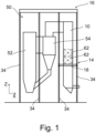
- a power boiler 50 in relation to which the presented solution may be applied comprises, at least, a furnace 52 and a flue gas duct 10 for conveying flue gases, the flue gas duct 10 including a vertical section in which flues gases flow downwards.
- heat exchangers in the flue gas duct 10 which may include preheaters, e.g. an economiser adapted to cool down the flue gases and preheat water fed to a water circulation system of the power boiler 50, and an air heater downstream of the economiser.
- the power boiler 50 further includes a support frame 16 for supporting the furnace 52 to the ground and a supporting beam arrangement 14 for supporting the flue gas duct to the support frame 16.
- the power boiler 50 is a steam boiler of CFB (circulating fluidized bed) or BFB (bubbling fluidized bed) design.
- the power boiler 50 may comprise further devices that are relevant for the design in question but are not shown in the figures.
- the power boiler 50 may additionally comprise a cyclone separator 54 connected to the furnace 52 for separating solid particles from flue gases coming from the furnace 52.
- the cyclone separator 54 may be supported to the support frame 16.
- the presented solution relates to a supporting beam arrangement 14 for supporting a flue gas duct 10 which is adapted to convey flue gases pass heat exchangers.
- the supporting beam arrangement 14 is adapted to support the flue gas duct 10 to a support frame 16 of the flue gas duct 10.
- the supporting beam arrangement 14 comprises two substantially horizontal first supporting beams 18, a substantially horizontal second supporting beam 20 defining two opposite ends 22, and an opening 24 in each first supporting beam 18, the opening 24 being for one of the ends 22 of the second supporting beam 20.
- the supporting beam arrangement 14 may, as shown in the example in Fig. 2 , comprise additional second supporting beams 20 and openings 24 in each first supporting beam 18 in such a way that the principles explained below apply.
- the first supporting beam 18 may be replaced with two successive, short first supporting beams 18 as shown in Fig. 6 and being separated by a pillar 34 to which the consecutive first supporting beams 18 are connected.
- the two substantially horizontal first supporting beams 18 are parallel and situated on two opposite sides of the flue gas duct 10.
- the first supporting beams 18 are separated by a distance from the flue gas duct 10 and the first supporting beams 18 include two opposite ends that are connected to the support frame 16.
- the two opposite ends 22 of the second supporting beam 20 are supported to the first supporting beams 18 and the second supporting beam 20 extends through the flue gas duct 10 in such a way that the second supporting beam 20 is exposed to flue gases.
- the flue gas duct 10 is supported to the second supporting beam 20.
- Each first supporting beam 18 comprises an opening 24, in which opening 24 one of the two opposite ends 22 of the second supporting beam 20 is placed to rest on the first supporting beam 18 in such a way that loads incurred by the weight of the flue gas duct 10 are transmitted to the first supporting beam 18.
- the first supporting beam 18 is an I-beam or a H-beam, including upper and lower flanges 26, 28 that are parallel, extend in a longitudinal direction of the beam, and are connected by a web 30 extending in the longitudinal direction, as shown in Fig. 3 on the left.
- the opening 24 may be formed to the web 30 of the beam, underneath the upper flange 26 and above the lower flange 28.
- the first supporting beam 18 is a box beam with one or more walls attached to each other and extending in the longitudinal direction.
- the box beam includes upper and lower walls 56 that are parallel, extend in a longitudinal direction of the beam and are connected by two or more side walls 58 extending in the longitudinal direction.
- the box beam may be fabricated by attaching two or more beams, e.g. I-beams, H-beams, and/or U-beams to each other in such a way that the upper and lower walls 56 are formed by the upper and lower flanges 26 and 28, respectively, and the side walls 58 are formed by the webs 30.
- the box beam may have a rectangular or square cross-section.
- the box beam provides a hollow structure with at least one hollow cell.
- the box beam provides at least one closed cell.
- the opening 24 may be formed to all side walls 58 or at least one of the side walls 58, underneath the upper wall 56 and above the lower wall 56.
- the opening 24 may go through the first supporting beam 18 in such a way that the opening 24 gives access from one side of the first supporting beam 18 to the other side of the first supporting beam 18. This is the case in particular for the I-beams and H-beams.
- the opening 24 may go through at least one side wall 58 of the first supporting beam 18 in such a way that the opening 24 gives access from one side of the first supporting beam 18 to the inside of the first supporting beam 18.
- the opening 24 may go through all the side walls 58 of the first supporting beam 18 in such a way that the opening 24 gives access from one side of the first supporting beam 18 to the other side of the first supporting beam 18. This is the case in particular for the box beams.
- the supporting beam arrangement 14 further comprises slide bearings 60 in the openings 24 as shown in Figs. 2 and 4 .
- Each end 22 of the second supporting beam 20 rests on one of the slide bearings 60 and the slide bearings 60 are supported to the first supporting beams 18.
- the slide bearings 60 allow the thermal expansion of the second supporting beam 20 to take place and movement of each end 22 of the second supporting beam 20 in a substantially horizontal direction, e.g. in the longitudinal direction of the second supporting beam 20, in relation to first supporting beam 18.
- each slide bearing 60 is in the opening 24 in a vertical direction between the first supporting beam 18 and one of the ends 22 of the second supporting beam 20.
- the first supporting beam 18 may have stiffeners to stiffen the first supporting beam 18 against deformations.
- the stiffeners may be plates or flanges attached to e.g. the web 30, the upper flange 26, the lower 28, the upper wall 56, the lower wall 56, and/or the side wall 58.
- plates or flanges are attached to the first supporting beam 18 to cover, shield or enclose the end 22 of the second supporting beam 20, and the slide bearing 60, placed in the opening 24.
- the support frame 16 comprises vertical pillars 34 by means of which the first supporting beams 18 are supported to the ground. Each end of the first supporting beams 18 is connected to one of the pillars 34. Thereby, loads incurred by the weight of the flue gas duct 10 are transmitted to the pillars 34 directly by the first supporting beams 18.
- the support frame 16 comprises vertical pillars 34 and two substantially horizontal primary supporting beams.
- the primary supporting beams are substantially parallel, and each primary supporting beam includes two opposite ends that are connected to the pillars 34 by means of which the primary supporting beams are supported to the ground.
- each end of the first supporting beams 18 is connected to one of the primary supporting beams.
- the primary supporting beams are substantially perpendicular to the first supporting beams 18.
- the first supporting beam 18 defines a substantially horizontal top surface 32, see Figs. 2 and 4 .
- the opening 24 and the end 22 of the second supporting beam 20 in the opening 24 are located underneath the top surface 32 which extends in a continuous manner in the longitudinal direction.
- the top surface 32 may be formed by the upper flange 26, or the upper wall 56, discussed above.
- the second supporting beam 20 includes a middle section 36 horizontally extending within the flue gas duct 10 and two end sections 38, each end section 38 horizontally extending outside the flue gas duct 10 between the flue gas duct 10 and one of the first supporting beams 18.
- the middle section 36 and either one or preferably both of the end sections 38 may define a stepped shape for the second supporting beam 20, See Fig. 4 .
- the middle section 36 may define a substantially horizontal top surface 42 and each end section 38 may define a substantially horizontal top surface 44.
- the second supporting beam 20 has the stepped shape in such a way that the top surfaces 44 of the end sections 38 are at a height lower than the top surface 42 of the middle section 36.
- the top surfaces 44 of the end sections 38 of the second supporting beam 20 are at the same height.
- the stepped shape enables placing additional supporting or reinforcing beams or bars above the end sections 38 of the second supporting beam 20 in a compact manner for providing structures with a reduced height.
- the middle section 36 defines a first beam height B1 and each end section 38 defines a second beam height B2.
- the second beam height B2 is smaller than the first beam height B1 and the second beam height B2 is at the most 90%, 80%, or 70%, or at the most 60% of the first beam height B1.
- the second supporting beam 20 may further include two outer end sections 40, each outer end section 40 including one of the ends 22 of the second supporting beam 20 and horizontally extending outside the flue gas duct 10 between the flue gas duct 10 and one of the first supporting beams 18.
- each outer end section 40 defines a third beam height B3.
- the third beam height B3 is smaller than the second beam height B2 and the third beam height B3 is at the most 90%, 80%, or 70%, or at the most 60% of the second beam height B2.
- the top surface 32 of the first supporting beam 18 is at a first height H1 and the top surface 44 of each end section 38 of the second supporting beam 20 is at a second height H2, the second height H2 being less than the first height H1.
- the difference in height enables placing additional supporting or reinforcing beams or bars above the end sections 38 of the second supporting beam 20 in a compact manner for proving structures with a reduced height.
- the top surface 42 of the middle section 36 in the second supporting beam 20 is at a third height H3, the second height H2 being less than the third height H3.
- the supporting beam arrangement 14 further comprises a substantially horizontal intermediate supporting beam 46 that is substantially parallel with the first supporting beams 18 and substantially perpendicular to the second supporting beam 20.
- the intermediate supporting beam 46 is supported to the support frame 16, e.g. to the pillars 34, either directly or via another supporting beam.
- the intermediate supporting beam 46 is in a vertical direction located above the top surface 44 of one of the end sections 38 in the second supporting beam 20.
- the supporting beam arrangement 14 further comprises substantially horizontal reinforcing bars 48 each having a first end connected to one of the first supporting beams 18 and an opposing second end connected to the intermediate supporting beam 46.
- the reinforcing bars 48 may be substantially perpendicular to the first supporting beams 18 and/or the reinforcing bars 48 extend at an oblique angle in relation to the first supporting beams 18.
- At least some of the reinforcing bars 48 are in a vertical direction located above the top surface 44 of the end sections 38 of the second supporting beam 20.
- the reinforcing bars 48 are additionally placed at a height lower than the top surfaces 32 of first supporting beams 18, see Figs 4 and 5 .
- the power boiler 50 in relation to which the presented solution may be applied comprises, as described above, the supporting beam arrangement 14, the flue gas duct 10 and the support frame 16, see Fig. 1 .
- the flue gas duct 10 comprises at least one heat exchanger 62 constituting e.g. an economiser and including a bank of tubes and adapted to transfer heat from the flue gases to medium flowing inside tubes of the bank of tubes.
- the flue gas duct 10 conveys flue gases downwards in a vertical direction.
- the heat exchanger 62 is supported to the flue gas duct 10 and, according to an example, additionally to the second supporting beam 20.
- the supporting beam arrangement 14 may be located below the heat exchanger 62, e.g. an economiser.
- the principles in the examples presented above in relation to the second supporting beam 20 apply to any additional supporting beam that is parallel with the above-mentioned second supporting beam 20 and constitutes an additional second supporting beam 20.
- the first supporting beams 18 comprises openings 24 for each second supporting beam 20 in a manner described above. According to an example, there are four second supporting beams 20.
- only one of the first supporting beams 18 may apply the principles in the examples presented above.
- only one end 22 of the second supporting beam 20 may apply the principles in the examples presented above. Therefore, the principles in the examples presented above may be applied on one side or, preferably, on both sides of the flue gas duct 10 to provide a compact structure.
- the terms “substantially vertical” and “substantially horizontal” may be replaced with the terms “vertical” and “horizontal”.
- the direction of the acceleration due to gravity is defined as the “vertical direction”, the “horizontal direction” defining directions perpendicular to the vertical direction.
- the orientations defined in this description see e.g. “substantially vertical”, “substantially horizontal”, “substantially perpendicular”, and “substantially parallel”, they also include orientations at angles in relation to absolute vertical, horizontal, perpendicular, and parallel directions, whereby the angles cover a range of angles considered reasonable when taking production tolerances and installation work into consideration, and without departing from the concept of the presented solution. According to an example, the range of angles covers angles between -10° and +10°, or between -5° and +5°.
Landscapes
- Engineering & Computer Science (AREA)
- Physics & Mathematics (AREA)
- Thermal Sciences (AREA)
- Mechanical Engineering (AREA)
- General Engineering & Computer Science (AREA)
- Chemical & Material Sciences (AREA)
- Combustion & Propulsion (AREA)
- Treating Waste Gases (AREA)
- Supports For Pipes And Cables (AREA)
- Incineration Of Waste (AREA)
Claims (12)
- Eine Stützbalkenanordnung, die zum Stützen eines Rauchgaskanals geeignet ist, wobei die Stützbalkenanordnung (14) Folgendes umfasst:- zwei im Wesentlichen horizontale erste Stützbalken (18), die im Wesentlichen parallel und auf zwei gegenüberliegenden Seiten des Rauchgaskanals (10) angeordnet sind, wobei die ersten Stützbalken (18) durch einen Abstand vom Rauchgaskanal (10) getrennt sind und die ersten Stützbalken (18) zwei gegenüberliegende Enden aufweisen, die mit einem Stützrahmen (16) des Rauchgaskanals (10) verbunden sind; und- im Wesentlichen horizontalen zweiten Stützbalken (20), der zwei gegenüberliegende Enden (22) definiert, die von den ersten Stützbalken (18) gestützt werden, wobei sich der zweite Stützbalken (20) durch den Rauchgaskanal (10) in einer solchen Weise erstreckt, dass der zweite Stützbalken (20) den Rauchgasen ausgesetzt ist, die der Rauchgaskanal zu befördern vermag, wobei der zweite Stützbalken (20) den Rauchgaskanal (10) stützt;- wobei mindestens einer oder jeder der ersten Stützbalken (18) eine Öffnung (24) aufweist, wobei in dieser Öffnung eines der beiden gegenüberliegenden Enden (22) des zweiten Stützbalkens (20) so auf dem ersten Stützbalken (18) aufliegt, dass durch das Gewicht des Rauchgaskanals (10) entstehende Lasten auf den ersten Stützbalken (18) übertragen werden;dadurch gekennzeichnet, dass:- der erste Stützbalken (18) eine im Wesentlichen horizontale obere Fläche (32) in einer ersten Höhe (H1) definiert; und- der zweite Stützbalken (20) zwei Endabschnitte (38) umfasst, wobei sich jeder Endabschnitt horizontal außerhalb des Rauchgaskanals (10) zwischen dem Rauchgaskanal und einem der ersten Stützbalken (18) erstreckt, wobei mindestens einer oder jeder der Endabschnitte (38) eine im Wesentlichen horizontale obere Fläche (44) definiert, die sich in einer zweiten Höhe (H2) befindet, wobei die zweite Höhe (H2) geringer ist als die erste Höhe (H1);wobei die Stützbalkenanordnung (14) ferner Folgendes umfasst:- einen im Wesentlichen horizontalen Zwischenstützbalken (46), der im Wesentlichen parallel zu den ersten Stützbalken (18) und im Wesentlichen senkrecht zu dem zweiten Stützbalken (20) verläuft, wobei der Zwischenstützbalken (46) von dem Tragrahmen (16) getragen wird, wobei der Zwischenstützbalken (46) in einer vertikalen Richtung oberhalb der oberen Fläche (44) eines der Endabschnitte (38) angeordnet ist; und- im Wesentlichen horizontale Verstärkungsstäbe (48), von denen jeder ein erstes Ende hat, das mit einem der ersten Stützbalken (18) verbunden ist, und ein gegenüberliegendes zweites Ende, das mit dem Zwischenstützbalken (46) verbunden ist, wobei (i) die Verstärkungsstäbe (48) im Wesentlichen senkrecht zu den ersten Stützbalken (18) verlaufen oder (ii) die Verstärkungsstäbe sich in einem schrägen Winkel in Bezug auf die ersten Stützbalken (18) erstrecken, und wobei die Verstärkungsstäbe (48) in einer vertikalen Richtung oberhalb der oberen Oberfläche (44) eines der Endabschnitte (38) angeordnet sind.
- Die Stützbalkenanordnung nach Anspruch 1, wobei der zweite Stützbalken (20) einen mittleren Abschnitt (36) aufweist, der sich horizontal innerhalb des Rauchgaskanals (10) erstreckt, wobei der mittlere Abschnitt (36) eine im Wesentlichen horizontale obere Fläche (42) definiert, die sich in einer dritten Höhe (H3) befindet, und wobei die zweite Höhe (H2) geringer ist als die dritte Höhe (H3).
- Die Stützbalkenanordnung nach Anspruch 1 oder 2, wobei- (i) die Verstärkungsstäbe (48) in einer Höhe angeordnet sind, die niedriger ist als die obere Fläche (32) des ersten Stützbalkens (18), oder- (ii) der Zwischenstützbalken (46) in einer Höhe angeordnet ist, die niedriger ist als die obere Fläche (32) des ersten Stützbalkens (18).
- Die Stützbalkenanordnung nach einem der Ansprüche 1 bis 3, wobei der erste Stützbalken (18)- (i) ein I-Balken oder (ii) ein H-Balken ist, der obere und untere Flansche (26, 28) aufweist, die parallel zueinander verlaufen, sich in einer Längsrichtung des Balkens erstrecken und durch einen sich in der Längsrichtung erstreckenden Steg (30) verbunden sind, wobei die Öffnung (24) an dem Steg des Balkens unterhalb des oberen Flansches und oberhalb des unteren Flansches ausgebildet ist, oder- (iii) einen Kastenbalken mit einer oberen und einer unteren Wand (56), die parallel zueinander verlaufen, sich in einer Längsrichtung des Balkens erstrecken und durch zwei oder mehr in Längsrichtung verlaufende Seitenwände (58) verbunden sind, wobei die Öffnung (24) an mindestens einer der Seitenwände oder allen Seitenwänden unterhalb der oberen Wand und oberhalb der unteren Wand ausgebildet ist.
- Die Stützbalkenanordnung nach einem der Ansprüche 1 bis 4, wobei sich die Öffnung (24) und das Ende (22) des zweiten Stützbalkens (20) in der Öffnung (24) unterhalb der oberen Fläche (32) befinden, die sich durchgehend in Längsrichtung erstreckt.
- Die Stützbalkenanordnung nach einem der Ansprüche 1 bis 5, ferner mit einem Gleitlager (60) in der Öffnung (24), wobei mindestens eines oder jedes der Enden (22) des zweiten Stützbalkens (20) auf einem der Gleitlager (60) aufliegt, wobei das Gleitlager von dem ersten Stützbalken (18) getragen wird.
- Die Stützbalkenanordnung nach einem der Ansprüche 1 bis 6, wobei der Stützrahmen (16) vertikale Säulen (34) umfasst und jedes Ende des ersten Stützbalkens (18) mit einer der Säulen (34) verbunden ist, über die der erste Stützbalken (18) auf dem Boden abgestützt ist.
- Die Stützbalkenanordnung nach einem der Ansprüche 1 bis 6,- wobei der Stützrahmen (16) vertikale Säulen (34) und zwei im Wesentlichen horizontale primäre Stützbalken umfasst, die im Wesentlichen parallel sind und zwei gegenüberliegende Enden definieren, die mit den Säulen (34) verbunden sind, mittels derer die primären Stützbalken auf dem Boden abgestützt sind; und- wobei jedes Ende des ersten Stützbalkens (18) mit einem der primären Stützbalken verbunden ist, wobei die primären Stützbalken im Wesentlichen senkrecht zu dem ersten Stützbalken (18) stehen.
- Die Stützbalkenanordnung nach Anspruch 1,- wobei der zweite Stützbalken (20) einen mittleren Abschnitt (36) aufweist, der sich horizontal innerhalb des Rauchgaskanals (10) erstreckt, wobei der mittlere Abschnitt (36) eine im Wesentlichen horizontale obere Fläche (42) definiert, wobei jeder Endabschnitt (38) des zweiten Stützbalkens (20) eine im Wesentlichen horizontale obere Fläche (44) definiert; und- wobei der mittlere Abschnitt (36) und die Endabschnitte (38) eine gestufte Form in der Weise definieren, dass mindestens eine oder jede der oberen Flächen (44) der Endabschnitte (38) auf einer niedrigeren Höhe als die obere Fläche (42) des mittleren Abschnitts (36) liegt.
- Die Stützbalkenanordnung nach Anspruch 1,- wobei der zweite Stützbalken (20) einen mittleren Abschnitt (36) aufweist, der sich horizontal innerhalb des Rauchgaskanals (10) erstreckt und eine erste Balkenhöhe (B1) definiert, wobei mindestens einer oder jeder der Endabschnitte (38) des zweiten Stützbalkens (20) eine zweite Balkenhöhe (B2) definiert; und- wobei die zweite Balkenhöhe (B2) kleiner als die erste Balkenhöhe (B1) ist und die zweite Balkenhöhe (B2) höchstens 90% der ersten Balkenhöhe (B1) beträgt.
- Die Stützbalkenanordnung nach Anspruch 10,- wobei der zweite Stützbalken (20) ferner zwei äußere Endabschnitte (40) umfasst, wobei jeder äußere Endabschnitt eines der Enden des zweiten Stützbalkens (20) umfasst und sich horizontal außerhalb des Rauchgaskanals (10) zwischen dem Rauchgaskanal und einem der ersten Stützbalken (18) erstreckt, wobei mindestens einer oder jeder der äußeren Endabschnitte (40) eine dritte Balkenhöhe (B3) definiert; und- wobei die dritte Balkenhöhe (B3) kleiner als die zweite Balkenhöhe (B2) ist und die dritte Balkenhöhe (B3) höchstens 90% der zweiten Balkenhöhe (B2) beträgt.
- Ein Hochleistungskessel (50) mit dem Rauchgaskanal (10), dem Stützrahmen (16) und der Stützbalkenanordnung (14) nach einem der Ansprüche 1 bis 11.
Priority Applications (1)
| Application Number | Priority Date | Filing Date | Title |
|---|---|---|---|
| HRP20241100TT HRP20241100T1 (hr) | 2019-06-10 | 2020-04-02 | Aranžman potporne grede za podupiranje kanala dimnih plinova |
Applications Claiming Priority (1)
| Application Number | Priority Date | Filing Date | Title |
|---|---|---|---|
| FI20195490A FI128596B (en) | 2019-06-10 | 2019-06-10 | A support beam arrangement for supporting the flue gas duct, and a power boiler including it |
Publications (2)
| Publication Number | Publication Date |
|---|---|
| EP3751195A1 EP3751195A1 (de) | 2020-12-16 |
| EP3751195B1 true EP3751195B1 (de) | 2024-05-29 |
Family
ID=70391059
Family Applications (1)
| Application Number | Title | Priority Date | Filing Date |
|---|---|---|---|
| EP20397504.0A Active EP3751195B1 (de) | 2019-06-10 | 2020-04-02 | Stützbalkenanordnung zum stützen einer rauchgasleitung |
Country Status (8)
| Country | Link |
|---|---|
| US (1) | US11162675B2 (de) |
| EP (1) | EP3751195B1 (de) |
| KR (1) | KR102871278B1 (de) |
| CN (1) | CN112066358B (de) |
| CA (1) | CA3077722A1 (de) |
| FI (1) | FI128596B (de) |
| HR (1) | HRP20241100T1 (de) |
| PL (1) | PL3751195T3 (de) |
Families Citing this family (1)
| Publication number | Priority date | Publication date | Assignee | Title |
|---|---|---|---|---|
| CN112797428A (zh) * | 2021-01-15 | 2021-05-14 | 福建省榕圣市政工程股份有限公司 | 预制式烟道管连接组件 |
Family Cites Families (16)
| Publication number | Priority date | Publication date | Assignee | Title |
|---|---|---|---|---|
| US1877391A (en) * | 1932-04-18 | 1932-09-13 | Alco Products Inc | Tube hanger |
| US2987052A (en) * | 1958-09-29 | 1961-06-06 | Comb Engineers Inc | Wall construction for pressurized furnace |
| CH506751A (de) * | 1969-04-17 | 1971-04-30 | Sulzer Ag | Dampferzeuger mit aus vertikalen, verschweissten Rohren gebildeter Wandberohrung |
| US3842904A (en) * | 1972-06-15 | 1974-10-22 | Aronetics Inc | Heat exchanger |
| US4286549A (en) * | 1979-12-03 | 1981-09-01 | Foster Wheeler Energy Corporation | Steam generator support system |
| US4685426A (en) | 1986-05-05 | 1987-08-11 | The Babcock & Wilcox Company | Modular exhaust gas steam generator with common boiler casing |
| SE466417B (sv) * | 1990-06-15 | 1992-02-10 | Abb Carbon Ab | Vraengningshinder foer spantbalkar i ramverk foer vertikalt monterade baeddkaerl |
| US5339891A (en) * | 1993-07-15 | 1994-08-23 | The Babcock & Wilcox Company | Modular arrangement for heat exchanger units |
| JPH08285207A (ja) | 1995-04-19 | 1996-11-01 | Mitsubishi Heavy Ind Ltd | 竪流れ型ボイラの支持装置 |
| US6039008A (en) * | 1999-02-01 | 2000-03-21 | Combustion Engineering, Inc. | Steam generator having an improved structural support system |
| FI124485B (fi) * | 2007-05-08 | 2014-09-30 | Valmet Power Oy | Kattilalaitos, tukirakenne ja menetelmä kattilalaitoksen soodakattilan seinien tukemiseksi |
| EP2026000A1 (de) * | 2007-08-10 | 2009-02-18 | Siemens Aktiengesellschaft | Dampferzeuger |
| EP2325559B1 (de) * | 2009-11-19 | 2016-12-28 | NEM Power-Systems, Niederlassung Deutschland der NEM B.V. Niederlande | Anordnung zur Beeinflussung einer Abgasströmung |
| FI20145240L (fi) | 2014-03-17 | 2015-09-18 | Valmet Technologies Oy | Polttokattila |
| FI126039B (en) * | 2014-06-03 | 2016-06-15 | Amec Foster Wheeler En Oy | Swivel bed boiler with a support structure for a particle separator |
| JP2020134104A (ja) * | 2019-02-26 | 2020-08-31 | 三菱電機株式会社 | 浴室換気乾燥暖房機 |
-
2019
- 2019-06-10 FI FI20195490A patent/FI128596B/en active IP Right Grant
-
2020
- 2020-04-01 CA CA3077722A patent/CA3077722A1/en active Pending
- 2020-04-02 EP EP20397504.0A patent/EP3751195B1/de active Active
- 2020-04-02 PL PL20397504.0T patent/PL3751195T3/pl unknown
- 2020-04-02 HR HRP20241100TT patent/HRP20241100T1/hr unknown
- 2020-04-27 US US16/859,240 patent/US11162675B2/en active Active
- 2020-06-05 KR KR1020200068466A patent/KR102871278B1/ko active Active
- 2020-06-10 CN CN202010522632.XA patent/CN112066358B/zh active Active
Also Published As
| Publication number | Publication date |
|---|---|
| HRP20241100T1 (hr) | 2024-11-08 |
| CN112066358B (zh) | 2023-11-28 |
| KR20200141940A (ko) | 2020-12-21 |
| US11162675B2 (en) | 2021-11-02 |
| US20200386399A1 (en) | 2020-12-10 |
| KR102871278B1 (ko) | 2025-10-14 |
| FI128596B (en) | 2020-08-31 |
| CA3077722A1 (en) | 2020-12-10 |
| PL3751195T3 (pl) | 2024-10-28 |
| CN112066358A (zh) | 2020-12-11 |
| FI20195490A1 (en) | 2020-08-31 |
| EP3751195A1 (de) | 2020-12-16 |
Similar Documents
| Publication | Publication Date | Title |
|---|---|---|
| US5117770A (en) | Combustion unit | |
| JPH0313482B2 (de) | ||
| EP3751195B1 (de) | Stützbalkenanordnung zum stützen einer rauchgasleitung | |
| EP3017248B1 (de) | Wirbelschichtkessel mit stützkonstruktion für partikelabscheider | |
| US7509928B2 (en) | Suspended steam boiler | |
| KR20080093985A (ko) | 파워 보일러의 벽을 지지하기 위한 방법 및 장치 | |
| US3208436A (en) | Furnace wall support and expansion apparatus | |
| EP3982043B1 (de) | Mittelgestütze kesselkonstruktion | |
| EP3472513B1 (de) | Bodengestützter kessel | |
| US4368695A (en) | Supporting the weight of a structure in a hot environment | |
| FI121638B (fi) | Leijupetireaktori | |
| CN101696798B (zh) | 带有异型分隔墙的紧凑型循环流化床锅炉 | |
| EP3311073B1 (de) | Vorrichtung mit zirkulierendem wirbelbett | |
| RU2692439C1 (ru) | Паровой котёл | |
| EP3704411B1 (de) | Boilersystem mit stützkonstruktion | |
| EP0065046B1 (de) | Abstützen der Last eines Bauteiles in einer heissen Umgebung | |
| EP4241035B1 (de) | Halteelement zum halten von wärmeübertragerrohren | |
| CA1178497A (en) | Supporting the weight of a structure in a hot environment | |
| CN103168199A (zh) | 用于锅炉装置的炉壁结构 | |
| KR20180040152A (ko) | 순환 유동상 퍼니스 | |
| EP0717826B1 (de) | Dampferzeuger | |
| JP2023532168A (ja) | 火力蒸気発生器における垂直煙道ガス通路の側壁を支持する装置および方法 | |
| WO1999028675A1 (en) | A refuse incineration boiler |
Legal Events
| Date | Code | Title | Description |
|---|---|---|---|
| REG | Reference to a national code |
Ref country code: HR Ref legal event code: TUEP Ref document number: P20241100T Country of ref document: HR |
|
| PUAI | Public reference made under article 153(3) epc to a published international application that has entered the european phase |
Free format text: ORIGINAL CODE: 0009012 |
|
| STAA | Information on the status of an ep patent application or granted ep patent |
Free format text: STATUS: THE APPLICATION HAS BEEN PUBLISHED |
|
| AK | Designated contracting states |
Kind code of ref document: A1 Designated state(s): AL AT BE BG CH CY CZ DE DK EE ES FI FR GB GR HR HU IE IS IT LI LT LU LV MC MK MT NL NO PL PT RO RS SE SI SK SM TR |
|
| AX | Request for extension of the european patent |
Extension state: BA ME |
|
| STAA | Information on the status of an ep patent application or granted ep patent |
Free format text: STATUS: REQUEST FOR EXAMINATION WAS MADE |
|
| 17P | Request for examination filed |
Effective date: 20210615 |
|
| RBV | Designated contracting states (corrected) |
Designated state(s): AL AT BE BG CH CY CZ DE DK EE ES FI FR GB GR HR HU IE IS IT LI LT LU LV MC MK MT NL NO PL PT RO RS SE SI SK SM TR |
|
| STAA | Information on the status of an ep patent application or granted ep patent |
Free format text: STATUS: EXAMINATION IS IN PROGRESS |
|
| 17Q | First examination report despatched |
Effective date: 20230118 |
|
| P01 | Opt-out of the competence of the unified patent court (upc) registered |
Effective date: 20230602 |
|
| GRAP | Despatch of communication of intention to grant a patent |
Free format text: ORIGINAL CODE: EPIDOSNIGR1 |
|
| STAA | Information on the status of an ep patent application or granted ep patent |
Free format text: STATUS: GRANT OF PATENT IS INTENDED |
|
| INTG | Intention to grant announced |
Effective date: 20240102 |
|
| GRAS | Grant fee paid |
Free format text: ORIGINAL CODE: EPIDOSNIGR3 |
|
| GRAA | (expected) grant |
Free format text: ORIGINAL CODE: 0009210 |
|
| STAA | Information on the status of an ep patent application or granted ep patent |
Free format text: STATUS: THE PATENT HAS BEEN GRANTED |
|
| AK | Designated contracting states |
Kind code of ref document: B1 Designated state(s): AL AT BE BG CH CY CZ DE DK EE ES FI FR GB GR HR HU IE IS IT LI LT LU LV MC MK MT NL NO PL PT RO RS SE SI SK SM TR |
|
| REG | Reference to a national code |
Ref country code: CH Ref legal event code: EP |
|
| REG | Reference to a national code |
Ref country code: IE Ref legal event code: FG4D |
|
| REG | Reference to a national code |
Ref country code: DE Ref legal event code: R096 Ref document number: 602020031600 Country of ref document: DE |
|
| REG | Reference to a national code |
Ref country code: SE Ref legal event code: TRGR |
|
| REG | Reference to a national code |
Ref country code: LT Ref legal event code: MG9D |
|
| REG | Reference to a national code |
Ref country code: NL Ref legal event code: MP Effective date: 20240529 |
|
| PG25 | Lapsed in a contracting state [announced via postgrant information from national office to epo] |
Ref country code: IS Free format text: LAPSE BECAUSE OF FAILURE TO SUBMIT A TRANSLATION OF THE DESCRIPTION OR TO PAY THE FEE WITHIN THE PRESCRIBED TIME-LIMIT Effective date: 20240929 |
|
| PG25 | Lapsed in a contracting state [announced via postgrant information from national office to epo] |
Ref country code: BG Free format text: LAPSE BECAUSE OF FAILURE TO SUBMIT A TRANSLATION OF THE DESCRIPTION OR TO PAY THE FEE WITHIN THE PRESCRIBED TIME-LIMIT Effective date: 20240529 |
|
| PG25 | Lapsed in a contracting state [announced via postgrant information from national office to epo] |
Ref country code: FI Free format text: LAPSE BECAUSE OF FAILURE TO SUBMIT A TRANSLATION OF THE DESCRIPTION OR TO PAY THE FEE WITHIN THE PRESCRIBED TIME-LIMIT Effective date: 20240529 |
|
| PG25 | Lapsed in a contracting state [announced via postgrant information from national office to epo] |
Ref country code: GR Free format text: LAPSE BECAUSE OF FAILURE TO SUBMIT A TRANSLATION OF THE DESCRIPTION OR TO PAY THE FEE WITHIN THE PRESCRIBED TIME-LIMIT Effective date: 20240830 |
|
| PG25 | Lapsed in a contracting state [announced via postgrant information from national office to epo] |
Ref country code: ES Free format text: LAPSE BECAUSE OF FAILURE TO SUBMIT A TRANSLATION OF THE DESCRIPTION OR TO PAY THE FEE WITHIN THE PRESCRIBED TIME-LIMIT Effective date: 20240529 |
|
| PG25 | Lapsed in a contracting state [announced via postgrant information from national office to epo] |
Ref country code: LV Free format text: LAPSE BECAUSE OF FAILURE TO SUBMIT A TRANSLATION OF THE DESCRIPTION OR TO PAY THE FEE WITHIN THE PRESCRIBED TIME-LIMIT Effective date: 20240529 |
|
| PG25 | Lapsed in a contracting state [announced via postgrant information from national office to epo] |
Ref country code: NO Free format text: LAPSE BECAUSE OF FAILURE TO SUBMIT A TRANSLATION OF THE DESCRIPTION OR TO PAY THE FEE WITHIN THE PRESCRIBED TIME-LIMIT Effective date: 20240829 Ref country code: LV Free format text: LAPSE BECAUSE OF FAILURE TO SUBMIT A TRANSLATION OF THE DESCRIPTION OR TO PAY THE FEE WITHIN THE PRESCRIBED TIME-LIMIT Effective date: 20240529 Ref country code: IS Free format text: LAPSE BECAUSE OF FAILURE TO SUBMIT A TRANSLATION OF THE DESCRIPTION OR TO PAY THE FEE WITHIN THE PRESCRIBED TIME-LIMIT Effective date: 20240929 Ref country code: GR Free format text: LAPSE BECAUSE OF FAILURE TO SUBMIT A TRANSLATION OF THE DESCRIPTION OR TO PAY THE FEE WITHIN THE PRESCRIBED TIME-LIMIT Effective date: 20240830 Ref country code: FI Free format text: LAPSE BECAUSE OF FAILURE TO SUBMIT A TRANSLATION OF THE DESCRIPTION OR TO PAY THE FEE WITHIN THE PRESCRIBED TIME-LIMIT Effective date: 20240529 Ref country code: ES Free format text: LAPSE BECAUSE OF FAILURE TO SUBMIT A TRANSLATION OF THE DESCRIPTION OR TO PAY THE FEE WITHIN THE PRESCRIBED TIME-LIMIT Effective date: 20240529 Ref country code: BG Free format text: LAPSE BECAUSE OF FAILURE TO SUBMIT A TRANSLATION OF THE DESCRIPTION OR TO PAY THE FEE WITHIN THE PRESCRIBED TIME-LIMIT Effective date: 20240529 Ref country code: RS Free format text: LAPSE BECAUSE OF FAILURE TO SUBMIT A TRANSLATION OF THE DESCRIPTION OR TO PAY THE FEE WITHIN THE PRESCRIBED TIME-LIMIT Effective date: 20240829 |
|
| REG | Reference to a national code |
Ref country code: HR Ref legal event code: T1PR Ref document number: P20241100 Country of ref document: HR |
|
| PG25 | Lapsed in a contracting state [announced via postgrant information from national office to epo] |
Ref country code: NL Free format text: LAPSE BECAUSE OF FAILURE TO SUBMIT A TRANSLATION OF THE DESCRIPTION OR TO PAY THE FEE WITHIN THE PRESCRIBED TIME-LIMIT Effective date: 20240529 |
|
| REG | Reference to a national code |
Ref country code: AT Ref legal event code: UEP Ref document number: 1690940 Country of ref document: AT Kind code of ref document: T Effective date: 20240529 |
|
| PG25 | Lapsed in a contracting state [announced via postgrant information from national office to epo] |
Ref country code: NL Free format text: LAPSE BECAUSE OF FAILURE TO SUBMIT A TRANSLATION OF THE DESCRIPTION OR TO PAY THE FEE WITHIN THE PRESCRIBED TIME-LIMIT Effective date: 20240529 |
|
| PG25 | Lapsed in a contracting state [announced via postgrant information from national office to epo] |
Ref country code: DK Free format text: LAPSE BECAUSE OF FAILURE TO SUBMIT A TRANSLATION OF THE DESCRIPTION OR TO PAY THE FEE WITHIN THE PRESCRIBED TIME-LIMIT Effective date: 20240529 |
|
| PG25 | Lapsed in a contracting state [announced via postgrant information from national office to epo] |
Ref country code: EE Free format text: LAPSE BECAUSE OF FAILURE TO SUBMIT A TRANSLATION OF THE DESCRIPTION OR TO PAY THE FEE WITHIN THE PRESCRIBED TIME-LIMIT Effective date: 20240529 |
|
| PG25 | Lapsed in a contracting state [announced via postgrant information from national office to epo] |
Ref country code: SK Free format text: LAPSE BECAUSE OF FAILURE TO SUBMIT A TRANSLATION OF THE DESCRIPTION OR TO PAY THE FEE WITHIN THE PRESCRIBED TIME-LIMIT Effective date: 20240529 Ref country code: RO Free format text: LAPSE BECAUSE OF FAILURE TO SUBMIT A TRANSLATION OF THE DESCRIPTION OR TO PAY THE FEE WITHIN THE PRESCRIBED TIME-LIMIT Effective date: 20240529 |
|
| PG25 | Lapsed in a contracting state [announced via postgrant information from national office to epo] |
Ref country code: SM Free format text: LAPSE BECAUSE OF FAILURE TO SUBMIT A TRANSLATION OF THE DESCRIPTION OR TO PAY THE FEE WITHIN THE PRESCRIBED TIME-LIMIT Effective date: 20240529 |
|
| PG25 | Lapsed in a contracting state [announced via postgrant information from national office to epo] |
Ref country code: SM Free format text: LAPSE BECAUSE OF FAILURE TO SUBMIT A TRANSLATION OF THE DESCRIPTION OR TO PAY THE FEE WITHIN THE PRESCRIBED TIME-LIMIT Effective date: 20240529 Ref country code: SK Free format text: LAPSE BECAUSE OF FAILURE TO SUBMIT A TRANSLATION OF THE DESCRIPTION OR TO PAY THE FEE WITHIN THE PRESCRIBED TIME-LIMIT Effective date: 20240529 Ref country code: RO Free format text: LAPSE BECAUSE OF FAILURE TO SUBMIT A TRANSLATION OF THE DESCRIPTION OR TO PAY THE FEE WITHIN THE PRESCRIBED TIME-LIMIT Effective date: 20240529 Ref country code: EE Free format text: LAPSE BECAUSE OF FAILURE TO SUBMIT A TRANSLATION OF THE DESCRIPTION OR TO PAY THE FEE WITHIN THE PRESCRIBED TIME-LIMIT Effective date: 20240529 Ref country code: DK Free format text: LAPSE BECAUSE OF FAILURE TO SUBMIT A TRANSLATION OF THE DESCRIPTION OR TO PAY THE FEE WITHIN THE PRESCRIBED TIME-LIMIT Effective date: 20240529 |
|
| PG25 | Lapsed in a contracting state [announced via postgrant information from national office to epo] |
Ref country code: IT Free format text: LAPSE BECAUSE OF FAILURE TO SUBMIT A TRANSLATION OF THE DESCRIPTION OR TO PAY THE FEE WITHIN THE PRESCRIBED TIME-LIMIT Effective date: 20240529 |
|
| REG | Reference to a national code |
Ref country code: DE Ref legal event code: R097 Ref document number: 602020031600 Country of ref document: DE |
|
| PLBE | No opposition filed within time limit |
Free format text: ORIGINAL CODE: 0009261 |
|
| STAA | Information on the status of an ep patent application or granted ep patent |
Free format text: STATUS: NO OPPOSITION FILED WITHIN TIME LIMIT |
|
| PGFP | Annual fee paid to national office [announced via postgrant information from national office to epo] |
Ref country code: HR Payment date: 20250320 Year of fee payment: 6 |
|
| REG | Reference to a national code |
Ref country code: HR Ref legal event code: ODRP Ref document number: P20241100 Country of ref document: HR Payment date: 20250320 Year of fee payment: 6 |
|
| PG25 | Lapsed in a contracting state [announced via postgrant information from national office to epo] |
Ref country code: SI Free format text: LAPSE BECAUSE OF FAILURE TO SUBMIT A TRANSLATION OF THE DESCRIPTION OR TO PAY THE FEE WITHIN THE PRESCRIBED TIME-LIMIT Effective date: 20240529 |
|
| PGFP | Annual fee paid to national office [announced via postgrant information from national office to epo] |
Ref country code: PL Payment date: 20250323 Year of fee payment: 6 Ref country code: CZ Payment date: 20250326 Year of fee payment: 6 |
|
| 26N | No opposition filed |
Effective date: 20250303 |
|
| PGFP | Annual fee paid to national office [announced via postgrant information from national office to epo] |
Ref country code: DE Payment date: 20250422 Year of fee payment: 6 |
|
| PGFP | Annual fee paid to national office [announced via postgrant information from national office to epo] |
Ref country code: GB Payment date: 20250423 Year of fee payment: 6 |
|
| PGFP | Annual fee paid to national office [announced via postgrant information from national office to epo] |
Ref country code: BE Payment date: 20250418 Year of fee payment: 6 |
|
| PGFP | Annual fee paid to national office [announced via postgrant information from national office to epo] |
Ref country code: FR Payment date: 20250425 Year of fee payment: 6 |
|
| PGFP | Annual fee paid to national office [announced via postgrant information from national office to epo] |
Ref country code: AT Payment date: 20250423 Year of fee payment: 6 |
|
| PGFP | Annual fee paid to national office [announced via postgrant information from national office to epo] |
Ref country code: SE Payment date: 20250429 Year of fee payment: 6 |
|
| REG | Reference to a national code |
Ref country code: CH Ref legal event code: H13 Free format text: ST27 STATUS EVENT CODE: U-0-0-H10-H13 (AS PROVIDED BY THE NATIONAL OFFICE) Effective date: 20251125 |
|
| PG25 | Lapsed in a contracting state [announced via postgrant information from national office to epo] |
Ref country code: LU Free format text: LAPSE BECAUSE OF NON-PAYMENT OF DUE FEES Effective date: 20250402 |
|
| PG25 | Lapsed in a contracting state [announced via postgrant information from national office to epo] |
Ref country code: MC Free format text: LAPSE BECAUSE OF FAILURE TO SUBMIT A TRANSLATION OF THE DESCRIPTION OR TO PAY THE FEE WITHIN THE PRESCRIBED TIME-LIMIT Effective date: 20240529 |
|
| PG25 | Lapsed in a contracting state [announced via postgrant information from national office to epo] |
Ref country code: CH Free format text: LAPSE BECAUSE OF NON-PAYMENT OF DUE FEES Effective date: 20250430 |