EP3749409B1 - Vorrichtung zur gewebestimulation mittels frequenzabtastung von elektrischen und magnetischen feldern - Google Patents
Vorrichtung zur gewebestimulation mittels frequenzabtastung von elektrischen und magnetischen feldern Download PDFInfo
- Publication number
- EP3749409B1 EP3749409B1 EP19752004.2A EP19752004A EP3749409B1 EP 3749409 B1 EP3749409 B1 EP 3749409B1 EP 19752004 A EP19752004 A EP 19752004A EP 3749409 B1 EP3749409 B1 EP 3749409B1
- Authority
- EP
- European Patent Office
- Prior art keywords
- tissue
- stimulation
- frequency
- stage
- transducers
- Prior art date
- Legal status (The legal status is an assumption and is not a legal conclusion. Google has not performed a legal analysis and makes no representation as to the accuracy of the status listed.)
- Active
Links
Images


Classifications
-
- A—HUMAN NECESSITIES
- A61—MEDICAL OR VETERINARY SCIENCE; HYGIENE
- A61N—ELECTROTHERAPY; MAGNETOTHERAPY; RADIATION THERAPY; ULTRASOUND THERAPY
- A61N1/00—Electrotherapy; Circuits therefor
- A61N1/18—Applying electric currents by contact electrodes
- A61N1/32—Applying electric currents by contact electrodes alternating or intermittent currents
- A61N1/36—Applying electric currents by contact electrodes alternating or intermittent currents for stimulation
- A61N1/36014—External stimulators, e.g. with patch electrodes
- A61N1/3603—Control systems
- A61N1/36034—Control systems specified by the stimulation parameters
-
- A—HUMAN NECESSITIES
- A61—MEDICAL OR VETERINARY SCIENCE; HYGIENE
- A61N—ELECTROTHERAPY; MAGNETOTHERAPY; RADIATION THERAPY; ULTRASOUND THERAPY
- A61N1/00—Electrotherapy; Circuits therefor
-
- A—HUMAN NECESSITIES
- A61—MEDICAL OR VETERINARY SCIENCE; HYGIENE
- A61B—DIAGNOSIS; SURGERY; IDENTIFICATION
- A61B5/00—Measuring for diagnostic purposes; Identification of persons
- A61B5/05—Detecting, measuring or recording for diagnosis by means of electric currents or magnetic fields; Measuring using microwaves or radio waves
- A61B5/0507—Detecting, measuring or recording for diagnosis by means of electric currents or magnetic fields; Measuring using microwaves or radio waves using microwaves or terahertz waves
-
- A—HUMAN NECESSITIES
- A61—MEDICAL OR VETERINARY SCIENCE; HYGIENE
- A61B—DIAGNOSIS; SURGERY; IDENTIFICATION
- A61B5/00—Measuring for diagnostic purposes; Identification of persons
- A61B5/05—Detecting, measuring or recording for diagnosis by means of electric currents or magnetic fields; Measuring using microwaves or radio waves
- A61B5/053—Measuring electrical impedance or conductance of a portion of the body
-
- A—HUMAN NECESSITIES
- A61—MEDICAL OR VETERINARY SCIENCE; HYGIENE
- A61N—ELECTROTHERAPY; MAGNETOTHERAPY; RADIATION THERAPY; ULTRASOUND THERAPY
- A61N1/00—Electrotherapy; Circuits therefor
- A61N1/02—Details
- A61N1/04—Electrodes
-
- A—HUMAN NECESSITIES
- A61—MEDICAL OR VETERINARY SCIENCE; HYGIENE
- A61N—ELECTROTHERAPY; MAGNETOTHERAPY; RADIATION THERAPY; ULTRASOUND THERAPY
- A61N1/00—Electrotherapy; Circuits therefor
- A61N1/02—Details
- A61N1/04—Electrodes
- A61N1/06—Electrodes for high-frequency therapy
-
- A—HUMAN NECESSITIES
- A61—MEDICAL OR VETERINARY SCIENCE; HYGIENE
- A61N—ELECTROTHERAPY; MAGNETOTHERAPY; RADIATION THERAPY; ULTRASOUND THERAPY
- A61N1/00—Electrotherapy; Circuits therefor
- A61N1/02—Details
- A61N1/08—Arrangements or circuits for monitoring, protecting, controlling or indicating
-
- A—HUMAN NECESSITIES
- A61—MEDICAL OR VETERINARY SCIENCE; HYGIENE
- A61N—ELECTROTHERAPY; MAGNETOTHERAPY; RADIATION THERAPY; ULTRASOUND THERAPY
- A61N1/00—Electrotherapy; Circuits therefor
- A61N1/18—Applying electric currents by contact electrodes
- A61N1/32—Applying electric currents by contact electrodes alternating or intermittent currents
- A61N1/36—Applying electric currents by contact electrodes alternating or intermittent currents for stimulation
- A61N1/36002—Cancer treatment, e.g. tumour
-
- A—HUMAN NECESSITIES
- A61—MEDICAL OR VETERINARY SCIENCE; HYGIENE
- A61N—ELECTROTHERAPY; MAGNETOTHERAPY; RADIATION THERAPY; ULTRASOUND THERAPY
- A61N1/00—Electrotherapy; Circuits therefor
- A61N1/18—Applying electric currents by contact electrodes
- A61N1/32—Applying electric currents by contact electrodes alternating or intermittent currents
- A61N1/36—Applying electric currents by contact electrodes alternating or intermittent currents for stimulation
- A61N1/36014—External stimulators, e.g. with patch electrodes
- A61N1/3603—Control systems
- A61N1/36031—Control systems using physiological parameters for adjustment
-
- A—HUMAN NECESSITIES
- A61—MEDICAL OR VETERINARY SCIENCE; HYGIENE
- A61N—ELECTROTHERAPY; MAGNETOTHERAPY; RADIATION THERAPY; ULTRASOUND THERAPY
- A61N1/00—Electrotherapy; Circuits therefor
- A61N1/40—Applying electric fields by inductive or capacitive coupling ; Applying radio-frequency signals
-
- A—HUMAN NECESSITIES
- A61—MEDICAL OR VETERINARY SCIENCE; HYGIENE
- A61N—ELECTROTHERAPY; MAGNETOTHERAPY; RADIATION THERAPY; ULTRASOUND THERAPY
- A61N2/00—Magnetotherapy
- A61N2/002—Magnetotherapy in combination with another treatment
-
- A—HUMAN NECESSITIES
- A61—MEDICAL OR VETERINARY SCIENCE; HYGIENE
- A61N—ELECTROTHERAPY; MAGNETOTHERAPY; RADIATION THERAPY; ULTRASOUND THERAPY
- A61N2/00—Magnetotherapy
- A61N2/004—Magnetotherapy specially adapted for a specific therapy
-
- A—HUMAN NECESSITIES
- A61—MEDICAL OR VETERINARY SCIENCE; HYGIENE
- A61N—ELECTROTHERAPY; MAGNETOTHERAPY; RADIATION THERAPY; ULTRASOUND THERAPY
- A61N2/00—Magnetotherapy
- A61N2/02—Magnetotherapy using magnetic fields produced by coils, including single turn loops or electromagnets
-
- A—HUMAN NECESSITIES
- A61—MEDICAL OR VETERINARY SCIENCE; HYGIENE
- A61N—ELECTROTHERAPY; MAGNETOTHERAPY; RADIATION THERAPY; ULTRASOUND THERAPY
- A61N5/00—Radiation therapy
Definitions
- This disclosure is related to methods for tissue stimulation with electromagnetic, electric and magnetic fields by frequency scan, said frequency scan referring to the variation of the electromagnetic field, electric field or magnetic vector, via increments in frequency deltas from an initial stimulation frequency to a final stimulation frequency.
- These methods of stimulation have applications for identifying tissue anomalies and potentially correcting such anomalies, including, for example, identification of cancerous tissue and reversing growth and proliferation of said tissue.
- Vm Membrane potential
- Vm has functional roles in cancer cell migration.
- the fluctuation of Vm can functionally regulate tumorigenesis, differentiation, and promote cancer progression, it may serve as a potential marker for tumor detection and treatment, with prognostic value.
- TTFs Clinical results of these TTFs are described in the publication, Kirson, Dbal ⁇ , Tovary ⁇ , Vymazal, Soustiel, Itzhaki, Mordechovich, Steinberg-Shapira, Gurvich, Schneiderman, Wasserman, Salzberg, Ryffel, Goldsher, Dekel and Palti, Alternating electric fields arrest cell proliferation in animal tumor models and human brain tumors, PNAS June 12, 2007 104 (24) 10152-10157.
- the tumor inhibitory effect of TTFields has been principally attributed to two separate mechanisms: interference with the formation of the mitotic spindle microtubules and physical destruction of cells during cleavage, both of which are strongly dependent on the orientation of mitosis axis versus the field vectors.
- This disclosure refers to methods and devices for tissue stimulation with electromagnetic fields by means of frequency scanning, and, more specifically, to a first method for tissue stimulation with electric field by frequency variation, a second method for tissue stimulation with magnetic field by frequency variation, a third method that combines tissue stimulation with electric and magnetic fields by frequency variation, and a device for tissue stimulation with electromagnetic fields.
- the first method for tissue stimulation with electromagnetic fields that comprises the following stages: a) applying an electric field stimulation to a tissue through an arrangement of electromagnetic transducers that receives an activation signal, the frequency of which varies from an initial tissue stimulation frequency (f ie ) to a final tissue stimulation frequency (f fe ), with increments or decrements in steps of the frequency delta ( ⁇ f e ) during a time delta ( ⁇ t e ); b) measuring the tissue impedance response to the stimulus of stage (a); c) establishing a reference level with the tissue impedance response measured in stage (b); d) establishing a tolerance (NT) to the reference level established in stage c); e) determining lower tissue stimulation frequencies (f bx ) as the point where the tissue impedance response falls below the tolerance (NT) established in stage (d); f) determining upper tissue stimulation frequencies (f tx ) as the point where the tissue impedance response returns to the tolerance (NT) established in stage (d); wherein the upper tissue stimulation frequencies
- the second method for tissue stimulation with electrical fields comprises the following stage: a') applying a magnetic field stimulus to a tissue through an arrangement of electromagnetic transducers that receive an activation signal, the frequency of which varies from an initial tissue stimulation frequency (f im ) to a final tissue stimulation frequency (f fm ), with increments or decrements in steps of the frequency delta ( ⁇ f m ) during a time delta ( ⁇ t m ); b') measuring the tissue impedance response to the magnetic field stimulus through the electric field transducers of the arrangement of electromagnetic transducers; c') establishing a reference level with the tissue impedance response measured in stage (b'); d') establishing a tolerance (NT) to the reference level established in stage c'); e') determining lower tissue stimulation frequencies (f bx ) as the point where the tissue impedance response falls below the tolerance (NT) established in stage (d'); f') determining upper tissue stimulation frequencies (f tx ) as the point where the tissue impedance response returns
- this disclosure includes other means for tissue stimulation with combinations of magnetic fields and electric fields with feedback for dynamically adjusting the electromagnetic stimulation signals.
- the device for stimulating a tissue with electromagnetic fields comprising: a computing unit; an external power source connected to the computing unit; a decoupling circuit connected to the external power source and to the computing unit; an arrangement of electromagnetic transducers connected to the computing unit and to the decoupling circuit; wherein the computing unit implements a method to generate an activation signals that receive the arrangement of the electromagnetic transducers through the decoupling circuit.
- the first method for frequency scan of electric and magnetic fields comprises tissue stimulation with electric fields that includes the following stages:
- Tissue refers to the biological tissues of living beings comprised of one or more cells, may be constituted by cells of only one class, all the same, or by various types of cells arranged in an orderly fashion to form an organ or an organism.
- the cited tissue may be healthy tissue, such as epithelial tissue, connective tissue, muscle tissue, muscular package, nerve tissue or combinations of these.
- the tissue may also be a tissue with a total or partial bio-chemical imbalance in healthy tissue, said bio-chemical imbalance in turn may correspond to benign tissue, neoplastic tissue, malignant neoplastic tissue or any cell out of homeostasis or in homeostasis.
- tissue may refer to cells in vivo or prior to implantation said cells into an in vivo environment.
- the tissue may come or be from animals including, without limitation: mammals, avian species, including chickens, turkeys, geese and ducks; fish, crustacean species (shrimp, lobsters, crayfish); and reptiles such as crocodiles and alligators.
- mammals including, without limitation: mammals, avian species, including chickens, turkeys, geese and ducks; fish, crustacean species (shrimp, lobsters, crayfish); and reptiles such as crocodiles and alligators.
- mammal refers to any mammal classified as a mammal, including humans, non-human primates, such as cynomolgus monkey, chimpanzees, baboon and gorilla; domestic and farm animals including equine species, bovine species, swine species, caprine species, canine species, feline species, ovine species, rabbits, llamas; ungulates, such as bovine, ovine, porcine, equine, caprine; canine, feline, murine, rabbit; and rodents such as guinea pigs, hamsters and rats.
- non-human primates such as cynomolgus monkey, chimpanzees, baboon and gorilla
- domestic and farm animals including equine species, bovine species, swine species, caprine species, canine species, feline species, ovine species, rabbits, llamas; ungulates, such as bovine, ovine, porcine
- the stimulation of a biological tissue refers to administering energy to said biological tissue in order to induce certain changes the characteristics of said biological tissue such as tissue impedance response, tissue vascularization, tissue temperature, tissue health, tissue growth rate, among others.
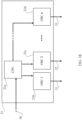
- the tissue stimulating device comprises a computing unit (21), an external power source (22) connected to the computing unit (21), a decoupling circuit (23) connected to the external power source (22) and to the computing unit (21), an arrangement of electromagnetic transducers (1) connected to the computing unit (21) and to the decoupling circuit (23); the computing unit (21) implements the method for tissue stimulation with a frequency scan electric field, the method for tissue stimulation with a frequency scan magnetic field, and methods that combine stimulation with electrical fields and magnetic fields and may be configured with the tissue stimulating device in order to generate activation signals that receive the electromagnetic field transducers, electric filed or magnetic field through the decoupling circuit (23).
- Said control system may also be understood as a tissue stimulating device, a device for stimulating a tissue with electromagnetic fields or simply a device for stimulating a tissue.
- an example of the computing unit (21) being a special purpose computing unit which comprises a central processor unit (CPU) (21a) connected to oscillators from a first OSC 1 (21b), a second oscillator OSC 2 (21c) to an oscillator OSC n (21d) each oscillator having activation signal outputs (31, 32 and 33), wherein n is a natural number equal or greater than cero, according to this the computing unit (21) may have a maximum of n activation signal outputs.
- Activation signal outputs are also named as channels.
- the activation signal output (31, 32 and 33) of each oscillator is connected to the arrangement of electromagnetic transducers (1) directly or through a decoupling circuit (23).
- the CPU (21a) is also connected to a peripheral device selected among others, from storage devices such as a memory unit, a database and a hard drive, input devices such as a keyboard, a camera, a touchscreen display, and a scanner, output devices such as a display and a printer.
- the oscillators are replaced by signals generators.
- each activation signal such as frequency, phase, amplitude, duty cycle
- parameters of each activation signal can be modified by instructions of a remote computing unit, by a user through an HID connected to the tissue stimulating device.
- the computing unit (21) of the tissue stimulating device may use feedback (30), for example, a tissue impedance response feedback in order to dynamically adjust the activation signal outputs (31, 32 and 33) which are received by the transducers and applied to the tissue to stimulate it.
- feedback (30) for example, a tissue impedance response feedback
- the activation signal outputs (31, 32 and 33) which are received by the transducers and applied to the tissue to stimulate it.
- Feedback is a mechanism by which a certain portion of the output of a system is redirected back to the input, for the purpose of controlling its behavior.
- feedback of the tissue impedance response can be used by employing electric field transducers, said feedback making it possible to perceive variations in the tissue impedance response and to dynamically adjust the activation signal.
- feedback is not limited to obtaining the tissue impedance response to the tissue stimulus.
- Feedback may incorporate, for example, measuring the temperature in order to determine tissue fatigue, images of the tissue surface in order to determine tissue vascularization, tissue impedance response measurements, or combinations of these.
- a temperature sensor or temperature measuring device may be used to perceive temperature variations and to dynamically adjust the stimulus activation signal of electrical fields, magnetic fields, or both fields, in order to, for example, avoid lesions on the tissue due to overheating.
- a computing unit is a device that processes data, for example, microcontrollers, microprocessors, DSCs (Digital Signal Controllers), FPGAs (Field Programmable Gate Arrays), CPLDs (Complex Programmable Logic Devices), ASICs (Application Specific Integrated Circuits), SoCs (Systems on Chip), PSoCs (Programmable Systems on Chip), computers, servers, tablets, cellular telephones, smart phones and computer units known to those skilled in the art, and combinations of these.
- This computing unit may include a storage device, display device and/or a Human Interface Device (HID), may be or include a special purpose computing unit programmed to run the method of this disclosure.
- HID Human Interface Device
- a storage device includes, without limiting, RAM memory (cache memory, SRAM, DRAM, DDR), ROM memory (Flash, cache, HDD, SSD, EPROM, EEPROM, removable memory ROM (SD (miniSD, microSD, etc), MMC ( MultiMedia Card ), Compact Flash, SMC (Smart Media Card), SDC (Secure Digital Card), MS (Memory Stick), among others)), CD-ROM, Digital Versatile Disc (DVD) or other optical storage, magnetic cassettes, magnetic tapes, storage or any other means that can be used to store information and which can be accessed by a computer unit, among others known to those skilled in the art, and combinations of these.
- the storage device have memory registers, in which instructions, data structures and software modules stored.
- a display includes, without limiting, monitors is anything capable of being connected to a computing unit and displaying its output.
- CRT monitor flat panel display
- Liquid Crystal D Liquid Crystal Display (LCD) active matrix LCD
- passive matrix LCD passive matrix LCD
- LED displays display projectors
- TV (4KTV, HDTV, Plasma TV, Smart TV) OLED displays
- AMOLED Displays Quantum dot (QD) displays, segments displays, among other devices capable of showing data to a user, known to those skilled in the art, and combinations of these.
- a HID includes, without limiting, keyboard, mouse, trackball, touchpad, pointing stick, joystick, touch screen, among other devices capable of allowing a user to input data into the computing unit of the tissue stimulating device, known to those skilled in the art, and combinations of these.
- the decoupling circuit makes it possible to electrically decouple the external power source from the arrangement of electromagnetic transducers, said circuit may be based on optocouplers, relays, operational amplifiers, resistors, condensers, transformers, combination diodes of these and other electronic elements for electrically decoupling two electrical circuits or elements.
- the external power source makes it possible to provide the electric power required for operation of the arrangement of electromagnetic transducers and may be a device capable of maintaining a power differential between two or more terminals such as an alternating current power source, a continuous current power source , batteries, photovoltaic power source, thermoelectric power source, among other devices capable of maintaining a voltage between two or more terminals known to those skilled in the art, or combinations of these.
- the activation signal received by the transducers of the arrangement of electromagnetic transducers (1), electrical field transducers, or magnetic field transducers may be a signal selected between a direct current or alternating current signal, a pulsed signal, a train of alternating or non-alternating impulsive signals, a square wave signal with variation of the duty cycle, triangular wave signal, sawtooth wave signal, modulated by amplitude (AM), modulated by frequency (FM), modulated by phase (PM), modulated by pulse positions (PPM), modulated by pulse width (PWM), and combinations of these.
- AM amplitude
- FM modulated by frequency
- PM modulated by phase
- PPM modulated by pulse positions
- PWM pulse width
- the programs cited by this disclosure correspond to information, coded or not, in a computing unit and which modify all of the parameters of the activation signal that activates the arrangement transducers (1).
- the signals generators can be selected from the group of professional wave generators, integrated circuits synthesizers DDS (Direct Digital Synthesizer) / DAC (Digital to Analog Conversion), NCO (Numerically Controlled Oscillator), arrays of operational amplifiers in wave generator configuration, bistable oscillator circuits and combinations of the above.
- the signal generator may also be named as wave generator.
- the computing unit (21) makes it possible for one or more activation signals to be applied to each transducer at a determined time, sequentially, out of phase in relation to the other activation signal or to various stimulation signals, randomly or according to a program established for each one of the transducers.
- the activation signal that activates the transducers of the arrangement of electromagnetic transducers (1) may be understood as electromagnetic stimulation signal, electrical stimulation signal when the prevailing phenomenon is from the electrical field, magnetic stimulation signal when the prevailing phenomenon is from the magnetic field.
- the activation signal may be selected, among other things, from direct current or alternating current signal, pulsed signal, a train of alternating or non-alternating impulsive signals, square wave signal with variation of the duty cycle, triangular wave signal, sawtooth wave signal, modulated by amplitude (AM), modulated by frequency (FM), modulated by phase (PM), modulated by pulse positions (PPM), modulated by pulse width (PWM), and combinations of these.
- the method initiates with stimulation of the tissue applying a signal with a determined frequency for a specific period of time which can be limited by a user or can be programmed in a computing unit.
- the method can initiate with a f ie of 1 Hz applied for a ⁇ t e of 1 second, incrementing the frequency f ie a ⁇ f e equal to 1 Hz, applying the new f ie of 2 Hz during a ⁇ t e of 1 second, and continuing increments with the same ⁇ f e , applying the new f ie during a ⁇ t e of 1 second.
- An arrangement of electromagnetic transducers may be a set of "n” electrical field transducers or magnetic field transducers, or a combination of these, with "n” being a natural number greater than or equal to 1.
- Said electromagnetic transducers can be designated as electromagnetic field transducers, they can be electrical field transducers or magnetic field transducers or can be configured by a combination of electrical field transducers and magnetic field transducers. Magnetic field transducers may also be designated as magnetic transducers and electric field transducers may also be designated as electrical transducers. In the case of the electrical field being the prevailing phenomenon, it is understood that said electromagnetic transducers are electrical field transducers, at the same time, when the prevailing phenomenon is the magnetic field, it is understood that the electromagnetic transducers are magnetic field transducers.
- the transducers of the arrangement of electromagnetic transducers have an active face in different shapes which can be selected, among others, from the group of geometric figures such as squares, rectangles, circles, ovals, concentric rings and combinations of these, such that they cover different areas of the external surface of a volume that contains the tissue of interest.
- the active face of a transducer is the surface of the transducer through which the electrical field signal, magnetic field signal, or electromagnetic field signal has greater intensity.
- the electrical field transducers are selected, among others, from the group that consists of engines, electrodes, photoelectric transducers, electrical induction actuators, conducting plates that generate electrical fields, antennas, or combinations of these.
- the electrical field transducers are selected, among others, from the group that consists of engines, electrodes, magnetic induction actuators, magnetic field generating coils with or without a core, electromagnets, antennas and combinations of these.
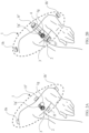
- an arrangement of electromagnetic transducers (1) is placed on the surface of a volume (2), which arrangement comprises from an electromagnetic transducer (1a) to an electromagnetic transducer (1e'), which, in the illustrated example, comprises pairs of transducers, a first pair of electromagnetic transducers comprised of a transducer (1a) and a transducer (1a'), a second pair of electromagnetic transducers, comprised by a transducer (1b) and a transducer (1b'), a third pair of electromagnetic transducers comprised of a transducer (1c) and a transducer (1c'), a fourth pair of electromagnetic transducers comprised of a transducer (1d) and a transducer (1d'), a fifth pair of electromagnetic transducers comprised of a transducer (1e) and a transducer (1e')
- Each pair of transducers face each other and are each oriented with their active face such that it targets the interior of the volume (2) that contains a tissue (3) of interest.
- the arrangement (1) optionally meets a condition of orthogonality in that a plane parallel to any of the surfaces of the active faces of the first pair of transducers is orthogonal to another plane parallel to any of the surfaces of the active faces of the second, third, fourth and fifth pair of transducers, and in addition, any plane parallel to the surfaces of the active faces of the second pair of transducers is orthogonal to any other plane parallel to any of the surfaces of the active faces of the third, fourth and fifth pair of transducers, and additionally, any plane parallel to the surfaces of the active faces of the third pair of transducers is orthogonal to any other plane parallel to any of the surfaces of the active faces of the fourth and fifth pair of transducers, and also any plane parallel to the surfaces of the active faces of the fourth pair of transducers is orthogonal to any other plane parallel to any of the surfaces of the active faces of the fifth pair of transducers, and in addition, projections of the planes of the active faces pointed toward the tissue cover the maximum surface possible of said tissue, with this configuration ensuring optimum
- transducers that comprise each pair of transducers are not completely aligned or parallel to each other, or do not preserve the condition of orthogonality of the transducers described in the previous paragraph, may also succeed in stimulating the tissue (3).
- the active face of the electrical field transducers in the arrangement of electromagnetic transducers (1) is in contact with the external surface of the tissue (3). In this way, less electrical power is required for the operation of the electrical field transducers in comparison with the other alternative where the electrical field transducers are located a determined distance from the external surface of the tissue (3).
- the active face of the transducers that comprise the arrangement of electromagnetic transducers (1) is separated by a determined distance from the external surface of the tissue (3) (necessary, for example, when it is not possible to make physical contact with the external surface of the tissue). In this way, more electrical power may be required for the operation of the electrical field transducers in comparison with the alternative where the electrical field transducers are in contact with the external surface of the tissue (3).
- the active face of the transducers that comprise the arrangement of electromagnetic transducers (1) is separated by a determined distance from the external surface of the tissue (3) and a second group of transducers of the arrangement of electromagnetic transducers (1) is in contact with the external surface of the tissue (3)
- This mixed configuration of the positioning of the transducers makes it possible, for example, to efficiently reach the tissue (3) found in the volume (2) where the surface of said tissue (3) varies such that some areas tolerate physical contact with the active face of the transducer and other areas are difficult to access or do not tolerate such physical contact.
- the active face of at least one of the electrical field transducers in the arrangement of electromagnetic transducers (1) is in contact with the external surface of the tissue (3).
- Projections of the planes of the active faces of the transducers are arranged in the direction of the tissue (3) and cover the maximum possible surface area of said tissue (3), with this configuration ensuring optimum stimulation of the tissue.
- the transducers are not completely aligned or parallel to each other.
- the intensity and direction parameters of a vector of the electrical field toward the interior of the volume (2) depend on the disposition of the transducers around the volume (2) that contains the tissue (3). For example, with an arrangement of electrical field transducers, if the active face is in contact with the surface of the volume (2), then the intensity of the electrical field will be between 2 V/cm and 5 V/cm. If, on the other hand, the electrical field transducers are located a defined distance from the surface, then the intensity value of the electrical field will be between 330 V/cm and 20 kV/cm for distances between 0.01 cm and 50 cm, and optionally between 0.01 cm and 4 cm.
- the intensity value of the electrical field for transducers having their active face in contact with the surface of the tissue may be selected among a range 2 V/cm to 5 V/cm, from 2.1 V/cm to 4.9 V/cm, from 2.2 V/cm to 4.8 V/cm, from 2.3 V/cm to 4.7 V/cm, from 2.4 V/cm to 4.6 V/cm, from 2.5 V/cm to 4.5 V/cm, from 2.6 V/cm to 4.4 V/cm, from 2.7 V/cm to 4.3 V/cm, from 2.8 V/cm to 4.2 V/cm, from 2.9 V/cm to 4.1 V/cm, from 3 V/cm to 4 V/cm, from 3.1 V/cm to 3.9 V/cm, from 3.2 V/cm to 3.8 V/cm, from 3.3 V/cm to 3.7 V/cm, from 3.4 V/cm to 3.6 V/cm, from 2.2
- the intensity value of the electrical field for transducers located a defined distance from the surface of the tissue may be selected among a range from 0.33 kV/cm to 20 kV/cm, from 0.83 kV/cm to 19.5 kV/cm, from 1.33 kV/cm to 19 kV/cm, from 1.83 kV/cm to 18.5 kV/cm, from 2.33 kV/cm to 18 kV/cm, from 2.83 kV/cm to 17.5 kV/cm, from 3.33 kV/cm to 17 kV/cm, from 3.83 kV/cm to 16.5 kV/cm, from 4.33 kV/cm to 16 kV/cm, from 4.83 kV/cm to 15.5 kV/cm, from 5.33 kV/cm to 15 kV/cm, from 5.83 kV/cm to 14.5 kV/cm, from 0.33
- transducers may be located a distance from the surface of the tissue a distance selected among a range from 0.01 cm to 50 cm, from 2 cm to 48 cm, from 4 cm to 46 cm, from 6 cm to 44 cm, from 8 cm to 42 cm, from 10 cm to 40 cm, from 12 cm to 38 cm, from 14 cm to 36 cm, from 16 cm to 34 cm, from 18 cm to 32 cm, from 20 cm to 30 cm, from 22 cm to 28 cm, from 24 cm to 26 cm, from 5 cm to 50 cm, from 10 cm to 50 cm, from 15 cm to 50 cm, from 20 cm to 50 cm, from 25 cm to 50 cm, from 30 cm to 50 cm, from 35 cm to 50 cm, from 40 cm to 50 cm, from 45 cm to 50 cm, from 0.01 cm to 45 cm, from 0.01 cm to 40 cm, from 0.01 cm to 35 cm, from 0.01 cm to 30 cm, from 0.01 cm to 25 cm, from 0.01 cm to 20 cm, from 0.01 cm to 15 cm, from 0.01 cm to 10 cm, from 0.01 cm to 5 cm, from 5
- the arrangement of electromagnetic transducers (1) has at least two electrical field transducers, and at least two of said transducers activate simultaneously by means of a frequency scan for a determined period of time.
- the electromagnetic transducers of the arrangement (1) are disposed over a frame (4) which encloses the volume (2) and the purpose of which is to provide a support structure for the electrical field transducers that are disposed with their active face pointing toward the tissue of interest.
- the frame (4) also can be used to change the shape of the surface of the volume (2) in order to obtain a plane surface that will make it possible to adjust the position of the electrical field transducers such that an optimal intensity of the electrical field is obtained for stimulation of the tissue (3).
- the frame (4) can be supported over the same tissue or be mechanically supported on a fixed or movable base.
- the type of frame (4) can be chosen from the group comprised of shirts, vests, gloves, helmets, glasses, braces, stockings, boots, shoes, scarves, collars, and other structures that provide support to the transducers and combinations of these.
- the frame (4) can cover the volume (2) either totally or partially.
- the base on which the frame (4) is set can be movable in order to make it possible to move the arrangement (1) in relation to the surface of the volume (2) and thus be able to reach different volumes from distinct external points and to vary the vector of the electrical field.
- FIG. 2A illustrates the disposition of an arrangement of electromagnetic transducers (1) over a volume (2) which consists of the arm of an individual. In the interior of the arm is a tissue (3) which it is desired to stimulate electromagnetically.
- Said arrangement of electromagnetic transducers (1) comprises two groups of transducers as detailed below:
- Each pair of transducers is disposed such that the active faces of the transducers that comprise said pair partially face each other, are aligned with their active faces in the direction of the position of the tissue (3) and with their active faces in contact with the skin.
- the arrangement (1) optionally meets a condition of orthogonality in that a plane parallel to any of the surfaces of the active faces of the first pair of transducers is orthogonal to another plane parallel to any of the surfaces of the active faces of the second, and third pair of transducers, and in addition, any plane parallel to the surfaces of the active faces of the second pair of transducers is orthogonal to any other plane parallel to any of the surfaces of the active faces of the first and third pair of transducers, and in addition, projections of the planes of the active faces pointed toward the tissue cover the maximum surface possible of said tissue, with this configuration ensuring optimum stimulation of the tissue.
- transducers that comprise each pair of transducers are not completely aligned or parallel to each other, or do not preserve the condition of orthogonality of the transducers described in the previous paragraph, may also succeed in stimulating the tissue (3).
- biopsy tools for learning the location of the tissue (3), for example: magnetic resonance imaging, computerized tomography, PET (Positron Emission Tomography) scanning, x-rays, Doppler echography, electrocardiograms, diagnosis by palpation, marking with an arrow, among others.
- FIG. 2B illustrates a similar disposition of the transducers, but where the active faces of the transducers are a distance of between 0.01 cm and 50 cm from the surface of the skin of the individual, supported on a frame (4), and optionally between 0.01 cm and 4 cm.
- FIG. 3A illustrates the disposition of an arrangement of electromagnetic transducers (1) over a volume (2) which consists of the abdomen of an individual. In the interior of the abdomen is a tissue (3) which it is desired to stimulate electromagnetically.
- Said arrangement of electromagnetic transducers (1) comprises five groups of transducers as detailed below: A first pair of transducers: a transducer (1i) and a transducer (1i'), a second pair of transducers: a transducer (1j) and a transducer (1j'), a third pair of transducers: a transducer (1k) and a transducer (1k'), a fourth pair of transducers: a transducer (11) and a transducer (1l').
- Said pairs of transducers are disposed radially around an axis parallel to the spinal column, over the abdominal and dorsal area such that the active faces of the transducers face each other and in the direction of the position of the tissue (3) and with their active faces in contact with the skin.
- Projections of the planes of the active faces of the transducers are arranged in the direction of the tissue and cover the maximum possible surface area of said tissue, with this configuration ensuring optimum stimulation of the tissue.
- transducers that comprise each pair are not completely aligned or parallel to each other.
- FIG. 3B illustrates a similar disposition of the transducers, but where the active faces of the transducers are a distance of between 0.01 cm and 50 cm from the surface of the skin in the individual, supported on a frame (4), and optionally between 0.01 cm and 4 cm.
- FIG. 4A illustrates the disposition of an arrangement of electromagnetic transducers (1) over a volume (2) which consists of the knee of an individual.
- a tissue (3) which it is desired to stimulate electromagnetically.
- Said arrangement of electromagnetic transducers (1) comprises two pairs of transducers as detailed below: A first pair of transducers: a transducer (1m) and a transducer (1m') and a second pair of transducers: a transducer (1n) and a transducer (1n').
- Said pairs of transducers are disposed around the knee in the position of the tissue (3) at the height of the patella and such that the active faces of the transducers face each other in the direction of the position of the tissue (3).
- the arrangement (1) optionally meets a condition of orthogonality in that a plane parallel to any of the surfaces of the active faces of the first pair of transducers is orthogonal to another plane parallel to any of the surfaces of the active faces of the second, and third pair of transducers, and in addition, any plane parallel to the surfaces of the active faces of the second pair of transducers is orthogonal to any other plane parallel to any of the surfaces of the active faces of the first and third pair of transducers, and in addition, projections of the planes of the active faces pointed toward the tissue cover the maximum surface possible of said tissue, with this configuration ensuring optimum stimulation of the tissue.
- transducers that comprise each pair of transducers are not completely aligned or parallel to each other, or do not preserve the condition of orthogonality of the transducers described in the previous paragraph, may also succeed in stimulating the tissue (3).
- FIG. 4B illustrates a similar disposition of the transducers, but where the active faces of the transducers are a distance of between 0.01 cm and 50 cm from the surface of the skin in the individual, supported on a frame (4), and optionally between 0.01 cm and 4 cm.
- stage (b) consists of measuring the tissue impedance response stimulated in stage (a).
- the tissue responds with a variation of its parameters which are measured, optionally, using the same electromagnetic transducers. This measurement of stimulated tissue acts as feedback and makes it possible to dynamically change the characteristics of the signal of stage (a).
- stage (c) of this method makes it possible to establish a reference level with the tissue impedance response measured in stage (b).
- Said reference level may be established by a user or determined as a maximum tissue impedance response during a determined time.
- this stage consists of setting a tolerance (NT) at the reference level established in stage (c).
- This NT corresponds to a value in a percentage of the reference level established in stage (c), and can be defined in a computing unit, or be entered by a user.
- the NT in an example, in stage (d'), can be between 5% and 60% and optionally between 25% and 50%.
- the NT can be selected between a range from 5 % to 10 %, from 10 % to 15 %, from 15 % to 20 %, from 20 % to 25 %, from 25 % to 30 %, from 30 % to 35 %, from 35 % to 40 %, from 40 % to 45 %, from 45 % to 50 %, from 50 % to 55 %, from 55 % to 60 %,from 5 % to 10 %, from 5 % to 15 %, from 5 % to 20 %, from 5 % to 25 %, from 5 % to 30 %, from 5 % to 35 %, from 5 % to 40 %, from 5 % to 45 %, from 5 % to 50 %, from 5 % to 55 %, from 5 % to 60 %,from 5 % to 60 %, from 60 % to 55 %, from 55 % to 50 %, from 50 % to 45 %, from 45 % to 40 %, from
- stage e) of the method consists of determining lower tissue stimulation frequencies (f bx ) as the point where the tissue impedance response falls below the tolerance (NT) established in stage (d). For example, three f bx , are determined, a first f b1 equal to 75 kHz, a second f b2 equal to 300 kHz, a third f b3 equal to 450 kHz.
- stage f) of the method makes it possible to determine higher tissue stimulation frequencies (f tx ) as the point where the tissue impedance response returns to the tolerance (NT) established in stage (d). For example, three f tx , are determined, a first f t1 equal to 100 kHz, a second f t2 equal to 350 kHz, a third f t3 equal to 495 kHz.
- the f tx are greater than the f bx .
- the range of frequencies between the lower tissue stimulation frequency (f bx ) and the upper tissue stimulation frequency (f tx ) correspond to the central tissue frequencies.
- the central tissue frequencies refer to the frequencies in which the electromagnetic stimulation is attenuated due to the effects of energy absorption in the tissue, for example, the electromagnetic stimulation signal falls below 25% of a tolerance level (NT).
- NT tolerance level
- the following of this disclosure allows determining stimulation frequency bands in order to focus stimuli in said bands until the tissue impedance response returns to an tolerance level or exceeds a maximum stimulation time.
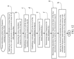
- the first method of tissue stimulation with frequency scan electrical field comprises the following additional stages:
- two f tx are determined: a first f t1 equal to 100 kHz and a second f t2 equal to 350 kHz in stage (e) and two f bx are determined: a first fb equal to 75kHz and a second f b2 equal to 300 kHz in stage (f).
- a first frequency stimulation band corresponds to the frequencies between f b1 and f t1 and a second frequency stimulation band corresponds to the frequencies between f b2 and f t2 .
- a number "x" of frequency stimulation bands can be determined, with "x" being a natural number greater than or equal to 1, that is, from a band between f b1 and f t1 , continuing with a second band between f b2 and f t2 to a band between f bx and f tx .
- a stimulus is applied in a first band of stimulation frequencies from a frequency of f b1 equal to 75 kHz and f t1 equal to 100 kHz in steps from ⁇ f e of 100 Hz in time deltas of ⁇ t e equal to 10 minutes and a second stimulus in a second band of stimulation frequencies from a frequency f b2 equal to 300 kHz and f t2 equal to 350 kHz in steps of ⁇ f e of 1 kHz in time deltas ⁇ t e equal to 5 minutes.
- the f ie and f fe , the ⁇ f e , the NT and the ⁇ t e can all be set by a user in a computing unit and stored in a memory record.
- the ⁇ f e may be a value between 0.1 Hz and 1 kHz, the ⁇ t e may be between about 1 second and about 1 hour, and optionally between about 1 minute and about 1 hour.
- the ⁇ f e can be selected from about 0.1 Hz to about 1 Hz, from about 0.3 Hz to about 0.8 Hz, from about 0.5 Hz to about 0.6 Hz, from about 0.7 Hz to about 0.4 Hz, from about 0.9 Hz to about 0.2 Hz, from about 0.3 Hz to about 1 Hz, from about 0.5 Hz to about 1 Hz, from about 0.7 Hz to about 1 Hz, from about 0.9 Hz to about 1 Hz, from about 0.1 Hz to about 0.8 Hz, from about 0.1 Hz to about 0.6 Hz, from about 0.1 Hz to about 0.4 Hz, from about 0.1 Hz to about 0.2 Hz, from about 0.3 Hz to about 0.5 Hz, from about 0.5 Hz to about 0.7 Hz, from about 0.7 Hz to about 0.9 Hz, from about 0.1 Hz to about 1000 Hz, from about 100 Hz to about 900 Hz, from about 200 Hz to about 800 Hz, from about 300 Hz, from
- the activation signal with the frequency that varies from an initial tissue stimulation frequency (f ie ) to a final tissue stimulation frequency (f fe ) can be applied to a transducer by means of an arrangement of multiplexers that make it possible that one or more electrical field stimulation signals are applied to each transducer at a determined time, sequentially, out of phase in relation to the other stimulation signal or to various stimulation signals, randomly or according to a program established for each of the transducers.
- an activation signal may be comprised of a modulating signal (8) and a carrier signal (9), the carrier signal (9) is optionally of a frequency order greater than that of the modulating signal (8).
- the modulating signal (8) has a frequency of 100 kHz, while the carrier signal (9) has a frequency of less than 1 kHz.
- the f ie and the f fe are between 0.1 Hz and 1000 kHz for both the carrier signal (9) and the modulating signal (8).
- the frequency of f ie and the f fe may be selected from the following ranges: from about 0.1 Hz to about 1 Hz, from about 0.3 Hz to about 0.8 Hz, from about 0.5 Hz to about 0.6 Hz, from about 0.7 Hz to about 0.4 Hz, from about 0.9 Hz to about 0.2 Hz, from about 0.3 Hz to about 1 Hz, from about 0.5 Hz to about 1 Hz, from about 0.7 Hz to about 1 Hz, from about 0.9 Hz to about 1 Hz, from about 0.1 Hz to about 0.8 Hz, from about 0.1 Hz to about 0.6 Hz, from about 0.1 Hz to about 0.4 Hz, from about 0.1 Hz to about 0.2 Hz, from about 0.3 Hz to about 0.5 Hz, from about 0.5 Hz to about 0.7 Hz, from about 0.7 Hz to about 0.9 Hz, from about 0.1 Hz to about 1000 Hz, from about 100 Hz to about 900 Hz, from
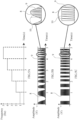
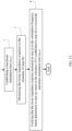
- a frequency vs. time graph is observed, which corresponds to a modulating signal (8) for an activation signal for tissue stimulation with frequency scan electromagnetic fields.
- said modulating signal (8) increases its frequency every second by applying a ⁇ f of 1 Hz, from an initial frequency of 1 Hz to a final frequency of 5 Hz, each frequency being applied for a ⁇ t of 1 s.
- the modulating signal (8) has a sinusoidal form and its frequency varies from an initial frequency of 1 Hz to 5 Hz with ⁇ f of 1 Hz each second, from 1 to 5 s.
- the carrier signal (9) is an impulse type signal with a fixed period (10) of 2 ms or a fixed frequency of 500 Hz.
- the activation signal for an electromagnetic stimulation in which the modulating signal (8) has a squared form and its frequency varies from an initial frequency of 1 Hz to 5 Hz with ⁇ f of 1 Hz each second, from 1 to 5 s.
- the carrier signal (9) is a pulsing type signal with a fixed period (10) of 100 ms or a fixed frequency of 10 kHz.
- the modulating signal (8) has an alternating square wave shape and variation of the duty cycle, its frequency remains fixed, and the carrier signal (9) is of the pulsing type with a fixed period (10) of 200 ⁇ s or a fixed frequency of 5 kHz.
- the activation signal for an electromagnetic stimulation with which the modulating signal (8) has the alternating triangular wave shape, its frequency is fixed, and the carrier signal (9) is of the pulsing type with a fixed period (10) of 2 ⁇ s or a fixed frequency of 500 kHz.
- the modulating signal (8) has a segmented type function that combines an alternating ramp and alternating square wave shape signal
- the carrier signal (9) is of the pulsing type with a fixed period (10) of 2 ⁇ s or a fixed frequency of 500 kHz.
- the modulating signal (8) changes the duty cycle dynamically based on the response of the tissue impedance response measured in the stage (b). Said duty cycle is between 0% and 100% and makes it possible to change the electrical power applied per transducer or transducers to the tissue (3). A duty cycle of 0% can be used, for example, to halt the activation of the signal for a determined period of time.
- the duty cycle of the modulating signal (8) and/or the carrier signal (9) of the activation signal can be selected from 0% to 100%, from 5% to 95%, from 10% to 90%, from 15% to 85%, from 20% to 80%, from 25% to 75%, from 30% to 70%, from 35% to 65%, from 40% to 60%, from 45% to 55%, from 10% to 100%, from 20% to 100%, from 30% to 100%, from 40% to 100%, from 50% to 100%, from 60% to 100%, from 70% to 100%, from 80% to 100%, from 90% to 100%, from 0% to 90%, from 0% to 80%, from 0% to 70%, from 0% to 60%, from 0% to 50%, from 0% to 40%, from 0% to 30%, from 0% to 20%, from 0% to 10%, from 10% to 20%, from 20% to 30%, from 30% to 40%, from 40% to 50%, from 50% to 60%, from 60% to 70%, from 70% to 80%, from 80% to 90%, from 90% to 100%.
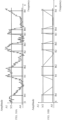
- tissue impedance response is shown, where a tissue is stimulated with frequency scan electromagnetic fields from an initial frequency stimulation (f i ) to a final stimulation frequency (f f ).
- the tissue impedance response is measured and graphed, said response begins with a response value for the tissue impedance that oscillates around a maximum amplitude value (A1) as the tissue stimulation frequency increases in steps from ⁇ f each determined ⁇ t.
- A1 maximum amplitude value
- the tissue impedance response value falls below the tolerance level value (NT) of the tissue impedance response.
- This frequency value is designated as the lower tissue stimulation frequency (f bx ).
- tissue impedance response continues to fall to a minimum amplitude value (A0), and said minimum value is maintained in alignment with tissue stimulation frequency increases.
- the tissue impedance response value begins to rise until it reaches a tissue impedance response value that oscillates around (A1).
- This frequency value is designated as the upper tissue stimulation frequency (f tx ) which is maintained until f f is reached.
- FIG. 9B corresponds to the approximate representation of the response of the example described in FIG. 9A , in which the tissue impedance response is smoothed through the use of averages of the tissue impedance response impedance values, for example, by using digital filters to produce said smoothening.
- the digital filters are selected from, among others, of the group of filters that consist of FIR, Parks-McClellan, minimum squares, Kaiser windows, IIR filters, such as Butterworth, Chebyshev, elliptical filters, among others known to a person versed in the art. It is understood that the purpose of smoothening the signal is to eliminate signal noise or to eliminate atypical values, through a simple average or through digital filters.
- tissue impedance response In reference to FIG. 9C , an example is shown of the tissue impedance response, where a tissue is stimulated with electromagnetic fields with frequency scan from an initial frequency stimulation (f i ) to a final stimulation frequency (f f ).
- the tissue impedance response is measured and graphed, said response begins with a response value for the tissue impedance that oscillates around a maximum amplitude value (A1) as the tissue stimulation frequency increases in steps from ⁇ f at each determined ⁇ t.
- A1 maximum amplitude value
- the tissue impedance response value falls below the tolerance level value (NT) of the tissue impedance response.
- This frequency value is designated as the lower tissue stimulation frequency (f bx ).
- tissue stimulation frequency increases, the tissue impedance response continues to fall to a minimum amplitude value (A0), and said minimum value is maintained in alignment with tissue stimulation frequency increases until it reaches a final stimulation frequency (f f ).
- FIG. 9D corresponds to an example of the approximate representation of the response of the example described in FIG. 9C , in which the tissue impedance response is smoothed through the use of averages of the tissue impedance response impedance values, for example, by using digital filters to produce said smoothening.
- t max of stage (i) may be between about 1 hour and about 18 hours.
- t max of stage (i) may be between about 1 hour and about 18 hours.
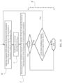
- stage (k) the following verifications are conducted:
- tissue impedance response of a tissue stimulated with electrical field or magnetic field by frequency scan from a f i The tissue impedance response is measured and graphed simultaneously. Said response begins with a tissue impedance response value that oscillates around a maximum amplitude value (A1).
- tissue stimulation frequency increases in steps from ⁇ f, it continues oscillating around (A1) until the stimulation frequency reaches a first lower tissue stimulation frequency (f b1 ), which corresponds to a point at which the tissue impedance response value falls below the NT.
- tissue impedance response value continues to fall to a tissue impedance response value that oscillates around a minimum amplitude value (A0) where it is maintained until the tissue impedance response value begins to increase until it reaches the (A1). This point is a first upper tissue stimulation frequency (f t1 ).
- the range of frequencies between f b1 and f t1 is a first stimulation band.
- a second stimulation frequency band range is found in a range of frequencies between f b2 and f t2
- a third stimulation frequency band range is found in a range of frequencies between f b3 and f t3
- a fourth stimulation frequency band range is found in a range of frequencies between f b4 y f t4 , until frequency stimulation reaches f f .
- These stimulation bands refer to a range of central tissue frequencies which present a biochemical imbalance.
- the range of frequencies between the lower tissue stimulation frequency (f bx ) and the upper tissue stimulation frequency (f tx ) correspond to the central tissue frequencies.
- the activation signal for the electrical field transducers changes with tissue temperature feedback.
- the stimulated biological tissue is in an animal.
- the stimulated biological tissue is an animal.
- the electromagnetic transducers are in contact with an external surface of the tissue.
- the electromagnetic transducers are located a determined distance from an external surface of the biological tissue.
- a first portion of the electromagnetic transducers are in contact with an external surface of the biological tissue and a second portion of the electromagnetic transducers are located a determined distance from the external surface of the biological tissue.
- the electromagnetic transducers are activated according to a defined sequence.
- the electromagnetic transducers are activated randomly.
- the activation signal is applied to each transducer at a determined time, sequentially, out of phase in relation to the other activation signal or to various stimulation signals, randomly or according to a program established for each one of the transducers.
- FIG. 10B corresponds to the approximate representation of the response of the example described in FIG. 10A , in which the tissue impedance response is smoothed, for example, through the use of averages of the response values in amplitude, using the tools described above.
- a magnetic field stimulus is applied through the arrangement of electromagnetic transducers that receive an activation signal, the frequency of which varies from an initial tissue stimulation frequency (f im ) to a final tissue stimulation frequency (f fm ), with increases or decreases in steps of a frequency delta ( ⁇ f m ) during a time delta ( ⁇ t m ), which makes it possible to obtain benefits from a combined stimulation with magnetic field and electrical field, such as, for example, broadening the electrical field stimulation area of the tissue.
- the magnetic field stimulus is orthogonal to the electrical field stimulus.
- the magnetic field transducers are optionally arranged such that they generate magnetic fields orthogonal to the electrical fields of the electrical field transducers, such that, optimum stimulation of the tissue is provided.
- the magnetic field transducers may be arranged in different configurations, in which the magnetic fields generated by said magnetic field transducers are not orthogonal to the electrical fields generated by electrical field transducers in the arrangement.
- the transducers of the arrangement of electromagnetic transducers (1) are magnetic field transducers and may or may not be faced by another magnetic field transducer or another electrical field transducer.
- the activation signal can be selected, among other things, from direct current or alternating current signal, pulsed signal, a train of alternating or non-alternating impulsive signals, square wave signal with variation of the duty cycle, triangular wave signal, sawtooth wave signal, modulated by amplitude (AM), modulated by frequency (PM), modulated by phase (PM), modulated by pulse positions (PPM), modulated by pulse width (PWM), and combinations of these.
- direct current or alternating current signal pulsed signal, a train of alternating or non-alternating impulsive signals, square wave signal with variation of the duty cycle, triangular wave signal, sawtooth wave signal, modulated by amplitude (AM), modulated by frequency (PM), modulated by phase (PM), modulated by pulse positions (PPM), modulated by pulse width (PWM), and combinations of these.
- AM amplitude
- PM modulated by frequency
- PM modulated by phase
- PPM modulated by pulse positions
- PWM pulse width
- tissue stimulation using magnetic fields is tissue stimulation using magnetic fields and comprising the following stages:
- the magnetic transducers are arranged over a volume (2) that contains the tissue (3) to be stimulated. Each magnetic transducer generates a magnetic field that is applied to the tissue (3).
- the field generated with each transducer is controlled by an activation signal which, optionally, has an initial frequency (f im ) that changes over time to a final frequency (f fm ), which can be higher than, lower than or equal to the initial frequency.
- the intensity of the magnetic field generated by the magnetic field transducers when activated by the activation signal can be between 0.1 mT (milliteslas) equivalent to 1 Gauss, and 200 mT (milliteslas), equivalent to 2000 Gauss, and optionally between 40 mT (milliteslas) equivalent to 400 Gauss, and 200 mT (milliteslas), equivalent to 2000 Gauss.
- the intensity generated by the magnetic field transducers is selected among the range from 1 mT to 10 mT, from 10 mT to 20 mT, from 20 mT to 30 mT, from 30 mT to 40 mT, from 40 mT to 50 mT, from 50 mT to 60 mT, from 60 mT to 70 mT, from 70 mT to 80 mT, from 80 mT to 90 mT, from 90 mT to 100 mT, from 100 mT to 110 mT, from 110 mT to 120 mT, from 120 mT to 130 mT, from 130 mT to 140 mT, from 140 mT to 150 mT, from 150 mT to 160 mT, from 160 mT to 170 mT, from 170 mT to 180 mT, from 180 mT to 190 mT, from 190 mT to 200 mT,from 1 mT to 10 mT, from 1
- ⁇ t m refers to a period of time which may vary as a function of the application required to use the method.
- the f im and f fm , the ⁇ f m and the ⁇ t m are set by a user in a computing unit and stored in a memory record.
- the applicable range values for f im , f fm , ⁇ f m and ⁇ t m for magnetic stimulation are the same used for f ie , f fe , ⁇ f e and ⁇ t e in electromagnetic stimulation cited previously in this disclosure.
- the f im and f fm are in a range of frequencies between about 0.1 Hz and about 1000 kHz, and optionally between about 25 Hz and about 1000 kHz.
- the frequency of f im and the f fm may be selected from the following ranges: from about 0.1 Hz to about 1 Hz, from about 0.3 Hz to about 0.8 Hz, from about 0.5 Hz to about 0.6 Hz, from about 0.7 Hz to about 0.4 Hz, from about 0.9 Hz to about 0.2 Hz, from about 0.3 Hz to about 1 Hz, from about 0.5 Hz to about 1 Hz, from about 0.7 Hz to about 1 Hz, from about 0.9 Hz to about 1 Hz, from about 0.1 Hz to about 0.8 Hz, from about 0.1 Hz to about 0.6 Hz, from about 0.1 Hz to about 0.4 Hz, from about 0.1 Hz to about 0.2 Hz, from about 0.3 Hz to about 0.5 Hz, from about 0.5 Hz to about 0.7 Hz, from about 0.7 Hz to about 0.9 Hz, from about 0.1 Hz to about 1000 Hz, from about 100 Hz to about 900 Hz, from about 200
- the activation signal used for magnetic fields can also be configured by a carrier signal (9) and a modulating signal (8).
- the f im and the f fm are between 0.1 Hz y 500 kHz for both the carrier signal (9) and the modulating signal (8), with the carrier signal (9) optionally of an order of frequency greater than that of the modulating signal (8).
- the NT in an example, in stage (d'), can be between 5% and 60% and optionally between 25% and 50%.
- the applicable range values for NT for magnetic stimulation are the same used for NT in electromagnetic stimulation cited before in this document.
- the range of frequencies between the lower tissue stimulation frequency (f bx ) and the upper tissue stimulation frequency (f tx ) correspond to the central tissue frequencies.
- control unit can be programmed so that it chooses the initial stimulation frequency (f im ), the final tissue stimulation frequency (f fm ) and the frequency delta ( ⁇ f m ) and, optionally, these characteristics are set by a user and stored in a memory for application of the method.
- a pulsing function may be used to activate the magnetic field, where the f im and the f fm are between 0.1 Hz and 1000 kHz, the ⁇ f m has a range between 0.1 Hz and 1 kHz, the ⁇ t m is between 1 second and 1 hour, and optionally between 1 minute and 1 hour.
- an activation signal for square wave shape frequency scan magnetic stimulation in a frequency from 1 Hz to 50 kHz.
- frequencies from 1 Hz to 5 kHz applying a variation of the duty cycle of between 0.4% and 5% for a maximum magnetic field intensity of 200 mT (milliteslas) equivalent to 2000 Gauss.
- frequencies from 5 kHz to 50 kHz applying a variation of the duty cycle of between 5% and 25% for a maximum magnetic field intensity of 40 mT (milliteslas) equivalent to 400 Gauss.
- This frequency scan is applied for a t max of 1 hour and may be repeated each day, for 6 days.
- stage (f') the following stages are completed:
- t max in stage (i') can be between about 1 hour and about 18 hours.
- t max "about” should be understood as a 5% variation of the maximum stimulation time.
- stage (k') the following verifications are performed:
- tissue stimulation can also be applied by using spatial scanning, as described in the Colombian application NC 2018/0001282 filed on 7 February 2018 .
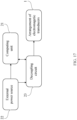
- the activation signal obeys to a defined pattern, which follows the following steps:
- step D the index value changes randomly and returns to step C).
- the transducers can be activated randomly, and it is also possible to activate them in defined sequences, which will depend on the stimulation of the target tissue.
- the range of frequencies between the lower tissue stimulation frequency (f bx ) and the upper tissue stimulation frequency (f tx ) correspond to the central tissue frequencies.
- the activation signal for the electrical field transducers changes with tissue temperature feedback.
- the stimulated biological tissue is in an animal.
- the stimulated biological tissue is an animal.
- the electromagnetic transducers are in contact with an external surface of the tissue.
- the electromagnetic transducers are located a determined distance from an external surface of the biological tissue.
- a first portion of the electromagnetic transducers are in contact with an external surface of the biological tissue and a second portion of the electromagnetic transducers are located a determined distance from the external surface of the biological tissue.
- the electromagnetic transducers are activated according to a defined sequence.
- the electromagnetic transducers are activated randomly.
- the activation signal is applied to each transducer at a determined time, sequentially, out of phase in relation to the other activation signal or to various stimulation signals, randomly or according to a program established for each one of the transducers.
- a tissue (3) with an arrangement of electromagnetic transducers (1) with electrical field transducers and magnetic field transducers applying a combination of electrical stimulation signals and magnetic stimulation signals that combine their characteristics on the basis of the feedback of magnetic field intensity applied to the tissue, the feedback of the tissue impedance or a combination of the two.
- a third method for tissue stimulation is a method for stimulating a tissue with both electric fields and magnetic fields, the method comprising:
- the computing unit makes the decision to halt the stimulus to avoid tissue damage.
- the activation signal of the magnetic transducers follow a pattern that changes with tissue temperature feedback, and this also applies to the activation signal of the electrical field transducers.
- the arrangement of electromagnetic transducers (1) comprises magnetic field transducers and electrical field transducers overlapped with each other, disposed orthogonally with each other, with their active faces in the direction of the tissue (3) in order to apply a combined stimulation by electrical and magnetic fields following an activation pattern.
- tissue stimulation is performed in an individual with the following initial diagnosis of poorly differentiated malignant neoplasia shown in FIG. 11A .
- Immuno-histo-chemical markers present the following results:
- the tissue was stimulated with a device for stimulating a tissue with electromagnetic fields which implements the method for stimulating a tissue of the present disclosure.
- the device used the following arrangement of electromagnetic transducers:
- a magnetic field stimulus and an electrical field stimulus are applied orthogonally to each other.
- the computing unit of the device generates the activation signal according to a program established for each magnetic transducer. Specifically, the pair of magnetic field transducers was connected to a first and second channel of the device and received an activation signal having an amplitude of 72 Vpp (Peak-to-Peak Voltage) and applied in a frequency scan ranging from an initial tissue stimulation frequency f im equal to 1 Hz to a final tissue stimulation frequency f fm equal to 50 kHz.
- Vpp Peak-to-Peak Voltage
- the first stimulation frequency band corresponded to a frequency range from a first lower tissue stimulation frequency f b1 equal to 1 Hz to a first upper tissue stimulation frequency f t1 equal to 5 kHz
- the second stimulation frequency band corresponded to a frequency range from a second lower tissue stimulation frequency f b2 equal to 5 kHz to a second upper tissue stimulation frequency f t2 equal to 50 kHz.
- the two pairs of electric field transducers were connected respectively to a third, fourth, fifth and sixth channel of the device.
- Each pair received an activation signal having an amplitude of 72 Vpp (Peak-to-Peak Voltage).
- the carrier signal was an alternating impulse train with a fixed frequency of 150 kHz modulated in PWM having a duty cycle of 15%; the modulating signal was a triangular waveform of varying frequency.
- This activation signal was applied in a frequency scan ranging from an initial tissue stimulation frequency f ie equal to 1 kHz to a final tissue stimulation frequency f fe equal to 500 kHz.
- the first stimulation frequency band corresponded to a frequency range from a first lower tissue stimulation frequency f b1 equal to 1 kHz to a first upper tissue stimulation frequency f t1 equal to 50 kHz
- the second stimulation frequency band corresponded to a frequency range from a second lower tissue stimulation frequency f b2 equal to 150 kHz to a second upper tissue stimulation frequency f t2 equal to 250 kHz
- the third stimulation frequency band corresponded to a frequency range from a third lower tissue stimulation frequency f b3 equal to 320 kHz to a third upper tissue stimulation frequency f t3 equal to 420 kHz.
- the measured average power delivered to the tissue of above example ranged between 0.2 W to 0.5W.
- the electrode temperature never surpassed 40°C.
- the frequency delta ( ⁇ f) steps were 500 Hz
- the time delta ( ⁇ t) steps were 1 second.
- FIG. 11B a photograph is shown of the same individual showing a marked reduction of the mass of the malignant tumor after the delivery schedule noted above. Additionally, the laboratory report after the stimulation was negative for metastasis.
- the tissue impedance signal (34) starts to show a drop-off at about 140 seconds, when the tissue stimulating frequency applied was about 320 kHz. This drop-off, or valley, lasted until about 340 seconds, when the tissue stimulating frequency applied reached about 420 kHz.
- tissue impedance response valley was not bound to specific frequencies over the course of each application. Instead, slight frequency shifts of the tissue impedance response were observed, typically showing a +/- 20% variation. Over the course of the 6 days of delivery, the tissue impedance valleys tended to disappear.
- FIG. 11D shows a smoothed tissue impedance response signal (35) and was achieved by averaging the tissue impedance response signal (34).
- Reference level refers to a value stablished by a user or computing unit for escalate or fitting or fixing the tissue impedance response in an amplitude range values to be presented or analyzed to a user.
- Stimulation frequency bands Refers to a range of frequencies where the amplitude tissue impedance response falls below the tolerance.
Landscapes
- Health & Medical Sciences (AREA)
- Life Sciences & Earth Sciences (AREA)
- Engineering & Computer Science (AREA)
- Biomedical Technology (AREA)
- Nuclear Medicine, Radiotherapy & Molecular Imaging (AREA)
- Radiology & Medical Imaging (AREA)
- Animal Behavior & Ethology (AREA)
- General Health & Medical Sciences (AREA)
- Public Health (AREA)
- Veterinary Medicine (AREA)
- Biophysics (AREA)
- Heart & Thoracic Surgery (AREA)
- Pathology (AREA)
- Physics & Mathematics (AREA)
- Medical Informatics (AREA)
- Molecular Biology (AREA)
- Surgery (AREA)
- Physiology (AREA)
- Hospice & Palliative Care (AREA)
- Oncology (AREA)
- Neurology (AREA)
- Magnetic Treatment Devices (AREA)
- Electrotherapy Devices (AREA)
Claims (5)
- Vorrichtung zum Stimulieren eines Gewebes mit elektromagnetischen Feldern, wobei die Vorrichtung umfasst:- eine Recheneinheit (21);- eine externe Stromquelle (22), die mit der Recheneinheit verbunden ist:- eine Entkopplungsschaltung (23), die mit der externen Stromquelle und mit der Recheneinheit verbunden ist; und- eine Anordnung von elektromagnetischen Wandlern (1), die mit der Recheneinheit und mit der Entkopplungsschaltung verbunden ist, wobei die Anordnung funktionell über dem Gewebe angeordnet ist;wobei die Recheneinheit ein Verfahren zum Stimulieren eines Gewebes mit elektromagnetischen Feldern implementiert, wobei das Verfahren die folgenden Phasen umfasst:a) Anwenden eines Stimulus eines elektrischen Feldes auf ein Gewebe durch die Anordnung von elektromagnetischen Wandlern, die ein Aktivierungssignal empfangen, deren Frequenz von einer anfänglichen Gewebestimulationsfrequenz fie zu einer endgültigen Gewebestimulationsfrequenz ffe mit Inkrementen oder Dekrementen in Schritten eines Frequenzdeltas Δfe während eines Zeitdeltas Δte variiert;b) Messen der Gewebeimpedanzantwort auf den Stimulus von Phase a);c) Festlegen eines Referenzpegels mit der in Phase b) gemessenen Gewebeimpedanzantwort;d) Festlegen einer Toleranz NT auf den in Phase c) festgelegten Referenzpegel;e) Bestimmen von unteren Gewebestimulationsfrequenzen fbx als Punkt, an dem die Gewebeimpedanzantwort unter die in Phase d) festgelegte Toleranz NT fällt; undf) Bestimmen von oberen Gewebestimulationsfrequenzen ftx als Punkt, an dem die Gewebeimpedanzantwort zu der in Phase d) festgelegten Toleranz NT zurückkehrt;wobei die oberen Gewebestimulationsfrequenzen ftx größer sind als die unteren Gewebestimulationsfrequenzen fbx und x eine natürliche Zahl größer als gleich 1 ist.
- Vorrichtung nach Anspruch 1, wobei die Toleranz NT zwischen etwa 25 % und etwa 50 % liegt; oder optionalwobei die anfängliche Gewebestimulationsfrequenz fie und die endgültige Gewebestimulationsfrequenz ffe zwischen etwa 0,1 Hz und etwa 1000 kHz liegen; oder optionalwobei das Frequenzdelta Δfe ein Wert zwischen etwa 0,1 Hz und etwa 1 kHz ist; oder optionalwobei das Zeitdelta Δte zwischen etwa 1 Sekunde und etwa 1 Stunde liegt; oder optionalwobei die Recheneinheit eine Spezialrecheneinheit ist, die eine zentrale Prozessoreinheit (Central Processor Unit, CPU) umfasst, welche mit Oszillatoren von einem ersten Oszillator OSC 1, einem zweiten Oszillator OSC 2 bis zu einem Oszillator OSC n verbunden ist, wobei jeder Oszillator einen Aktivierungssignalausgang aufweist;wobei n eine natürliche Zahl größer als Null ist.
- Vorrichtung nach Anspruch 1, wobei nach Phase f) die folgenden Phasen durchlaufen werden:g) Bestimmen von Stimulationsfrequenzbändern auf Basis der unteren gewebestimulierenden Frequenzen fbx, die in Phase e) bestimmt werden, zusammen mit den oberen gewebestimulierenden Frequenzen ftx, die in Phase f) bestimmt werden, undh) Anwenden eines Stimulus eines elektrischen Feldes auf ein Gewebe durch eine Anordnung von elektromagnetischen Wandlern, die ein Aktivierungssignal empfangen, deren Frequenz um die Stimulationsfrequenzbänder variiert, die in Phase g) bestimmt werden, mit Inkrementen oder Dekrementen in Schritten eines Frequenzdeltas Δfe während eines Zeitdeltas Δte;i) Festlegen einer maximalen Stimulationszeit tmax;j) Messen der Gewebeimpedanzantwort auf den Stimulus von Phase h) undk) Verifizieren, dass die Gewebeimpedanzantwort, die in Phase j) in den Stimulationsfrequenzbändern gemessen wird, die in Phase g) bestimmt werden, zu der Toleranz NT zurückkehrt, die in Phase d) festgelegt wird, oder die maximale Stimulationszeit tmax überschreitet, und optionalwobei Phase k) die folgenden Verifizierungen umfasst:- falls die maximale Stimulationszeit tmax überschritten wird, dann abschließen;- falls die maximale Stimulationszeit tmax nicht überschritten wird und die Gewebeimpedanzantwort, die in Phase j) gemessen wird, unterhalb der Toleranz NT liegt, die in Phase d) festgelegt wird, Wiederholen von Phase h); und- falls die Gewebeimpedanzantwort, die in Phase j) in den Stimulationsfrequenzbändern gemessen wird, die in Phase g) bestimmt werden, die Toleranz NT überschreitet, die in Phase d) festgelegt wird, dann abschließen.
- Vorrichtung nach Anspruch 1, wobei ein Benutzer in einer Recheneinheit dafür konfiguriert ist, die anfängliche Gewebestimulationsfrequenz fie, die endgültige Gewebestimulationsfrequenz ffe, das Frequenzdelta Δfe, das Zeitdelta Δte, die Toleranz NT, die unteren Gewebestimulationsfrequenzen fbx und die oberen Gewebestimulationsfrequenzen ftx festzulegen und außerdem im Speicher zu speichern, oder optionalwobei die Toleranz NT zwischen etwa 25 % und etwa 50 % liegt; oder optionalwobei in Phase a) das Aktivierungssignal unter anderem ausgewählt wird aus einem direkten oder einem alternierenden Signal, einem gepulsten Signal oder nichtalternierenden Impulsfolgen, einem Rechteckwellensignal mit Variation des Tastverhältnisses, einem Dreieckwellensignal, einem Sägezahnwellensignal, moduliert durch Amplitude, moduliert durch Frequenz, moduliert durch Phase, moduliert durch Impulspositionen, oder Kombinationen von diesen; oder optionalwobei die anfängliche Gewebestimulationsfrequenz fie und die endgültige Gewebestimulationsfrequenz ffe zwischen etwa 0,1 Hz und etwa 1000 kHz liegen; oder optionalwobei das Frequenzdelta Δfe ein Wert zwischen etwa 0,1 Hz und etwa 1 kHz ist; oder optionalwobei das Zeitdelta Δte zwischen etwa 1 Sekunde und etwa 1 Stunde liegt.
- Vorrichtung nach Anspruch 1, wobei in Phase e) der Frequenzbereich zwischen der unteren Gewebestimulationsfrequenz fbx und der oberen Gewebestimulationsfrequenz ftx den mittleren Gewebefrequenzen entspricht; oder optionalwobei sich das Aktivierungssignal für die elektrischen Feldwandler mit der Gewebetemperatur-Rückmeldung ändert; oder optionalwobei sich das stimulierte biologische Gewebe in einem Tier befindet; oder optionalwobei das stimulierte biologische Gewebe ein Tier ist; oder optionalwobei sich die elektromagnetischen Wandler in Kontakt mit einer externen Oberfläche des Gewebes befinden; oder optionalwobei sich die elektromagnetischen Wandler in einem bestimmten Abstand von einer externen Oberfläche des biologischen Gewebes befinden; oder optionalwobei sich eine erster Abschnitt der elektromagnetischen Wandler in Kontakt mit einer externen Oberfläche des biologischen Gewebes befindet und sich ein zweiter Abschnitt der elektromagnetischen Wandler in einem bestimmten Abstand von der externen Oberfläche des biologischen Gewebes befindet; oder optionalwobei die elektromagnetischen Wandler gemäß einer definierten Abfolge aktiviert werden; oder optionalwobei die elektromagnetischen Wandler zufällig aktiviert werden; oder optionalwobei das Aktivierungssignal auf jeden Wandler zu einer bestimmten Zeit, sequenziell, phasenversetzt in Relation zu dem anderen Aktivierungssignal oder zu verschiedenen Stimulationssignalen, zufällig oder gemäß einem Programm, das für jeden der Wandler festgelegt ist, angewendet wird.
Applications Claiming Priority (2)
| Application Number | Priority Date | Filing Date | Title |
|---|---|---|---|
| CONC2018/0001283A CO2018001283A1 (es) | 2018-02-07 | 2018-02-07 | Método de estimulación de tejidos con campos eléctricos y magnéticos por barrido en frecuencia |
| PCT/IB2019/051007 WO2019155407A2 (en) | 2018-02-07 | 2019-02-07 | Tissue-stimulating method using frequency scanning of electric and magnetic fields |
Publications (4)
| Publication Number | Publication Date |
|---|---|
| EP3749409A2 EP3749409A2 (de) | 2020-12-16 |
| EP3749409A4 EP3749409A4 (de) | 2021-11-10 |
| EP3749409C0 EP3749409C0 (de) | 2025-01-08 |
| EP3749409B1 true EP3749409B1 (de) | 2025-01-08 |
Family
ID=67512120
Family Applications (1)
| Application Number | Title | Priority Date | Filing Date |
|---|---|---|---|
| EP19752004.2A Active EP3749409B1 (de) | 2018-02-07 | 2019-02-07 | Vorrichtung zur gewebestimulation mittels frequenzabtastung von elektrischen und magnetischen feldern |
Country Status (16)
| Country | Link |
|---|---|
| US (2) | US11826568B2 (de) |
| EP (1) | EP3749409B1 (de) |
| JP (2) | JP7490558B2 (de) |
| KR (1) | KR102801732B1 (de) |
| CN (1) | CN111936197B (de) |
| AU (1) | AU2019219588B2 (de) |
| BR (1) | BR112020016152A2 (de) |
| CA (1) | CA3091623A1 (de) |
| CO (1) | CO2018001283A1 (de) |
| ES (1) | ES3018609T3 (de) |
| IL (1) | IL276533B2 (de) |
| MX (1) | MX2020008284A (de) |
| PL (1) | PL3749409T3 (de) |
| SA (1) | SA520412595B1 (de) |
| SG (1) | SG11202007509RA (de) |
| WO (1) | WO2019155407A2 (de) |
Families Citing this family (19)
| Publication number | Priority date | Publication date | Assignee | Title |
|---|---|---|---|---|
| CO2018007468A1 (es) | 2018-07-16 | 2020-01-17 | Panacea Quantum Leap Tech Llc | Método de estimulación de tejidos con campos electromagnéticos que generan jerk |
| US12121739B2 (en) * | 2019-12-31 | 2024-10-22 | Novocure Gmbh | Methods, systems, and apparatuses for managing temperatures induced by alternating fields |
| WO2021154736A1 (en) * | 2020-01-27 | 2021-08-05 | Alternating Current Treatment Therapy Medical Inc. | Method and apparatus for inhibiting the growth of proliferating cells or viruses |
| US20210353356A1 (en) | 2020-05-14 | 2021-11-18 | Singlepass Transsepat, Inc. | Tubular large bore transseptal crossing sheath |
| US12263336B2 (en) | 2020-07-22 | 2025-04-01 | Nexalin Technology, Inc. | Alternating current dynamic frequency stimulation system and method for opioid use disorder (OUD) and substance use disorder (SUD) |
| US11944806B2 (en) | 2020-07-22 | 2024-04-02 | Nexalin Technology, Inc. | Transcranial alternating current dynamic frequency stimulation method for anxiety, depression, and insomnia (ADI) |
| US11872397B2 (en) * | 2020-07-22 | 2024-01-16 | Nexalin Technology, Inc. | Transcranial alternating current dynamic frequency stimulation (TACS) system |
| WO2022046777A1 (en) | 2020-08-25 | 2022-03-03 | Cross Vascular, Inc. | Transseptal crossing system |
| WO2022112945A1 (en) * | 2020-11-25 | 2022-06-02 | Novocure Gmbh | Increasing the efficacy of tumor treating fields (ttfields) by applying the ttfields at peak intensity less than half the time |
| WO2022147153A1 (en) * | 2020-12-30 | 2022-07-07 | Novocure Gmbh | Amplitude modulation for tumor treating fields |
| US12161876B2 (en) | 2020-12-30 | 2024-12-10 | Novocure Gmbh | Amplitude modulation for tumor treating fields |
| KR102624063B1 (ko) * | 2021-05-06 | 2024-01-11 | 연세대학교 산학협력단 | 암 치료용 디바이스 및 이의 제어 방법 |
| IT202100015971A1 (it) * | 2021-06-18 | 2022-12-18 | Non Ionizing Radiation Personal Shielding S R L | Dispositivo retroazionato per la ionorisonanza ciclotronica |
| WO2023105391A1 (en) * | 2021-12-07 | 2023-06-15 | Novocure Gmbh | Compact dc system for delivering a square wave ac signal |
| TW202430241A (zh) * | 2022-09-30 | 2024-08-01 | 瑞士商諾沃庫勒有限責任公司 | 在使用交流電場治療受試者時藉由控制上升特性來降低電知覺 |
| DE102022130619A1 (de) * | 2022-11-18 | 2024-05-23 | Petra Falke | Verfahren zum Erzeugen elektromagnetischer Felder und eine Vorrichtung mit einer solchen Vorrichtung |
| IT202300003723A1 (it) * | 2023-03-01 | 2024-09-01 | Tecnica Scient Service S R L | Dispositivo per il trattamento di condizioni infiammatorie tramite p.e.m.f. (pulsed electro-magnetic field) |
| CN117282024B (zh) * | 2023-09-22 | 2024-05-14 | 赛福凯尔(绍兴)医疗科技有限公司 | 电场发射系统 |
| US20250108211A1 (en) * | 2023-09-29 | 2025-04-03 | Novocure Gmbh | Apparatus and method of reapplying transducer arrays to a patient |
Family Cites Families (19)
| Publication number | Priority date | Publication date | Assignee | Title |
|---|---|---|---|---|
| RU2091089C1 (ru) * | 1989-03-06 | 1997-09-27 | Товарищество с ограниченной ответственностью "ОКБ РИТМ" | Устройство для электростимуляции |
| JPH0817827B2 (ja) * | 1992-07-23 | 1996-02-28 | 征夫 内海 | 磁気治療器 |
| CA2257266C (en) * | 1996-06-06 | 2013-06-25 | Lawson Research Institute | Electrotherapy device using low frequency magnetic pulses |
| WO1998000732A1 (en) * | 1996-07-03 | 1998-01-08 | The Government Of The United States Of America Represented By The Secretary, Department Of Health And Human Services | Ultrasound-hall effect imaging system and method |
| DE60112886T2 (de) * | 2000-01-07 | 2006-06-14 | Biowave Corp | Elektrotherapiegerät |
| EP1259596A4 (de) | 2000-02-17 | 2004-12-22 | Novocure Limited | VERFAHREN UND VORRICHTUNG ZUR ZERSTöRUNG VON SICH TEILENDEN ZELLEN |
| JP3503135B2 (ja) * | 2000-03-17 | 2004-03-02 | 株式会社テクノリンク | 生体刺激装置 |
| JP4815549B2 (ja) | 2004-04-23 | 2011-11-16 | 国立大学法人金沢大学 | 温熱治療装置 |
| US7613518B2 (en) | 2004-06-15 | 2009-11-03 | Encore Medical Asset Corporation | Interferential and neuromuscular electrical stimulation system and apparatus |
| US7865236B2 (en) * | 2004-10-20 | 2011-01-04 | Nervonix, Inc. | Active electrode, bio-impedance based, tissue discrimination system and methods of use |
| US8788044B2 (en) * | 2005-01-21 | 2014-07-22 | Michael Sasha John | Systems and methods for tissue stimulation in medical treatment |
| JP2008543386A (ja) | 2005-06-15 | 2008-12-04 | フラレックス・セラピューティクス・インコーポレイテッド | 治療用低周波パルス磁場およびそのための装置 |
| WO2007115362A1 (en) * | 2006-04-07 | 2007-10-18 | Global Energy Medicine Pty Ltd | In vivo stimulation of cellular material |
| GB0709834D0 (en) * | 2007-05-22 | 2007-07-04 | Gillbe Ivor S | Array stimulator |
| EP2020250A1 (de) * | 2007-07-26 | 2009-02-04 | Johannes Josephus Maria Cuppen | Vorrichtung und Verfahren zur elektromagnetischen Stimulation eines Prozesses innerhalb lebender Organismen |
| JP6654132B2 (ja) * | 2013-03-15 | 2020-02-26 | ネイティヴィス、インコーポレイテッド | ガン治療などの治療を施すためのコントローラ及び可撓性コイル |
| US20160106976A1 (en) * | 2014-01-10 | 2016-04-21 | Theodore R. Kucklick | Device and method for treatment of sleep apnea |
| US10376145B2 (en) * | 2015-02-24 | 2019-08-13 | Elira, Inc. | Systems and methods for enabling a patient to achieve a weight loss objective using an electrical dermal patch |
| EP3416719B1 (de) * | 2016-02-19 | 2024-08-14 | Nalu Medical, Inc. | Vorrichtung mit verbesserten stimulationswellenformen |
-
2018
- 2018-02-07 CO CONC2018/0001283A patent/CO2018001283A1/es unknown
-
2019
- 2019-02-07 CA CA3091623A patent/CA3091623A1/en active Pending
- 2019-02-07 IL IL276533A patent/IL276533B2/en unknown
- 2019-02-07 MX MX2020008284A patent/MX2020008284A/es unknown
- 2019-02-07 AU AU2019219588A patent/AU2019219588B2/en active Active
- 2019-02-07 CN CN201980022605.1A patent/CN111936197B/zh active Active
- 2019-02-07 JP JP2020542637A patent/JP7490558B2/ja active Active
- 2019-02-07 WO PCT/IB2019/051007 patent/WO2019155407A2/en not_active Ceased
- 2019-02-07 US US16/967,761 patent/US11826568B2/en active Active
- 2019-02-07 EP EP19752004.2A patent/EP3749409B1/de active Active
- 2019-02-07 PL PL19752004.2T patent/PL3749409T3/pl unknown
- 2019-02-07 BR BR112020016152-7A patent/BR112020016152A2/pt unknown
- 2019-02-07 SG SG11202007509RA patent/SG11202007509RA/en unknown
- 2019-02-07 ES ES19752004T patent/ES3018609T3/es active Active
- 2019-02-07 KR KR1020207025661A patent/KR102801732B1/ko active Active
-
2020
- 2020-08-06 SA SA520412595A patent/SA520412595B1/ar unknown
-
2023
- 2023-11-09 US US18/505,665 patent/US20240075288A1/en active Pending
-
2024
- 2024-01-25 JP JP2024009673A patent/JP7651742B2/ja active Active
Also Published As
| Publication number | Publication date |
|---|---|
| US11826568B2 (en) | 2023-11-28 |
| IL276533A (en) | 2020-09-30 |
| EP3749409A4 (de) | 2021-11-10 |
| SG11202007509RA (en) | 2020-09-29 |
| CO2018001283A1 (es) | 2019-08-09 |
| BR112020016152A2 (pt) | 2020-12-08 |
| CN111936197B (zh) | 2024-10-11 |
| WO2019155407A4 (en) | 2019-12-12 |
| SA520412595B1 (ar) | 2024-04-28 |
| IL276533B1 (en) | 2024-06-01 |
| US20210038892A1 (en) | 2021-02-11 |
| CA3091623A1 (en) | 2019-08-15 |
| AU2019219588A1 (en) | 2020-08-27 |
| MX2020008284A (es) | 2020-11-06 |
| WO2019155407A3 (en) | 2019-10-03 |
| KR20200130687A (ko) | 2020-11-19 |
| EP3749409C0 (de) | 2025-01-08 |
| JP7651742B2 (ja) | 2025-03-26 |
| JP7490558B2 (ja) | 2024-05-27 |
| AU2019219588B2 (en) | 2024-12-05 |
| KR102801732B1 (ko) | 2025-04-28 |
| JP2024050694A (ja) | 2024-04-10 |
| US20240075288A1 (en) | 2024-03-07 |
| CN111936197A (zh) | 2020-11-13 |
| EP3749409A2 (de) | 2020-12-16 |
| ES3018609T3 (es) | 2025-05-16 |
| IL276533B2 (en) | 2024-10-01 |
| JP2021512714A (ja) | 2021-05-20 |
| PL3749409T3 (pl) | 2025-06-23 |
| WO2019155407A2 (en) | 2019-08-15 |
Similar Documents
| Publication | Publication Date | Title |
|---|---|---|
| EP3749409B1 (de) | Vorrichtung zur gewebestimulation mittels frequenzabtastung von elektrischen und magnetischen feldern | |
| Song et al. | Multi-channel transcranial temporally interfering stimulation (tTIS): application to living mice brain | |
| KR101474582B1 (ko) | 온혈 포유동물 대상에서 세포 기능에 영향을 미치는 전자 시스템 | |
| US9907955B2 (en) | Disturbing magnetic resonance imaging (MRI) images using implantable medical device | |
| US20130060304A1 (en) | Method and Apparatus for Generating Electrotherapeutic or Electrodiagnostic Waveforms | |
| Habibagahi et al. | Vagus nerve stimulation using a miniaturized wirelessly powered stimulator in pigs | |
| Lyu et al. | A 430-MHz wirelessly powered implantable pulse generator with intensity/rate control and sub-1 μA quiescent current consumption | |
| CN111770774B (zh) | 用于刺激神经和测量阻抗的神经接口装置 | |
| Lee et al. | An efficient noninvasive neuromodulation modality for overactive bladder using time interfering current method | |
| Hentall | A long-lasting wireless stimulator for small mammals | |
| US11517761B2 (en) | Tissue-stimulating method using spatial scanning of electric and magnetic fields | |
| Mirabella et al. | Neural Electroceuticals: Interfacing With the Nervous System With Electrical Stimulation | |
| Ausra | Fully Implantable Wireless and Battery-Free Recording and Neuromodulation Tools for Small Animals | |
| Pantchenko et al. | Analysis of induced electrical currents from magnetic field coupling inside implantable neurostimulator leads | |
| WO2025160357A1 (en) | Locating a superficial neural structure using non-invasive electrical mapping | |
| WO2025262699A1 (en) | System and method for diagnosing and treating a disease using electromagnetic energy | |
| Leistner | Instrumentation for the Control of Biological Function through Electrical Stimulation | |
| Pineda et al. | 101 Surgery for Nonlesional Epilepsy in Children. Clinical Outcomes in a Middle Income Country Neurosurgical Center |
Legal Events
| Date | Code | Title | Description |
|---|---|---|---|
| STAA | Information on the status of an ep patent application or granted ep patent |
Free format text: STATUS: THE INTERNATIONAL PUBLICATION HAS BEEN MADE |
|
| PUAI | Public reference made under article 153(3) epc to a published international application that has entered the european phase |
Free format text: ORIGINAL CODE: 0009012 |
|
| STAA | Information on the status of an ep patent application or granted ep patent |
Free format text: STATUS: REQUEST FOR EXAMINATION WAS MADE |
|
| 17P | Request for examination filed |
Effective date: 20200810 |
|
| AK | Designated contracting states |
Kind code of ref document: A2 Designated state(s): AL AT BE BG CH CY CZ DE DK EE ES FI FR GB GR HR HU IE IS IT LI LT LU LV MC MK MT NL NO PL PT RO RS SE SI SK SM TR |
|
| AX | Request for extension of the european patent |
Extension state: BA ME |
|
| DAV | Request for validation of the european patent (deleted) | ||
| DAX | Request for extension of the european patent (deleted) | ||
| A4 | Supplementary search report drawn up and despatched |
Effective date: 20211008 |
|
| RIC1 | Information provided on ipc code assigned before grant |
Ipc: A61N 1/40 20060101ALI20211004BHEP Ipc: A61N 1/36 20060101ALI20211004BHEP Ipc: A61N 1/32 20060101ALI20211004BHEP Ipc: A61N 1/04 20060101AFI20211004BHEP |
|
| GRAP | Despatch of communication of intention to grant a patent |
Free format text: ORIGINAL CODE: EPIDOSNIGR1 |
|
| STAA | Information on the status of an ep patent application or granted ep patent |
Free format text: STATUS: GRANT OF PATENT IS INTENDED |
|
| INTG | Intention to grant announced |
Effective date: 20240729 |
|
| GRAS | Grant fee paid |
Free format text: ORIGINAL CODE: EPIDOSNIGR3 |
|
| GRAA | (expected) grant |
Free format text: ORIGINAL CODE: 0009210 |
|
| STAA | Information on the status of an ep patent application or granted ep patent |
Free format text: STATUS: THE PATENT HAS BEEN GRANTED |
|
| AK | Designated contracting states |
Kind code of ref document: B1 Designated state(s): AL AT BE BG CH CY CZ DE DK EE ES FI FR GB GR HR HU IE IS IT LI LT LU LV MC MK MT NL NO PL PT RO RS SE SI SK SM TR |
|
| REG | Reference to a national code |
Ref country code: GB Ref legal event code: FG4D |
|
| REG | Reference to a national code |
Ref country code: CH Ref legal event code: EP |
|
| REG | Reference to a national code |
Ref country code: DE Ref legal event code: R096 Ref document number: 602019064617 Country of ref document: DE |
|
| REG | Reference to a national code |
Ref country code: IE Ref legal event code: FG4D |
|
| U01 | Request for unitary effect filed |
Effective date: 20250210 |
|
| U07 | Unitary effect registered |
Designated state(s): AT BE BG DE DK EE FI FR IT LT LU LV MT NL PT RO SE SI Effective date: 20250214 |
|
| REG | Reference to a national code |
Ref country code: ES Ref legal event code: FG2A Ref document number: 3018609 Country of ref document: ES Kind code of ref document: T3 Effective date: 20250516 |
|
| PG25 | Lapsed in a contracting state [announced via postgrant information from national office to epo] |
Ref country code: RS Free format text: LAPSE BECAUSE OF FAILURE TO SUBMIT A TRANSLATION OF THE DESCRIPTION OR TO PAY THE FEE WITHIN THE PRESCRIBED TIME-LIMIT Effective date: 20250408 |
|
| PGFP | Annual fee paid to national office [announced via postgrant information from national office to epo] |
Ref country code: GB Payment date: 20250617 Year of fee payment: 7 |
|
| PG25 | Lapsed in a contracting state [announced via postgrant information from national office to epo] |
Ref country code: IS Free format text: LAPSE BECAUSE OF FAILURE TO SUBMIT A TRANSLATION OF THE DESCRIPTION OR TO PAY THE FEE WITHIN THE PRESCRIBED TIME-LIMIT Effective date: 20250508 |
|
| PG25 | Lapsed in a contracting state [announced via postgrant information from national office to epo] |
Ref country code: HR Free format text: LAPSE BECAUSE OF FAILURE TO SUBMIT A TRANSLATION OF THE DESCRIPTION OR TO PAY THE FEE WITHIN THE PRESCRIBED TIME-LIMIT Effective date: 20250108 |
|
| PG25 | Lapsed in a contracting state [announced via postgrant information from national office to epo] |
Ref country code: GR Free format text: LAPSE BECAUSE OF FAILURE TO SUBMIT A TRANSLATION OF THE DESCRIPTION OR TO PAY THE FEE WITHIN THE PRESCRIBED TIME-LIMIT Effective date: 20250409 |
|
| U21 | Renewal fee for the european patent with unitary effect paid with additional fee |
Year of fee payment: 7 Effective date: 20250707 |
|
| PG25 | Lapsed in a contracting state [announced via postgrant information from national office to epo] |
Ref country code: SM Free format text: LAPSE BECAUSE OF FAILURE TO SUBMIT A TRANSLATION OF THE DESCRIPTION OR TO PAY THE FEE WITHIN THE PRESCRIBED TIME-LIMIT Effective date: 20250108 |
|
| PGFP | Annual fee paid to national office [announced via postgrant information from national office to epo] |
Ref country code: ES Payment date: 20250711 Year of fee payment: 7 |
|
| PG25 | Lapsed in a contracting state [announced via postgrant information from national office to epo] |
Ref country code: MC Free format text: LAPSE BECAUSE OF FAILURE TO SUBMIT A TRANSLATION OF THE DESCRIPTION OR TO PAY THE FEE WITHIN THE PRESCRIBED TIME-LIMIT Effective date: 20250108 |
|
| PGFP | Annual fee paid to national office [announced via postgrant information from national office to epo] |
Ref country code: NO Payment date: 20250718 Year of fee payment: 7 |
|
| PGFP | Annual fee paid to national office [announced via postgrant information from national office to epo] |
Ref country code: TR Payment date: 20250716 Year of fee payment: 7 Ref country code: PL Payment date: 20250714 Year of fee payment: 7 |
|
| PGFP | Annual fee paid to national office [announced via postgrant information from national office to epo] |
Ref country code: CH Payment date: 20250725 Year of fee payment: 7 |
|
| PG25 | Lapsed in a contracting state [announced via postgrant information from national office to epo] |
Ref country code: CZ Free format text: LAPSE BECAUSE OF FAILURE TO SUBMIT A TRANSLATION OF THE DESCRIPTION OR TO PAY THE FEE WITHIN THE PRESCRIBED TIME-LIMIT Effective date: 20250108 |
|
| PGFP | Annual fee paid to national office [announced via postgrant information from national office to epo] |
Ref country code: IE Payment date: 20250718 Year of fee payment: 7 |
|
| PG25 | Lapsed in a contracting state [announced via postgrant information from national office to epo] |
Ref country code: SK Free format text: LAPSE BECAUSE OF FAILURE TO SUBMIT A TRANSLATION OF THE DESCRIPTION OR TO PAY THE FEE WITHIN THE PRESCRIBED TIME-LIMIT Effective date: 20250108 |
|
| PLBE | No opposition filed within time limit |
Free format text: ORIGINAL CODE: 0009261 |
|
| STAA | Information on the status of an ep patent application or granted ep patent |
Free format text: STATUS: NO OPPOSITION FILED WITHIN TIME LIMIT |
|
| 26N | No opposition filed |
Effective date: 20251009 |