EP3749255B1 - Vorrichtung zur behandlung von herzklappenregurgitation bei einer natürlichen herzklappe - Google Patents
Vorrichtung zur behandlung von herzklappenregurgitation bei einer natürlichen herzklappe Download PDFInfo
- Publication number
- EP3749255B1 EP3749255B1 EP19751030.8A EP19751030A EP3749255B1 EP 3749255 B1 EP3749255 B1 EP 3749255B1 EP 19751030 A EP19751030 A EP 19751030A EP 3749255 B1 EP3749255 B1 EP 3749255B1
- Authority
- EP
- European Patent Office
- Prior art keywords
- native
- clip
- selective occlusion
- occlusion device
- heart
- Prior art date
- Legal status (The legal status is an assumption and is not a legal conclusion. Google has not performed a legal analysis and makes no representation as to the accuracy of the status listed.)
- Active
Links
Images


Classifications
-
- A—HUMAN NECESSITIES
- A61—MEDICAL OR VETERINARY SCIENCE; HYGIENE
- A61F—FILTERS IMPLANTABLE INTO BLOOD VESSELS; PROSTHESES; DEVICES PROVIDING PATENCY TO, OR PREVENTING COLLAPSING OF, TUBULAR STRUCTURES OF THE BODY, e.g. STENTS; ORTHOPAEDIC, NURSING OR CONTRACEPTIVE DEVICES; FOMENTATION; TREATMENT OR PROTECTION OF EYES OR EARS; BANDAGES, DRESSINGS OR ABSORBENT PADS; FIRST-AID KITS
- A61F2/00—Filters implantable into blood vessels; Prostheses, i.e. artificial substitutes or replacements for parts of the body; Appliances for connecting them with the body; Devices providing patency to, or preventing collapsing of, tubular structures of the body, e.g. stents
- A61F2/02—Prostheses implantable into the body
- A61F2/24—Heart valves ; Vascular valves, e.g. venous valves; Heart implants, e.g. passive devices for improving the function of the native valve or the heart muscle; Transmyocardial revascularisation [TMR] devices; Valves implantable in the body
- A61F2/2412—Heart valves ; Vascular valves, e.g. venous valves; Heart implants, e.g. passive devices for improving the function of the native valve or the heart muscle; Transmyocardial revascularisation [TMR] devices; Valves implantable in the body with soft flexible valve members, e.g. tissue valves shaped like natural valves
- A61F2/2418—Scaffolds therefor, e.g. support stents
-
- A—HUMAN NECESSITIES
- A61—MEDICAL OR VETERINARY SCIENCE; HYGIENE
- A61F—FILTERS IMPLANTABLE INTO BLOOD VESSELS; PROSTHESES; DEVICES PROVIDING PATENCY TO, OR PREVENTING COLLAPSING OF, TUBULAR STRUCTURES OF THE BODY, e.g. STENTS; ORTHOPAEDIC, NURSING OR CONTRACEPTIVE DEVICES; FOMENTATION; TREATMENT OR PROTECTION OF EYES OR EARS; BANDAGES, DRESSINGS OR ABSORBENT PADS; FIRST-AID KITS
- A61F2/00—Filters implantable into blood vessels; Prostheses, i.e. artificial substitutes or replacements for parts of the body; Appliances for connecting them with the body; Devices providing patency to, or preventing collapsing of, tubular structures of the body, e.g. stents
- A61F2/02—Prostheses implantable into the body
- A61F2/24—Heart valves ; Vascular valves, e.g. venous valves; Heart implants, e.g. passive devices for improving the function of the native valve or the heart muscle; Transmyocardial revascularisation [TMR] devices; Valves implantable in the body
- A61F2/2442—Annuloplasty rings or inserts for correcting the valve shape; Implants for improving the function of a native heart valve
- A61F2/246—Devices for obstructing a leak through a native valve in a closed condition
-
- A—HUMAN NECESSITIES
- A61—MEDICAL OR VETERINARY SCIENCE; HYGIENE
- A61F—FILTERS IMPLANTABLE INTO BLOOD VESSELS; PROSTHESES; DEVICES PROVIDING PATENCY TO, OR PREVENTING COLLAPSING OF, TUBULAR STRUCTURES OF THE BODY, e.g. STENTS; ORTHOPAEDIC, NURSING OR CONTRACEPTIVE DEVICES; FOMENTATION; TREATMENT OR PROTECTION OF EYES OR EARS; BANDAGES, DRESSINGS OR ABSORBENT PADS; FIRST-AID KITS
- A61F2/00—Filters implantable into blood vessels; Prostheses, i.e. artificial substitutes or replacements for parts of the body; Appliances for connecting them with the body; Devices providing patency to, or preventing collapsing of, tubular structures of the body, e.g. stents
- A61F2/02—Prostheses implantable into the body
- A61F2/24—Heart valves ; Vascular valves, e.g. venous valves; Heart implants, e.g. passive devices for improving the function of the native valve or the heart muscle; Transmyocardial revascularisation [TMR] devices; Valves implantable in the body
- A61F2/2442—Annuloplasty rings or inserts for correcting the valve shape; Implants for improving the function of a native heart valve
- A61F2/2463—Implants forming part of the valve leaflets
-
- A—HUMAN NECESSITIES
- A61—MEDICAL OR VETERINARY SCIENCE; HYGIENE
- A61F—FILTERS IMPLANTABLE INTO BLOOD VESSELS; PROSTHESES; DEVICES PROVIDING PATENCY TO, OR PREVENTING COLLAPSING OF, TUBULAR STRUCTURES OF THE BODY, e.g. STENTS; ORTHOPAEDIC, NURSING OR CONTRACEPTIVE DEVICES; FOMENTATION; TREATMENT OR PROTECTION OF EYES OR EARS; BANDAGES, DRESSINGS OR ABSORBENT PADS; FIRST-AID KITS
- A61F2/00—Filters implantable into blood vessels; Prostheses, i.e. artificial substitutes or replacements for parts of the body; Appliances for connecting them with the body; Devices providing patency to, or preventing collapsing of, tubular structures of the body, e.g. stents
- A61F2/02—Prostheses implantable into the body
- A61F2/24—Heart valves ; Vascular valves, e.g. venous valves; Heart implants, e.g. passive devices for improving the function of the native valve or the heart muscle; Transmyocardial revascularisation [TMR] devices; Valves implantable in the body
- A61F2/2442—Annuloplasty rings or inserts for correcting the valve shape; Implants for improving the function of a native heart valve
- A61F2/2466—Delivery devices therefor
-
- A—HUMAN NECESSITIES
- A61—MEDICAL OR VETERINARY SCIENCE; HYGIENE
- A61B—DIAGNOSIS; SURGERY; IDENTIFICATION
- A61B17/00—Surgical instruments, devices or methods
- A61B17/12—Surgical instruments, devices or methods for ligaturing or otherwise compressing tubular parts of the body, e.g. blood vessels or umbilical cord
- A61B17/122—Clamps or clips, e.g. for the umbilical cord
- A61B17/1227—Spring clips
-
- A—HUMAN NECESSITIES
- A61—MEDICAL OR VETERINARY SCIENCE; HYGIENE
- A61B—DIAGNOSIS; SURGERY; IDENTIFICATION
- A61B17/00—Surgical instruments, devices or methods
- A61B17/12—Surgical instruments, devices or methods for ligaturing or otherwise compressing tubular parts of the body, e.g. blood vessels or umbilical cord
- A61B17/128—Surgical instruments, devices or methods for ligaturing or otherwise compressing tubular parts of the body, e.g. blood vessels or umbilical cord for applying or removing clamps or clips
- A61B17/1285—Surgical instruments, devices or methods for ligaturing or otherwise compressing tubular parts of the body, e.g. blood vessels or umbilical cord for applying or removing clamps or clips for minimally invasive surgery
-
- A—HUMAN NECESSITIES
- A61—MEDICAL OR VETERINARY SCIENCE; HYGIENE
- A61B—DIAGNOSIS; SURGERY; IDENTIFICATION
- A61B17/00—Surgical instruments, devices or methods
- A61B17/04—Surgical instruments, devices or methods for suturing wounds; Holders or packages for needles or suture materials
- A61B17/0401—Suture anchors, buttons or pledgets, i.e. means for attaching sutures to bone, cartilage or soft tissue; Instruments for applying or removing suture anchors
- A61B2017/0417—T-fasteners
-
- A—HUMAN NECESSITIES
- A61—MEDICAL OR VETERINARY SCIENCE; HYGIENE
- A61B—DIAGNOSIS; SURGERY; IDENTIFICATION
- A61B17/00—Surgical instruments, devices or methods
- A61B17/04—Surgical instruments, devices or methods for suturing wounds; Holders or packages for needles or suture materials
- A61B17/0401—Suture anchors, buttons or pledgets, i.e. means for attaching sutures to bone, cartilage or soft tissue; Instruments for applying or removing suture anchors
- A61B2017/0464—Suture anchors, buttons or pledgets, i.e. means for attaching sutures to bone, cartilage or soft tissue; Instruments for applying or removing suture anchors for soft tissue
-
- A—HUMAN NECESSITIES
- A61—MEDICAL OR VETERINARY SCIENCE; HYGIENE
- A61F—FILTERS IMPLANTABLE INTO BLOOD VESSELS; PROSTHESES; DEVICES PROVIDING PATENCY TO, OR PREVENTING COLLAPSING OF, TUBULAR STRUCTURES OF THE BODY, e.g. STENTS; ORTHOPAEDIC, NURSING OR CONTRACEPTIVE DEVICES; FOMENTATION; TREATMENT OR PROTECTION OF EYES OR EARS; BANDAGES, DRESSINGS OR ABSORBENT PADS; FIRST-AID KITS
- A61F2220/00—Fixations or connections for prostheses classified in groups A61F2/00 - A61F2/26 or A61F2/82 or A61F9/00 or A61F11/00 or subgroups thereof
- A61F2220/0008—Fixation appliances for connecting prostheses to the body
- A61F2220/0016—Fixation appliances for connecting prostheses to the body with sharp anchoring protrusions, e.g. barbs, pins, spikes
Definitions
- the present disclosure generally relates to manners of treating heart valves, and more particularly, manners of reducing regurgitation of blood flow through the heart valve and thereby improving efficiency and functionality of the heart valve.
- Heart valve incompetence in various forms and affecting various of the heart valves (e.g., the aortic valve, tricuspid valve, pulmonary valve and mitral valve), has led to a growing area of research and development designed to improve heart valve functionality. Although any one or more of these native heart valves may be compromised due, for example, to congenital disorders or, more often, disease conditions, the mitral valve has received particular attention. Regurgitation of blood flow through a heart valve, such as a mitral valve, involves the backward flow of blood through the valve when the valve is supposed to be fully closed (i.e., full coaptation of the native leaflets).
- a diseased or otherwise compromised mitral valve will often allow regurgitated blood flow from the left ventricle into the left atrium during cardiac systole. This causes the amount of blood ejected from the left ventricle during cardiac systole to be reduced, leading to less than optimal "ejection fraction" for the patient. Thus, the patient may experience a lower quality of life due to this inefficiency of their heart or, worse, a life-threatening condition.
- Surgical techniques as well as transvascular or catheter-based techniques for treatment of mitral valve incompetence have been developed and, for example, include mitral annuloplasty, attachment of the native anterior mitral leaflet to the native posterior mitral leaflet, chordal replacement and even complete mitral valve replacement.
- mitral valve regurgitation is related not to congenital defects in the mitral valve leaflets but to changes in the coaptation of the leaflets over time due to heart disease.
- the native mitral leaflets are often relatively normal, but they nevertheless fail to prevent regurgitation of blood from the left ventricle into the left atrium during cardiac systole. Instead of the native anterior and posterior leaflets properly mating or coapting together completely during cardiac contraction or systole, one or more gaps between the native leaflets cause mitral regurgitation.
- a current, commonly used technique for reducing mitral valve regurgitation involves the attachment of the native mitral valve anterior leaflet to the native mitral valve posterior leaflet using a clip structure.
- the clip structure is used to securely affix centrally located points on the margins of the anterior and posterior leaflets together. This causes the mitral valve to essentially be divided into two flow control portions, with one on each side of the clip structure.
- the clip structure may take a simple form that directly clips the anterior leaflet and the posterior leaflet into contact with each other at the central locations on each leaflet margin, or it may include a spacer against which each leaflet is clipped, such as by a wider, paddle type structure. In either case, the clip structure keeps the mitral leaflets securely together in a manner that withstands the repetitive forces of the heart cycle.
- US2014012372A1 concerns an apparatus for treating a deficient mitral valve including an expandable spacer configured for placement between the native leaflets of the mitral valve, the spacer anchorable to a wall of the ventricle.
- apparatus for treating blood flow regurgitation through a native heart valve including first and second native leaflets generally includes a selective occlusion device and a clip structure.
- the selective occlusion device is sized and configured to be implanted in the native heart valve and selectively operates with at least one of the first or second native leaflets to allow blood flow through the native heart valve when the heart cycle is in the diastole and reduce blood flow regurgitation through the native heart found when the heart cycle is in systole.
- the clip structure is coupled with the selective occlusion device.
- the clip structure is configured to be affixed to a margin of at least one of the first or second native leaflets to secure the selective occlusion device to the native heart valve.
- the clip structure may include a clip comprised of a pair of clip elements. At least one of the clip elements is movable between open and closed positions. The clip elements capture native leaflet tissue therebetween in the closed position.
- the clip structure may optionally or additionally comprise first and second clips each including a pair of clip elements. At least one of the clip elements of each pair is movable between open and closed positions relative to the other clip element of each pair.
- the first clip may be configured to attach the first native leaflet to the selective occlusion device and the second clip may be configured to attach the second native leaflet to the selective occlusion device.
- a single clip structure may be used at approximately a central location between opposing native leaflets, such as the anterior and posterior native leaflets of the native mitral valve, and this single clip structure may simultaneously capture leaflet tissue of the anterior and posterior leaflets.
- the selective occlusion device comprises a prosthetic heart valve including a movable valve element configured to selectively control blood flow through the native heart valve.
- the movable valve element further comprises a flexible membrane configured to engage at least one of the first or second native leaflets of the native heart valve when the heart cycle is in systole and disengage the at least one of the first or second native leaflets when the heart cycle is in diastole.
- the flexible membrane may further include a closed end and an open and.
- the open end receives blood flow when the heart cycle is in systole to expand the membrane into engagement with the first and second native leaflets in systole, and the open end closes when the heart cycle is in diastole to allow blood flow between the membrane and the first and second native leaflets.
- some embodiments may include a frame structure coupled with the clip structure.
- An annulus connector and, preferably, a non-penetrating annulus connector is coupled with the frame structure.
- the annulus connector is configured to engage the heart tissue without penetrating through the tissue.
- the frame structure is configured to extend across the native heart valve generally between the commissures, in some embodiments, and the selective occlusion device is secured in place generally between the clip structure and the annulus connector.
- the frame structure may extend across the native heart valve at locations in addition to or different from the commissure locations.
- the annulus connector or connectors provide a first force on heart tissue generally at the annulus and the clip structure provides an opposing, second force (relative to the first force) at a lower margin of at least one of the first or second native leaflets to hold the selective occlusion device generally between the annulus connector(s) and the clip structure.
- the clip structure includes a pair of clip elements movable between open and closed positions, and the clip elements capture native leaflet tissue therebetween in the closed position, and may either allow the leaflet tissue to directly engage in an abutting manner (e.g., anterior leaflet to posterior leaflet) or indirectly against a spacer located between leaflet tissue.
- a spacer may be mounted between the pair of clip elements and the native leaflet tissue is engaged between the respective clip elements and the spacer.
- the selective occlusion device may further comprise one or more rigid selective occlusion elements sized and configured to be implanted in the native heart valve such that at least one of the first or second native leaflets engages the rigid element when the heart cycle is in systole to reduce regurgitation of blood flow through the native heart valve, and the at least one of the first or second native leaflets disengages the rigid element when the heart cycle is in diastole to allow blood flow through the native heart valve.
- the selective occlusion device further comprises first and second selective occlusion element sized and configured to be implanted in the native heart valve such that at least one of the first or second native leaflets engages the first and second selective occlusion elements when the heart cycle is in systole to reduce blood flow through the native heart valve, and the at least one of the first or second native leaflets disengages the first and second selective occlusion elements when the heart cycle is in diastole to allow blood flow through the native heart valve.
- the selective occlusion element or elements may be rigid.
- the term "rigid" is not intended to mean that the selective occlusion device has no flexibility, but only that the selective occlusion device in these embodiments need not rely on a flexible membrane actively moving to engage and/or disengage one or more of the native leaflets.
- the selective occlusion element or elements may be static in operation.
- the apparatus further comprises at least one catheter carrying the selective occlusion device and/or the clip structure and/or the frame structure.
- a catheter or transvascular delivery system may include the use of multiple catheters.
- One or more catheters is/are configured to deliver the selective occlusion device and/or the clip structure and/or the frame structure to the site of the native heart valve.
- the selective occlusion device may have a collapsed condition designed for delivery in a transvascular manner and an expanded condition for implantation in the native heart valve.
- the frame structure may have a collapsed condition for delivery through at least one catheter and an expanded condition for implantation in the native heart valve.
- apparatus for treating blood flow regurgitation through a native heart valve including first and second native leaflets generally includes a selective occlusion device coupled with a frame structure.
- the selective occlusion device may be configured in any of the manners contemplated herein, such as any of the manners summarized above.
- the frame structure is coupled with at least one non-penetrating annulus connector and the annulus connector is configured to engage with heart tissue without penetrating through the tissue.
- the frame structure is configured to extend across the native heart valve generally supported by the annulus and the selective occlusion device is secured in place generally between the frame structure and the annulus connector.
- the annulus connector may be an annular element configured to essentially sit on top of the mitral annulus, in the left atrium of the native heart.
- multiple annulus connectors may be utilized.
- first and second annulus connectors may be used to sit or locate at the annulus level abutting the respective mitral commissures or at other generally opposite locations along the native valve annulus. It will be appreciated that any of the features discussed and/or contemplated hereby may be combined together to achieve advantageous results.
- the method comprises delivering a selective occlusion device into the native heart valve between the first and second native leaflets.
- a clip structure is delivered in proximity to a margin of at least one of the first or second native leaflets.
- the clip structure is a fixed to the margin of the at least one of the first or second native leaflets.
- the selective occlusion device is secured to the clip structure, and the selective occlusion device is then used to operate with at least one of the first or second native leaflets to allow blood flow through the native heart valve when the heart cycle is in diastole and to reduce blood flow regurgitation through the native heart valve when the heart cycle is in systole.
- the clip structure may further include a clip comprised of a pair of clip elements and affixing the clip structure may further include moving at least one of the clip elements between open and closed positions, and capturing native leaflet tissue between the clip elements in the closed position.
- the clip structure in some embodiments, may further comprise first and second clips each including a pair of clip elements, with at least one of the clip elements of each pair movable between open and closed positions relative to the other clip element of each pair.
- Affixing the clip structure may further comprise attaching the first clip to the first native leaflet and to the selective occlusion device, and attaching the second clip to the second native leaflet and to the selective occlusion device.
- the selective occlusion device may further comprise a prosthetic heart valve including a movable valve element, and using the selective occlusion device may further comprise selectively controlling blood flow through the native heart valve by moving the movable valve element between open and closed positions.
- the movable valve element may further comprise a flexible membrane
- using the selective occlusion device may further comprise engaging at least one of the first or second native leaflets of the native heart valve with the flexible membrane when the heart cycle is in systole to reduce regurgitation of blood flow through the native heart valve, and disengaging the at least one of the first or second native leaflets from the flexible membrane when the heart cycle is in diastole to allow blood flow through the native heart valve.
- the method comprises engaging the first and second native leaflets of the native heart valve with the flexible membrane when the heart is in systole to reduce regurgitation of blood flow through the native heart valve, and disengaging the first and second native leaflets from the flexible membrane when the heart cycle is in diastole to allow blood flow through the native heart valve.
- the flexible membrane may include a closed end and an open end. Engaging the first and second native leaflets may further include receiving blood flow through the open end when the heart cycle is in systole to expand the membrane into engagement with the first and second native leaflets, and disengaging the first and second native leaflets may include closing the open end when the heart cycle is in diastole to allow blood flow between the membrane and the first and second native leaflets.
- the method may further comprise coupling a frame structure with the clip structure.
- a non- penetrating annulus connector may be engaged with heart tissue proximate the native heart valve annulus, and the frame structure may be secured across the native heart valve and to the non-penetrating annulus connector such that the selective occlusion device is secured in place generally between the clip structure and the non-penetrating annulus connector.
- a first force may be provided on heart tissue with the annulus connector or connectors, and a second force opposing the first force may be provided by the clip structure at a lower margin of at least one of the first or second native leaflets to hold the selective occlusion device between the annulus connector or connectors and the clip structure.
- these forces may be pushing and pulling type forces.
- the method may utilize a pair of clip elements as the clip structure, with at least one of the clip elements movable between open and closed positions, and affixing the clip structure may further comprise capturing the native leaflet tissue between the clip elements and a spacer when the at least one clip element is moved to the closed position.
- the clip structure causes abutting leaflet tissue to directly contact when the clip is closed.
- the selective occlusion device may further comprise a rigid element, as generally discussed herein, and engaging the rigid element of the selective occlusion device with at least one of the first or second native leaflets when the heart cycle is in systole reduces blood flow regurgitation through the native heart valve, and disengaging the rigid element from the at least one of the first or second eight of leaflets when the heart cycle is in diastole allows blood flow through the native heart valve between the rigid element and the at least one of the first or second native leaflets.
- the selective occlusion device and/or the clip structure and/or the frame structure, as well as other components used in the methods may be delivered and implanted in a transvascular manner.
- the selective occlusion device may be directed with or without the clip structure through at least one catheter with the selective occlusion device in a collapsed condition.
- the selective occlusion device is extruded from the distal end of the at least one catheter, and the device is expanded in the native heart valve.
- the method may further comprise transvascularly delivering a frame structure to the native heart valve, transvascularly delivering the clip structure to the native heart valve, and engaging a non-penetrating annulus connector with heart tissue proximate the native heart valve annulus.
- the frame structure may be secured across the native heart valve and to the non-penetrating annulus connector such that the selective occlusion device is secured in place generally between the clip structure and the non-penetrating annulus connector.
- the method may further comprise transvascularly delivering a clip structure capturing device, capturing the clip structure with the capturing device, and connecting the clip structure to the frame structure during implantation of the selective occlusion device in the native heart valve.
- the method comprises delivering a selective occlusion device into the native heart valve between the first and second native leaflets.
- a frame structure is delivered in proximity to the native heart valve.
- the frame structure is affixed to the annulus of the native heart valve with a non-penetrating annulus connector.
- the selective occlusion device is secured to the frame structure.
- the selective occlusion device is then used to operate with at least one of the first or second native leaflets to allow blood flow through the native heart valve when the heart cycle is in diastole and to reduce blood flow regurgitation through the native heart valve when the heart cycle is in systole.
- an apparatus for treating blood flow regurgitation through a native heart valve including first and second native leaflets generally includes a prosthetic heart valve, and a clip structure.
- the prosthetic heart valve includes a peripheral, generally cylindrical frame movable between collapsed and expanded conditions, and a plurality of prosthetic leaflets secured within the peripheral, generally cylindrical frame.
- the prosthetic leaflets are movable between open and closed conditions to respectively control blood flow through the prosthetic heart valve.
- the frame is implanted by expansion against the first and second native leaflets of the native heart valve.
- the clip structure is coupled with the frame of the prosthetic heart valve.
- the clip structure is configured to be affixed to a margin of at least one of the first or second native leaflets to secure the prosthetic heart valve to the native heart valve.
- the clip structure may further comprise first and second clips each including a pair of clip elements, with at least one of the clip elements of each pair movable between open and closed positions relative to the other clip element of each pair.
- the first clip is configured to attach the first native leaflet to the prosthetic heart valve in the second clip is configured to attach the second native leaflet to the prosthetic heart valve.
- the prosthetic heart valve may take any desired form, with one example being an expandable stent structure comprising the frame.
- the prosthetic heart valve may be transvascularly delivered in a collapsed condition to a space within the native heart valve.
- the prosthetic heart valve is clipped to the first and second native leaflets by capturing margins of the first and second native leaflets between respective clip elements.
- the prosthetic heart valve is expanded against the first and second native leaflets, and the flow of blood is controlled through the native heart valve by movement of the prosthetic leaflets of the prosthetic heart valve.
- clipping the prosthetic heart valve may further comprise capturing the anterior leaflet of the native mitral valve with a first clip, and capturing the posterior native leaflet of the native mitral valve with a second clip.
- apparatus for treating blood flow regurgitation through a native heart valve including first and second native leaflets generally includes a selective occlusion device and a clip structure capturing device.
- the selective occlusion device is sized and configured to be implanted in the native heart valve and selectively operates with at least one of the first or second native leaflets to allow blood flow through the native heart valve when the heart cycle is in diastole and reduce blood flow regurgitation through the native heart valve when the heart cycle is in systole.
- the clip structure capturing device is extendable from at least one catheter and configured to capture a clip structure or other anchor securing the first and second native leaflets to each other, to allow the clip structure or other anchor to be coupled with the selective occlusion device.
- the clip structure capturing device may further comprise a snare or suture loop device.
- At least one catheter may carry the selective occlusion device and the clip structure capturing device.
- the at least one catheter is configured to deliver the selective occlusion device and the clip structure capturing device to the site of the native heart valve, and the selective occlusion device has a collapsed condition for delivery through the at least one catheter and an expanded condition for implantation in the native heart valve.
- the different components may be carried and delivered in different catheters. Any of the other features or aspects of this disclosure may be additionally or optionally used in this embodiment.
- blood flow regurgitation through a native heart valve including first and second native leaflets may be treated by capturing a clip structure or other anchor secured to a margin of at least one of the first or second native leaflets.
- a selective occlusion device is delivered into the native heart valve between the first and second native leaflets while the clip structure or other anchor is captured, and the selective occlusion device is secured to the clip structure or other anchor.
- the selective occlusion device is used to operate with at least one of the first or second native leaflets to allow blood flow through the native heart valve when the heart cycle is in diastole and reduce blood flow regurgitation through the native heart valve when the heart cycle is in systole.
- Capturing the clip structure may further comprise ensnaring the clip structure with a tensile member.
- Securing the selective occlusion device may further comprise attaching a tensile member between the clip structure and the selective occlusion device.
- Securing the selective occlusion device may further comprise attaching the clip structure to a frame member of the selective occlusion device.
- a selective occlusion device for assisting with control of blood flow through a native heart valve including first and second native leaflets.
- the selective occlusion device is sized and configured to be implanted in the native heart valve adjacent a clip structure that separates the native heart valve into at least two internal valve sections between the first and second native leaflets and two external valve sections behind the first and second native leaflets.
- the selective occlusion device may be implanted on at least one side of, for example, a clip structure that secures two native leaflets of a heart valve together and thereby essentially bisects the native valve into two internal sections through which blood will flow through the valve, and two exterior sections outside of the leaflets (i.e., behind the leaflets).
- the selective occlusion device may control blood flow in any desired manner, including as examples, one or more of the manners contemplated herein.
- a selective occlusion device is delivered into the native heart valve between the first and second native leaflets and on at least one side of a clip structure separating the native heart valve into at least two internal valve sections between the first and second native leaflets and two external valve sections behind the first and second native leaflets.
- the selective occlusion device is used to assist with controlling blood flow through the native heart valve during the heart cycle.
- the selective occlusion device may control blood flow in any desired manner, including as examples, one or more of the manners contemplated herein.
- a native heart 10 includes a left atrium 12, a left ventricle 14, and a native mitral valve 16, which controls blood flow from the left atrium 12 to the left ventricle 14.
- the tricuspid valve 18 is also shown in communication with the right ventricle 19.
- the mitral valve 16 includes an anterior leaflet 16a, a posterior leaflet 16b and a native valve annulus 16c. When the mitral valve 16 is functioning properly, it will open to allow blood flow from the left atrium 12 into the left ventricle 14 during the diastole portion of the heart cycle.
- a catheter 20 carries a collapsed selective occlusion device 22 along a guide wire 24.
- the catheter 20 is delivered transeptally across the inter-atrial septum 12a. It will be appreciated that any other transcatheter approach, or other surgical approaches of various levels of invasiveness, may be used instead.
- the patient may or may not be on bypass and the heart may or may not be beating during the procedure.
- the native mitral leaflets 16a, 16b are supported by chordae tendineae 26 attached to papillary muscles 28.
- the anterior and posterior native mitral leaflets 16a, 16b may not properly coapt or engage with one another when the heart cycle is in systole. Insufficient coaptation of the leaflets 16a, 16b leads to blood flow out of the left ventricle 14 in a backward direction, or in regurgitation, through the mitral valve 16 into the left atrium 12 instead of fully through the aortic valve (not shown).
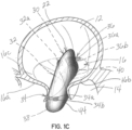
- the selective occlusion device 22 has been fully extruded or extended from the distal end 20a of the catheter 20, and transformed from the collapsed position or condition shown in figure 1A within the catheter 20, to the expanded condition shown in figures 1B and 1C .
- the selective occlusion device 22 comprises a collapsible and expandable frame structure 30.
- the frame structure 30 is comprised of a curved frame number 32 generally extending across the native mitral valve 16 while being supported or stabilized at the native annulus 16c.
- the selective occlusion device 22 is formed in a manner allowing it to be collapsed for delivery as shown in figure 1A , but expanded to the exemplary form shown in figures 1B and 1C .
- the frame structure 30 may be comprised of flexible polymers, metals such as super-elastic or shape memory metals or other materials.
- the selective occlusion device 22 may, for example, expand into a preformed shape through the use of shape memory materials.
- the frame structure 30 may be covered partially or completely by fabrics such as the Dacron, Teflon and/or other covering materials such as used in the manufacture of prosthetic cardiac valves or other implants.
- the frame structure 30 includes a curved frame member 32 which, in this embodiment, and/or other embodiments, extends from one commissure to the other.
- the frame member 32 may instead extend from other portions of the heart tissue generally located at the annulus region.
- the frame structure 30 is supported by respective first and second non-penetrating annulus connectors 34, 36.
- these connectors are configured with respective upper and lower connector elements 34a, 34b and 36a, 36b. These connector elements 34a, 34b and 36a, 36b respectively sandwich or capture annulus tissue therebetween at each commissure.
- the connector elements 34a, 34b and 36a, 36b are each shown as "butterfly-type" connectors that may be slipped or inserted into place with native leaflet tissue sandwiched or secured therebetween. It will be appreciated that other tissue trapping connectors may be used instead, and/or other penetrating or non-penetrating connectors. Non-penetrating connectors are advantageous because they cause no damage that would otherwise occur due to penetrating connectors, and they allow for position adjustment.
- the frame structure 30 further includes first and second membrane support members 40 at opposite ends configured to be located in the left ventricle 14 to support a flexible membrane 44 in a slightly open condition.
- the flexible membrane 44 forms a selective occlusion device that works in conjunction with the native mitral valve leaflets 16a, 16b to control blood flow through the mitral valve 16.
- the flexible membrane 44 acts as a prosthetic heart valve by moving in coordination with the leaflets 16a, 16b as will be described below.
- the selective occlusion device need not have any moving part that moves in conjunction with the leaflets 16a, 16b.
- the flexible membrane 44 is secured at opposite portions of the frame structure 30 to the support members 38, 40 in any suitable manner, such as adhesive, mechanical securement, suturing, fasteners, etc. As further shown, a considerable portion at a lower margin of the flexible membrane 44 is not attached to the frame structure 30.
- the membrane support members 38, 40 are short, curved members and remaining membrane portions at the lower margin of the flexible membrane 44 are not directly attached to any frame portion. This allows the flexible membrane to billow, expand or inflate outward as will be discussed further below during systole to engage with the native leaflets 16a, 16b and prevent regurgitation of blood flow in a reverse direction through the mitral valve 16 when the heart cycle is in systole.
- the flexible membrane 44 may be formed of various types of thin, flexible materials.
- the materials may be natural, synthetic or bioengineered materials. Materials may include valve tissue or pericardial tissue from animals, such as cows and pigs, or other sources. Synthetic materials such as ePTFE, Dacron, Teflon or other materials or combinations of materials may be used to construct the flexible membrane 44. Flexibility of the frame structure 30 together with the flexibility of the flexible membrane 44 provides for operation of the selective occlusion device 22 and the manners contemplated herein, and may also help prevent failure due to fatigue from repeated cycling movement of the selective occlusion device 22 in the heart 10.
- figure 1B shows the flexible membrane 44 removed for a clear view of the frame structure 30, and in this figure the flexible membrane 44 is in broken lines, while in figure 1C the flexible membrane 44 is shown in solid lines, with the heart cycle in systole and the flexible membrane 44 fully engaging the native leaflets 16a, 16b to reduce regurgitation of blood flow through the mitral valve 16.
- the flexible membrane 44 may be sutured to the frame structure 30 using techniques employed by the prosthetic heart valve industry for the manufacture of prosthetic aortic and mitral valves.
- the frame may be made from one or more layers of material, such as super-elastic or shape memory material and the membrane 44 may be suitably secured. One manner may be trapping the flexible membrane 44 between layers of the frame structure 30. To retain the membrane 44 in place, fabric covering(s) (not shown) over a metallic frame may aid in attaching the membrane 44 to the frame structure 30.
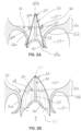
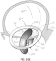
- Figures 2A, 2B and 2C are transverse cross-sections through the selective occlusion device 22 and the mitral valve 16 shown in figures 1A through 1C .
- Figure 2A illustrates the device 22 in a cross section along line 2A-2A of figure 3A
- figure 2B shows the selective occlusion device 22 in cross section along line 2B-2B of figure 3A , with each of these two figures showing the heart cycle in systole.
- Figures 3A and 3B are top views respectively showing the systole and diastole conditions, but not illustrating the hinge 32a that may be provided to assist with folding during delivery.
- Figure 2C is similar to figure 2B but showing the selective occlusion device 22 when the heart cycle is in diastole.
- systole ( figures 2A, 2B and 3A ), which is when the native mitral valve 16 is supposed to fully close to prevent blood flow back into the left atrium 12, the pressurized blood will flow through the open end 45 of the flexible membrane and be prevented from flowing through the closed end 47, at least to any substantial degree.
- a small vent may be provided in the flexible membrane. Because the flexible membrane billows or expands outwardly in the direction of the arrows shown in figure 2B , the native mitral leaflets 16a, 16b will seal against or coapt with the flexible membrane 44 to prevent blood flow regurgitation.
- the arch-shaped membrane support members 38, 40 maintain a separation between lower margins or edges of the flexible membrane 44 to force blood to fill the inside or interior of the membrane 44 during systole through the open end 45, causing the membrane 44 to expand or billow outward so that the membrane 44 fills the gap between the native mitral valve leaflets 16a, 16b.
- the arch-shaped or curved support members 38, 40, and/or other portions of the frame structure 30, may be formed using a central wire and a fabric cover around the wire. Other constructions are possible as well, such as using soft, sponge-like material, and fabrics in conjunction with more structurally supportive material such as metal and/or plastic.
- the filling and emptying of the flexible membrane 44 through the open end 45 can ensure that there is washing or rinsing of the underside of the membrane 44 with each heartbeat to prevent clot formation, and any resulting embolization of clot material.
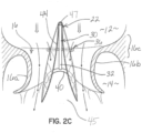
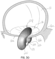
- Figures 4A and 4B are respectively similar to figures 1B and 1C , but illustrate the selective occlusion device 22 isolated from the native mitral valve 16 ( figures 1B and 1C ).
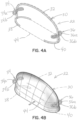
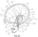
- FIGS 5A through 5D illustrate another embodiment of a selective occlusion device 22a.
- all like reference numerals between the various embodiments and figures refer to like structure and function except to the extent described herein.
- Some reference numerals will have a suffix modification such as a letter (e.g., "22a"), or a prime mark (e.g., 90'), indicating a modification to the like structure which will be discussed and/or apparent from a review of the drawings.
- a suffix modification such as a letter (e.g., "22a")
- a prime mark e.g. 90'
- clips or other anchors may be applied to only one leaflet margin, and more than one clip or anchor may be used.
- mitral valve repair is made with a clip structure 50 having first and second clip elements 50a, 50b movable toward each other from an open condition to a closed position.
- the clip structure 50 is typically applied in a transcatheter procedure using a suitable catheter assembly 52.
- a representative and illustrative clip structure 50 is shown in these figures for clipping together margins of the native leaflets 16a, 16b near a central location of each margin.
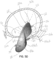
- a selective occlusion device 22a in the form of a frame structure 30a and flexible membrane 44a ( figure 5D ) is introduced through the catheter or catheters 52 in a manner similar to the method described above with respect to the first embodiment.
- the selective occlusion device 22a is guided by the suture, wire or other tensile member 54 affixed and extending from the clip structure 50.
- this embodiment of the device 30a, 44a includes two sections 60, 62.
- This embodiment advantageously utilizes the clip structure 50 as an anchoring mechanism for assisting with securing the device 30a, 44a in place and implanted as a selective occlusion device 22a in the native mitral valve 16.
- the two sections 60, 62 are employed in a manner described above in connection with the single section embodiment of the device 30, 44.
- a modified frame structure 30a is employed to support a modified flexible membrane 44a. More specifically, the flexible membrane 44a includes corresponding sections 44a1 and 44a2. These may be formed from one or more distinct pieces of membrane material.
- third and fourth membrane support members 64, 66 are provided to support the flexible membrane sections 44a1 and 44a2 in manners similar and analogous to the manner that support members 38, 40 support and function in the first illustrative embodiment discussed above.
- An arc-shaped frame member 32 is shown similar to the first embodiment spanning across the native valve 16.
- Vertical support members 65, 67 extend from the frame member 32 and couple with the membrane support members 64, 66.
- the frame member 32 may be eliminated and the vertical members 65, 67 or other structure could be joined together in the central region of the device 22a.
- the suture or wire 54 couples the clip structure 52 to the frame structure 30a, such as by using a crimp element or other securement 68 generally at hinge 32a.
- a crimp element or other securement 68 generally at hinge 32a.
- other securement methods and structures may be used instead to secure the clip structure 50 to the frame structure 30a.
- the clip structure 50 and the frame structure 30a may take other forms than the illustrative forms shown and described herein.
- Use of the clip structure 50 securing the frame structure 30a in addition to the non-penetrating and/or other connectors such as generally at the native annulus 16c provides for an overall secure implant.
- the clip structure 50 and one or more annulus connectors will provide opposing forces that firmly secure the frame structure 30a and flexible membrane 44a generally therebetween.
- the two separate selective occlusion or flow control sections 44a1, 44a2 are separated from each other by the clip structure 50.
- the attachment of the selective occlusion device 22a to the native mitral valve 16 may be a direct connection between the flexible membrane 44a and the native leaflets 16a, 16b (see below).
- Another option is that instead of the single arch-type frame member 32, the two side-by-side sections 60, 62 of the frame structure 30a may be otherwise coupled together near the center of the selective occlusion device 22a to avoid the need for a continuous frame member 32 spanning across the native mitral valve 16.
- the selective occlusion device may be configured as a frame structure and flexible membrane affixed around a continuous perimeter portion of the frame structure.
- Figure 6B illustrates an embodiment of the selective occlusion device 22c slightly different from the embodiment of figure 6A in that the flexible membrane 44a, shown in broken lines, is folded inwardly at the region of the clip structure 50.
- the flexible membrane 44a may be more distinctly attached to the frame members as shown by the broken lines extending upwardly against the vertical frame members 65, 67.
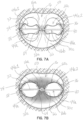
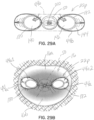
- Figures 7A and 7B are top views illustrating selective occlusion device 22c, such as shown in figure 6B having separate sections 44a1 and 44a2 secured in place and implanted within a native mitral valve 16.
- Figure 7A shows the selective occlusion device 22c when the heart cycle is in diastole
- figure 7B shows the selective occlusion device 22c when the heart cycle is in systole.
- a multi-section apparatus such as with devices 22a, 22b, 22c, is similar to the function of the single section selective occlusion device 22 discussed above in connection with the first illustrative embodiment, except that with the native mitral valve itself separated into two sections by the clip structure 50, the separate flexible membrane sections 44a1 and 44a2 independently function to contract or collapse in diastole ( figure 7A ) and billow, expand or inflate outwardly in systole ( figure 7B ) due to the forceful introduction of blood flow when the heart cycle is in systole.
- the tensile member 54 is shown to have a particular length to connect between the clip structure 50 and the frame member 32, a tensile member or other type of connection of any necessary longer or shorter extent may be used instead.
- the clip structure 50 may be directly affixed to the frame structure 30.
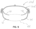
- Figure 9 illustrates a selective occlusion device 22d constructed according to an illustrative embodiment, in which an alternatively configured frame structure 30d is used and coupled with a flexible membrane 44 (shown in broken lines for clarity.
- lower supporting members 70, 72, 74, 76 have a different configuration for guiding the shape of the flexible membrane 44.
- the flexible membrane 44 may be securely attached to the lower supporting members 70, 72, 74, 76 along their entire lengths, or along a portion of their lengths, or not at all if they are otherwise held in place during diastole in a suitable manner.
- the lower margins of the flexible membrane 44 are allowed to billow or expand outwardly and may be detached from the lower supporting members 70, 72, 74, 76 along at least substantial portions to allow this expanding or billowing action to take place.
- the entire frame structure 30d and/or only the lower supporting members 70, 72, 74, 76 may be highly flexible to allow this expansion or billowing action to take place when the heart cycle is in systole, as previously described.
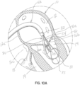
- FIGS 10A , 10B and 10C show another illustrative embodiment in which a transcatheter system 52 is used and, specifically, a clip structure capturing device 80 is used to help secure the selective occlusion device 22a in place.
- a selective occlusion device such as according to the present disclosure to a previously implanted mitral clip structure 50.
- the clip structure 50 may be of any type or configuration. In cases where the clip structure 50 has failed to properly repair the mitral valve 16, or the mitral valve function has degraded over time, despite the clip repair procedure, this embodiment assists with the capturing of the previously implanted clip structure 50 and implantation of a selective occlusion device, such as frame structure 30a and flexible membrane 44a.
- a lasso or suture loop device 80 is deployed from a catheter 82 and captures the clip structure 50 with assistance from a guide device 83.
- the suture, wire or other tensile member 54 that extends upwardly through the mitral valve 16 may be a part of the suture loop device 80 in this embodiment and may then be used as generally described above to guide and securely affix selective occlusion device 22a, to the clip structure 50, as shown in figure 10C .
- the flexible membrane 44a has not been shown in figure 10C .
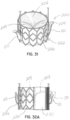
- FIGS 11A and 11B illustrate two additional embodiments of selective occlusion devices 22e, 22f, without showing the flexible membranes, that may be used to prevent blood flow regurgitation through a heart valve such as, by way of example, the mitral valve 16.
- a flexible membrane 44a ( figures 11C through 11E ) may be secured over a frame structure 90, 90' from one end to the other, such as between two non-penetrating annulus connectors or, in other embodiments, penetrating connector portions 92, 94, 92', 94'.
- the flexible membrane 44a is carried on this frame structure 90, 90' and may be secured to the frame members 96, 98 along all or some of the lengths thereof. This can leave a desired portion of the flexible membrane 44a at the lower margin of the frame structures 90, 90' unsecured and able to expand or billow in outward direction during systole, generally as described above in prior described embodiments or in later described embodiments.
- the central frame member connects the annulus connectors 92, 94 and 92', 94' together and arches over and across the mitral valve 16 in a manner similar to frame member 32.
- Suitable configurations of the frame structure 90, 90' may be used, such as any of those previously described, for accommodating one or more clip structures and forming a plurality of separate flexible membrane sections, for example, with one section on each side of a clip structure 50.
- Figures 11A and 11B also show another way of attaching a frame structure generally at the native annulus 16c with one or more holes 106, 108, 110, 112 to engage with a suitable fixation element or anchor 114 ( figure 11D ).
- the embodiment of figure 11D includes two additional fixation holes 116, 118 for receiving fasteners.
- penetrating anchors may be used, such as rivets, T-bars, pledgets, or other fixation elements, although the benefits of non-penetrating connectors in accordance with this disclosure would be desirable, such as for purposes of allowing self-adjustment and reduced tissue damage.
- FIGS 12A and 12B illustrate another illustrative embodiment of a selective occlusion device 22g.
- this apparatus includes at least one rigid occlusion element 120.
- This embodiment is more specifically configured to operate in conjunction with mitral valve leaflets 16a, 16b that have been affixed together at a central location along their margins with a clip structure 50 such as a clip structure previously described. Therefore, two selective occlusion elements 120 are provided for reasons analogous to the two section flexible membrane embodiments described herein.
- the selective occlusion elements 120 are "rigid" in use within the mitral valve 16 in that they are static and need not flex inwardly or outwardly to engage and disengage the native mitral leaflets 16a, 16b during the systole and diastole portions of the heart cycle. Instead, these disk-shaped elements 120 retain their shape and are sized and located in the native mitral valve 16 such that the native mitral leaflets 16a, 16b engage the elements 120 during systole and disengage the elements 120 during diastole. This selective or cyclical interaction is shown in figures 13A and 13B , to be described further below.
- the device 22g shown in figures 12A and 12B includes a frame structure 30e that is configured to extend generally across the native mitral valve 16, with a frame member 32 and hinge 32a as generally described in previous embodiments, along with non-penetrating annulus connectors 34, 36 as also previously described. Further, the clip structure 50 is secured to the frame structure 30e with a crimp element 68 and a suture, wire or other tensile member 54, such as in one of the previously described manners.
- first and second rigid, selective occlusion elements 120 are respectively disposed on opposite sides of the native mitral valve 16 and on opposite sides of the clip structure 50 to selectively include the openings in the native mitral valve 16 formed when the clip structure 50 is affixed to each leaflet 16a, 16b bringing central portions of the two leaflet margins together either in direct contact with each other or in contact with a spacer (not shown) disposed between the movable clip elements.
- the frame structure 30e is formed with it a curved or arch-type frame member 32 configured to extend over the native mitral valve 16 in the left atrium 12.
- the selective occlusion device 22g is shown when the heart cycle is in systole in figures 12A , 12B and 13A .
- the native anterior and posterior mitral valve leaflets 16a, 16b are shown being forced inwardly toward each other. There is no blood leak or regurgitation because the static occlusion elements 120 fill any residual gap between the anterior and posterior leaflets 16a, 16b.
- the elements 120 do not need to be of the depicted shape. Any shape of space filling would be sufficient if the gap between the two leaflets 16a, 16b is filled by the elements 120.
- the best shape could be determined at least partly by studying the shape of the gap between the native mitral valve leaflets 16a, 16b in systole after a clip structure 50 has been applied.
- the optimal shape for the elements 120 for a particular patient anatomy may even be custom manufactured for that patient with rapid manufacturing techniques.
- Advantages of using rigid/static element(s) 120 include their ability to withstand repeated cycling forces perhaps better than a design that relies on one or more moving valve elements that may be more susceptible to fatigue.
- Figure 12B more particularly shows a cut away view of the mitral valve 16 from commissure to commissure.
- the anchors or connectors 34, 36 are shown on each side - both above and below the leaflets 16a, 16b.
- a tensile or other connecting member 54 extends up from the clip attachment component 50 and attaches to the frame member 32 which extends across the valve 16 from commissure to commissure.
- the frame structure 30e can be constructed of a metal material such as stainless steel or Nitinol. Nitinol or other shape memory or super-elastic material may be preferred as this can be collapsed for delivery via a catheter device inside the heart, and then expanded inside the heart for implantation.
- the element(s) 120 may be constructed in a number of ways and have various shapes. They could be composed of a frame of metal such as Nitinol that could be collapsed for catheter delivery.
- the metal frame could be covered by a plastic material or other artificial material like silicone or Teflon or polyurethane. Animal or human pericardium and animal or human heart valve material or any of the materials typically used for heart valve leaflet construction could be used to cover the frame structure 30e. A synthetic material or bioengineered material could also be used to cover the frame structure 30e.
- the inside of the static occlusion elements 120 could be hollow. Or, a bladder or sac could be inside to fill the hollow interior space of the element(s) 120.
- the bladder could be filled with air or any gas or a liquid such as saline, sterile water, blood, antibiotic or antiseptic fluid, polymer or curable fluid material.
- the use of a bladder to fill the inside of the element 120 could eliminate the need or reduce the need for a frame associated with the element 120.
- the selective occlusion device 22g has commissural and leaflet attachments to anchor it in position. It would also be possible to create this apparatus without a leaflet attachment. For example, the attachment could be at the commissures only. It would not be necessary to have a clip structure 50 and a member connected to the frame member 32. In this case there would not need to be two occluding elements 120. A single occlusion element 120 could be used to fill any gap between the two leaflets 16a, 16b. The shape of course would be different - likely an oval surface to extend between the commissures.
- the frame of such an element could be similar to that previously shown and described in connection with the first embodiment or another configuration.
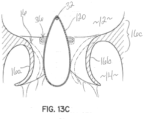
- Figure 12C shows another illustrative embodiment or variation of a selective occlusion device 22h mounted inside the heart to the native mitral valve 16.
- the frame structure 30f is engaged with a clip structure 50 that is attaching the anterior and posterior leaflets 16a, 16b together centrally, e.g., near the A2/P2 junction.
- the frame structure 30f is stabilized by connectors 34, 36 at the commissures and annulus region 16c of the valve 16.
- FIG. 12C The embodiment of figure 12C is similar to that shown in figures 12A and 12B .
- the support frame member 32 is not located above the elements 120 but below the elements 120.
- the support frame member 32 is located above the selective occlusion device and been directed to the left atrium.
- the supporting frame member 32 is biased downward and toward the left ventricle, generally below the mitral valve 16.
- the frame member 32 can be directly connected to the clip structure 50 that attaches the two leaflets 16a, 16b and the frame structure 30f together. This may allow a procedure where the entire device is implanted at one time.
- the clip structure 50, with the selective occlusion device elements 120 coupled to frame structure 30f could be delivered by a catheter (not shown).
- the clip structure 50 (with or without exposing the rest of the device) could be extruded outside the delivery catheter inside the heart 10.
- the clip structure 50 may then be closed on the native mitral valve anterior and posterior leaflets 16a, 16b.
- the remainder of the selective occlusion device 22h could be then released from the delivery catheter - placing the entire device in position. This may simplify the procedure to one step.
- the frame structure has been above the clip structure 50, and in this embodiment, the frame structure 30f is below. It is also possible to have both an upper and a lower support frame structure (such as by combining two arc-shaped supports in one device). It would also be possible to join upper and lower arc support or frame members, so the support or frame structure is a complete loop or circle. This may provide further structural strength to the system.
- Figure 12D is a side elevational view schematically illustrating another illustrative embodiment of a selective occlusion device 22i including first and second rigid or static selective occlusion elements 120 coupled with a frame structure 30g.
- the rigid selective occlusion elements 120 are directly coupled to the frame structure 30g, which may be a frame member 32 coupled with the clip structure 50.
- the clip structure 50 may directly couple respective margins of the anterior and posterior mitral leaflets 16a, 16b, or may couple these leaflet margins together against an intermediate spacer (not shown).
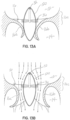
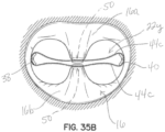
- FIGs 13A and 13B schematically illustrate, in cross section, the functioning of the rigid, selective occlusion elements 120 shown in figures 12A through 12D .
- the native mitral leaflets 16a, 16b will close against the rigid selective occlusion elements 120 to provide a fluid seal against regurgitation of blood flow.
- the mitral valve leaflets 16a, 16b will spread apart and disengage from the rigid selective occlusion elements 120 to allow blood flow from the left atrium 12 into the left ventricle 14 between the rigid selective occlusion elements 120 and the respective native leaflets 16a, 16b.
- the one or more elements 120 fill any gap between the anterior and posterior leaflets 16a, 16b.
- mitral regurgitation occurs due to failure of complete leaflet coaptation, the leaflets 16a, 16b are frequently pulled apart from each other in the plane of the valve 16 (here left-right).
- the situation may become more complex because the leaflets 16a, 16b tend to be pulled down into the ventricle 14 as well as apart from each other as mitral regurgitation becomes more severe over time. So, an up/down gap may also occur with one leaflet 16a or 16b sitting at a higher plane than the other leaflet 16a, 16b.
- a convexly curved outer surface of the element(s) 120 is that this surface can be shaped to adapt to a wide variety of defects that may occur between the anterior and posterior leaflets 16a, 16b.
- An outer, convexly curved surface of the element(s) 120 can accommodate leaflet gaps that are in the plane of the valve 16 (left right in the figure) and perpendicular to the plane of the valve 16 (up and down in the figure).
- the selective occlusion device 22g is symmetric on each side.
- the elements 120 could also be constructed so that they are asymmetrical, i.e., not identical on opposite sides.
- the posterior leaflet 16b may be more retracted into the left ventricle 14 than the anterior leaflet 16a. It may be useful to have adjustments in the element 120 on the side facing the posterior leaflet 16b to fill the gap left by a retracted posterior leaflet 16b.
- the element 120 may be constructed to be more prominent on the side of the element 120 adjacent to the posterior leaflet 16b than on the side adjacent or facing the anterior leaflet 16a.
- One or more elements 120 may be adjustable in shape, such as by an adjustable level of inflation to a hollow interior of the element 120 or other method, to accommodate any need to fill a gap between the leaflets 16a, 16b that would otherwise cause regurgitation.
- Custom made or custom size elements 120 could also be made depending on the shape of the gap.
- a gap could be determined by echocardiography or CT and appropriately sized and shaped filling elements 120 could be selected based on measurements obtained with imaging.
- the valve defect that needs repair may be more shaped as a cylinder and a cylinder or pyramid-cylinder shape may be better to stop blood regurgitation than a lens or disc shape for the element(s) 120.
- the margins of the element(s) 120 facing the oncoming flow of blood from the left atrium 12 has a tapering surface. This will allow the blood to flow smoothly into the left ventricle and avoid blood damage or hemolysis and to promote complete and unimpeded filling of the left ventricle 14.
- the edge of the element(s) 120 inside the left ventricle 14 also demonstrates a taper similar to the inflow region of the element(s) 120.
- the rigid selective occlusion element(s) 120 may be formed in a fluid efficient manner, such as a teardrop shape or other hemodynamic shape to prevent undesirable blood flow patterns and damage or hemolysis as the blood flows past the elements 120 in between the element 120 and the respective mitral leaflets 16a, 16b.
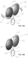
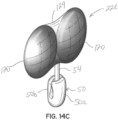
- FIGs 14A, 14B and 14C illustrate additional embodiments of selective occlusion devices 22j, 22k, 22l that utilize rigid or static selective occlusion elements 120. These elements 120 function as discussed above in connection with figures 12A through 12D and figures 13A, 13B .
- the rigid or static selective occlusion elements 120 are coupled to a frame structure 30h that is secured along top margins of the elements 120.
- respective commissure connectors 126, 128 are provided that include connecting elements which operate the same as the butterfly type elements previously described by sandwiching mitral tissue or other heart tissue therebetween. Additional securement is provided by the clip structure 50 and a suitable tensile element or other connector 54, such as also previously described.
- Figure 14B illustrates an embodiment of a selective occlusion device 22k in the form of rigid or static elements 120 that are again generally disc shaped and secured together by a frame member 32', a tensile element or connector 54 and a connected a clip structure 50.
- Figure 14C illustrates an embodiment of a selective occlusion device 22l in which the rigid selective occlusion elements 120 are secured together by fabric or other structure 129, and further secured through a tensile member or other connector 54 to a clip structure 50 which secures the selective occlusion device 22l to the native mitral valve 16 through a clipping action as previously described.
- FIGS 15A through 15E illustrate another embodiment of a of a selective occlusion device 22m including a flexible membrane 44a and a frame structure 30i.
- the flexible membrane 44a is secured to frame structure 30i that is also preferably flexible for reasons such as previously described.
- This embodiment is similar to previous embodiments utilizing flexible membranes 44a in conjunction with a mitral valve clip structure 50, but includes a central reinforced area such as a fabric area 130 allowing the native leaflet margin tissue to be a clipped against the reinforced fabric area 130 directly.
- the clip structure 50 is shown in broken lines in figure 15E .
- the native mitral tissue is not directly contacting abutting native mitral tissue but instead contacts and is secured against the reinforced central fabric area 130 of the flexible membrane 44a.
- This fabric or other reinforcing material 130 may, for example, be useful in situations where the remainder of the flexible membrane is formed from more delicate material such as biologic material.
- Annulus connectors 132, 134 are provided and rest against an upper portion of the annulus 16c as generally shown in other figures, such that the clip structure 50 (not shown in this embodiment) secures the selective occlusion device 22m to the reinforced, central area 130 from below, and the annulus connectors 132, 134 secure the selective occlusion device 22m from above by bearing against or otherwise coupling to the native annulus 16c.
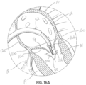
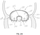
- FIGS 16A through 16D illustrate another illustrative embodiment of a transcatheter delivered selective occlusion device 22n combined with a clip structure 50.
- the clip structure 50 is used to affix a lower central margin portion of one leaflet 16a to a lower central margin portion of the opposing leaflet 16b, generally as previously described. Again, this clipping action may be for purposes of clipping the anterior leaflet 16a directly in contact with the posterior leaflet 16b at the central location, or clipping the anterior and posterior leaflets 16a, 16b against an intermediate spacer.
- the selective occlusion device is coupled with the clip structure 50 delivered through one or more catheters 52.
- the catheter assembly 52 is delivered transeptally into the left atrium 12 and downwardly through the native mitral valve 16 although other approaches may be used instead in the various embodiments.
- the clip structure 50 is extruded from the catheter assembly distal end and, in the open condition shown in figure 16A captures the leaflet margin portions as shown in figure 16B and is actuated to move one or both clip elements 50a, 50b together into the position shown in figure 16C to secure the central leaflet margin portions together.
- the remaining portion of the selective occlusion device 22n is then extruded from the distal end of the catheter assembly 52 as shown in figure 16C .
- the selective occlusion device 22n which may be, as illustrative examples, of the type shown in figure 16D or any of the types otherwise shown and described herein, or even other configurations contemplated hereby, self-expands into the mitral valve location.
- Operation of the selective occlusion device 22n may be generally as described herein, and securement of the device 22n occurs generally between the clip structure 50 and respective annulus connectors 132, 134.
- the annulus connectors 132, 134 provide a downward force for securing the device 22n generally at the annulus 16c, while the clip structure 50 provides an upward force to generally secure the selective occlusion device 22n therebetween in place in the native mitral valve 16.
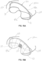
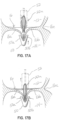
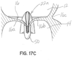
- FIGs 17A through 17C illustrate an embodiment of an apparatus for transcatheter delivery and implantation.
- the clip structure 50 is delivered below the mitral valve 50 generally as previously described, and the selective occlusion device 22n is delivered to a location above the native mitral valve 16.
- the selective occlusion device 22n is inserted into the mitral valve 16 and between the native leaflets 16a, 16b, and also between the clip elements as shown in the method proceeding from figure 17A to 17B .
- the clip elements is moved toward the other clip element to clip or clamp the leaflet margins together, as previously described, and also to clamp a lower central portion of the selective occlusion device 22n and, particularly, the flexible membrane 44a in this embodiment, such that the leaflet margins are secured together at the same time as the selective occlusion device 22n is secured and implanted in place within the native mitral valve 16.
- the selective occlusion device 22n is fully extruded from the catheter assembly, whereupon it self-expands into position in the native mitral valve 16 and functions as otherwise generally discussed herein.
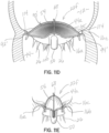
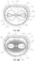
- figures 18A and 18B illustrate the diastole and systole portions, respectively, of the heart cycle with the apparatus secured in place as described in connection with figures 17A through 17C .
- FIG 18A during diastole, blood flow is allowed between the native mitral leaflets 16a, 16b and the flexible membrane 44a, while in systole the flexible membrane 44a, in each section, fills with blood and thereby expands or inflates as the mitral leaflets 16a, 16b move toward one another and against the flexible membrane 44a to form a fluid seal preventing regurgitation of blood flow from the left ventricle 14 into the left atrium 12 of the heart 10.
- Figure 19 is an anatomical view from above the native mitral valve 16 with the selective occlusion device 22n superimposed to show another representation for the configuration in which the selective occlusion device 22n is curved and flexes in accordance with the natural curvature of the mitral valve 16.
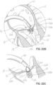
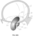
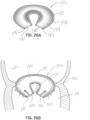
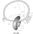
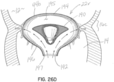
- Figures 20, 21A, 21B and 21C illustrate another embodiment for a selective occlusion device 22o and apparatus (combining the device 22o with a clip structure 50), in which the selective occlusion device 22o is configured generally as a two section device, but with the sections in fluid communication as best shown in figure 21A .
- a clip structure 50 is secured to the selective occlusion device 22o at a position between respective open ends 140, 142 of the sections.
- the clip structure 50 is used in the same manner as previously described.
- the flexible membrane 44b is supported by a flexible but strong frame structure 143, which may be formed in any manner contemplated herein, such as for allowing transcatheter delivery and implantation.
- the open ends 140, 142 are defined by hoop or ring portions 145, 147 of the frame structure 143.
- the hollow interior 144 of a flexible membrane 44b receives blood flow in the systole portion of the heart cycle and fluid communication between the two openings 140, 142 ensures better rinsing or washing during the heart cycle to reduce the chances of blood clots.
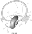
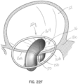
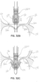
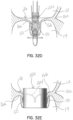
- FIGs 22A through 22D illustrate another embodiment of an apparatus for transcatheter delivery and implantation of a clip structure 50 coupled with a selective occlusion device 22p.
- the clip structure 50 clips the native mitral leaflets 16a, 16b against a central or intermediate spacer 150, instead of directly into contact with each other.
- the procedure is generally shown in figures 22A through 22C in which the clip structure 50 is first extruded from the transeptally directed catheter assembly 52 generally at a location below the mitral leaflets 16a, 16b.
- the leaflets 16a, 16b are captured against the intermediate spacer 150, as shown in figure 22B .
- the leaflets 16a, 16b are secured firmly against the spacer 150 as shown in figure 22C by moving at least one of the clip elements 50a, 50b toward the other. In this embodiment, each clip element 50a, 50b is moved toward the central or intermediate spacer 150 to clamp leaflet tissue against the spacer 150.
- the selective occlusion device 22p in this illustrative embodiment, is already secured to the clip structure 50 when it is extruded from the catheter assembly 52 as illustrated in figure 22C whereupon the selective occlusion device 22p self-expands into the implanted condition shown in figure 22D .
- the selective occlusion device 22p may be extruded and implanted as a separate component, as well as coupled to the clip structure 50 in a suitable manner, instead of being extruded in an already assembled form from the catheter or catheters 52.
- Figure 22E illustrates another embodiment, similar to that shown in figure 22D , but further illustrating respective annulus connectors 154, 156 as part of the selective occlusion device 22p in the form of frame members that bear against heart tissue generally at the annulus 16c in the left atrium 12 and, additionally or optionally, frame members or connectors 158, 160 (shown in broken lines) coupled with the selective occlusion device 22p and located in the left atrium 12 abutting the annulus 16c from below.
- Use of both sets of annulus connectors 154, 156, 158, 160 results in sandwiching the heart tissue therebetween for better securement.
- Figure 22F illustrates another embodiment of a device 22q, similar to figure 22E , but illustrating a single annular connector 164 generally encircling the native mitral valve 16 formed as part of the selective occlusion device and anchoring the selective occlusion device 22q in the native mitral valve 16 securely, preventing rocking in any direction but allowing flexibility.
- the frame members may be formed of any desired material, such as flexible wire-like materials formed from polymers and/or flexible metals including super-elastic or shape memory materials. This can help achieve overall goals of the embodiments of flexibility for collapsed delivery and improved operation during implanted use, as well as resistance against failure due to fatigue in this application involving continuous cycling in the heart.
- FIG 22G illustrates another embodiment of a device 22r.
- the selective occlusion device 22r may be as described in connection with any other embodiment, but for illustrative purposes, is shown with a hollow flexible membrane 44b, while the frame structure has been modified as shown.
- the frame structure includes a generally annular frame member 170 such as described and shown in connection with figure 22F , but including raised portions 170a, 170b relative to other portions.
- the raised portions 170a, 170b are configured to be located adjacent and above the commissures of the native mitral valve 16 and are connected with a central frame member 32 extending generally across the native mitral valve 16 and formed as part of the selective occlusion device 22r such as with another connecting frame member 172.
- Such frame members at the annulus may be above the annulus, below the annulus, or frame members/connectors may be above and below the annulus to sandwich tissue therebetween.
- Figures 23A and 23B schematically illustrate a selective occlusion device 22s coupled with a central clip 50 including a spacer 150 implanted in a mitral valve 16.
- Figure 23A illustrates the device 22s and the mitral valve 16 when the heart cycle is in systole
- figure 23B illustrates the mitral valve 16 and the selective occlusion device 22s when the heart is in diastole.
- the frame structure includes respective hoops or rings 180, 182 as shown in solid lines in figure 23A and broken lines in figure 23B . These define the openings 140, 142.
- a benefit of this frame configuration is that the frame will not contact the commissures during repeated heart cycling.
- the device like other embodiments allows blood flow from the left atrium to the left ventricle in diastole but prevents blood flow during systole.
- Figure 24 is a cross-sectional view schematically illustrating the mitral valve 16 and the implanted selective occlusion device 22s, coupled with a central clip structure 50 such as at a coupling 183.
- the selective occlusion device 22s is of a type with a hollow interior 144 having two fluid communicating sections 184, 186 and respective first and second openings 140, 142 and a closed end 188. Fluid communication between sections 184, 186 allows for better rinsing and washing action and reduced chance of clotting.
- FIGS 25A and 25B are schematic views of a selective occlusion device 22t, 22t' including a flexible membrane 44b, 44b' with figures 25A and 25B showing the selective occlusion devices 22t, 22t' when the heart cycle is in systole.
- the difference between the two devices 22t, 22t' is that the flexible membrane 44b' is integrated into the spacer 150 of the clip structure 50, while the flexible membrane 44b is not.
- Flexible membrane 44b and/or another portion, such as a frame portion, of device 22t may be otherwise coupled to clip structure 50 such as in the manner shown in figure 24 or another suitable manner.
- FIGs 26A, 26B and 26C schematically illustrate another illustrative embodiment of an apparatus including a central clip structure 50 ( figure 26B ) and a selective occlusion device 22u.
- the selective occlusion device 22u is a hollow fluid communicating structure having a flexible membrane 44b and allowing blood flow into the hollow interior 144 defined by the flexible membrane 44b in systole, as shown in figure 26B and 26C .
- the flexible membrane 44b collapses inwardly, as previously shown and described, to allow blood flow past the selective occlusion device 22u and between the native mitral leaflets 16a, 16b from the left atrium 12 into the left ventricle 14.
- openings 140, 142 and shape of the device 22u force blood flow, in systole, toward the commissure regions as shown by the arrows. These forces help retain the device 22u in place, in addition to any other securement such as the clip structure 50. In this way, rocking of the device 22u may be reduced and the device 22u can be more stable during implantation and use.
- These inlets 140, 142 are angled acutely away from the central clip structure 50 as shown in figure 26B .
- Figure 26D illustrates another embodiment of a selective occlusion device 22v in which a suitable baffle structure 190 is provided within the selective occlusion device 22v for directing blood flow outwardly as shown by the arrows toward the connecting locations between the device 22v and the mitral annulus 16c. This helps to produce securement force and stabilization of the device 22v in the implanted condition.
- a single opening 192 is provided for in flow during systole and the device 22v includes a closed end 194 and a hollow interior 195, such that the device 22v fills with blood during systole and collapses to expel the blood during diastole as previously shown and described.
- a frame structure 196 is provided to support a flexible membrane 44b, generally as previously described, except that the frame structure is shaped and configured differently so as to form the single opening 192 defined by a hoop or ring frame member 197. It will be appreciated that the shapes and configurations of these structures may be modified from those shown in these illustrative examples.
- Figure 26E is an embodiment of a device 22w that may be configured as previous embodiments have been described, in terms of the selective occlusion device 22w, but which includes a generally annular or circular frame 200 structure that is a flat element for securing the apparatus in place in the mitral valve 16.
- the frame structure 200 is shown to rest and/or be secured in the left atrium 12 abutting against heart tissue generally proximate the mitral annulus 16c.
- an additional lower support may be provided to sandwich heart tissue therebetween.
- FIGS 27A through 27C illustrate another embodiment of a selective occlusion device 22x which may be constructed in accordance with previous described embodiments, but including at least one small vent 202 opposite to the two openings 140, 142 of the flexible membrane 44b.
- the vent 202 is not large enough to result in any significant regurgitation or leakage of blood in systole. To the extent that the vent 202 does not allow any significant regurgitation of blood, this end of the flexible membrane is closed while the opposite end includes at least one and, in this embodiment two openings 140, 142. Otherwise, this embodiment of the flexible membrane 44b operates and functions for purposes and in ways as previously shown and described.
- One or more vents 202 may, for example, provide a pressure relief to reduce the forces against the device 22x during high pressure systole portions of the heart cycle.
- Figures 28A through 28C illustrate another embodiment of an apparatus comprised of a central clip structure 50 and the previously described selective occlusion device 22p.
- the clip structure 50 includes a central gripping structure 210 which may have tines or other knurled, roughened or frictional surfaces. This will assist with clamping and retaining mitral leaflet margin tissue between the respective clip elements 50a, 50b and the selective occlusion device 22p.
- the clip structure 50 is secured to the selective occlusion device 22p, such as via the central gripping element 210.
- Figures 28B and 28C further illustrate that the selective occlusion device 22p operates in the same manner, for example, as described above with fluid communication between two generally adjacent openings 140, 142 for increased washing and rinsing.
- FIGS 29A, 29B and 30 illustrate the apparatus shown in figures 28A through 28C in operation after being implanted in the mitral valve 16.
- blood enters the selective occlusion device 22p through the open ends 140, 142 and fills the interior 144 defined by the flexible membrane 44b, whereupon the flexible membrane 44b expands or inflates to engage in contact with the native mitral leaflets 16a, 16b forming a fluid seal that prevents regurgitation of blood flow during systole ( figures 29A and 29B ).
- FIG 29B illustrates the anatomy of the mitral valve 16 further shown and the native leaflet tissue contacting the outside surfaces of the flexible membrane 44b during systole.
- Figure 31 illustrates another embodiment showing an expandable prosthetic heart valve 220, which may be comprised of a generally cylindrical outer or peripheral frame structure 222 and coupled with interior prosthetic leaflets 224 that open and close to control blood flow therethrough.
- an expandable prosthetic heart valve 220 which may be comprised of a generally cylindrical outer or peripheral frame structure 222 and coupled with interior prosthetic leaflets 224 that open and close to control blood flow therethrough.
- a selective occlusion device which have at least one movable valve element (e.g., the flexible membrane that operates in conjunction with a native mitral leaflet), in that this prosthetic heart valve 220 does not operate in conjunction with the native leaflet to control blood flow. Instead, the prosthetic leaflets 224 control blood flow through the prosthetic valve 220.
- FIG. 32A is a side elevational view partially fragmented to show the internal stent structure 226 exposed underneath an outer covering 230, which may be natural, synthetic, biologic, bioengineered, or any other suitable medical grade material useful for cardiac devices of this type.
- FIGs 32B through 32E illustrate the succession of steps used to implant the prosthetic valve 220 of figures 31 and 32A .
- this apparatus may be implanted through a transcatheter procedure, or a more invasive procedures such as a surgical procedure or keyhole type or other less invasive procedure.
- the collapsed or folded apparatus 220 is inserted between the mitral valve leaflets 16a, 16b as shown in figure 32B , the clip structures 50 are used to capture the lower margins of the mitral leaflets 16a, 16b ( figure 32C ) and clamp them as shown in figure 32D .
- the expandable prosthetic heart valve 220 is then expanded against the native mitral leaflets 16a, 16b as shown in figure 32E to secure the implanted prosthetic heart valve 220 in place within the native mitral valve 16.
- the prosthetic leaflets 224 then open and close, respectively during diastole and systole to allow and prevent the flow of blood through the prosthetic heart valve 220.
- Figure 33 illustrates another embodiment, similar to the previous embodiment shown in figure 32 , but adding an upper flange element 236 that helps secure the prosthetic heart valve 220 by stabilizing the heart valve 220 within the left atrium 12.
- the flange 236 is mounted above the native mitral valve 16.
- the flange 236 may abut against heart tissue in the lower portion of the left atrium 12.
- Figure 34A is a side elevational view of the prosthetic heart valve 220 shown in figure 33 .
- Figure 34B is an illustration of the prosthetic heart valve 220 shown secured in place within the native mitral valve 16.
- FIGs 35A and 35B show another embodiment of a selective occlusion device 22y mounted in a native mitral valve 16, as viewed in cross section.
- This embodiment includes a flexible membrane 44c with an open end facing the left ventricle 14, as in other embodiments, and receiving blood flow from below when the heart cycle is in systole ( figure 35A ).
- the flexible membrane 44c expands against the native leaflets 16a, 16b to reduce regurgitation as previously discussed.
- the flexible membrane collapses and expels the blood therein ( figure 35B ). Blood then travels in the reverse direction, generally, through the mitral valve 16 by flowing between the native leaflets 16a, 16b and outer surfaces of the collapsed membrane 44c.
- a difference between this embodiment and others is that multiple clip structures 50 are used to secure the selective occlusion device 22y directly to the leaflets 16a, 16b.
- the leaflets 16a, 16b are not clipped to each other. It will be appreciated that even further clip structures 50 may be used in this embodiment as well as others.
- a clip structure 50 secures one side of the flexible membrane 44c to the anterior leaflet 16a and another clip structure 50 secures the flexible membrane 44c to the posterior leaflet 16b.
Landscapes
- Health & Medical Sciences (AREA)
- Cardiology (AREA)
- Engineering & Computer Science (AREA)
- Biomedical Technology (AREA)
- Heart & Thoracic Surgery (AREA)
- Transplantation (AREA)
- Oral & Maxillofacial Surgery (AREA)
- Vascular Medicine (AREA)
- Life Sciences & Earth Sciences (AREA)
- Animal Behavior & Ethology (AREA)
- General Health & Medical Sciences (AREA)
- Public Health (AREA)
- Veterinary Medicine (AREA)
- Prostheses (AREA)
Claims (6)
- Vorrichtung zur Behandlung von Blutregurgitation durch eine native Herzklappe, die ein erstes und ein zweites natives Segel aufweist, wobei die Vorrichtung Folgendes umfasst:eine selektive Okklusionsvorrichtung (22, 22a), die so bemessen und ausgestaltet ist, dass sie in die native Herzklappe implantiert wird und selektiv mit dem ersten und/oder dem zweiten nativen Segel wirkt, um Blutströmung durch die native Herzklappe zu gestatten, wenn sich der Herzzyklus in Diastole befindet, und eine Blutregurgitation durch die native Herzklappe zu reduzieren, wenn sich der Herzzyklus in Systole befindet, eine Clipstruktur (50), die mit der selektiven Okklusionsvorrichtung (22, 22a) gekoppelt ist, wobei die Clipstruktur (50) dazu ausgestaltet ist, an einem Rand des ersten und/oder des zweiten nativen Segels befestigt zu werden, um die selektive Okklusionsvorrichtung (22, 22a) an der nativen Herzklappe zu befestigen,wobei die selektive Okklusionsvorrichtung (22, 22a) eine Herzklappenprothese umfasst, die ein bewegliches Klappenelement aufweist, das dazu ausgelegt ist, die Blutströmung durch die native Herzklappe selektiv zu steuern, und wobei das bewegliche Klappenelement eine flexible Membran (44) umfasst, die dazu ausgelegt ist, das erste und das zweite native Segel der nativen Herzklappe in Eingriff zu nehmen, wenn sich der Herzzyklus in der Systole befindet, und aus dem ersten und dem zweiten nativen Segel auszurücken, wenn sich der Herzzyklus in Diastole befindet.
- Vorrichtung nach Anspruch 1, wobei die Clipstruktur einen Clip aufweist, der aus einem Paar Clipelementen besteht, wobei mindestens eines der Clipelemente zwischen einer offenen und einer geschlossenen Position beweglich ist und die Clipelemente in der geschlossenen Position natives Segelgewebe dazwischen erfassen.
- Vorrichtung nach Anspruch 1, wobei die Clipstruktur ferner Folgendes umfasst:
einen ersten und einen zweiten Clip, die jeweils ein Paar Clipelemente aufweisen, wobei mindestens eines der Clipelemente jedes Paars zwischen einer offenen und einer geschlossenen Position bezüglich des anderen Clipelements jedes Paars beweglich ist, und wobei der erste Clip dazu ausgestaltet ist, das erste native Segel an der selektiven Okklusionsvorrichtung anzubringen, und der zweite Clip dazu ausgestaltet ist, das zweite native Segel an der selektiven Okklusionsvorrichtung anzubringen. - Vorrichtung nach Anspruch 1, ferner Folgendes umfassend:eine Rahmenstruktur, die mit der Clipstruktur gekoppelt ist, undeinen nicht penetrierenden Anulusverbinder, der mit der Rahmenstruktur gekoppelt ist, wobei der Anulusverbinder dazu ausgelegt ist, mit Herzgewebe in Eingriff zu kommen, ohne das Gewebe zu penetrieren,wobei die Rahmenstruktur dazu ausgestaltet ist, sich allgemein zwischen den Kommissuren über die native Herzklappe zu erstrecken, und die selektive Okklusionsvorrichtung allgemein zwischen der Clipstruktur und dem Anulusverbinder an Ort und Stelle befestigt ist.
- Vorrichtung nach Anspruch 1, wobei die flexible Membran ein geschlossenes Ende und ein offenes Ende aufweist, wobei das offene Ende Blutströmung empfängt, wenn sich der Herzzyklus in Systole befindet, um die Membran in Eingriff mit dem ersten und dem zweiten nativen Segel zu expandieren, und das offene Ende schließt, wenn sich der Herzzyklus in Diastole befindet, um Blutströmung zwischen der Membran und dem ersten und dem zweiten nativen Segel zu gestatten.
- Vorrichtung nach Anspruch 1, wobei die selektive Okklusionsvorrichtung ferner Folgendes umfasst:
ein erstes und ein zweites selektives Okklusionselement, die so bemessen und ausgestaltet sind, dass sie in die native Herzklappe implantiert werden, so dass das erste und/oder das zweite native Segel das erste und das zweite selektive Okklusionselement in Eingriff nehmen, wenn sich der Herzzyklus in der Systole befindet, um die Blutströmung durch die native Herzklappe zu reduzieren, und das erste und/oder das zweite native Segel aus dem ersten und dem zweiten selektiven Okklusionselement ausrückt, wenn sich der Herzzyklus in Diastole befindet, um Blutströmung durch die native Herzklappe zu gestatten.
Priority Applications (1)
| Application Number | Priority Date | Filing Date | Title |
|---|---|---|---|
| EP24216019.0A EP4541293A3 (de) | 2018-02-08 | 2019-02-08 | Vorrichtung zur behandlung von blutflussregurgitation durch eine native herzklappe |
Applications Claiming Priority (3)
| Application Number | Priority Date | Filing Date | Title |
|---|---|---|---|
| US201862627894P | 2018-02-08 | 2018-02-08 | |
| US201862671077P | 2018-05-14 | 2018-05-14 | |
| PCT/US2019/017283 WO2019157331A1 (en) | 2018-02-08 | 2019-02-08 | Methods, apparatus and devices to treat heart valves |
Related Child Applications (1)
| Application Number | Title | Priority Date | Filing Date |
|---|---|---|---|
| EP24216019.0A Division EP4541293A3 (de) | 2018-02-08 | 2019-02-08 | Vorrichtung zur behandlung von blutflussregurgitation durch eine native herzklappe |
Publications (3)
| Publication Number | Publication Date |
|---|---|
| EP3749255A1 EP3749255A1 (de) | 2020-12-16 |
| EP3749255A4 EP3749255A4 (de) | 2022-02-23 |
| EP3749255B1 true EP3749255B1 (de) | 2024-12-04 |
Family
ID=67549657
Family Applications (2)
| Application Number | Title | Priority Date | Filing Date |
|---|---|---|---|
| EP19751030.8A Active EP3749255B1 (de) | 2018-02-08 | 2019-02-08 | Vorrichtung zur behandlung von herzklappenregurgitation bei einer natürlichen herzklappe |
| EP24216019.0A Pending EP4541293A3 (de) | 2018-02-08 | 2019-02-08 | Vorrichtung zur behandlung von blutflussregurgitation durch eine native herzklappe |
Family Applications After (1)
| Application Number | Title | Priority Date | Filing Date |
|---|---|---|---|
| EP24216019.0A Pending EP4541293A3 (de) | 2018-02-08 | 2019-02-08 | Vorrichtung zur behandlung von blutflussregurgitation durch eine native herzklappe |
Country Status (4)
| Country | Link |
|---|---|
| US (4) | US10912646B2 (de) |
| EP (2) | EP3749255B1 (de) |
| CN (1) | CN111902103B (de) |
| WO (1) | WO2019157331A1 (de) |
Families Citing this family (45)
| Publication number | Priority date | Publication date | Assignee | Title |
|---|---|---|---|---|
| US10517719B2 (en) | 2008-12-22 | 2019-12-31 | Valtech Cardio, Ltd. | Implantation of repair devices in the heart |
| WO2012176195A2 (en) | 2011-06-23 | 2012-12-27 | Valtech Cardio, Ltd. | Closure element for use with annuloplasty structure |
| US8449599B2 (en) | 2009-12-04 | 2013-05-28 | Edwards Lifesciences Corporation | Prosthetic valve for replacing mitral valve |
| US9439763B2 (en) | 2013-02-04 | 2016-09-13 | Edwards Lifesciences Corporation | Prosthetic valve for replacing mitral valve |
| US9622863B2 (en) | 2013-11-22 | 2017-04-18 | Edwards Lifesciences Corporation | Aortic insufficiency repair device and method |
| CN115721454A (zh) | 2014-12-04 | 2023-03-03 | 爱德华兹生命科学公司 | 用于修复心脏瓣膜的经皮夹具 |
| EP4591832A3 (de) | 2015-05-14 | 2025-10-22 | Edwards Lifesciences Corporation | Herzklappenverschlussvorrichtungen und freisetzungsvorrichtungen dafür |
| US11219746B2 (en) | 2016-03-21 | 2022-01-11 | Edwards Lifesciences Corporation | Multi-direction steerable handles for steering catheters |
| US10799675B2 (en) | 2016-03-21 | 2020-10-13 | Edwards Lifesciences Corporation | Cam controlled multi-direction steerable handles |
| US10973638B2 (en) | 2016-07-07 | 2021-04-13 | Edwards Lifesciences Corporation | Device and method for treating vascular insufficiency |
| US10653862B2 (en) | 2016-11-07 | 2020-05-19 | Edwards Lifesciences Corporation | Apparatus for the introduction and manipulation of multiple telescoping catheters |
| US10905554B2 (en) | 2017-01-05 | 2021-02-02 | Edwards Lifesciences Corporation | Heart valve coaptation device |
| ES2991801T3 (es) | 2017-04-18 | 2024-12-04 | Edwards Lifesciences Corp | Dispositivos de sellado de válvula cardíaca y dispositivos de suministro para los mismos |
| US11224511B2 (en) | 2017-04-18 | 2022-01-18 | Edwards Lifesciences Corporation | Heart valve sealing devices and delivery devices therefor |
| US10799312B2 (en) | 2017-04-28 | 2020-10-13 | Edwards Lifesciences Corporation | Medical device stabilizing apparatus and method of use |
| US10959846B2 (en) | 2017-05-10 | 2021-03-30 | Edwards Lifesciences Corporation | Mitral valve spacer device |
| WO2019023138A1 (en) | 2017-07-24 | 2019-01-31 | Emory University | DEVICES AND SYSTEMS FOR ENHANCING CARDIAC VALVE LEAVES |
| US11051940B2 (en) | 2017-09-07 | 2021-07-06 | Edwards Lifesciences Corporation | Prosthetic spacer device for heart valve |
| US11065117B2 (en) | 2017-09-08 | 2021-07-20 | Edwards Lifesciences Corporation | Axisymmetric adjustable device for treating mitral regurgitation |
| US11110251B2 (en) | 2017-09-19 | 2021-09-07 | Edwards Lifesciences Corporation | Multi-direction steerable handles for steering catheters |
| US10231837B1 (en) | 2018-01-09 | 2019-03-19 | Edwards Lifesciences Corporation | Native valve repair devices and procedures |
| ES2999260T3 (en) | 2018-01-09 | 2025-02-25 | Edwards Lifesciences Corp | Native valve repair devices |
| US10111751B1 (en) | 2018-01-09 | 2018-10-30 | Edwards Lifesciences Corporation | Native valve repair devices and procedures |
| US10123873B1 (en) | 2018-01-09 | 2018-11-13 | Edwards Lifesciences Corporation | Native valve repair devices and procedures |
| EP3749255B1 (de) | 2018-02-08 | 2024-12-04 | Invalve Therapeutics, Inc. | Vorrichtung zur behandlung von herzklappenregurgitation bei einer natürlichen herzklappe |
| US20200390552A1 (en) * | 2018-07-10 | 2020-12-17 | Syntach Ag | Implantable cardiac valve improvement device, system and procedure |
| US10945844B2 (en) | 2018-10-10 | 2021-03-16 | Edwards Lifesciences Corporation | Heart valve sealing devices and delivery devices therefor |
| CN113226223A (zh) | 2018-11-20 | 2021-08-06 | 爱德华兹生命科学公司 | 用于将装置递送至天然心脏瓣膜的部署工具和方法 |
| CA3118988A1 (en) | 2018-11-21 | 2020-05-28 | Edwards Lifesciences Corporation | Heart valve sealing devices, delivery devices therefor, and retrieval devices |
| EP3886688B1 (de) | 2018-11-29 | 2024-08-07 | Edwards Lifesciences Corporation | Katheterisierungsvorrichtung |
| DK3923867T3 (da) | 2019-02-14 | 2023-12-04 | Edwards Lifesciences Corp | Hjerteklapforseglingsindretninger og leveringsindretninger dertil |
| CN113660916A (zh) | 2019-02-25 | 2021-11-16 | 爱德华兹生命科学公司 | 心脏瓣膜密封装置 |
| US10842628B1 (en) | 2019-05-22 | 2020-11-24 | TriFlo Cardiovascular Inc. | Heart valve support device |
| US20220401217A1 (en) * | 2019-11-05 | 2022-12-22 | Tau Cardio Inc. | An implantable device for repairing a cardiac valve |
| WO2023122695A1 (en) | 2021-12-22 | 2023-06-29 | Invalve Therapeutics, Inc. | Heart valve prosteheses and related methods |
| WO2022006375A1 (en) * | 2020-07-01 | 2022-01-06 | Invalve Therapeutics, Inc. | Heart valve prostheses and related methods |
| WO2022020357A1 (en) * | 2020-07-21 | 2022-01-27 | The Usa, As Represented By The Secretary, Department Of Health And Human Services | Systems and methods for mitral valve replacement |
| US11759321B2 (en) * | 2021-06-25 | 2023-09-19 | Polares Medical Inc. | Device, system, and method for transcatheter treatment of valvular regurgitation |
| CN113230001B (zh) * | 2021-06-28 | 2024-03-01 | 广东脉搏医疗科技有限公司 | 一种瓣膜夹合装置 |
| CN114848234A (zh) * | 2022-05-26 | 2022-08-05 | 梁怀民 | 一种ey带瓣管道及其使用方法 |
| CN117982260B (zh) * | 2022-10-27 | 2025-07-11 | 合源医疗器械(上海)有限公司 | 医疗装置 |
| CN117982258B (zh) * | 2022-10-27 | 2025-07-25 | 合源医疗器械(上海)有限公司 | 医疗装置 |
| USD1071198S1 (en) | 2023-06-28 | 2025-04-15 | Edwards Lifesciences Corporation | Cradle |
| US12433749B2 (en) | 2023-08-25 | 2025-10-07 | Emory University | Systems, devices, and methods for reducing heart valve regurgitation |
| US12396855B1 (en) | 2024-07-25 | 2025-08-26 | Nyra Medical, Inc. | Systems, devices, and methods for reducing heart valve regurgitation |
Family Cites Families (44)
| Publication number | Priority date | Publication date | Assignee | Title |
|---|---|---|---|---|
| US7186265B2 (en) * | 2003-12-10 | 2007-03-06 | Medtronic, Inc. | Prosthetic cardiac valves and systems and methods for implanting thereof |
| US7704277B2 (en) | 2004-09-14 | 2010-04-27 | Edwards Lifesciences Ag | Device and method for treatment of heart valve regurgitation |
| US8470028B2 (en) * | 2005-02-07 | 2013-06-25 | Evalve, Inc. | Methods, systems and devices for cardiac valve repair |
| US20100298929A1 (en) * | 2005-02-07 | 2010-11-25 | Thornton Troy L | Methods, systems and devices for cardiac valve repair |
| US7981151B2 (en) * | 2007-10-15 | 2011-07-19 | Edwards Lifesciences Corporation | Transcatheter heart valve with micro-anchors |
| US8430927B2 (en) | 2008-04-08 | 2013-04-30 | Medtronic, Inc. | Multiple orifice implantable heart valve and methods of implantation |
| US8911494B2 (en) * | 2009-05-04 | 2014-12-16 | Valtech Cardio, Ltd. | Deployment techniques for annuloplasty ring |
| US8449599B2 (en) | 2009-12-04 | 2013-05-28 | Edwards Lifesciences Corporation | Prosthetic valve for replacing mitral valve |
| US8657872B2 (en) | 2010-07-19 | 2014-02-25 | Jacques Seguin | Cardiac valve repair system and methods of use |
| US9642766B2 (en) | 2011-01-10 | 2017-05-09 | Medi Manfacturing, Inc. | Graduated compression device having separate body and bands |
| WO2012175483A1 (en) | 2011-06-20 | 2012-12-27 | Jacques Seguin | Prosthetic leaflet assembly for repairing a defective cardiac valve and methods of using the same |
| WO2013016618A2 (en) * | 2011-07-27 | 2013-01-31 | The Cleveland Clinic Foundation | Apparatus, system, and method for treating a regurgitant heart valve |
| US8852272B2 (en) | 2011-08-05 | 2014-10-07 | Mitraltech Ltd. | Techniques for percutaneous mitral valve replacement and sealing |
| CN110403735A (zh) * | 2012-01-31 | 2019-11-05 | 米特拉尔维尔福科技有限责任公司 | 二尖瓣停放装置、系统和方法 |
| US9510946B2 (en) * | 2012-09-06 | 2016-12-06 | Edwards Lifesciences Corporation | Heart valve sealing devices |
| US10172744B2 (en) | 2013-01-25 | 2019-01-08 | 3M Innovative Properties Company | Compression device |
| WO2014114796A1 (en) * | 2013-01-25 | 2014-07-31 | Medtentia International Ltd Oy | A medical system, a device for collecting chordae and/or leaflets and a method therefor |
| US9439763B2 (en) | 2013-02-04 | 2016-09-13 | Edwards Lifesciences Corporation | Prosthetic valve for replacing mitral valve |
| AU2014233097A1 (en) * | 2013-03-15 | 2015-11-05 | Navigate Cardiac Structures, Inc. | Catheter-guided replacement valves apparatus and methods |
| US10463489B2 (en) | 2013-04-02 | 2019-11-05 | Tendyne Holdings, Inc. | Prosthetic heart valve and systems and methods for delivering the same |
| FR3004638B1 (fr) | 2013-04-19 | 2015-05-29 | Invalv Lab | Implant, notamment destine a etre place dans une valve auriculo-ventriculaire cardiaque, comportant un systeme d'ecartement des bras proximaux |
| WO2014207575A2 (en) * | 2013-06-14 | 2014-12-31 | Hazu Gmbh | Method and device for treatment of valve regurgitation |
| US10166098B2 (en) * | 2013-10-25 | 2019-01-01 | Middle Peak Medical, Inc. | Systems and methods for transcatheter treatment of valve regurgitation |
| EP3079633B1 (de) | 2013-12-11 | 2023-01-18 | Cedars-Sinai Medical Center | Vorrichtungen zur neuplatzierung einer transkatheter-mitralklappe in einer mitralklappe mit zwei öffnungen |
| US10016272B2 (en) * | 2014-09-12 | 2018-07-10 | Mitral Valve Technologies Sarl | Mitral repair and replacement devices and methods |
| FR3027212A1 (fr) | 2014-10-16 | 2016-04-22 | Seguin Jacques | Implant intervalvulaire pour valve mitrale |
| CN107106296A (zh) * | 2014-11-17 | 2017-08-29 | 二尖瓣辅助治疗有限公司 | 用于心脏瓣膜的辅助装置 |
| CN115721454A (zh) * | 2014-12-04 | 2023-03-03 | 爱德华兹生命科学公司 | 用于修复心脏瓣膜的经皮夹具 |
| WO2016144391A1 (en) * | 2015-03-11 | 2016-09-15 | Mvrx, Inc. | Devices, systems, and methods for reshaping a heart valve annulus |
| US10314696B2 (en) * | 2015-04-09 | 2019-06-11 | Boston Scientific Scimed, Inc. | Prosthetic heart valves having fiber reinforced leaflets |
| US10010417B2 (en) | 2015-04-16 | 2018-07-03 | Edwards Lifesciences Corporation | Low-profile prosthetic heart valve for replacing a mitral valve |
| US9629720B2 (en) | 2015-05-04 | 2017-04-25 | Jacques Seguin | Apparatus and methods for treating cardiac valve regurgitation |
| EP4591832A3 (de) * | 2015-05-14 | 2025-10-22 | Edwards Lifesciences Corporation | Herzklappenverschlussvorrichtungen und freisetzungsvorrichtungen dafür |
| JP7111610B2 (ja) * | 2015-08-21 | 2022-08-02 | トゥエルヴ, インコーポレイテッド | 埋込可能な心臓弁デバイス、僧帽弁修復デバイス、ならびに関連するシステム及び方法 |
| CN106491245B (zh) * | 2015-09-06 | 2018-08-07 | 先健科技(深圳)有限公司 | 瓣膜夹持装置 |
| CN109069271B (zh) * | 2016-03-01 | 2021-11-02 | 米特拉尔爱有限责任公司 | 用于锚固和/或密封心脏瓣膜假体的系统、装置和方法 |
| AU2018205216A1 (en) | 2017-01-05 | 2019-07-11 | Harmony Development Group, Inc. | Inflatable device for improving physiological cardiac flow |
| US10905554B2 (en) * | 2017-01-05 | 2021-02-02 | Edwards Lifesciences Corporation | Heart valve coaptation device |
| US11224511B2 (en) | 2017-04-18 | 2022-01-18 | Edwards Lifesciences Corporation | Heart valve sealing devices and delivery devices therefor |
| US10881509B2 (en) | 2017-07-27 | 2021-01-05 | Kar Health, LLC | Transcatheter mitral valve prosthesis |
| US11065117B2 (en) * | 2017-09-08 | 2021-07-20 | Edwards Lifesciences Corporation | Axisymmetric adjustable device for treating mitral regurgitation |
| EP3749255B1 (de) * | 2018-02-08 | 2024-12-04 | Invalve Therapeutics, Inc. | Vorrichtung zur behandlung von herzklappenregurgitation bei einer natürlichen herzklappe |
| US12186187B2 (en) * | 2018-09-20 | 2025-01-07 | Vdyne, Inc. | Transcatheter deliverable prosthetic heart valves and methods of delivery |
| US10945844B2 (en) * | 2018-10-10 | 2021-03-16 | Edwards Lifesciences Corporation | Heart valve sealing devices and delivery devices therefor |
-
2019
- 2019-02-08 EP EP19751030.8A patent/EP3749255B1/de active Active
- 2019-02-08 WO PCT/US2019/017283 patent/WO2019157331A1/en not_active Ceased
- 2019-02-08 EP EP24216019.0A patent/EP4541293A3/de active Pending
- 2019-02-08 CN CN201980021353.0A patent/CN111902103B/zh active Active
-
2020
- 2020-08-07 US US16/987,927 patent/US10912646B2/en active Active
-
2021
- 2021-01-08 US US17/144,510 patent/US11399940B2/en active Active
-
2022
- 2022-01-24 US US17/582,855 patent/US11559401B2/en active Active
- 2022-12-19 US US18/083,710 patent/US20230329866A1/en active Pending
Also Published As
| Publication number | Publication date |
|---|---|
| US20210128296A1 (en) | 2021-05-06 |
| US11399940B2 (en) | 2022-08-02 |
| EP3749255A1 (de) | 2020-12-16 |
| US20230329866A1 (en) | 2023-10-19 |
| US20220142772A1 (en) | 2022-05-12 |
| EP4541293A2 (de) | 2025-04-23 |
| US10912646B2 (en) | 2021-02-09 |
| EP4541293A3 (de) | 2025-07-16 |
| US11559401B2 (en) | 2023-01-24 |
| EP3749255A4 (de) | 2022-02-23 |
| CN111902103B (zh) | 2025-10-17 |
| CN111902103A (zh) | 2020-11-06 |
| WO2019157331A1 (en) | 2019-08-15 |
| US20200360132A1 (en) | 2020-11-19 |
Similar Documents
| Publication | Publication Date | Title |
|---|---|---|
| EP3749255B1 (de) | Vorrichtung zur behandlung von herzklappenregurgitation bei einer natürlichen herzklappe | |
| US20240033081A1 (en) | Assemblies of an expandable prosthetic heart valve within an annuloplasty ring | |
| JP7433240B2 (ja) | 心臓弁密封デバイス及びそのための送達デバイス | |
| US12303387B2 (en) | Implant for improving coaptation of an atrioventricular valve | |
| CN108778186B (zh) | 用于改善房室瓣的接合的植入物和方法 | |
| CA2737465C (en) | Prosthetic heart valve configured to receive a percutaneous prosthetic heart valve implantation | |
| KR20220084010A (ko) | 심장 판막 밀봉 장치 및 그를 위한 전달 장치 | |
| CN116172753A (zh) | 具有带系绳的锚定件的假体心脏瓣膜设备以及相关联的系统和方法 | |
| JP2020508805A (ja) | 房室弁の接合を改善するインプラント及び方法 | |
| KR20190037233A (ko) | 애뉼러-심실 커플링 메커니즘을 포함하는 인공 승모판막 | |
| EP4175589A1 (de) | Herzklappenprothesen und zugehörige verfahren | |
| EP4403136A1 (de) | Implantat zur verbesserung der coaptation einer atrioventrikulären klappe | |
| CN120693128A (zh) | 低轮廓人工半心脏瓣膜装置及其使用方法 | |
| WO2023122695A1 (en) | Heart valve prosteheses and related methods | |
| US20250120813A1 (en) | Heart valve prostheses and related methods |
Legal Events
| Date | Code | Title | Description |
|---|---|---|---|
| STAA | Information on the status of an ep patent application or granted ep patent |
Free format text: STATUS: THE INTERNATIONAL PUBLICATION HAS BEEN MADE |
|
| PUAI | Public reference made under article 153(3) epc to a published international application that has entered the european phase |
Free format text: ORIGINAL CODE: 0009012 |
|
| STAA | Information on the status of an ep patent application or granted ep patent |
Free format text: STATUS: REQUEST FOR EXAMINATION WAS MADE |
|
| 17P | Request for examination filed |
Effective date: 20200902 |
|
| AK | Designated contracting states |
Kind code of ref document: A1 Designated state(s): AL AT BE BG CH CY CZ DE DK EE ES FI FR GB GR HR HU IE IS IT LI LT LU LV MC MK MT NL NO PL PT RO RS SE SI SK SM TR |
|
| AX | Request for extension of the european patent |
Extension state: BA ME |
|
| DAV | Request for validation of the european patent (deleted) | ||
| DAX | Request for extension of the european patent (deleted) | ||
| A4 | Supplementary search report drawn up and despatched |
Effective date: 20220121 |
|
| RIC1 | Information provided on ipc code assigned before grant |
Ipc: A61B 17/04 20060101ALN20220117BHEP Ipc: A61B 17/12 20060101ALN20220117BHEP Ipc: A61F 2/24 20060101AFI20220117BHEP |
|
| GRAP | Despatch of communication of intention to grant a patent |
Free format text: ORIGINAL CODE: EPIDOSNIGR1 |
|
| STAA | Information on the status of an ep patent application or granted ep patent |
Free format text: STATUS: GRANT OF PATENT IS INTENDED |
|
| INTG | Intention to grant announced |
Effective date: 20240705 |
|
| GRAS | Grant fee paid |
Free format text: ORIGINAL CODE: EPIDOSNIGR3 |
|
| GRAA | (expected) grant |
Free format text: ORIGINAL CODE: 0009210 |
|
| STAA | Information on the status of an ep patent application or granted ep patent |
Free format text: STATUS: THE PATENT HAS BEEN GRANTED |
|
| AK | Designated contracting states |
Kind code of ref document: B1 Designated state(s): AL AT BE BG CH CY CZ DE DK EE ES FI FR GB GR HR HU IE IS IT LI LT LU LV MC MK MT NL NO PL PT RO RS SE SI SK SM TR |
|
| REG | Reference to a national code |
Ref country code: CH Ref legal event code: EP |
|
| REG | Reference to a national code |
Ref country code: DE Ref legal event code: R096 Ref document number: 602019062969 Country of ref document: DE |
|
| REG | Reference to a national code |
Ref country code: IE Ref legal event code: FG4D |
|
| P01 | Opt-out of the competence of the unified patent court (upc) registered |
Free format text: CASE NUMBER: APP_3872/2025 Effective date: 20250123 |
|
| REG | Reference to a national code |
Ref country code: LT Ref legal event code: MG9D |
|
| REG | Reference to a national code |
Ref country code: NL Ref legal event code: MP Effective date: 20241204 |
|
| PG25 | Lapsed in a contracting state [announced via postgrant information from national office to epo] |
Ref country code: HR Free format text: LAPSE BECAUSE OF FAILURE TO SUBMIT A TRANSLATION OF THE DESCRIPTION OR TO PAY THE FEE WITHIN THE PRESCRIBED TIME-LIMIT Effective date: 20241204 |
|
| PGFP | Annual fee paid to national office [announced via postgrant information from national office to epo] |
Ref country code: DE Payment date: 20250128 Year of fee payment: 7 |
|
| PG25 | Lapsed in a contracting state [announced via postgrant information from national office to epo] |
Ref country code: FI Free format text: LAPSE BECAUSE OF FAILURE TO SUBMIT A TRANSLATION OF THE DESCRIPTION OR TO PAY THE FEE WITHIN THE PRESCRIBED TIME-LIMIT Effective date: 20241204 |
|
| PG25 | Lapsed in a contracting state [announced via postgrant information from national office to epo] |
Ref country code: BG Free format text: LAPSE BECAUSE OF FAILURE TO SUBMIT A TRANSLATION OF THE DESCRIPTION OR TO PAY THE FEE WITHIN THE PRESCRIBED TIME-LIMIT Effective date: 20241204 |
|
| PG25 | Lapsed in a contracting state [announced via postgrant information from national office to epo] |
Ref country code: ES Free format text: LAPSE BECAUSE OF FAILURE TO SUBMIT A TRANSLATION OF THE DESCRIPTION OR TO PAY THE FEE WITHIN THE PRESCRIBED TIME-LIMIT Effective date: 20241204 |
|
| PG25 | Lapsed in a contracting state [announced via postgrant information from national office to epo] |
Ref country code: NO Free format text: LAPSE BECAUSE OF FAILURE TO SUBMIT A TRANSLATION OF THE DESCRIPTION OR TO PAY THE FEE WITHIN THE PRESCRIBED TIME-LIMIT Effective date: 20250304 |
|
| PG25 | Lapsed in a contracting state [announced via postgrant information from national office to epo] |
Ref country code: GR Free format text: LAPSE BECAUSE OF FAILURE TO SUBMIT A TRANSLATION OF THE DESCRIPTION OR TO PAY THE FEE WITHIN THE PRESCRIBED TIME-LIMIT Effective date: 20250305 Ref country code: LV Free format text: LAPSE BECAUSE OF FAILURE TO SUBMIT A TRANSLATION OF THE DESCRIPTION OR TO PAY THE FEE WITHIN THE PRESCRIBED TIME-LIMIT Effective date: 20241204 |
|
| PGFP | Annual fee paid to national office [announced via postgrant information from national office to epo] |
Ref country code: FR Payment date: 20250220 Year of fee payment: 7 |
|
| PGFP | Annual fee paid to national office [announced via postgrant information from national office to epo] |
Ref country code: GB Payment date: 20250123 Year of fee payment: 7 |
|
| PG25 | Lapsed in a contracting state [announced via postgrant information from national office to epo] |
Ref country code: RS Free format text: LAPSE BECAUSE OF FAILURE TO SUBMIT A TRANSLATION OF THE DESCRIPTION OR TO PAY THE FEE WITHIN THE PRESCRIBED TIME-LIMIT Effective date: 20250304 |
|
| PG25 | Lapsed in a contracting state [announced via postgrant information from national office to epo] |
Ref country code: NL Free format text: LAPSE BECAUSE OF FAILURE TO SUBMIT A TRANSLATION OF THE DESCRIPTION OR TO PAY THE FEE WITHIN THE PRESCRIBED TIME-LIMIT Effective date: 20241204 |
|
| REG | Reference to a national code |
Ref country code: AT Ref legal event code: MK05 Ref document number: 1747327 Country of ref document: AT Kind code of ref document: T Effective date: 20241204 |
|
| PG25 | Lapsed in a contracting state [announced via postgrant information from national office to epo] |
Ref country code: SM Free format text: LAPSE BECAUSE OF FAILURE TO SUBMIT A TRANSLATION OF THE DESCRIPTION OR TO PAY THE FEE WITHIN THE PRESCRIBED TIME-LIMIT Effective date: 20241204 |
|
| PG25 | Lapsed in a contracting state [announced via postgrant information from national office to epo] |
Ref country code: PL Free format text: LAPSE BECAUSE OF FAILURE TO SUBMIT A TRANSLATION OF THE DESCRIPTION OR TO PAY THE FEE WITHIN THE PRESCRIBED TIME-LIMIT Effective date: 20241204 |
|
| PG25 | Lapsed in a contracting state [announced via postgrant information from national office to epo] |
Ref country code: IS Free format text: LAPSE BECAUSE OF FAILURE TO SUBMIT A TRANSLATION OF THE DESCRIPTION OR TO PAY THE FEE WITHIN THE PRESCRIBED TIME-LIMIT Effective date: 20250404 |
|
| PG25 | Lapsed in a contracting state [announced via postgrant information from national office to epo] |
Ref country code: PT Free format text: LAPSE BECAUSE OF FAILURE TO SUBMIT A TRANSLATION OF THE DESCRIPTION OR TO PAY THE FEE WITHIN THE PRESCRIBED TIME-LIMIT Effective date: 20250404 |
|
| PG25 | Lapsed in a contracting state [announced via postgrant information from national office to epo] |
Ref country code: EE Free format text: LAPSE BECAUSE OF FAILURE TO SUBMIT A TRANSLATION OF THE DESCRIPTION OR TO PAY THE FEE WITHIN THE PRESCRIBED TIME-LIMIT Effective date: 20241204 |
|
| PG25 | Lapsed in a contracting state [announced via postgrant information from national office to epo] |
Ref country code: AT Free format text: LAPSE BECAUSE OF FAILURE TO SUBMIT A TRANSLATION OF THE DESCRIPTION OR TO PAY THE FEE WITHIN THE PRESCRIBED TIME-LIMIT Effective date: 20241204 Ref country code: RO Free format text: LAPSE BECAUSE OF FAILURE TO SUBMIT A TRANSLATION OF THE DESCRIPTION OR TO PAY THE FEE WITHIN THE PRESCRIBED TIME-LIMIT Effective date: 20241204 |
|
| PG25 | Lapsed in a contracting state [announced via postgrant information from national office to epo] |
Ref country code: SK Free format text: LAPSE BECAUSE OF FAILURE TO SUBMIT A TRANSLATION OF THE DESCRIPTION OR TO PAY THE FEE WITHIN THE PRESCRIBED TIME-LIMIT Effective date: 20241204 |
|
| PG25 | Lapsed in a contracting state [announced via postgrant information from national office to epo] |
Ref country code: CZ Free format text: LAPSE BECAUSE OF FAILURE TO SUBMIT A TRANSLATION OF THE DESCRIPTION OR TO PAY THE FEE WITHIN THE PRESCRIBED TIME-LIMIT Effective date: 20241204 |
|
| PG25 | Lapsed in a contracting state [announced via postgrant information from national office to epo] |
Ref country code: IT Free format text: LAPSE BECAUSE OF FAILURE TO SUBMIT A TRANSLATION OF THE DESCRIPTION OR TO PAY THE FEE WITHIN THE PRESCRIBED TIME-LIMIT Effective date: 20241204 |
|
| REG | Reference to a national code |
Ref country code: DE Ref legal event code: R097 Ref document number: 602019062969 Country of ref document: DE |
|
| PG25 | Lapsed in a contracting state [announced via postgrant information from national office to epo] |
Ref country code: SE Free format text: LAPSE BECAUSE OF FAILURE TO SUBMIT A TRANSLATION OF THE DESCRIPTION OR TO PAY THE FEE WITHIN THE PRESCRIBED TIME-LIMIT Effective date: 20241204 |
|
| PG25 | Lapsed in a contracting state [announced via postgrant information from national office to epo] |
Ref country code: MC Free format text: LAPSE BECAUSE OF FAILURE TO SUBMIT A TRANSLATION OF THE DESCRIPTION OR TO PAY THE FEE WITHIN THE PRESCRIBED TIME-LIMIT Effective date: 20241204 |
|
| REG | Reference to a national code |
Ref country code: CH Ref legal event code: PL |
|
| PG25 | Lapsed in a contracting state [announced via postgrant information from national office to epo] |
Ref country code: DK Free format text: LAPSE BECAUSE OF FAILURE TO SUBMIT A TRANSLATION OF THE DESCRIPTION OR TO PAY THE FEE WITHIN THE PRESCRIBED TIME-LIMIT Effective date: 20241204 |
|
| PLBE | No opposition filed within time limit |
Free format text: ORIGINAL CODE: 0009261 |
|
| STAA | Information on the status of an ep patent application or granted ep patent |
Free format text: STATUS: NO OPPOSITION FILED WITHIN TIME LIMIT |
|
| PG25 | Lapsed in a contracting state [announced via postgrant information from national office to epo] |
Ref country code: LU Free format text: LAPSE BECAUSE OF NON-PAYMENT OF DUE FEES Effective date: 20250208 |
|
| PG25 | Lapsed in a contracting state [announced via postgrant information from national office to epo] |
Ref country code: CH Free format text: LAPSE BECAUSE OF NON-PAYMENT OF DUE FEES Effective date: 20250228 |
|
| 26N | No opposition filed |
Effective date: 20250905 |