EP4403136A1 - Implantat zur verbesserung der coaptation einer atrioventrikulären klappe - Google Patents
Implantat zur verbesserung der coaptation einer atrioventrikulären klappe Download PDFInfo
- Publication number
- EP4403136A1 EP4403136A1 EP23020037.0A EP23020037A EP4403136A1 EP 4403136 A1 EP4403136 A1 EP 4403136A1 EP 23020037 A EP23020037 A EP 23020037A EP 4403136 A1 EP4403136 A1 EP 4403136A1
- Authority
- EP
- European Patent Office
- Prior art keywords
- leaflet
- frame section
- implant
- implant according
- section
- Prior art date
- Legal status (The legal status is an assumption and is not a legal conclusion. Google has not performed a legal analysis and makes no representation as to the accuracy of the status listed.)
- Withdrawn
Links
Images


Classifications
-
- A—HUMAN NECESSITIES
- A61—MEDICAL OR VETERINARY SCIENCE; HYGIENE
- A61F—FILTERS IMPLANTABLE INTO BLOOD VESSELS; PROSTHESES; DEVICES PROVIDING PATENCY TO, OR PREVENTING COLLAPSING OF, TUBULAR STRUCTURES OF THE BODY, e.g. STENTS; ORTHOPAEDIC, NURSING OR CONTRACEPTIVE DEVICES; FOMENTATION; TREATMENT OR PROTECTION OF EYES OR EARS; BANDAGES, DRESSINGS OR ABSORBENT PADS; FIRST-AID KITS
- A61F2/00—Filters implantable into blood vessels; Prostheses, i.e. artificial substitutes or replacements for parts of the body; Appliances for connecting them with the body; Devices providing patency to, or preventing collapsing of, tubular structures of the body, e.g. stents
- A61F2/02—Prostheses implantable into the body
- A61F2/24—Heart valves ; Vascular valves, e.g. venous valves; Heart implants, e.g. passive devices for improving the function of the native valve or the heart muscle; Transmyocardial revascularisation [TMR] devices; Valves implantable in the body
- A61F2/2442—Annuloplasty rings or inserts for correcting the valve shape; Implants for improving the function of a native heart valve
- A61F2/246—Devices for obstructing a leak through a native valve in a closed condition
-
- A—HUMAN NECESSITIES
- A61—MEDICAL OR VETERINARY SCIENCE; HYGIENE
- A61F—FILTERS IMPLANTABLE INTO BLOOD VESSELS; PROSTHESES; DEVICES PROVIDING PATENCY TO, OR PREVENTING COLLAPSING OF, TUBULAR STRUCTURES OF THE BODY, e.g. STENTS; ORTHOPAEDIC, NURSING OR CONTRACEPTIVE DEVICES; FOMENTATION; TREATMENT OR PROTECTION OF EYES OR EARS; BANDAGES, DRESSINGS OR ABSORBENT PADS; FIRST-AID KITS
- A61F2/00—Filters implantable into blood vessels; Prostheses, i.e. artificial substitutes or replacements for parts of the body; Appliances for connecting them with the body; Devices providing patency to, or preventing collapsing of, tubular structures of the body, e.g. stents
- A61F2/02—Prostheses implantable into the body
- A61F2/24—Heart valves ; Vascular valves, e.g. venous valves; Heart implants, e.g. passive devices for improving the function of the native valve or the heart muscle; Transmyocardial revascularisation [TMR] devices; Valves implantable in the body
- A61F2/2442—Annuloplasty rings or inserts for correcting the valve shape; Implants for improving the function of a native heart valve
- A61F2/2463—Implants forming part of the valve leaflets
Definitions
- the invention relates to an implant for improving coaptation of an atrioventricular valve in a human heart.
- the human heart comprises two atrioventricular valves, the mitral valve and the tricuspid valve.
- the mitral valve allows the blood to flow from the left atrium into the left ventricle.
- the tricuspid valve is located between the right atrium and the right ventricle.
- the mitral valve has an annulus and two leaflets that are each divided into several scallops.
- the anterior leaflet has three scallops, namely Al, A2 and A3, and the posterior leaflet has three scallops, namely P1, P2 and P3.
- the anterior and posterior leaflet of the mitral valve are divided by the anterolateral and posteromedial commissure.
- the tricuspid valve has three leaflets.
- Malcoaptation is often caused by a dilatation of the annulus and the atria and ventricles.
- Another cause for malcoaptation may be an excessive motion of the leaflet structures, which is due to local elongation or rupture of the chordae tendineae and resulting in a prolapse of parts of the leaflet into the atrium.
- Heart valve regurgitation may result in cardiac failure, decreased blood flow, lower blood pressure, and/or a diminished flow of oxygen to the tissues of the body.
- Mitral regurgitation causes an undesired backflow of blood from the left atrium to the pulmonary veins, which in turn may cause congestion and backward heart failure.
- the instant invention aims at improving state of the art heart implants such that valve closure and valve opening are effectively restored by artificial means, which perfectly mimic native anatomical structures and thereby effectively prevent prolapse of the native leaflet into the atrium.
- the implant according to the invention also aims at improving state of the art implants such that normal leaflet motion is reproduced, i.e., such that the implant does not restrict leaflet motion of the native leaflet opposed to the implant, and such that the implant does not encourage excessive motion of the opposed leaflet.
- the implant shall correct a variety of mitral pathologies, i.e., primary and secondary mitral regurgitation, and mitral prolapse or restrictive mitral function.
- the invention provides an implant for improving coaptation of an atrioventricular valve in a human heart, the atrioventricular valve having a first and a second native leaflet, an anterolateral and posteromedial commissure between the first and the second native leaflet, and an annulus adjacent a wall of an atrium of the heart comprising a posterior annulus section and an anterior annulus section,
- the implant comprising a frame that comprises a lower frame section that frames and supports an artificial leaflet, the artificial leaflet being arranged and configured to cover the first native leaflet, wherein the lower frame section comprises a bent region, in which a bend is formed between a first region of the artificial leaflet and a second region of the artificial leaflet that forms a coaptation plane for coaptation with the second native leaflet, the frame further comprising an upper frame section that frames and supports a flexible structure configured to rest against the wall of the atrium along the posterior annulus section, wherein the upper frame section comprises two end sections located at opposite end regions of the upper frame section
- the invention is based on the idea that dysfunctional valve closure and opening are best restored with an implant, which mimics native leaflet function in an utmost realistic way. This effect may only be achieved by an implant, which provides a satisfactory coaptation surface for the opposing leaflet during systole and which allows for sufficient blood flow during diastole.
- the implant according to the invention is designed such that it covers the dysfunctional native leaflet to a large degree and that it extends into the commissures of the native leaflet, and such that it comprises a bent region, which is, after having been implanted, oriented towards the opposing native leaflet with which coaptation is to be restored.
- the implant according to the invention hence perfectly mimics the natural curvature of the diseased native leaflet, e.g., the native shape of scallops P1, P2 and P3 of the mitral posterior leaflet.
- the lower frame section comprising the artificial leaflet structure covers the dysfunctional native leaflet.
- the artificial leaflet forms a coaptation plane with the opposing native leaflet from the anterolateral commissure to the posteromedial commissure with a height of at least 6mm.
- the upper frame section of the implant according to the invention provides for an improved stability of the implant when being implanted in the heart.
- the implant withstands pressures of varying intensity, which act on the valve during systole and diastole, due to which the implant tends to swing back and forth.
- the implant according to the invention hence reduces swinging motion, whereby the implant is held stabilized and held in place.
- the upper frame section comprises two end sections, which are configured to rest against the wall of the atrium above the anterior annulus section, i.e., the annulus section of the native leaflet opposing the dysfunctional native leaflet, which is covered by the implant according to the invention.
- Optimal alignment of the upper frame section with the atrial wall is achieved using the patient's anatomy, segmented from different imaging modalities.
- the end sections of the upper frame section are preferably each curved so as to be curved away from the bend. Said preferred embodiment provides for a uniform rolling motion on the atrial wall since the end sections conform with the anatomy of the atrial wall.
- the flexible structure of the upper frame section preferably comprises a first flexible sheet and a second flexible sheet, wherein the first flexible sheet is configured to rest against the wall of the atrium and the second flexible sheet is configured to face away from the wall of the atrium and wherein the first flexible sheet and the second flexible sheet define a tubular cavity capable of being filled with blood. In the tubular cavity the blood which flows towards the annular region may be trapped.
- the first flexible sheet preferably has a porous structure to encourage tissue ingrowth on the atrial wall by allowing ingrowth of cells into the porous surface of the flexible sheet.
- the first flexible sheet may be provided with a patterning.
- the second flexible sheet is preferably made of at least one mesh or a membrane to provide a smooth surface, since the second flexible sheet, i.e., said side of the upper frame, which faces away from the wall of the atrium, needs to be provided with an anticoagulant surface. Thereby thrombus formation may be effectively prevented.
- the first flexible sheet and the second flexible sheet define a gap between them for allowing blood to enter into the tubular cavity from between the first native leaflet and the artificial leaflet.
- the upper frame section preferably comprises a plurality of first fixing means arranged and configured to engage with the wall of the atrium above the anterolateral and posteromedial commissure.
- the first fixing means are designed as fixing pins or fixing hooks.
- the upper frame section preferably comprises a plurality of second fixing means arranged and configured to engage with the wall of the atrium above the posterior annulus section, wherein the second fixing means are preferably arranged in a row extending in a circumferential direction of the posterior annulus section between the artificial leaflet and the flexible structure.
- the second fixing means are designed as retrievable hooks.
- Function and seating of the implant may be monitored after the retrievable hooks are set. If the seating of the implant is not as desired, the hooks may be retrieved and the implant may be repositioned, whereupon the hooks may be again deployed thereby fixing the implant in the new, optimized position.
- the frame further comprises at least one clamping frame section.
- the at least one clamping frame section preferably extends from a distal end of the lower frame section and is arranged and configured to extend on a backside of the first native leaflet and to clamp the first native leaflet or the posterior annulus section between a clamping end of the at least one clamping frame section and the lower frame section.
- the at least one clamping frame section provides for an additional anchoring point.
- the at least one clamping frame section clamps at least the distal end of the dysfunctional native leaflet and hence grabs the free edge of the dysfunctional leaflet.
- the at least one clamping frame section may also clamp the dysfunctional leaflet nearly over its entire backside, i.e., the distal end of the at least one clamping frame section is arranged adjacent to the annulus.
- the distal end of the at least one clamping frame section is preferably equipped with a fixing means for fixing the distal end of the clamping frame section to the upper frame section.
- the fixing means may be a fixing pin or a transleaflet spike, which pierces the first native leaflet or the posterior annulus section from the ventricular side thereby reaching the atrium, where the upper frame section of the implant is located. After piercing the leaflet or the annulus section, respectively, the fixing pin/transleaflet spike engages with the center of the upper frame section thereby securely holding the implant in place.
- a further advantage provided by the at least one clamping frame section is the provided contact of the dysfunctional native leaflet with the ventricular wall, since the impaired native leaflet may be pressed towards the ventricular wall by the clamping frame section, and may hence be hindered to interfere with the movement of the other parts of the implant.
- the fixation of the implant is not only dependent on tissue ingrowth of the first flexible sheet of the upper frame section and/or anchoring of the first and second fixing means in the heart tissue, but is enhanced by a ventricular clamp, i.e., the clamping frame section, which ensures alignment of the implant with the dysfunctional native leaflet and fixes the same to the implant.
- the implant further serves to prevent an undesired movement of the implant during the cardiac cycle, such as prolapse of the posterior leaflet into the left atrium.
- the frame is made of a stent structure, preferably a metal stent structure, a shape-memory alloy, such as, e.g., Nitinol, a wire frame, struts, or is a laser cut material, or is in part made by 3D-metal printing.
- a stent structure preferably a metal stent structure, a shape-memory alloy, such as, e.g., Nitinol, a wire frame, struts, or is a laser cut material, or is in part made by 3D-metal printing.
- the frame has a super-elastic memory shape.
- the artificial leaflet structure is preferably made of a polymer, such as polyurethane, polyamide and ePTFE.
- the artificial leaflet structure is preferably made of natural tissue, i.e., pericardial tissue, which is sawn onto the frame.
- the artificial leaflet structure may also comprise a permeable, e.g., porous section, and/or an impermeable anticoagulant matrix material.
- the implant may be easily deployed to the heart, e.g., using a transvascular approach.
- the implant may also be advanced into the heart by means of a delivery catheter or a deployment instrument transatrially, transseptally, transfemorally or transapically.
- the atrioventricular valve is a mitral valve and the first native leaflet is a posterior leaflet of the mitral valve and the second native leaflet is an anterior leaflet of the mitral valve.
- the artificial leaflet comprises a flexible material, such that the artificial leaflet is able to expand in size during systole and decrease in size during diastole, whereby the distance between the frame of the implant and the highest point of the bulge of the artificial leaflet structure is increased during systole and decreased during diastole.
- the artificial leaflet Due to its expansion properties, the artificial leaflet provides a functioning coaptation surface during systole, which enables proper valve closure and hinders backflow of blood from the ventricle into the atrium.
- the decreasing properties of the artificial leaflet provide an orifice between the opposing valves, thereby allowing for sufficient blood flow from the atrium to the ventricle during diastole.
- the flexible material of the artificial leaflet enables accommodation of the implant to the native leaflet motion, i.e., the native leaflet is not impaired by the artificial leaflet structure, but supported.
- a preferred embodiment provides an artificial leaflet structure, which is made of a compliant membrane, which changes its conformation according to the pressure prevailing in the heart, i.e., billows during systole and collapses during diastole.
- the artificial leaflet is preferably built as flexible polymer cup-like coverings.
- the artificial leaflet may preferably comprise a first lateral segment, a middle segment and a second lateral segment.
- the first lateral segment of the artificial leaflet may cover scallop P1 of the native, dysfunctional leaflet.
- the middle segment of the artificial leaflet may cover scallop P2 of the native, dysfunctional leaflet.
- the second lateral segment of the artificial leaflet may cover scallop P3 of the native, dysfunctional leaflet.
- the individual segments of the artificial leaflet are preferably bulgeable, whereby the middle segment of the artificial leaflet may bulge to a larger extent than the lateral segments of the artificial leaflet.
- the individual segments of the artificial leaflet are hence formed as pillow-like structures, which bulge, whereby their bulges increase in size due to the blood pressure during systole resulting in valve closure, and decrease in size due to the blood pressure during diastole resulting in the opening of the valve.
- the part of the implant, which overlays the distal end of the dysfunctional leaflet opposite the annulus hence may range in size from small surfaces to large bulges in the membrane, thereby mimicking, e.g., P1, P2 and P3 of the posterior leaflet of the mitral valve.
- the frame of the implant may be compliant.
- Compliance of the frame may, e.g., be achieved by thermoforming techniques.
- the frame may be designed such that one part of the frame, e.g., the upper frame section, exerts a slight outward radial force on the annulus, which ensures maintenance of the contact between the implant and the annulus.
- the frame is selectively compliant, thereby providing sufficient support for the artificial leaflet of the implant by being stiff in some of the regions of the frame, whilst still accommodating to changes in valve geometry throughout the cardiac cycle due to flexible regions of the frame.
- the middle segment of the artificial leaflet structure preferably differs in size from the first and second lateral segments of the artificial leaflet, which provides for an optimized 3D-shape of the implant, and therefore provides for perfect imitation of the anatomical structure, i.e., mimics scallops P1, P2 and P3 of an unimpaired native mitral valve leaflet, in which scallop P2 is larger in size than P1 and P3.
- the artificial central leaflet comprises a single component divided in scallop A1, A2 and A3 mimicking structures.
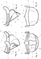
- Fig.1a-d show different views of a first embodiment of the implant according to the invention, in which the implant is denoted by arrow 1.
- Fig.1a shows a perspective view
- Fig.1b shows a side view
- Fig.1c shows a rear view
- Fig.1d shows a front view of the implant 1.
- the implant 1 comprises a lower frame section 2 and an upper frame section 3.
- the upper frame section 3 frames and supports a flexible structure 8 configured to rest against the wall of the atrium along the posterior annulus section, and comprises two end sections 9,10, which are located at opposite end regions of the upper frame section 3, and are configured to rest against the wall of the atrium above the anterior annulus section.
- the end sections 9,10 of the upper frame section 3 are protruding from the bend 5 in a circumferential direction of the annulus and are curved away from the bend 5.
- Fig.2a shows a side view of the implant 1 of Fig.1
- Fig.2b shows a detailed view of the first flexible sheet 11 and the second flexible sheet 12 of the upper frame section 3 of the implant 1 according to the first embodiment as depicted in Fig.1 .
- the first flexible sheet 11 and the second flexible sheet 12 define a gap 13 between them for allowing blood 14 to enter into a tubular cavity 15.
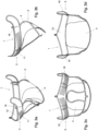
- Fig.3a-d show a second embodiment of the implant 1 according to the invention, which is equipped with a plurality of first fixing means 16 on its upper frame section 3, which are arranged and configured to engage with the wall of the atrium above the anterolateral and posteromedial commissure. Thereby the seating of the implant on the level of the annulus is secured.
- the first fixing means 16 are designed as fixing pins, which penetrate the heart tissue.
- Fig.3a shows a perspective view
- Fig.3b shows a side view
- Fig.3c shows a rear view
- Fig.3d shows a front view of the implant 1.
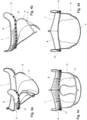
- Fig.4a-d show a third embodiment of the implant 1 according to the invention.
- Fig.4a shows a perspective view
- Fig.4b shows a side view
- Fig.4c shows a rear view
- Fig.4d shows a front view of the implant 1.
- the upper frame section 3 comprises a plurality of second fixing means 17, which are arranged in a row extending in a circumferential direction of the posterior annulus section of the implant 1, whereby the second fixing means 17 are arranged between the artificial leaflet 4 of the lower frame section 2 and the flexible structure 8 of the upper frame section 3 extending into the atrial region above the anterior leaflet.
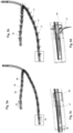
- Fig.5a-d show a detailed view of the second fixing means 17 as depicted in Fig.4 .
- Fig.5a shows a retracted position of the fixing means 17
- Fig.5b shows a deployed position of the fixing means 17
- Fig.5c shows a detail of Fig.5a
- Fig.5d shows a detail of Fig.5b .
- the second fixing means 17 are designed as retrievable hooks with a trident shape. The retrievable hooks are pushed out of an annulus tube 19 with a pusher in the direction of arrow 18 and deploy when exiting windows 20 of the annulus tube 19. This feature allows to retrieve the hooks in case of malpositioning.
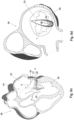
- Fig.6a shows that the implant 1 is advanced through a steerable catheter 24 into the left atrium 25 and is moved towards the left ventricle 26 until the orifice between the anterior leaflet 23 and the posterior leaflet 29 is reached.
- the clamping frame section 21 of the implant 1 is then gently released from the catheter 24 and precisely aligned at the center of the posterior prolapsed leaflet 29 from the ventricular side.
- the alignment takes place via activation of the clasp rocker 30, which is anchored via a connector hole 31 to the clamping frame section 21.
- the catheter 24 After aligning the clamping frame section 21 the catheter 24 is slowly slid up above the mitral leaflet plane, resulting in positioning the clamping frame section 21 between the prolapsed posterior leaflet 29 and the inner wall of the left ventricle 26.
- the upper frame section 3 of the implant 1 is actively swung towards the left atrial wall 27 by the aid of the atrial rocker 32, whereby the upper frame section 3 is positioned at the annular portion of the center of the posterior leaflet 29 ( Fig.6c ).
- Fig.6d shows a top view of the implantation status of Fig.6c according to arrow A.
- Fig.6e and Fig.6f show the final step of the implantation of the implant 1, in which the commissural pushers 33 are used to fully deploy the implant 1 and to precisely push the two end sections 9,10 of the upper frame section 3 into the commissures, i.e., the area in which the anterior leaflet 23 and the posterior leaflet 29 abut.
- Fig.6f shows a top view of the implantation status of Fig.6e according to arrow A.
- Fig.7a-b show a fourth embodiment of the implant 1 according to the invention.
- Fig.7a shows a side view
- Fig.7b shows a rear view.
- the clamping frame section 21 of the implant 1 is equipped with a fixing means 34 on its distal end.
- the fixing means 34 engages with a recess 35 in the center of the upper frame section 3 thereby connecting the clamping frame section 21 with the upper frame section 3.
- the fixing means 34 punctures the leaflet, which is arranged between the upper frame section 3 and the clamping frame section 21, and then engages with the recess 35. Thereby the implant 1 is fixed to the native leaflet and securely hold in place.
Landscapes
- Health & Medical Sciences (AREA)
- Cardiology (AREA)
- Oral & Maxillofacial Surgery (AREA)
- Transplantation (AREA)
- Engineering & Computer Science (AREA)
- Biomedical Technology (AREA)
- Heart & Thoracic Surgery (AREA)
- Vascular Medicine (AREA)
- Life Sciences & Earth Sciences (AREA)
- Animal Behavior & Ethology (AREA)
- General Health & Medical Sciences (AREA)
- Public Health (AREA)
- Veterinary Medicine (AREA)
- Prostheses (AREA)
Priority Applications (3)
| Application Number | Priority Date | Filing Date | Title |
|---|---|---|---|
| EP23020037.0A EP4403136A1 (de) | 2023-01-23 | 2023-01-23 | Implantat zur verbesserung der coaptation einer atrioventrikulären klappe |
| PCT/IB2024/050618 WO2024157165A1 (en) | 2023-01-23 | 2024-01-23 | Implant for improving coaptation of an atrioventricular valve |
| EP24701520.9A EP4654923A1 (de) | 2023-01-23 | 2024-01-23 | Implantat zur verbesserung der coaptation einer atrioventrikulären klappe |
Applications Claiming Priority (1)
| Application Number | Priority Date | Filing Date | Title |
|---|---|---|---|
| EP23020037.0A EP4403136A1 (de) | 2023-01-23 | 2023-01-23 | Implantat zur verbesserung der coaptation einer atrioventrikulären klappe |
Publications (1)
| Publication Number | Publication Date |
|---|---|
| EP4403136A1 true EP4403136A1 (de) | 2024-07-24 |
Family
ID=85036380
Family Applications (2)
| Application Number | Title | Priority Date | Filing Date |
|---|---|---|---|
| EP23020037.0A Withdrawn EP4403136A1 (de) | 2023-01-23 | 2023-01-23 | Implantat zur verbesserung der coaptation einer atrioventrikulären klappe |
| EP24701520.9A Pending EP4654923A1 (de) | 2023-01-23 | 2024-01-23 | Implantat zur verbesserung der coaptation einer atrioventrikulären klappe |
Family Applications After (1)
| Application Number | Title | Priority Date | Filing Date |
|---|---|---|---|
| EP24701520.9A Pending EP4654923A1 (de) | 2023-01-23 | 2024-01-23 | Implantat zur verbesserung der coaptation einer atrioventrikulären klappe |
Country Status (2)
| Country | Link |
|---|---|
| EP (2) | EP4403136A1 (de) |
| WO (1) | WO2024157165A1 (de) |
Cited By (1)
| Publication number | Priority date | Publication date | Assignee | Title |
|---|---|---|---|---|
| EP4649919A1 (de) * | 2024-05-13 | 2025-11-19 | AVVie GmbH | Implantat zur verbesserung der coaptation einer atrioventrikulären klappe in einem menschlichen herz |
Citations (3)
| Publication number | Priority date | Publication date | Assignee | Title |
|---|---|---|---|---|
| US20190060072A1 (en) * | 2017-08-28 | 2019-02-28 | Edwards Lifesciences Corporation | Transcatheter device for treating mitral regurgitation |
| WO2022006375A1 (en) * | 2020-07-01 | 2022-01-06 | Invalve Therapeutics, Inc. | Heart valve prostheses and related methods |
| US20220160499A1 (en) * | 2020-11-20 | 2022-05-26 | Half Moon Medical, Inc. | Tricuspid valve repair devices and associated systems and methods |
-
2023
- 2023-01-23 EP EP23020037.0A patent/EP4403136A1/de not_active Withdrawn
-
2024
- 2024-01-23 WO PCT/IB2024/050618 patent/WO2024157165A1/en not_active Ceased
- 2024-01-23 EP EP24701520.9A patent/EP4654923A1/de active Pending
Patent Citations (3)
| Publication number | Priority date | Publication date | Assignee | Title |
|---|---|---|---|---|
| US20190060072A1 (en) * | 2017-08-28 | 2019-02-28 | Edwards Lifesciences Corporation | Transcatheter device for treating mitral regurgitation |
| WO2022006375A1 (en) * | 2020-07-01 | 2022-01-06 | Invalve Therapeutics, Inc. | Heart valve prostheses and related methods |
| US20220160499A1 (en) * | 2020-11-20 | 2022-05-26 | Half Moon Medical, Inc. | Tricuspid valve repair devices and associated systems and methods |
Cited By (2)
| Publication number | Priority date | Publication date | Assignee | Title |
|---|---|---|---|---|
| EP4649919A1 (de) * | 2024-05-13 | 2025-11-19 | AVVie GmbH | Implantat zur verbesserung der coaptation einer atrioventrikulären klappe in einem menschlichen herz |
| WO2025237961A1 (en) * | 2024-05-13 | 2025-11-20 | Avvie Gmbh | Implant for improving coaptation of an atrioventricular valve in a human heart |
Also Published As
| Publication number | Publication date |
|---|---|
| WO2024157165A1 (en) | 2024-08-02 |
| EP4654923A1 (de) | 2025-12-03 |
Similar Documents
| Publication | Publication Date | Title |
|---|---|---|
| US12303387B2 (en) | Implant for improving coaptation of an atrioventricular valve | |
| US20240033081A1 (en) | Assemblies of an expandable prosthetic heart valve within an annuloplasty ring | |
| CN110520077B (zh) | 用于改善房室瓣的接合的植入物和方法 | |
| EP3846740B1 (de) | Implantat zur verbesserung der co-aptation einer atrioventrikulären klappe | |
| US11083572B2 (en) | Prosthetic leaflet device | |
| CN108652790B (zh) | 瓣膜假体和递送方法 | |
| EP3903737B1 (de) | Mitralklappenersatz mit atrialer verankerung | |
| EP2344074B1 (de) | Herzklappenprothese für die aufnahme einer perkutanen herzklappenprothesenimplantation | |
| US20150100116A1 (en) | Implant and method for improving coaptation of an atrioventricular valve | |
| JP2019500994A (ja) | 房室弁の接合を改善するインプラントおよび方法 | |
| EP4403136A1 (de) | Implantat zur verbesserung der coaptation einer atrioventrikulären klappe | |
| US20240390135A1 (en) | Single Frame Tethered Transcatheter Heart Valve | |
| HK40106677A (en) | Mitral valve replacement with atrial anchoring |
Legal Events
| Date | Code | Title | Description |
|---|---|---|---|
| PUAI | Public reference made under article 153(3) epc to a published international application that has entered the european phase |
Free format text: ORIGINAL CODE: 0009012 |
|
| STAA | Information on the status of an ep patent application or granted ep patent |
Free format text: STATUS: THE APPLICATION HAS BEEN PUBLISHED |
|
| AK | Designated contracting states |
Kind code of ref document: A1 Designated state(s): AL AT BE BG CH CY CZ DE DK EE ES FI FR GB GR HR HU IE IS IT LI LT LU LV MC ME MK MT NL NO PL PT RO RS SE SI SK SM TR |
|
| STAA | Information on the status of an ep patent application or granted ep patent |
Free format text: STATUS: THE APPLICATION IS DEEMED TO BE WITHDRAWN |
|
| 18D | Application deemed to be withdrawn |
Effective date: 20250125 |