EP3747377B1 - Chirurgisches instrument zur minimalinvasiven chirurgie - Google Patents
Chirurgisches instrument zur minimalinvasiven chirurgie Download PDFInfo
- Publication number
- EP3747377B1 EP3747377B1 EP20176985.8A EP20176985A EP3747377B1 EP 3747377 B1 EP3747377 B1 EP 3747377B1 EP 20176985 A EP20176985 A EP 20176985A EP 3747377 B1 EP3747377 B1 EP 3747377B1
- Authority
- EP
- European Patent Office
- Prior art keywords
- spring
- instrument
- coil spring
- shaft
- coil
- Prior art date
- Legal status (The legal status is an assumption and is not a legal conclusion. Google has not performed a legal analysis and makes no representation as to the accuracy of the status listed.)
- Active
Links
- 238000002324 minimally invasive surgery Methods 0.000 title claims description 9
- 239000012636 effector Substances 0.000 claims description 23
- 230000008878 coupling Effects 0.000 claims description 17
- 238000010168 coupling process Methods 0.000 claims description 17
- 238000005859 coupling reaction Methods 0.000 claims description 17
- 238000005452 bending Methods 0.000 claims description 16
- 239000000463 material Substances 0.000 claims description 13
- 230000033001 locomotion Effects 0.000 claims description 9
- 230000007423 decrease Effects 0.000 claims description 4
- 239000011295 pitch Substances 0.000 claims 1
- 238000004804 winding Methods 0.000 description 11
- 238000010586 diagram Methods 0.000 description 6
- 238000001356 surgical procedure Methods 0.000 description 5
- 230000007704 transition Effects 0.000 description 3
- 230000005540 biological transmission Effects 0.000 description 2
- 230000008859 change Effects 0.000 description 2
- 238000010276 construction Methods 0.000 description 2
- 238000004519 manufacturing process Methods 0.000 description 2
- 230000007246 mechanism Effects 0.000 description 2
- 238000010146 3D printing Methods 0.000 description 1
- 229910000639 Spring steel Inorganic materials 0.000 description 1
- 230000006978 adaptation Effects 0.000 description 1
- 238000004026 adhesive bonding Methods 0.000 description 1
- 239000004020 conductor Substances 0.000 description 1
- 238000005520 cutting process Methods 0.000 description 1
- 230000003247 decreasing effect Effects 0.000 description 1
- 230000001419 dependent effect Effects 0.000 description 1
- 238000011161 development Methods 0.000 description 1
- 230000018109 developmental process Effects 0.000 description 1
- 230000000694 effects Effects 0.000 description 1
- 230000005489 elastic deformation Effects 0.000 description 1
- 210000003746 feather Anatomy 0.000 description 1
- 238000009434 installation Methods 0.000 description 1
- 238000002357 laparoscopic surgery Methods 0.000 description 1
- 238000003698 laser cutting Methods 0.000 description 1
- 238000003754 machining Methods 0.000 description 1
- 238000003801 milling Methods 0.000 description 1
- 238000003825 pressing Methods 0.000 description 1
- 238000003672 processing method Methods 0.000 description 1
- 239000000523 sample Substances 0.000 description 1
- 238000003466 welding Methods 0.000 description 1
Images


Classifications
-
- A—HUMAN NECESSITIES
- A61—MEDICAL OR VETERINARY SCIENCE; HYGIENE
- A61B—DIAGNOSIS; SURGERY; IDENTIFICATION
- A61B17/00—Surgical instruments, devices or methods, e.g. tourniquets
- A61B17/28—Surgical forceps
- A61B17/29—Forceps for use in minimally invasive surgery
-
- A—HUMAN NECESSITIES
- A61—MEDICAL OR VETERINARY SCIENCE; HYGIENE
- A61B—DIAGNOSIS; SURGERY; IDENTIFICATION
- A61B17/00—Surgical instruments, devices or methods, e.g. tourniquets
- A61B17/00234—Surgical instruments, devices or methods, e.g. tourniquets for minimally invasive surgery
-
- A—HUMAN NECESSITIES
- A61—MEDICAL OR VETERINARY SCIENCE; HYGIENE
- A61B—DIAGNOSIS; SURGERY; IDENTIFICATION
- A61B18/00—Surgical instruments, devices or methods for transferring non-mechanical forms of energy to or from the body
-
- A—HUMAN NECESSITIES
- A61—MEDICAL OR VETERINARY SCIENCE; HYGIENE
- A61B—DIAGNOSIS; SURGERY; IDENTIFICATION
- A61B18/00—Surgical instruments, devices or methods for transferring non-mechanical forms of energy to or from the body
- A61B18/04—Surgical instruments, devices or methods for transferring non-mechanical forms of energy to or from the body by heating
- A61B18/12—Surgical instruments, devices or methods for transferring non-mechanical forms of energy to or from the body by heating by passing a current through the tissue to be heated, e.g. high-frequency current
- A61B18/14—Probes or electrodes therefor
- A61B18/1442—Probes having pivoting end effectors, e.g. forceps
- A61B18/1445—Probes having pivoting end effectors, e.g. forceps at the distal end of a shaft, e.g. forceps or scissors at the end of a rigid rod
-
- A—HUMAN NECESSITIES
- A61—MEDICAL OR VETERINARY SCIENCE; HYGIENE
- A61B—DIAGNOSIS; SURGERY; IDENTIFICATION
- A61B17/00—Surgical instruments, devices or methods, e.g. tourniquets
- A61B17/00234—Surgical instruments, devices or methods, e.g. tourniquets for minimally invasive surgery
- A61B2017/00292—Surgical instruments, devices or methods, e.g. tourniquets for minimally invasive surgery mounted on or guided by flexible, e.g. catheter-like, means
- A61B2017/003—Steerable
- A61B2017/00305—Constructional details of the flexible means
- A61B2017/00309—Cut-outs or slits
-
- A—HUMAN NECESSITIES
- A61—MEDICAL OR VETERINARY SCIENCE; HYGIENE
- A61B—DIAGNOSIS; SURGERY; IDENTIFICATION
- A61B17/00—Surgical instruments, devices or methods, e.g. tourniquets
- A61B2017/00681—Aspects not otherwise provided for
- A61B2017/00738—Aspects not otherwise provided for part of the tool being offset with respect to a main axis, e.g. for better view for the surgeon
-
- A—HUMAN NECESSITIES
- A61—MEDICAL OR VETERINARY SCIENCE; HYGIENE
- A61B—DIAGNOSIS; SURGERY; IDENTIFICATION
- A61B17/00—Surgical instruments, devices or methods, e.g. tourniquets
- A61B2017/00831—Material properties
- A61B2017/00862—Material properties elastic or resilient
-
- A—HUMAN NECESSITIES
- A61—MEDICAL OR VETERINARY SCIENCE; HYGIENE
- A61B—DIAGNOSIS; SURGERY; IDENTIFICATION
- A61B17/00—Surgical instruments, devices or methods, e.g. tourniquets
- A61B17/28—Surgical forceps
- A61B17/29—Forceps for use in minimally invasive surgery
- A61B2017/2901—Details of shaft
- A61B2017/2902—Details of shaft characterized by features of the actuating rod
-
- A—HUMAN NECESSITIES
- A61—MEDICAL OR VETERINARY SCIENCE; HYGIENE
- A61B—DIAGNOSIS; SURGERY; IDENTIFICATION
- A61B17/00—Surgical instruments, devices or methods, e.g. tourniquets
- A61B17/28—Surgical forceps
- A61B17/29—Forceps for use in minimally invasive surgery
- A61B2017/2926—Details of heads or jaws
- A61B2017/2927—Details of heads or jaws the angular position of the head being adjustable with respect to the shaft
- A61B2017/2929—Details of heads or jaws the angular position of the head being adjustable with respect to the shaft with a head rotatable about the longitudinal axis of the shaft
-
- A—HUMAN NECESSITIES
- A61—MEDICAL OR VETERINARY SCIENCE; HYGIENE
- A61B—DIAGNOSIS; SURGERY; IDENTIFICATION
- A61B17/00—Surgical instruments, devices or methods, e.g. tourniquets
- A61B17/28—Surgical forceps
- A61B17/29—Forceps for use in minimally invasive surgery
- A61B2017/2926—Details of heads or jaws
- A61B2017/2932—Transmission of forces to jaw members
- A61B2017/2939—Details of linkages or pivot points
-
- A—HUMAN NECESSITIES
- A61—MEDICAL OR VETERINARY SCIENCE; HYGIENE
- A61B—DIAGNOSIS; SURGERY; IDENTIFICATION
- A61B18/00—Surgical instruments, devices or methods for transferring non-mechanical forms of energy to or from the body
- A61B2018/00982—Surgical instruments, devices or methods for transferring non-mechanical forms of energy to or from the body combined with or comprising means for visual or photographic inspections inside the body, e.g. endoscopes
-
- A—HUMAN NECESSITIES
- A61—MEDICAL OR VETERINARY SCIENCE; HYGIENE
- A61B—DIAGNOSIS; SURGERY; IDENTIFICATION
- A61B34/00—Computer-aided surgery; Manipulators or robots specially adapted for use in surgery
- A61B34/30—Surgical robots
- A61B2034/302—Surgical robots specifically adapted for manipulations within body cavities, e.g. within abdominal or thoracic cavities
-
- A—HUMAN NECESSITIES
- A61—MEDICAL OR VETERINARY SCIENCE; HYGIENE
- A61B—DIAGNOSIS; SURGERY; IDENTIFICATION
- A61B34/00—Computer-aided surgery; Manipulators or robots specially adapted for use in surgery
- A61B34/30—Surgical robots
Definitions
- the invention relates to a surgical instrument for minimally invasive surgery, which has an instrument shaft with a distal end and a proximal end.
- a signal generator can be connected to the proximal end.
- the surgical instrument has an instrument head that is pivotally connected to the distal end of the instrument shaft via a hinge.
- the surgical instrument has an end effector which is mounted in the instrument head so that it can rotate about its longitudinal axis.
- the surgical instrument comprises at least one mechanical coupling element, which is arranged at least partially in the instrument shaft and is designed for transmitting and/or translating mechanical actuation signals from the signal generator for pivoting and rotating the instrument head.
- a coil spring bridges the hinge and connects the end effector to the coupler to rotate the end effector.
- a device for robot-assisted surgery in which a surgical instrument is guided with the aid of a manipulator arm of a manipulator and actuated by a signal generator of the manipulator arm.
- a coupling unit with drive elements and transmission means is arranged at the distal end of the manipulator arm, with which an instrument unit arranged at the distal end of an instrument shaft of the surgical instrument can be coupled via a sterile lock.
- the helical spring for bridging the hinge and for connecting the end effector to the coupling element for rotating the end effector is designed and arranged in such a way that the pitch of the spiral spring is set such that, with maximum bending of the spiral spring, spring turns correspond to a maximum pivoting position of the instrument head with respect to the bending direction of the inner spring side just come into contact or are still spaced apart.
- this has the disadvantage that internal wires, in particular actuating wires or electrical conductors, for example for high-frequency surgery, are not guided securely if the coils of the spring do not touch or only touch in the maximum angled state.
- the spring is angled relatively sharply essentially at a single point in a plane orthogonal to the longitudinal axis of the instrument shaft, in which the axis of rotation of the hinge also runs, and the coils in are highly stressed in this area, whereas the adjoining further areas are not bent or are bent to a much lesser extent.
- the bending properties of the spring can be individually adapted when the distal end of the spring is pivoted laterally away from the longitudinal axis of the instrument shaft.
- the shape of the helical spring can be adjusted after pivoting the distal end of the helical spring away from the longitudinal axis of the instrument shaft, preferably to the effect that a main angling occurs centrally, ie in the region of the axis of rotation of the joint.
- the coils in the area of the main bend are less stressed than in the case of helical springs according to the prior art, due to a preferably low spring constant.
- the helical spring can also be configured in such a way that a region in which the main deflection of the spring occurs is at a distance from the axis of rotation of the at least one joint in the proximal direction or in the distal direction. It is particularly advantageous if at least two, in particular three or four, main bending points are formed as a result of the spring constants when the instrument head is angled. Such a construction is particularly advantageous for a joint which is composed of a large number of hinges.
- the joint can also be used as a flexure joint, as is evident from the document WO 2006/113216 A2 , known as a single hinge, as is clear from the document EP 2 377 477 A1 is known, and / or as a hinged chain, as is known from the document EP 2 777 561 B1 is known to be trained.
- At least one actuating wire and/or electrically conductive wire is fed through inside the helical spring, this can be safely guided through the easily adaptable bending shape of the helical spring even when the instrument head is pivoted and the associated lateral deflection or bending of the helical spring, so that damage to the latter is avoided wires are avoided.
- the spring constant decreases from the distal end of the helical spring and from the proximal end of the helical spring, preferably continuously, in particular uniformly, towards the center or towards a central area with a constant spring constant of the helical spring or continuously, in particular uniformly, towards this area. increases. In this way, a main deflection can be achieved in the middle of the spring.
- the winding of the helical spring has a rectangular cross section.
- high spring constants can be achieved in a small installation space.
- a rotational movement is transmitted via the helical spring around the longitudinal axis of the helical spring, there is only a slight elastic deformation of the spring, so that the end effector can be operated easily.
- such a helical spring can be easily manufactured using mechanical processing methods such as milling and winding, or alternatively using a 3D printer.
- the winding of the helical spring has a different cross-sectional area in the areas with different spring constants.
- the spring constant can also be different in regions of the helical spring be when the entire coil spring is made of the same material.
- the spring constant can also be combined in connection with other measures for forming different spring constants in the areas of the helical spring.
- the winding of the helical spring has a different gradient in the areas with different spring constants. This enables a simple production of a helical spring with areas of different spring constants.
- the winding of the helical spring has sections with materials with different moduli of elasticity.
- the spring constant can be generated differently in the areas simply by the fact that the areas of the helical spring are made of different materials. This is easily possible in particular when a plurality of spring segments are combined to form an overall helical spring in that the turns of the regions are welded or glued to one another or connected in some other way.
- the different materials can also be used one after the other in a 3D print to produce the spring. A continuous transition between different materials or material configurations is also conceivable.
- the helical spring is a linear spring.
- the helical spring is preferably designed in such a way that when force is applied in the direction of the central axis of the helical spring, the spring deforms uniformly with increasing force, ie linearly with respect to the force. In this case, however, a different deformation takes place in each of the areas with different spring constants.
- the coupling element comprises a rotary shaft, when the proximal end of the helical spring is connected to the rotary shaft in a rotationally fixed manner and when the rotary shaft is rotatably mounted in the instrument shaft.
- This allows for a simple and compact arrangement of the components of the coupling element inside the instrument shaft, with the rotating tube shaft offering a safe, low-torsion drive option in the direction of rotation for rotating the instrument head or the end effector.
- the helical spring is arranged in a prestressed manner between the rotating tube shaft and the instrument head.
- the torsional properties of the helical spring can be further adjusted.
- the helical spring is designed and arranged in such a way that when the instrument head is pivoted, the coils of the helical spring come into contact with the inner side of the helical spring with respect to the bending direction from a predetermined pivoting position and that the coils of the helical spring when the instrument head is pivoted over beyond the predetermined pivoting position up to a maximum pivoting position of the instrument head on the inner spring side with respect to the bending direction with a pressing force.
- the coils of the helical spring can have a greater spacing on the outer spring side in the maximum pivoting position of the instrument head than in their initial position with a straight instrument head, ie when the instrument head is not pivoted about the axis of rotation of the joint. Due to the increased distance on the outer side of the spring, the windings are pulled apart there, at least in the maximum pivoting position. This ensures that the windings on the inside always lie against one another and inside the helical spring from touching in the predetermined pivoting position up to the maximum pivoting position guided wires or trains are guided safely and with little friction on the inside of the spring, so that damage to these wires is avoided.
- the instrument head can be pivoted by a predetermined angle about an axis of rotation with the aid of the coupling element, the axis of rotation being orthogonal to the longitudinal axis of the instrument shaft.
- the joint can be designed as a simple hinge. It is particularly advantageous if the instrument head is pivoted by a translational movement of an inner shaft arranged between the instrument shaft and the rotating tube shaft along its longitudinal axis. In this way, a simple and secure coupling of the coupling element to the instrument head is possible, in order to enable both a pivoting of the entire instrument head and a rotational movement of the end effector and/or the instrument head.
- the axis of rotation of the joint runs through and orthogonally to the longitudinal axis of the helical spring. This enables a simple and compact construction of the instrument in the area of the instrument head and the transition between the instrument shaft and the instrument head.
- the helical spring is not or only slightly deformed in the direction of rotation of the helical spring for rotating the instrument head or the end effector with the forces normally required for rotating the instrument head.
- simple and safe actuation of the surgical instrument is possible.
- safe handling of the surgical instrument is ensured since a desired rotational movement that is initiated is transmitted relatively exactly via the helical spring.
- the signal transmitter connected to the proximal end of the instrument shaft is a manual operating unit and/or a coupling element for coupling the surgical element to at least one drive unit of a manipulator arm of a manipulator. This allows the surgical instrument to be operated easily and safely.
- the surgical instrument preferably comprises at least one end effector arranged on the instrument head that can be inserted into a body opening of a patient, such as a clamp, scissors, a gripper, a needle holder, a microdissector, a clamping device, a stapling device, a rinsing and/or suction device, a cutting blade , a cautery probe, a catheter and/or a suction nozzle or an end effector for high-frequency surgery.
- the surgical instrument can optionally have different end effectors that can be used for common minimally invasive interventions, in particular in laparoscopic surgery. However, other surgical instruments can also be used additionally or alternatively.
- FIG 1 shows a surgical instrument 10 for minimally invasive surgery.
- This instrument 10 has an instrument shaft 12 with a distal end 14 and a proximal end 16.
- the proximal end 16 of the instrument shaft 12 is connected to an instrument unit 18.
- the surgical instrument 10 can be connected to a coupling unit of a manipulator arm of a manipulator.
- manipulators are also referred to as telemanipulator systems and are used for robot-assisted surgery.
- Such manipulators are in particular in the documents EP 3 025 667 A1 and WO 2016/083189 A1 disclosed.
- the solution according to the invention can also be used for laparoscopic hand instruments without any changes.
- the surgical instrument 10 has an instrument head 20 connected to the distal end 14 of the instrument shaft 12 via a joint designed as a hinge 22.
- the instrument head 20 comprises an end effector 24 which is mounted on the instrument head 20 so that it can rotate about its longitudinal axis.
- FIG. 12 shows a sectional view of a distal portion of the surgical instrument 10.
- FIG figure 1 Inside the instrument shaft 12 is a rotary tube shaft 26, which is mounted such that it can rotate with respect to the instrument shaft 12, and an inner shaft 28 arranged between the rotary tube shaft 26 and the instrument shaft 12, wherein the inner shaft 28 can be moved at least in the longitudinal direction of the instrument shaft 12 in order to tilt the instrument head 20 by one in figure 2 pivot axis 30 of rotation, which is additionally drawn in orthogonally to the plane of the drawing, in the direction of arrow P1.
- the arrow P1 thus indicates the pivoting direction of the instrument head 20, in which it is from the figure 2 rest position shown can be moved out.
- the maximum angle through which the instrument head 20 can be pivoted in the direction of the arrow P1 is generally in a range between 60° and 90°, preferably 65° or 70°. In other embodiments, instead of the hinge 22, other joints can also be used.
- the instrument head 20 is about the longitudinal axis of the instrument shaft via a ball bearing 32 12 in the in figure 2 rest position shown rotatable. So that the instrument head 20 can also be rotated when the instrument head 20 is pivoted about the axis of rotation 30, a coil spring 34 is provided between the rotary tube shaft 26 and the instrument head 20 to transmit the rotary movement, the proximal end of which is non-rotatably connected to the rotary tube shaft 26 and the distal end is non-rotatably connected to the proximal end of the instrument head 20 .
- the coil spring 34 is arranged inside the hinge 22 and bridges this.
- the end effector 24 has a first jaw part 36 and a second jaw part 38.
- the first jaw part 36 is rigidly connected to the instrument head 20.
- the second jaw part is pivotable about the pivot axis defined by the pin 40 so that the gripper formed by the first jaw part 36 and the second jaw part 38 can be opened and closed by pivoting the second jaw part 38 about the pin 40 .
- Pivoting of the second jaw part 38 about the axis of rotation formed by the pin 40 is controlled by an actuating wire 42 and an actuating mechanism 48, with the actuating wire 42 performing a pushing movement in the direction of the distal end to open the gripper and being pulled towards the proximal end to close the gripper becomes.
- the actuating wire 42 runs inside the helical spring 34 through the latter, so that an actuation of the end effector 24 or an actuation of the gripper is possible even when the instrument head 20 is pivoted.
- the second jaw part 38 is also designed to be movable.
- an electrical connection to the end effector 24 can also be established via the actuating wire 42 in order to use the end effector 24 and the surgical instrument 10 for high-frequency surgery.
- the inner shaft 28 is connected to the proximal end of a pull lever 44 .
- the pull lever 44 is articulated on the instrument head 20 such that it can be pivoted about a pivot axis 46 .
- a movement of the proximal end of the pull lever 44 in the direction of the proximal end of the instrument shaft 12 initiated by the inner shaft 28 pivots the instrument head about the axis of rotation 30 of the hinge 22 and the coil spring 34 is bent laterally.
- figure 3 shows the spring 24 figure 2 in a pre-stressed state with which the coil spring 34 is arranged in the surgical instrument 10 .
- the coil spring 34 is made of a spring steel, with the cross-sectional area of the coils decreasing from the proximal end of the coil spring 34 and from the distal end of the coil spring 34 towards the center of the coil spring 34, so that the spring constant from the proximal end and from the distal end of the coil spring 34 respectively decreases.
- the gradient of the coil spring 34 in the relaxed state and/or in the prestressed state is preferably constant.
- the pitch of the coils may be different, or the spring properties of the material may be different in portions of the coils. This can be done in particular by assembling the helical spring 34 from different coil sections. Alternatively or additionally, individual winding sections can be partially hardened.
- figure 4 shows the feather figure 3 in a state after the instrument head 20 has been pivoted relative to the instrument shaft 28 by an angle of approximately 45°, with a longitudinal axis of the instrument head and the longitudinal axis of the instrument shaft spanning an angle of 135°.
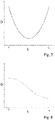
- Figure 12 shows the curve of the spring constant D over the length L of a helical spring, where zero is the proximal end of the helical spring and L0 is the distal end of the helical spring.
- a helical spring with a constant spring constant D is a helical spring with a constant spring constant D, as used in surgical instruments in the prior art.
- figure 6 shows the progression of the spring constant D over the length of the helical spring 34 according to a first embodiment.
- the spring constant D increases continuously from the proximal end of the coil spring 34 to the distal end of the coil spring 34 . This can be done, for example, by the fact that the cross section of the windings also increases continuously from the proximal end to the distal end of the helical spring 34 .
- figure 7 shows a curve of the spring constant D over the length L of the coil spring 34 according to a second embodiment.
- the course of the spring constant D shown is the course of the change in cross section of the helical spring 34 according to FIGS Figures 2 to 4 caused spring constant D when the helical spring 34 has a constant pitch or constant pitch and over the entire length of the helical spring 34 has constant material properties.
- figure 8 shows the course of the spring constant D over the length of a helical spring 34 according to a third embodiment.
- the spring constant does not decrease linearly from the proximal end to the distal end.
- figure 9 shows the course of the spring constant D over the length L of the helical spring 34 according to a fourth embodiment.
- the coil spring 34 has a first region 50 with a constant spring constant D1 and a second region 52 with a constant spring constant D2.
- Such a progression of the spring constant D is achieved, for example, by a stepped cross-sectional change in the winding of the coil spring 34 and/or by using different materials in the two areas 50, 52 with a constant spring constant D1, D2, with the two areas 50, 52 being made of different materials in the Middle of the coil spring 34, ie are connected to each other at the stepped transition between low spring constant D1 and high spring constant D2.
- figure 10 shows the course of the spring constant D over the length of a helical spring 34 according to a fifth embodiment.
- the spring constant D of the coil spring 34 is high at the distal end 54 and proximal end 56 and in the center 58, with a minimum between the distal end 54 and the center 58 and between the center 58 and the proximal end 56 60, 62 of the spring constant D is reached.
- the inside figure 10 The course shown has the consequence that in the areas 60, 62 with a minimum spring constant D there is a large bending when pivoting the instrument head 20 and in the areas 54, 56, 58 with a high spring constant there is less deformation.
- an individual adaptation of the torsion or bending properties of the helical spring 34 when pivoting the instrument head 20 can be achieved through the areas with different spring constants.
- the spring constant D can be changed over the length of the coil spring 34 in such a way that the main bending area occurs in the middle, ie in the area of the axis of rotation 30 of the hinge 22, not in the middle, ie in front of and/or after the axis of rotation 30 of the hinge 22, with one two, three or four bending points can be provided.
- Coil springs 34 with areas with different spring constants D can be produced in particular by winding, machining, laser cutting, 3D printing, welding, gluing and other suitable production methods.
- the variation of the spring constant D over the length L of the helical spring 34 takes place in particular by changing the cross section of the coil, by a different pitch of the coil of the helical spring 34, by different materials and/or material gradients, by partial hardening or other suitable choice of the spring configuration.
- the torsional rigidity of the helical spring 34 and the behavior of the helical spring 34 when the instrument head 20 is angled can be influenced by suitable variation of the spring constant D over the length of the helical spring 34 .
Description
- Die Erfindung betrifft ein chirurgisches Instrument zur minimalinvasiven Chirurgie, das einen Instrumentenschaft mit einem distalen Ende und einem proximalen Ende hat. Mit dem proximalen Ende ist ein Signalgeber verbindbar. Das chirurgische Instrument hat einen Instrumentenkopf, der über ein Scharnier schwenkbar mit dem distalen Ende des Instrumentenschafts verbunden ist. Ferner hat das chirurgische Instrument einen Endeffektor, der im Instrumentenkopf um seine Längsachse drehbar gelagert ist. Weiterhin umfasst das chirurgische Instrument mindestens ein mechanisches Kopplungselement, das zumindest teilweise im Instrumentenschaft angeordnet und zum Übertragen und/oder Übersetzen mechanischer Betätigungssignale des Signalgebers zum Schwenken und Drehen des Instrumentenkopfs ausgebildet ist. Eine Schraubenfeder überbrückt das Scharnier und verbindet den Endeffektor mit dem Kopplungselement, um den Endeffektor zu drehen. Ein solches Instrument zur minimalinvasiven Chirurgie ist beispielsweise aus dem Dokument
EP 2 377 477 A1 bekannt. - Aus dem Dokument
EP 3 025 667 A1 ist eine Vorrichtung zur robotergestützten Chirurgie bekannt, bei der ein chirurgisches Instrument mit Hilfe eines Manipulatorarms eines Manipulators geführt und über einen Signalgeber des Manipulatorarms betätigt wird. Hierzu ist am distalen Ende des Manipulatorarms eine Koppeleinheit mit Antriebselementen und Übertragungsmitteln angeordnet, mit der eine am distalen Ende eines Instrumentenschafts des chirurgischen Instruments angeordnete Instrumenteneinheit über eine Sterilschleuse koppelbar ist. - Bei dem aus dem Dokument
EP 2 377 477 A1 bekannten chirurgischen Instrument ist die Schraubenfeder zum Überbrücken des Scharniers und zum Verbinden des Endeffektors mit dem Kopplungselement zum Drehen des Endeffektors derart ausgebildet und angeordnet, dass die Ganghöhe der Spiralfeder so eingestellt ist, dass bei maximaler Biegung der Spiralfeder entsprechend einer maximalen Verschwenkungsposition des Instrumentenkopfs Federwindungen an der bezüglich der Biegerichtung inneren Federseite gerade in Anlage kommen oder noch voneinander beabstandet sind. Dies hat insbesondere den Nachteil, das innenliegende Drähte, insbesondere Betätigungsdrähte oder elektrische Leiter z.B. zur Hochfrequenzchirurgie nicht sicher geführt sind, wenn die Windungen der Feder sich nicht oder nur im maximal abgewinkelten Zustand berühren. - Darüber hinaus ist es bei dem aus dem Stand der Technik bekannten Instrumenten nachteilig, dass die Feder im Wesentlichen an einer einzigen Stelle in einer zur Längsachse des Instrumentenschachts orthogonalen Ebene, in der auch die Drehachse des Scharniers verläuft, relativ stark abgewinkelt wird und die Windungen in diesem Bereich hoch beansprucht werden, wohingegen die angrenzenden weiteren Bereiche nicht oder wesentlich geringer gebogen werden.
- Davon ausgehend ergibt sich die Aufgabe, ein chirurgisches Instrument zur minimalinvasiven Chirurgie anzugeben, das einfach aufgebaut ist und eine sichere Funktion gewährleistet.
- Diese Aufgabe wird durch ein chirurgisches Instrument zur minimalinvasiven Chirurgie mit den Merkmalen des Anspruchs 1 gelöst. Vorteilhafte Weiterbildungen sind in den abhängigen Ansprüchen angegeben.
- Durch ein chirurgisches Instrument zur minimalinvasiven Chirurgie mit den Merkmalen des Anspruchs 1 ist es möglich, das Biegeverhalten der Feder beim Abwinkein des Instrumentenkopfs zu beeinflussen. Insbesondere kann durch die Wahl geeigneter Federkonstanten in unterschiedlichen Bereichen der Schraubenfeder eine individuelle Anpassung der Biegeeigenschaften der Feder beim seitlichen Verschwenken des distalen Endes der Feder von der Längsachse des Instrumentenschafts weg erfolgen. Insbesondere kann die Form der Schraubenfeder nach dem Verschwenken des distalen Endes der Schraubenfeder von der Längsachse des Instrumentenschafts weg angepasst werden, vorzugsweise dahingehend, dass eine Hauptabwinklung mittig, d.h. im Bereich der Drehachse des Gelenks, erfolgt. Hierbei werden die Windungen im Bereich der Hauptabwinklung auf Grund einer vorzugsweise niedrigen Federkonstante weniger beansprucht als bei Schraubenfedern nach dem Stand der Technik. Mit Hilfe der unterschiedlichen Federkonstanten kann die Schraubenfeder aber auch derart konfiguriert werden, dass ein Bereich, indem die Hauptabwinklung der Feder erfolgt, einen Abstand zur Drehachse des mindestens einen Gelenks in proximaler Richtung oder in distaler Richtung hat. Besonders vorteilhaft ist es, wenn durch die Federkonstanten mindestens zwei, insbesondere drei oder vier, Hauptbiegestellen beim Abwinkeln des Instrumentenkopfs ausgebildet werden. Eine solche Konstruktion ist insbesondere für ein Gelenk, welches sich aus einer Vielzahl von Scharnieren zusammensetzt, vorteilhaft. Es ist auch möglich, mit Hilfe der unterschiedlichen Federkonstanten in Bereichen der Schraubenfeder einen gewünschten Biegeradius oder einen gewünschten Kurvenverlauf der Längsachse der Feder zu erzeugen. Hierdurch ist es möglich, dass eine Kraftübertragung zur Rotation des Instrumentenkopfs sicher und insbesondere kontinuierlich und ruckelfrei erfolgen kann. Jedoch kann das Gelenk auch als Festkörpergelenk, wie es aus dem Dokument
WO 2006/113216 A2 , bekannt ist, als einzelnes Scharnier, wie es aus dem DokumentEP 2 377 477 A1 bekannt ist, und/oder als Scharnierkette, wie sie aus dem DokumentEP 2 777 561 B1 bekannt ist, ausgebildet sein. - Wird im Inneren der Schraubenfeder mindestens ein Betätigungsdraht und/oder elektrisch leitender Draht hindurch geführt, können diese durch die einfach anpassbare Biegeform der Schraubenfeder auch beim Schwenken des Instrumentenkopf und dem damit verbundenen seitlichen Auslenken bzw. Verbiegen der Schraubenfeder sicher geführt werden, so dass Beschädigungen dieser Drähte vermieden werden.
- Besonders vorteilhaft ist es, wenn die Federkonstante vom distalen Ende der Schraubenfeder und vom proximalen Ende der Schraubenfeder, vorzugsweise kontinuierlich, insbesondere gleichmäßig, zur Mitte oder zu einem mittleren Bereich mit konstanter Federkonstante der Schraubenfeder hin abnimmt oder zu diesem Bereich hin kontinuierlich, insbesondere gleichmäßig, zunimmt. Hierdurch kann eine Hauptabwinkelung in der Mitte der Feder erreicht werden.
- Ferner ist es vorteilhaft, wenn die Windung der Schraubenfeder einen rechteckigen Querschnitt hat. Hierdurch können hohe Federkonstanten bei geringem Bauraum erreicht werden. Darüber hinaus erfolgt bei einer Übertragung einer Drehbewegung über die Schraubenfeder um die Längsachse der Schraubenfeder herum nur eine geringe elastische Verformung der Feder, so dass eine einfache Bedienbarkeit des Endeffektors möglich ist. Darüber hinaus lässt sich eine solche Schraubenfeder einfach durch mechanische Bearbeitungsverfahren, wie Fräsen und Wickeln, oder alternativ mit Hilfe eines 3D-Druckers herstellen.
- Ferner ist es vorteilhaft, wenn die Windung der Schraubenfeder in den Bereichen mit unterschiedlicher Federkonstante eine unterschiedliche Querschnittsfläche hat. Durch die Änderung der Querschnittsfläche in Betrag und/oder der Form kann die Federkonstante in Bereichen der Schraubenfeder auch dann unterschiedlich sein, wenn die gesamte Schraubenfeder aus demselben Material hergestellt ist. Darüber hinaus lässt sich die Federkonstante durch Änderung der Querschnittsfläche auch in Verbindung mit weiteren Maßnahmen zur Ausbildung unterschiedlicher Federkonstanten in den Bereichen der Schraubenfeder kombinieren.
- Ferner ist es vorteilhaft, wenn die Windung der Schraubenfeder in den Bereichen mit unterschiedlicher Federkonstante eine andere Steigung hat. Hierdurch ist eine einfache Herstellung einer Schraubenfeder mit Bereichen unterschiedlicher Federkonstanten möglich.
- Ferner ist es vorteilhaft, wenn die Windung der Schraubenfeder Abschnitte mit Materialien mit unterschiedlichen Elastizitätsmodulen aufweist. Hierdurch kann die Federkonstante in den Bereichen einfach dadurch unterschiedlich erzeugt werden, dass die Bereiche der Schraubenfeder aus unterschiedlichen Materialien hergestellt sind. Dies ist insbesondere dann einfach möglich, wenn mehrere Federsegmente zu einer Gesamtschraubenfeder zusammengesetzt werden, indem die Windung der Bereiche miteinander verschweißt oder verklebt oder anderweitig verbunden werden. Alternativ können die unterschiedlichen Materialien auch nacheinander bei einem 3D-Druck zur Herstellung der Feder verwendet werden. Dabei ist auch ein kontinuierlicher Übergang zwischen verschiedenen Materialien oder Materialkonfigurationen denkbar.
- Besonders vorteilhaft ist es, wenn die Schraubenfeder eine lineare Feder ist. Hierbei ist die Schraubenfeder vorzugsweise derart ausgebildet, dass sich die Feder bei Krafteinwirkung in Richtung der Mittelachse der Schraubenfeder mit zunehmender Kraft gleichmäßig, d.h. linear zur Kraft verformt. Hierbei erfolgt jedoch eine unterschiedliche Verformung in jedem der Bereiche mit unterschiedlicher Federkonstante.
- Ferner ist es vorteilhaft, wenn das Kopplungselement einen Drehrohrschaft umfasst, wenn das proximale Ende der Schraubenfeder mit dem Drehrohrschaft drehfest verbunden ist und wenn der Drehrohrschaft drehbar im Instrumentenschaft gelagert ist. Hierdurch ist eine einfache und kompakte Anordnung der Bestandteile des Kopplungselements im Inneren des Instrumentenschafts möglich, wobei der Drehrohrschaft eine sichere, in Drehrichtung torsionsarme Antriebsmöglichkeit zum Drehen des Instrumentenkopfs bzw. des Endeffektors bietet.
- Bei einer alternativen Ausführungsform ist die Schraubenfeder zwischen dem Drehrohrschaft und dem Instrumentenkopf vorgespannt angeordnet. Hierdurch können die Torsionseigenschaften der Schraubenfeder weiter angepasst werden. Ferner ist es vorteilhaft, wenn die Schraubenfeder derart ausgebildet und angeordnet ist, dass die Windungen der Schraubenfeder beim Verschwenken des Instrumentenkopfs ab einer vorbestimmten Schwenkposition an der bezüglich der Biegerichtung inneren Seite der Schraubenfeder in Anlage kommen und dass die Windungen der Schraubenfeder beim Verschwenken des Instrumentenkopfs über die vorbestimmte Schwenkposition hinaus bis zu einer maximalen Schwenkposition des Instrumentenkopfs an der bezüglich der Biegerichtung inneren Federseite mit einer Andruckkraft aufeinander drücken. Hierbei können die Windungen der Schraubenfeder in der maximalen Schwenkposition des Instrumentenkopfs an der äußeren Federseite einen größeren Abstand haben als in ihrer Ausgangslage mit geradem Instrumentenkopf, d.h. wenn der Instrumentenkopf nicht um die Drehachse des Gelenks verschwenkt ist. Durch den vergrößerten Abstand an der äußeren Federseite sind die Windungen dort zumindest in der maximalen Schwenkposition auseinander gezogen. Hierdurch wird sichergestellt, dass die Windungen an der Innenseite ab dem Berühren in der vorbestimmten Schwenkposition bis zur maximalen Schwenkposition immer aneinander liegen und im Inneren der Schraubenfeder geführten Drähte bzw. Züge an der Innenseite der Feder sicher und reibungsarm geführt sind, so dass Beschädigungen dieser Drähte vermieden werden.
- Ferner ist es vorteilhaft, wenn der Instrumentenkopf mit Hilfe des Kopplungselements um eine Drehachse um einen vorbestimmten Winkel schwenkbar ist, wobei die Drehachse orthogonal zur Längsachse des Instrumentenschafts ist. Hierdurch ist eine einfache Ausbildung und Anordnung des Gelenks möglich. Das Gelenk kann hierbei als einfaches Scharnier ausgebildet sein. Hierbei ist es besonders vorteilhaft, wenn das Schwenken des Instrumentenkopfs durch eine Translationsbewegung eines zwischen Instrumentenschaft und Drehrohrschaft angeordneten Innenschafts entlang dessen Längsachse erfolgt. Hierdurch ist eine einfache und sichere Kopplung des Kopplungselements mit dem Instrumentenkopf möglich, um sowohl ein Verschwenken des gesamten Instrumentenkopfs als auch einer Rotationsbewegung des Endeffektors und/oder des Instrumentenkopfs sicher zu ermöglichen.
- Besonders vorteilhaft ist es, wenn die Drehachse des Gelenks durch und orthogonal zur Längsachse der Schraubenfeder verläuft. Hierdurch ist ein einfacher und kompakter Aufbau des Instruments im Bereich des Instrumentenkopfs und des Übergangs zwischen Instrumentenschaft und Instrumentenkopf möglich.
- Besonders vorteilhaft ist es, wenn die Schraubenfeder in Drehrichtung der Schraubenfeder zum Drehen des Instrumentenkopfs bzw. des Endeffektors bei üblichen zur Drehung des Instrumentenkopfs erforderlichen Kräften nicht oder nur gering verformt. Hierdurch ist eine einfache und sichere Betätigung des chirurgischen Instruments möglich. Insbesondere ist eine sichere Handhabung des chirurgischen Instruments gewährleistet, da eine gewünschte initiierte Drehbewegung relativ exakt über die Schraubenfeder übertragen wird.
- Ferner ist es vorteilhaft, wenn der mit dem proximalen Ende des Instrumentenschafts verbundene Signalgeber eine manuelle Betätigungseinheit und/oder ein Koppelelement zum Koppeln des chirurgischen Elements mit mindestens einer Antriebseinheit eines Manipulatorarms eines Manipulators ist. Hierdurch kann eine einfache und sichere Bedienung des chirurgischen Instruments erfolgen.
- Das chirurgische Instrument umfasst vorzugsweise mindestens einen in eine Körperöffnung eines Patienten einführbaren an Instrumentenkopf angeordneten Endeffektor, wie eine Klemme, eine Schere, einen Greifer, einen Nadelhalter, einen Mikrodissektor, eine Klammervorrichtung, eine Heftvorrichtung, eine Spül- und/oder Absaugvorrichtung, eine Schneidklinge, eine Kauterisationssonde, einen Katheter und/oder eine Saugdüse oder ein Endeffektor zur Hochfrequenzchirurgie. Dadurch kann das chirurgische Instrument wahlweise unterschiedliche Endeffektoren haben, die für gängige minimal-invasive Eingriffe, insbesondere bei der laparoskopischen Chirurgie, eingesetzt werden können. Es können jedoch auch andere chirurgische Instrumente zusätzlich oder alternativ eingesetzt werden.
- Nachfolgend werden weitere Merkmale und Vorteile anhand von Ausführungsformen in Verbindung mit den beigefügten Figuren beschrieben.
- Es zeigt:
- Figur 1
- eine perspektivische Darstellung eines chirurgischen Instruments zur minimalinvasiven Chirurgie zum Einsatz mit einem Manipulator;
- Figur 2
- eine Schnittdarstellung eines distalen Abschnitts des Instruments nach
Figur 1 ; - Figur 3
- eine zum Übertragen einer Drehbewegung im Instrument nach den Figuren 1 und 2 eingesetzte Schraubenfeder;
- Figur 4
- die Schraubenfeder nach
Figur 3 in einem um 45° abgewinkelten Zustand; - Figur 5
- ein Diagramm mit dem Verlauf der Federkonstanten D über die Länge einer Schraubenfeder gemäß dem Stand der Technik;
- Figur 6
- ein Diagramm mit dem Verlauf der Federkonstanten D über die Länge L der Schraubenfeder gemäß einer ersten Ausführungsform:
- Figur 7
- ein Diagramm mit dem Verlauf der Federkonstanten D über die Länge L der Schraubenfeder gemäß einer zweiten Ausführungsform;
- Figur 8
- ein Diagramm mit dem Verlauf der Federkonstanten D über die Länge L der Schraubenfeder gemäß einer dritten Ausführungsform;
- Figur 9
- ein Diagramm mit dem Verlauf der Federkonstanten D über die Länge L der Schraubenfeder gemäß einer vierten Ausführungsform; und
- Figur 10
- ein Diagramm mit dem Verlauf der Federkonstanten D über die Länge L der Schraubenfeder gemäß einer fünften Ausführungsform.
-
Figur 1 zeigt ein chirurgisches Instrument 10 zur minimalinvasiven Chirurgie. Dieses Instrument 10 hat einen Instrumentenschaft 12 mit einem distalen Ende 14 und einem proximalen Ende 16. Das proximale Ende 16 des Instrumentenschafts 12 ist mit einer Instrumenteneinheit 18 verbunden. Über die Instrumenteneinheit 18 ist das chirurgische Instrument 10 mit einer Koppeleinheit eines Manipulatorarms eines Manipulators verbindbar. Solche Manipulatoren werden auch als Telemanipulatorsysteme bezeichnet und dienen zur robotergestützten Chirurgie. Solche Manipulatoren sind insbesondere in den DokumentenEP 3 025 667 A1 undWO 2016/083189 A1 offenbart. Die erfindungsgemäße Lösung kann ohne Änderungen auch für laparoskopische Handinstrumente verwendet werden. - Das chirurgische Instrument 10 hat einen mit dem distalen Ende 14 des Instrumentenschafts 12 über ein als Scharnier 22 ausgebildetes Gelenk verbundenen Instrumentenkopf 20. Der Instrumentenkopf 20 umfasst einen Endeffektor 24, der am Instrumentenkopf 20 um seine Längsachse drehbar gelagert ist.
-
Figur 2 zeigt eine Schnittdarstellung eines distalen Abschnitts des chirurgischen Instruments 10 nachFigur 1 . Im Inneren des Instrumentenschafts 12 ist ein drehbar zum Instrumentenschaft 12 gelagerter Drehrohrschaft 26 sowie ein zwischen dem Drehrohrschaft 26 und dem Instrumentenschaft 12 angeordneter Innenschaft 28 angeordnet, wobei der Innenschaft 28 zumindest in Längsrichtung des Instrumentenschafts 12 bewegt werden kann, um den Instrumentenkopf 20 um eine inFigur 2 zusätzlich eingezeichnete orthogonal zur Zeichnungsebene verlaufende Drehachse 30 in Richtung des Pfeils P1 zu verschwenken. Der Pfeil P1 gibt somit die Schwenkrichtung des Instrumentenkopfs 20 an, in die er aus der inFigur 2 gezeigten Ruhelage herausbewegt werden kann. Der maximale Winkel, um den der Instrumentenkopf 20 in Richtung des Pfeils P1 verschwenkt werden kann, liegt in der Regel in einem Bereich zwischen 60° und 90°, vorzugsweise bei 65° oder bei 70°. Bei anderen Ausführungsformen können anstatt des Scharniers 22 auch andere Gelenke eingesetzt werden. - Der Instrumentenkopf 20 ist über ein Kugellager 32 um die Längsachse des Instrumentenschafts 12 in der in
Figur 2 gezeigten Ruhelage drehbar. Damit der Instrumentenkopf 20 auch bei einem um die Drehachse 30 verschwenkten Instrumentenkopf 20 gedreht werden kann, ist zur Übertragung der Drehbewegung eine Schraubenfeder 34 zwischen dem Drehrohrschaft 26 und dem Instrumentenkopf 20 vorgesehen, deren proximales Ende mit dem Drehrohrschaft 26 drehfest verbunden ist und deren distales Ende mit dem proximalen Ende des Instrumentenkopfs 20 drehfest verbunden ist. Die Schraubenfeder 34 ist im Inneren des Scharniers 22 angeordnet und überbrückt dieses. Der Endeffektor 24 hat ein erstes Maulteil 36 und ein zweites Maulteil 38. Das erste Maulteil 36 ist starr mit dem Instrumentenkopf 20 verbunden. Das zweite Maulteil ist um die durch den Stift 40 definierte Schwenkachse schwenkbar angeordnet, so dass der durch das erste Maulteil 36 und das zweite Maulteil 38 gebildete Greifer durch Verschwenken des zweiten Maulteils 38 um den Stift 40 geöffnet und geschlossen werden kann. Ein Verschwenken des zweiten Maulteils 38 um die durch den Stift 40 gebildete Drehachse wird durch einen Betätigungsdraht 42 und eine Betätigungsmechanik 48 gesteuert, wobei der Betätigungsdraht 42 zum Öffnen des Greifers eine Schubbewegung in Richtung des distalen Endes ausführt und zum Schließen des Greifers zum proximalen Ende hingezogen wird. Der Betätigungsdraht 42 verläuft im Inneren der Schraubenfeder 34 durch diese hindurch, so dass auch bei verschwenktem Instrumentenkopf 20 eine Betätigung des Endeffektors 24 bzw. eine Betätigung des Greifers möglich ist. In anderen Ausführungsformen ist das zweite Maulteil 38 ebenfalls beweglich ausgestaltet. - Bei dem Endeffektor 24 oder bei anderen Endeffektoren kann über den Betätigungsdraht 42 zusätzlich eine elektrische Verbindung zum Endeffektor 24 hergestellt werden, um den Endeffektor 24 und das chirurgische Instrument 10 zur Hochfrequenzchirurgie einzusetzen.
- Der Innenschaft 28 steht mit dem proximalen Ende eines Zughebels 44 in Verbindung. Der Zughebel 44 ist um eine Schwenkachse 46 schwenkbar am Instrumentenkopf 20 angelenkt. Durch eine durch den Innenschaft 28 initiierte Bewegung des proximalen Endes des Zughebels 44 in Richtung des proximalen Endes des Instrumentenschafts 12 wird der Instrumentenkopf um die Drehachse 30 des Scharniers 22 verschwenkt und die Schraubenfeder 34 seitlich gebogen.
-
Figur 3 zeigt die Feder 24 nachFigur 2 in einem vorgespannten Zustand, mit dem die Schraubenfeder 34 in dem chirurgischen Instrument 10 angeordnet ist. Die Schraubenfeder 34 ist aus einem Federstahl gefertigt, wobei die Querschnittsfläche der Windungen vom proximalen Ende der Schraubenfeder 34 und vom distalen Ende der Schraubenfeder 34 zur Mitte der Schraubenfeder 34 hin abnimmt, so dass die Federkonstante jeweils vom proximalen und vom distalen Ende der Schraubenfeder 34 her abnimmt. Die Steigung der Schraubenfeder 34 im entspannten Zustand und/oder vorgespannten Zustand ist vorzugsweise konstant. Bei anderen Ausführungsformen kann zusätzlich oder alternativ zur Beeinflussung und Änderung der Federkonstante über die Länge der Schraubenfeder 34 hinweg die Steigung der Windungen unterschiedlich sein oder die Federeigenschaften des Materials in Abschnitten der Windungen unterschiedlich sein. Dies kann insbesondere durch das Zusammensetzen der Schraubenfeder 34 aus verschiedenen Windungsabschnitten erfolgen. Alternativ oder zusätzlich können einzelne Windungsabschnitte partiell gehärtet werden. -
Figur 4 zeigt die Feder nachFigur 3 in einem Zustand nach dem Verschwenken des Instrumentenkopfs 20 relativ zum Instrumentenschaft 28 um einen Winkel von ca. 45°, wobei eine Längsachse des Instrumentenkopfs und die Längsachse des Instrumentenschafts einen Winkel von 135° aufspannen. -
Figur 5 zeigt den Verlauf der Federkonstante D über die Länge L einer Schraubenfeder, wobei Null das proximale Ende der Schraubenfeder und L0 das distale Ende der Schraubenfeder ist. Bei der Schraubenfeder nachFigur 5 handelt es sich um eine Schraubenfeder mit konstanter Federkonstante D, wie sie bei chirurgischen Instrumenten im Stand der Technik eingesetzt wird. -
Figur 6 zeigt den Verlauf der Federkonstante D über die Länge der Schraubenfeder 34 gemäß einer ersten Ausführungsform. Hierbei nimmt die Federkonstante D vom proximalen Ende der Schraubenfeder 34 zum distalen Ende der Schraubenfeder 34 kontinuierlich zu. Dies kann z.B. dadurch geschehen, dass der Querschnitt der Windungen ebenfalls vom proximalen Ende zum distalen Ende der Schraubenfeder 34 hin kontinuierlich zunimmt. -
Figur 7 zeigt einen Verlauf der Federkonstante D über die Länge L der Schraubenfeder 34 gemäß einer zweiten Ausführungsform. Der inFigur 7 gezeigte Verlauf der Federkonstante D ist der Verlauf der durch die Querschnittsveränderung der Schraubenfeder 34 nach denFiguren 2 bis 4 bewirkten Federkonstante D, wenn die Schraubenfeder 34 eine konstante Steigung bzw. konstante Ganghöhe und über die gesamte Länge der Schraubenfeder 34 konstante Materialeigenschaften hat. -
Figur 8 zeigt den Verlauf der Federkonstante D über die Länge einer Schraubenfeder 34 gemäß einer dritten Ausführungsform. Hierbei nimmt die Federkonstante vom proximalen Ende zum distalen Ende hin nicht linear ab. -
Figur 9 zeigt den Verlauf der Federkonstante D über die Länge L der Schraubenfeder 34 gemäß einer vierten Ausführungsform. Die Schraubenfeder 34 hat einen ersten Bereich 50 mit einer konstanten Federkonstante D1 und einen zweiten Bereich 52 mit einer konstanten Federkonstante D2. Ein solcher Verlauf der Federkonstante D wird beispielsweise durch eine stufenförmige Querschnittsänderung der Windung der Schraubenfeder 34 und/oder durch unterschiedliche Materialien in den beiden Bereichen 50, 52 mit konstanter Federkonstante D1, D2 erreicht, wobei die beiden Bereiche 50, 52 mit unterschiedlichen Materialien in der Mitte der Schraubenfeder 34, d.h. an dem stufenförmigen Übergang zwischen niedriger Federkonstante D1 und hoher Federkonstante D2 miteinander verbunden sind. -
Figur 10 zeigt den Verlauf der Federkonstante D über die Länge einer Schraubenfeder 34 gemäß einer fünften Ausführungsform. Bei dem gezeigten Verlauf ist die Federkonstante D der Schraubenfeder 34 an dem distalen Ende 54 und proximalen Ende 56 sowie in der Mitte 58 hoch, wobei zwischen dem distalen Ende 54 und der Mitte 58 und zwischen der Mitte 58 und dem proximalen Ende 56 jeweils ein Minimum 60, 62 der Federkonstante D erreicht ist. Der inFigur 10 gezeigte Verlauf hat zur Folge, dass in den Bereichen 60, 62 mit minimaler Federkonstante D eine große Biegung beim Verschwenken des Instrumentenkopfs 20 erfolgt und in den Bereichen 54, 56, 58 mit hoher Federkonstante eine geringere Verformung. - Wie in den
Figuren 6 bis 10 gezeigt, kann durch die Bereiche mit unterschiedlicher Federkonstante eine individuelle Anpassung der Torsions- bzw. Biegeeigenschaften der Schraubenfeder 34 beim Verschwenken des Instrumentenkopfs 20 erreicht werden. Insbesondere kann die Federkonstante D über die Länge der Schraubenfeder 34 so verändert werden, dass der Hauptbiegebereich mittig, d.h. im Bereich der Drehachse 30 des Scharniers 22, nicht mittig, d.h. vor und/oder nach der Drehachse 30 des Scharniers 22 erfolgen, wobei eine, zwei, drei oder vier Biegestellen vorgesehen werden können. Durch eine gegenseitige Berührung der Windungen der Schraubenfeder 34 beim Verschwenken des Instrumentenkopfs 20 erfolgt eine Stabilisierung der innenliegenden Drähte 42. - Schraubenfedern 34 mit Bereichen mit unterschiedlicher Federkonstante D können insbesondere durch Wickeln, Spanen, Laserschneiden, 3D-Druck, Schweißen, Kleben und andere geeignete Herstellungsverfahren hergestellt werden. Die Variation der Federkonstante D über die Länge L der Schraubenfeder 34 erfolgt insbesondere durch eine Änderung des Querschnitts der Windung, durch eine unterschiedliche Steigung der Windung der Schraubenfeder 34, durch unterschiedliche Materialien und/oder Materialgradienten, durch partielles Härten oder andere geeignete Wahl der Federkonfiguration. Durch die geeignete Variation der Federkonstante D über die Länge der Schraubenfeder 34 kann insbesondere die Torsionssteifigkeit der Schraubenfeder 34 und das Verhalten der Schraubenfeder 34 beim Abwinkeln des Instrumentenkopfs 20 beeinflusst werden.
-
- 10
- chirurgisches Instrument
- 12
- Instrumentenschaft
- 14
- distales Ende
- 16
- proximales Ende
- 18
- Instrumenteneinheit
- 20
- Instrumentenkopf
- 22
- Scharnier
- 24
- Endeffektor
- 26
- Drehrohrschaft
- 28
- Innenschaft
- 30
- Drehachse
- 32
- Kugellager
- 34
- Schraubenfeder
- 36
- festes Maulteil
- 38
- bewegbares Maulteil
- 40
- Stift, Schwenkachse
- 42
- Betätigungsdraht
- 44
- Zughebel
- 46
- Schwenkachse
- 48
- Betätigungsmechanik
- 50 bis 62
- Bereich
- P1
- Schwenkrichtung
Claims (15)
- Chirurgisches Instrument zur minimalinvasiven Chirurgie,mit einem Instrumentenschaft (12) mit einem distalen Ende (14) und einem proximalen Ende (16), mit dem ein Signalgeber (18) verbindbar ist,mit einem Instrumentenkopf (20), der über mindestens ein Gelenk (22) schwenkbar mit dem distalen Ende des Instrumentenschafts (12) verbunden ist,mit einem Endeffektor (24), der im Instrumentenkopf (20) um seine Längsachse drehbar gelagert ist,mit mindestens einem mechanischen Kopplungselement (26, 28, 42), das zumindest teilweise im Instrumentenschaft (12) angeordnet und zum Übertragen und/oder Übersetzen mechanischer Betätigungssignale des Signalgebers (18) zum Schwenken und Drehen des Instrumentenkopfs (20) ausgebildet ist,eine Schraubenfeder (34), die das Gelenk (22) überbrückt und den Endeffektor (24) mit dem Kopplungselement (26, 28, 42) verbindet, um den Endeffektor (24) zu drehen, dadurch gekennzeichnet,dass die Windung der Schraubenfeder (34) Bereiche (50 bis 62) mit unterschiedlichen Federkonstanten (D) hat.
- Vorrichtung nach Anspruch 1, dadurch gekennzeichnet, dass die Federkonstante vom distalen Ende der Schraubenfeder (34) und vom proximalen Ende der Schraubenfeder (34), vorzugsweise kontinuierlich, insbesondere gleichmäßig, zur Mitte oder zu einem mittleren Bereich mit konstanter Federkonstante (D) der Schraubenfeder (34) hin abnimmt.
- Vorrichtung nach einem der vorhergehenden Ansprüche, dadurch gekennzeichnet, dass die Windung der Schraubenfeder (34) einen rechteckigen Querschnitt hat.
- Vorrichtung nach einem der vorhergehenden Ansprüche, dadurch gekennzeichnet, dass die Windung der Schraubenfeder (34) in den Bereichen mit unterschiedlicher Federkonstante (D) unterschiedliche Querschnittsflächen hat.
- Vorrichtung nach einem der vorhergehenden Ansprüche, dadurch gekennzeichnet, dass die Windung der Schraubenfeder (34) in den Bereichen mit unterschiedlicher Federkonstante (D) andere Steigungen hat.
- Vorrichtung nach einem der vorhergehenden Ansprüche, dadurch gekennzeichnet, dass die Windung der Schraubenfeder (34) in den Bereichen mit unterschiedlicher Federkonstante (D) Materialien mit unterschiedlichen Elastizitätsmodulen aufweist.
- Vorrichtung nach einem der vorhergehenden Ansprüche, dadurch gekennzeichnet, dass die Schraubenfeder (34) eine lineare Feder ist.
- Vorrichtung nach einem der vorhergehenden Ansprüche, dadurch gekennzeichnet, dass das Kopplungselement (26, 28, 42) einen Drehrohrschaft (26) umfasst, dass das proximale Ende der Schraubenfeder (34) mit dem Drehrohrschaft (26) drehfest verbunden ist, und dass der Drehrohrschaft (26) drehbar im Instrumentenschaft (12) gelagert ist.
- Vorrichtung nach Anspruch 8, dadurch gekennzeichnet, dass die Schraubenfeder (34) im zwischen Drehrohrschaft (26) und Instrumentenkopf (20) vorgespannt angeordnet ist.
- Vorrichtung nach einem der vorhergehenden Ansprüche, dadurch gekennzeichnet, dass die Schraubenfeder (34) derart ausgebildet und angeordnet ist, dass die Windungen der Schraubenfeder (34) beim Schwenken des Instrumentenkopfs (20) ab einer vorbestimmten Schwenkposition an der bezüglich der Biegerichtung inneren Seite der Schraubenfeder (34) in Anlage kommen, und dass die Windungen der Schraubenfeder (34) beim Schwenken des Instrumentenkopfs (20) in eine maximale Schwenkposition des Instrumentenkopfs (20) an der bezüglich der Biegerichtung inneren Federseite mit einer Andruckkraft aufeinander drücken, wobei an der äußeren Federseite der Abstand der Windungen untereinander gegenüber einer Ausgangslage vergrößert ist.
- Vorrichtung nach einem der vorhergehenden Ansprüche, dadurch gekennzeichnet, dass der Instrumentenkopf (20) mit Hilfe des Kopplungselements (26, 28, 42) um eine Drehachse (30) um einen vorbestimmten Winkel schwenkbar ist, wobei die Drehachse (30) orthogonal zur Längsachse des Instrumentenschafts (12) ist.
- Vorrichtung nach Anspruch 11, dadurch gekennzeichnet, dass das Schwenken des Instrumentenkopfs (20) durch eine Translationsbewegung eines zwischen Instrumentenschaft (12) und Drehrohrschaft (26) angeordneten Innenschafts (28) entlang dessen Längsachse erfolgt.
- Vorrichtung nach Anspruch 11 oder 12, dadurch gekennzeichnet, dass die Drehachse (30) des Gelenks (22) durch und/oder orthogonal zur Längsachse der Schraubenfeder (34) und/oder in einer zur Längsachse orthogonalen Ebene der Schraubenfeder (34) verläuft.
- Vorrichtung nach einem der vorhergehenden Ansprüche, dadurch gekennzeichnet, dass die Schraubenfeder (34) torsionssteif ausgebildet ist.
- Vorrichtung nach einem der vorhergehenden Ansprüche, dadurch gekennzeichnet, dass der mit dem proximalen Ende (16) des Instrumentenschafts (12) verbundene Signalgeber (18) eine manuelle Betätigungseinheit und/oder ein Koppelelement zum Koppeln des chirurgischen Instruments (10) mit mindestens einer Antriebseinheit eines Manipulatorarms eines Manipulators ist.
Applications Claiming Priority (1)
| Application Number | Priority Date | Filing Date | Title |
|---|---|---|---|
| DE102019115004.3A DE102019115004A1 (de) | 2019-06-04 | 2019-06-04 | Chirurgisches Instrument zur minimalinvasiven Chirurgie |
Publications (2)
| Publication Number | Publication Date |
|---|---|
| EP3747377A1 EP3747377A1 (de) | 2020-12-09 |
| EP3747377B1 true EP3747377B1 (de) | 2022-11-30 |
Family
ID=70918260
Family Applications (1)
| Application Number | Title | Priority Date | Filing Date |
|---|---|---|---|
| EP20176985.8A Active EP3747377B1 (de) | 2019-06-04 | 2020-05-28 | Chirurgisches instrument zur minimalinvasiven chirurgie |
Country Status (4)
| Country | Link |
|---|---|
| US (1) | US11357527B2 (de) |
| EP (1) | EP3747377B1 (de) |
| CN (1) | CN112022236A (de) |
| DE (1) | DE102019115004A1 (de) |
Families Citing this family (1)
| Publication number | Priority date | Publication date | Assignee | Title |
|---|---|---|---|---|
| DE102021104642A1 (de) * | 2021-02-26 | 2022-09-01 | avateramedical GmBH | Chirurgisches Instrument zur minimalinvasiven Chirurgie |
Family Cites Families (14)
| Publication number | Priority date | Publication date | Assignee | Title |
|---|---|---|---|---|
| DE19912968A1 (de) * | 1998-03-25 | 1999-09-30 | Luk Lamellen & Kupplungsbau | Torsionsschwingungsdämpfer |
| US7338513B2 (en) | 2003-10-30 | 2008-03-04 | Cambridge Endoscopic Devices, Inc. | Surgical instrument |
| US7708704B2 (en) * | 2006-07-31 | 2010-05-04 | Codman & Shurtleff, Pc | Interventional medical device component having an interrupted spiral section and method of making the same |
| US20090062602A1 (en) * | 2007-07-30 | 2009-03-05 | Hansen Medical, Inc. | Apparatus for robotic instrument having variable flexibility and torque transmission |
| US20110054487A1 (en) * | 2009-09-02 | 2011-03-03 | Circulite, Inc. | Coaxial transseptal guide-wire and needle assembly |
| EP2377477B1 (de) * | 2010-04-14 | 2012-05-30 | Tuebingen Scientific Medical GmbH | Chirurgisches Instrument mit elastisch beweglichem Instrumentenkopf |
| US9358010B2 (en) * | 2013-03-12 | 2016-06-07 | Covidien Lp | Flex cable and spring-loaded tube for tacking device |
| JP6114583B2 (ja) | 2013-03-14 | 2017-04-12 | カール シュトルツ ゲゼルシャフト ミット ベシュレンクテル ハフツング ウント コンパニー コマンディートゲゼルシャフト | 医療用マニピュレータ |
| CN105101899B (zh) * | 2013-03-28 | 2017-07-14 | 奥林巴斯株式会社 | 医疗器具和医疗系统 |
| DE102014117408A1 (de) | 2014-11-27 | 2016-06-02 | avateramedical GmBH | Vorrichtung zur robotergestützten Chirurgie |
| DE102014117407A1 (de) | 2014-11-27 | 2016-06-02 | avateramedical GmBH | Vorrichtung zur robotergestützten Chirurgie |
| EP4342412A2 (de) * | 2014-12-19 | 2024-03-27 | DistalMotion SA | Wiederverwendbares chirurgisches instrument für minimalinvasive eingriffe |
| EP3364892B1 (de) * | 2015-10-20 | 2023-01-18 | Lumendi Ltd. | Medizinische instrumente für minimalinvasive eingriffe |
| JP6626197B2 (ja) * | 2015-11-03 | 2019-12-25 | コヴィディエン リミテッド パートナーシップ | 内視鏡外科用クリップアプライヤ |
-
2019
- 2019-06-04 DE DE102019115004.3A patent/DE102019115004A1/de active Pending
-
2020
- 2020-05-28 EP EP20176985.8A patent/EP3747377B1/de active Active
- 2020-06-03 CN CN202010494397.XA patent/CN112022236A/zh active Pending
- 2020-06-04 US US16/946,050 patent/US11357527B2/en active Active
Also Published As
| Publication number | Publication date |
|---|---|
| DE102019115004A1 (de) | 2020-12-10 |
| US20200383696A1 (en) | 2020-12-10 |
| US11357527B2 (en) | 2022-06-14 |
| EP3747377A1 (de) | 2020-12-09 |
| CN112022236A (zh) | 2020-12-04 |
Similar Documents
| Publication | Publication Date | Title |
|---|---|---|
| EP1464290B1 (de) | Chirurgisches Instrument | |
| DE60037643T2 (de) | Chirurgisches Instrument | |
| EP1464289B1 (de) | Chirurgisches Instrument, bei welchem Bewegungen des Instrumentskopfs und des Effektors entkoppelt sind | |
| EP2103264B1 (de) | Medizinisches Instrument | |
| EP2510887B1 (de) | Werkzeug für ein mikroinvasives-chirurgisches Instrument | |
| WO2014006186A1 (de) | Medizinisches instrument und verfahren zum verschwenken eines solchen medizinischen instruments | |
| EP1235522A1 (de) | Chirurgisches instrument für minimal invasive eingriffe | |
| DE202009012793U1 (de) | Chirurgisches Instrument | |
| EP1721577B1 (de) | Endoskopisches Instrument | |
| DE102021119534B4 (de) | Chirurgisches Instrument und Betätigungsvorrichtung dafür | |
| EP3747377B1 (de) | Chirurgisches instrument zur minimalinvasiven chirurgie | |
| DE102015008872A1 (de) | Drehstiftlose Maulmechanik | |
| EP2539007B1 (de) | Vorrichtung zum beobachten und/oder manipulieren von in einem durch eine enge öffnung zugänglichen hohlraum angeordneten objekten | |
| WO2014173409A1 (de) | Instrument, insbesondere ein medizinisch endoskopisches instrument oder technoskop | |
| DE102015204486B4 (de) | Chirurgisches Instrument | |
| DE102021119528A1 (de) | Lagerungsanordnung einer Taumelscheibe in einem Lenkgetriebebauteil und chirurgisches Instrument | |
| DE102021119523A1 (de) | Chirurgisches Instrument und Lenkgetriebe dafür | |
| EP1365691B1 (de) | Medizinisches instrument | |
| DE102014206930B4 (de) | Instrument, insbesondere medizinisch-endoskopisches Instrument | |
| EP2403418B1 (de) | Medizinisches instrument | |
| WO2011079897A1 (de) | Steuerung eines rohrförmigen schafts eines chirurgischen instruments | |
| DE102021119524B4 (de) | Chirurgisches Instrument und Lenkgetriebe dafür | |
| EP4049597A1 (de) | Chirurgisches instrument zur minimalinvasiven chirurgie | |
| EP2898818B1 (de) | Endoskopisches Instrument | |
| DE10136963B4 (de) | Chirurgisches Instrument |
Legal Events
| Date | Code | Title | Description |
|---|---|---|---|
| PUAI | Public reference made under article 153(3) epc to a published international application that has entered the european phase |
Free format text: ORIGINAL CODE: 0009012 |
|
| STAA | Information on the status of an ep patent application or granted ep patent |
Free format text: STATUS: THE APPLICATION HAS BEEN PUBLISHED |
|
| AK | Designated contracting states |
Kind code of ref document: A1 Designated state(s): AL AT BE BG CH CY CZ DE DK EE ES FI FR GB GR HR HU IE IS IT LI LT LU LV MC MK MT NL NO PL PT RO RS SE SI SK SM TR |
|
| AX | Request for extension of the european patent |
Extension state: BA ME |
|
| STAA | Information on the status of an ep patent application or granted ep patent |
Free format text: STATUS: REQUEST FOR EXAMINATION WAS MADE |
|
| 17P | Request for examination filed |
Effective date: 20210528 |
|
| RBV | Designated contracting states (corrected) |
Designated state(s): AL AT BE BG CH CY CZ DE DK EE ES FI FR GB GR HR HU IE IS IT LI LT LU LV MC MK MT NL NO PL PT RO RS SE SI SK SM TR |
|
| STAA | Information on the status of an ep patent application or granted ep patent |
Free format text: STATUS: EXAMINATION IS IN PROGRESS |
|
| 17Q | First examination report despatched |
Effective date: 20210920 |
|
| GRAP | Despatch of communication of intention to grant a patent |
Free format text: ORIGINAL CODE: EPIDOSNIGR1 |
|
| STAA | Information on the status of an ep patent application or granted ep patent |
Free format text: STATUS: GRANT OF PATENT IS INTENDED |
|
| INTG | Intention to grant announced |
Effective date: 20220705 |
|
| GRAS | Grant fee paid |
Free format text: ORIGINAL CODE: EPIDOSNIGR3 |
|
| GRAA | (expected) grant |
Free format text: ORIGINAL CODE: 0009210 |
|
| STAA | Information on the status of an ep patent application or granted ep patent |
Free format text: STATUS: THE PATENT HAS BEEN GRANTED |
|
| AK | Designated contracting states |
Kind code of ref document: B1 Designated state(s): AL AT BE BG CH CY CZ DE DK EE ES FI FR GB GR HR HU IE IS IT LI LT LU LV MC MK MT NL NO PL PT RO RS SE SI SK SM TR |
|
| REG | Reference to a national code |
Ref country code: CH Ref legal event code: EP Ref country code: GB Ref legal event code: FG4D Free format text: NOT ENGLISH |
|
| REG | Reference to a national code |
Ref country code: AT Ref legal event code: REF Ref document number: 1534069 Country of ref document: AT Kind code of ref document: T Effective date: 20221215 |
|
| REG | Reference to a national code |
Ref country code: IE Ref legal event code: FG4D Free format text: LANGUAGE OF EP DOCUMENT: GERMAN |
|
| REG | Reference to a national code |
Ref country code: DE Ref legal event code: R096 Ref document number: 502020002086 Country of ref document: DE |
|
| REG | Reference to a national code |
Ref country code: LT Ref legal event code: MG9D |
|
| REG | Reference to a national code |
Ref country code: NL Ref legal event code: MP Effective date: 20221130 |
|
| PG25 | Lapsed in a contracting state [announced via postgrant information from national office to epo] |
Ref country code: SE Free format text: LAPSE BECAUSE OF FAILURE TO SUBMIT A TRANSLATION OF THE DESCRIPTION OR TO PAY THE FEE WITHIN THE PRESCRIBED TIME-LIMIT Effective date: 20221130 Ref country code: PT Free format text: LAPSE BECAUSE OF FAILURE TO SUBMIT A TRANSLATION OF THE DESCRIPTION OR TO PAY THE FEE WITHIN THE PRESCRIBED TIME-LIMIT Effective date: 20230331 Ref country code: NO Free format text: LAPSE BECAUSE OF FAILURE TO SUBMIT A TRANSLATION OF THE DESCRIPTION OR TO PAY THE FEE WITHIN THE PRESCRIBED TIME-LIMIT Effective date: 20230228 Ref country code: LT Free format text: LAPSE BECAUSE OF FAILURE TO SUBMIT A TRANSLATION OF THE DESCRIPTION OR TO PAY THE FEE WITHIN THE PRESCRIBED TIME-LIMIT Effective date: 20221130 Ref country code: FI Free format text: LAPSE BECAUSE OF FAILURE TO SUBMIT A TRANSLATION OF THE DESCRIPTION OR TO PAY THE FEE WITHIN THE PRESCRIBED TIME-LIMIT Effective date: 20221130 Ref country code: ES Free format text: LAPSE BECAUSE OF FAILURE TO SUBMIT A TRANSLATION OF THE DESCRIPTION OR TO PAY THE FEE WITHIN THE PRESCRIBED TIME-LIMIT Effective date: 20221130 |
|
| PG25 | Lapsed in a contracting state [announced via postgrant information from national office to epo] |
Ref country code: RS Free format text: LAPSE BECAUSE OF FAILURE TO SUBMIT A TRANSLATION OF THE DESCRIPTION OR TO PAY THE FEE WITHIN THE PRESCRIBED TIME-LIMIT Effective date: 20221130 Ref country code: PL Free format text: LAPSE BECAUSE OF FAILURE TO SUBMIT A TRANSLATION OF THE DESCRIPTION OR TO PAY THE FEE WITHIN THE PRESCRIBED TIME-LIMIT Effective date: 20221130 Ref country code: LV Free format text: LAPSE BECAUSE OF FAILURE TO SUBMIT A TRANSLATION OF THE DESCRIPTION OR TO PAY THE FEE WITHIN THE PRESCRIBED TIME-LIMIT Effective date: 20221130 Ref country code: IS Free format text: LAPSE BECAUSE OF FAILURE TO SUBMIT A TRANSLATION OF THE DESCRIPTION OR TO PAY THE FEE WITHIN THE PRESCRIBED TIME-LIMIT Effective date: 20230330 Ref country code: HR Free format text: LAPSE BECAUSE OF FAILURE TO SUBMIT A TRANSLATION OF THE DESCRIPTION OR TO PAY THE FEE WITHIN THE PRESCRIBED TIME-LIMIT Effective date: 20221130 Ref country code: GR Free format text: LAPSE BECAUSE OF FAILURE TO SUBMIT A TRANSLATION OF THE DESCRIPTION OR TO PAY THE FEE WITHIN THE PRESCRIBED TIME-LIMIT Effective date: 20230301 |
|
| P01 | Opt-out of the competence of the unified patent court (upc) registered |
Effective date: 20230509 |
|
| PG25 | Lapsed in a contracting state [announced via postgrant information from national office to epo] |
Ref country code: NL Free format text: LAPSE BECAUSE OF FAILURE TO SUBMIT A TRANSLATION OF THE DESCRIPTION OR TO PAY THE FEE WITHIN THE PRESCRIBED TIME-LIMIT Effective date: 20221130 |
|
| PG25 | Lapsed in a contracting state [announced via postgrant information from national office to epo] |
Ref country code: SM Free format text: LAPSE BECAUSE OF FAILURE TO SUBMIT A TRANSLATION OF THE DESCRIPTION OR TO PAY THE FEE WITHIN THE PRESCRIBED TIME-LIMIT Effective date: 20221130 Ref country code: RO Free format text: LAPSE BECAUSE OF FAILURE TO SUBMIT A TRANSLATION OF THE DESCRIPTION OR TO PAY THE FEE WITHIN THE PRESCRIBED TIME-LIMIT Effective date: 20221130 Ref country code: EE Free format text: LAPSE BECAUSE OF FAILURE TO SUBMIT A TRANSLATION OF THE DESCRIPTION OR TO PAY THE FEE WITHIN THE PRESCRIBED TIME-LIMIT Effective date: 20221130 Ref country code: DK Free format text: LAPSE BECAUSE OF FAILURE TO SUBMIT A TRANSLATION OF THE DESCRIPTION OR TO PAY THE FEE WITHIN THE PRESCRIBED TIME-LIMIT Effective date: 20221130 Ref country code: CZ Free format text: LAPSE BECAUSE OF FAILURE TO SUBMIT A TRANSLATION OF THE DESCRIPTION OR TO PAY THE FEE WITHIN THE PRESCRIBED TIME-LIMIT Effective date: 20221130 |
|
| PGFP | Annual fee paid to national office [announced via postgrant information from national office to epo] |
Ref country code: FR Payment date: 20230403 Year of fee payment: 4 Ref country code: DE Payment date: 20230508 Year of fee payment: 4 |
|
| PG25 | Lapsed in a contracting state [announced via postgrant information from national office to epo] |
Ref country code: SK Free format text: LAPSE BECAUSE OF FAILURE TO SUBMIT A TRANSLATION OF THE DESCRIPTION OR TO PAY THE FEE WITHIN THE PRESCRIBED TIME-LIMIT Effective date: 20221130 Ref country code: AL Free format text: LAPSE BECAUSE OF FAILURE TO SUBMIT A TRANSLATION OF THE DESCRIPTION OR TO PAY THE FEE WITHIN THE PRESCRIBED TIME-LIMIT Effective date: 20221130 |
|
| REG | Reference to a national code |
Ref country code: DE Ref legal event code: R097 Ref document number: 502020002086 Country of ref document: DE |
|
| PLBE | No opposition filed within time limit |
Free format text: ORIGINAL CODE: 0009261 |
|
| STAA | Information on the status of an ep patent application or granted ep patent |
Free format text: STATUS: NO OPPOSITION FILED WITHIN TIME LIMIT |
|
| 26N | No opposition filed |
Effective date: 20230831 |
|
| PG25 | Lapsed in a contracting state [announced via postgrant information from national office to epo] |
Ref country code: SI Free format text: LAPSE BECAUSE OF FAILURE TO SUBMIT A TRANSLATION OF THE DESCRIPTION OR TO PAY THE FEE WITHIN THE PRESCRIBED TIME-LIMIT Effective date: 20221130 |
|
| REG | Reference to a national code |
Ref country code: CH Ref legal event code: PL |
|
| PG25 | Lapsed in a contracting state [announced via postgrant information from national office to epo] |
Ref country code: MC Free format text: LAPSE BECAUSE OF FAILURE TO SUBMIT A TRANSLATION OF THE DESCRIPTION OR TO PAY THE FEE WITHIN THE PRESCRIBED TIME-LIMIT Effective date: 20221130 |
|
| REG | Reference to a national code |
Ref country code: BE Ref legal event code: MM Effective date: 20230531 |
|
| PG25 | Lapsed in a contracting state [announced via postgrant information from national office to epo] |
Ref country code: MC Free format text: LAPSE BECAUSE OF FAILURE TO SUBMIT A TRANSLATION OF THE DESCRIPTION OR TO PAY THE FEE WITHIN THE PRESCRIBED TIME-LIMIT Effective date: 20221130 Ref country code: LU Free format text: LAPSE BECAUSE OF NON-PAYMENT OF DUE FEES Effective date: 20230528 Ref country code: LI Free format text: LAPSE BECAUSE OF NON-PAYMENT OF DUE FEES Effective date: 20230531 Ref country code: CH Free format text: LAPSE BECAUSE OF NON-PAYMENT OF DUE FEES Effective date: 20230531 |
|
| REG | Reference to a national code |
Ref country code: IE Ref legal event code: MM4A |