EP3745504B1 - Matériau d'électrode et batterie - Google Patents
Matériau d'électrode et batterie Download PDFInfo
- Publication number
- EP3745504B1 EP3745504B1 EP18902418.5A EP18902418A EP3745504B1 EP 3745504 B1 EP3745504 B1 EP 3745504B1 EP 18902418 A EP18902418 A EP 18902418A EP 3745504 B1 EP3745504 B1 EP 3745504B1
- Authority
- EP
- European Patent Office
- Prior art keywords
- solid electrolyte
- negative electrode
- electrode active
- electrode
- active material
- Prior art date
- Legal status (The legal status is an assumption and is not a legal conclusion. Google has not performed a legal analysis and makes no representation as to the accuracy of the status listed.)
- Active
Links
- 239000007772 electrode material Substances 0.000 title claims description 89
- 239000007784 solid electrolyte Substances 0.000 claims description 196
- 239000000463 material Substances 0.000 claims description 167
- 239000007773 negative electrode material Substances 0.000 claims description 94
- 239000000460 chlorine Substances 0.000 claims description 41
- OKTJSMMVPCPJKN-UHFFFAOYSA-N Carbon Chemical compound [C] OKTJSMMVPCPJKN-UHFFFAOYSA-N 0.000 claims description 36
- 239000011248 coating agent Substances 0.000 claims description 34
- 238000000576 coating method Methods 0.000 claims description 34
- 150000001875 compounds Chemical class 0.000 claims description 32
- 229910002804 graphite Inorganic materials 0.000 claims description 32
- 239000010439 graphite Substances 0.000 claims description 32
- 229910003002 lithium salt Inorganic materials 0.000 claims description 24
- 159000000002 lithium salts Chemical class 0.000 claims description 24
- 229910052751 metal Inorganic materials 0.000 claims description 24
- 150000004820 halides Chemical class 0.000 claims description 23
- 229920000642 polymer Polymers 0.000 claims description 22
- 229910009297 Li2S-P2S5 Inorganic materials 0.000 claims description 21
- 229910009228 Li2S—P2S5 Inorganic materials 0.000 claims description 21
- 239000002203 sulfidic glass Substances 0.000 claims description 19
- 239000003792 electrolyte Substances 0.000 claims description 18
- 239000007774 positive electrode material Substances 0.000 claims description 14
- 229910052801 chlorine Inorganic materials 0.000 claims description 13
- 229910052794 bromium Inorganic materials 0.000 claims description 11
- 229920003171 Poly (ethylene oxide) Polymers 0.000 claims description 9
- 229910052740 iodine Inorganic materials 0.000 claims description 9
- 229910052752 metalloid Inorganic materials 0.000 claims description 9
- TWQULNDIKKJZPH-UHFFFAOYSA-K trilithium;phosphate Chemical group [Li+].[Li+].[Li+].[O-]P([O-])([O-])=O TWQULNDIKKJZPH-UHFFFAOYSA-K 0.000 claims description 9
- 239000002131 composite material Substances 0.000 claims description 7
- 229910003473 lithium bis(trifluoromethanesulfonyl)imide Inorganic materials 0.000 claims description 7
- QSZMZKBZAYQGRS-UHFFFAOYSA-N lithium;bis(trifluoromethylsulfonyl)azanide Chemical group [Li+].FC(F)(F)S(=O)(=O)[N-]S(=O)(=O)C(F)(F)F QSZMZKBZAYQGRS-UHFFFAOYSA-N 0.000 claims description 7
- 229910052717 sulfur Inorganic materials 0.000 claims description 3
- 229910052727 yttrium Inorganic materials 0.000 claims description 3
- ZAMOUSCENKQFHK-UHFFFAOYSA-N Chlorine atom Chemical compound [Cl] ZAMOUSCENKQFHK-UHFFFAOYSA-N 0.000 claims description 2
- VKCLPVFDVVKEKU-UHFFFAOYSA-N S=[P] Chemical compound S=[P] VKCLPVFDVVKEKU-UHFFFAOYSA-N 0.000 claims description 2
- NINIDFKCEFEMDL-UHFFFAOYSA-N Sulfur Chemical compound [S] NINIDFKCEFEMDL-UHFFFAOYSA-N 0.000 claims description 2
- GLNWILHOFOBOFD-UHFFFAOYSA-N lithium sulfide Chemical compound [Li+].[Li+].[S-2] GLNWILHOFOBOFD-UHFFFAOYSA-N 0.000 claims description 2
- 239000011593 sulfur Substances 0.000 claims description 2
- VWQVUPCCIRVNHF-UHFFFAOYSA-N yttrium atom Chemical compound [Y] VWQVUPCCIRVNHF-UHFFFAOYSA-N 0.000 claims description 2
- 239000011247 coating layer Substances 0.000 description 69
- 239000002245 particle Substances 0.000 description 49
- 239000010410 layer Substances 0.000 description 43
- XKRFYHLGVUSROY-UHFFFAOYSA-N Argon Chemical compound [Ar] XKRFYHLGVUSROY-UHFFFAOYSA-N 0.000 description 40
- 230000000052 comparative effect Effects 0.000 description 40
- 238000004519 manufacturing process Methods 0.000 description 40
- 238000000034 method Methods 0.000 description 32
- -1 indium Chemical class 0.000 description 28
- 239000000843 powder Substances 0.000 description 25
- 229910052786 argon Inorganic materials 0.000 description 20
- 150000002500 ions Chemical class 0.000 description 20
- VYPSYNLAJGMNEJ-UHFFFAOYSA-N Silicium dioxide Chemical compound O=[Si]=O VYPSYNLAJGMNEJ-UHFFFAOYSA-N 0.000 description 18
- HMUNWXXNJPVALC-UHFFFAOYSA-N 1-[4-[2-(2,3-dihydro-1H-inden-2-ylamino)pyrimidin-5-yl]piperazin-1-yl]-2-(2,4,6,7-tetrahydrotriazolo[4,5-c]pyridin-5-yl)ethanone Chemical compound C1C(CC2=CC=CC=C12)NC1=NC=C(C=N1)N1CCN(CC1)C(CN1CC2=C(CC1)NN=N2)=O HMUNWXXNJPVALC-UHFFFAOYSA-N 0.000 description 17
- VZSRBBMJRBPUNF-UHFFFAOYSA-N 2-(2,3-dihydro-1H-inden-2-ylamino)-N-[3-oxo-3-(2,4,6,7-tetrahydrotriazolo[4,5-c]pyridin-5-yl)propyl]pyrimidine-5-carboxamide Chemical compound C1C(CC2=CC=CC=C12)NC1=NC=C(C=N1)C(=O)NCCC(N1CC2=C(CC1)NN=N2)=O VZSRBBMJRBPUNF-UHFFFAOYSA-N 0.000 description 15
- 239000004570 mortar (masonry) Substances 0.000 description 15
- 239000002184 metal Substances 0.000 description 14
- 229910009523 YCl3 Inorganic materials 0.000 description 13
- 239000002994 raw material Substances 0.000 description 13
- PCMOZDDGXKIOLL-UHFFFAOYSA-K yttrium chloride Chemical compound [Cl-].[Cl-].[Cl-].[Y+3] PCMOZDDGXKIOLL-UHFFFAOYSA-K 0.000 description 13
- 239000000203 mixture Substances 0.000 description 12
- 238000007600 charging Methods 0.000 description 10
- 238000003801 milling Methods 0.000 description 10
- 239000000047 product Substances 0.000 description 10
- WEVYAHXRMPXWCK-UHFFFAOYSA-N Acetonitrile Chemical compound CC#N WEVYAHXRMPXWCK-UHFFFAOYSA-N 0.000 description 9
- 229910010941 LiFSI Inorganic materials 0.000 description 9
- 230000002829 reductive effect Effects 0.000 description 9
- 239000006185 dispersion Substances 0.000 description 8
- 229910052744 lithium Inorganic materials 0.000 description 8
- 238000007086 side reaction Methods 0.000 description 8
- IAYPIBMASNFSPL-UHFFFAOYSA-N Ethylene oxide Chemical group C1CO1 IAYPIBMASNFSPL-UHFFFAOYSA-N 0.000 description 7
- 238000002156 mixing Methods 0.000 description 7
- YLZOPXRUQYQQID-UHFFFAOYSA-N 3-(2,4,6,7-tetrahydrotriazolo[4,5-c]pyridin-5-yl)-1-[4-[2-[[3-(trifluoromethoxy)phenyl]methylamino]pyrimidin-5-yl]piperazin-1-yl]propan-1-one Chemical compound N1N=NC=2CN(CCC=21)CCC(=O)N1CCN(CC1)C=1C=NC(=NC=1)NCC1=CC(=CC=C1)OC(F)(F)F YLZOPXRUQYQQID-UHFFFAOYSA-N 0.000 description 6
- 229910001216 Li2S Inorganic materials 0.000 description 6
- WHXSMMKQMYFTQS-UHFFFAOYSA-N Lithium Chemical compound [Li] WHXSMMKQMYFTQS-UHFFFAOYSA-N 0.000 description 6
- HBBGRARXTFLTSG-UHFFFAOYSA-N Lithium ion Chemical compound [Li+] HBBGRARXTFLTSG-UHFFFAOYSA-N 0.000 description 6
- NIPNSKYNPDTRPC-UHFFFAOYSA-N N-[2-oxo-2-(2,4,6,7-tetrahydrotriazolo[4,5-c]pyridin-5-yl)ethyl]-2-[[3-(trifluoromethoxy)phenyl]methylamino]pyrimidine-5-carboxamide Chemical compound O=C(CNC(=O)C=1C=NC(=NC=1)NCC1=CC(=CC=C1)OC(F)(F)F)N1CC2=C(CC1)NN=N2 NIPNSKYNPDTRPC-UHFFFAOYSA-N 0.000 description 6
- AFCARXCZXQIEQB-UHFFFAOYSA-N N-[3-oxo-3-(2,4,6,7-tetrahydrotriazolo[4,5-c]pyridin-5-yl)propyl]-2-[[3-(trifluoromethoxy)phenyl]methylamino]pyrimidine-5-carboxamide Chemical compound O=C(CCNC(=O)C=1C=NC(=NC=1)NCC1=CC(=CC=C1)OC(F)(F)F)N1CC2=C(CC1)NN=N2 AFCARXCZXQIEQB-UHFFFAOYSA-N 0.000 description 6
- 229910052782 aluminium Inorganic materials 0.000 description 6
- 238000007599 discharging Methods 0.000 description 6
- 229910052738 indium Inorganic materials 0.000 description 6
- 229910001416 lithium ion Inorganic materials 0.000 description 6
- 229910021382 natural graphite Inorganic materials 0.000 description 6
- 239000005518 polymer electrolyte Substances 0.000 description 6
- DEXFNLNNUZKHNO-UHFFFAOYSA-N 6-[3-[4-[2-(2,3-dihydro-1H-inden-2-ylamino)pyrimidin-5-yl]piperidin-1-yl]-3-oxopropyl]-3H-1,3-benzoxazol-2-one Chemical compound C1C(CC2=CC=CC=C12)NC1=NC=C(C=N1)C1CCN(CC1)C(CCC1=CC2=C(NC(O2)=O)C=C1)=O DEXFNLNNUZKHNO-UHFFFAOYSA-N 0.000 description 5
- MKYBYDHXWVHEJW-UHFFFAOYSA-N N-[1-oxo-1-(2,4,6,7-tetrahydrotriazolo[4,5-c]pyridin-5-yl)propan-2-yl]-2-[[3-(trifluoromethoxy)phenyl]methylamino]pyrimidine-5-carboxamide Chemical compound O=C(C(C)NC(=O)C=1C=NC(=NC=1)NCC1=CC(=CC=C1)OC(F)(F)F)N1CC2=C(CC1)NN=N2 MKYBYDHXWVHEJW-UHFFFAOYSA-N 0.000 description 5
- 239000011230 binding agent Substances 0.000 description 5
- 230000015572 biosynthetic process Effects 0.000 description 5
- 229910052733 gallium Inorganic materials 0.000 description 5
- 229910001386 lithium phosphate Inorganic materials 0.000 description 5
- 230000003647 oxidation Effects 0.000 description 5
- 238000007254 oxidation reaction Methods 0.000 description 5
- 230000009467 reduction Effects 0.000 description 5
- 229910052710 silicon Inorganic materials 0.000 description 5
- 229920002845 Poly(methacrylic acid) Polymers 0.000 description 4
- 229920002125 Sokalan® Polymers 0.000 description 4
- 229910003094 Y0.5Zr0.5 Inorganic materials 0.000 description 4
- 229910007932 ZrCl4 Inorganic materials 0.000 description 4
- 238000000231 atomic layer deposition Methods 0.000 description 4
- 229910052796 boron Inorganic materials 0.000 description 4
- 238000006243 chemical reaction Methods 0.000 description 4
- 229910052732 germanium Inorganic materials 0.000 description 4
- 239000002241 glass-ceramic Substances 0.000 description 4
- AMXOYNBUYSYVKV-UHFFFAOYSA-M lithium bromide Chemical compound [Li+].[Br-] AMXOYNBUYSYVKV-UHFFFAOYSA-M 0.000 description 4
- INHCSSUBVCNVSK-UHFFFAOYSA-L lithium sulfate Chemical compound [Li+].[Li+].[O-]S([O-])(=O)=O INHCSSUBVCNVSK-UHFFFAOYSA-L 0.000 description 4
- 239000007769 metal material Substances 0.000 description 4
- 239000004584 polyacrylic acid Substances 0.000 description 4
- 239000000243 solution Substances 0.000 description 4
- 229910052725 zinc Inorganic materials 0.000 description 4
- 239000011701 zinc Substances 0.000 description 4
- DUNKXUFBGCUVQW-UHFFFAOYSA-J zirconium tetrachloride Chemical compound Cl[Zr](Cl)(Cl)Cl DUNKXUFBGCUVQW-UHFFFAOYSA-J 0.000 description 4
- LDXJRKWFNNFDSA-UHFFFAOYSA-N 2-(2,4,6,7-tetrahydrotriazolo[4,5-c]pyridin-5-yl)-1-[4-[2-[[3-(trifluoromethoxy)phenyl]methylamino]pyrimidin-5-yl]piperazin-1-yl]ethanone Chemical compound C1CN(CC2=NNN=C21)CC(=O)N3CCN(CC3)C4=CN=C(N=C4)NCC5=CC(=CC=C5)OC(F)(F)F LDXJRKWFNNFDSA-UHFFFAOYSA-N 0.000 description 3
- 229910002986 Li4Ti5O12 Inorganic materials 0.000 description 3
- 229910013406 LiN(SO2CF3)2 Inorganic materials 0.000 description 3
- GWEVSGVZZGPLCZ-UHFFFAOYSA-N Titan oxide Chemical compound O=[Ti]=O GWEVSGVZZGPLCZ-UHFFFAOYSA-N 0.000 description 3
- 229910052799 carbon Inorganic materials 0.000 description 3
- 229910052681 coesite Inorganic materials 0.000 description 3
- 238000010277 constant-current charging Methods 0.000 description 3
- 229910052906 cristobalite Inorganic materials 0.000 description 3
- 238000000354 decomposition reaction Methods 0.000 description 3
- VDVLPSWVDYJFRW-UHFFFAOYSA-N lithium;bis(fluorosulfonyl)azanide Chemical compound [Li+].FS(=O)(=O)[N-]S(F)(=O)=O VDVLPSWVDYJFRW-UHFFFAOYSA-N 0.000 description 3
- MCVFFRWZNYZUIJ-UHFFFAOYSA-M lithium;trifluoromethanesulfonate Chemical compound [Li+].[O-]S(=O)(=O)C(F)(F)F MCVFFRWZNYZUIJ-UHFFFAOYSA-M 0.000 description 3
- 229910052698 phosphorus Inorganic materials 0.000 description 3
- 239000000377 silicon dioxide Substances 0.000 description 3
- 239000007787 solid Substances 0.000 description 3
- 238000004544 sputter deposition Methods 0.000 description 3
- 239000010935 stainless steel Substances 0.000 description 3
- 229910001220 stainless steel Inorganic materials 0.000 description 3
- 229910052682 stishovite Inorganic materials 0.000 description 3
- 229910052723 transition metal Inorganic materials 0.000 description 3
- 229910000314 transition metal oxide Inorganic materials 0.000 description 3
- 229910052905 tridymite Inorganic materials 0.000 description 3
- 229920000049 Carbon (fiber) Polymers 0.000 description 2
- 229910003405 Li10GeP2S12 Inorganic materials 0.000 description 2
- FUJCRWPEOMXPAD-UHFFFAOYSA-N Li2O Inorganic materials [Li+].[Li+].[O-2] FUJCRWPEOMXPAD-UHFFFAOYSA-N 0.000 description 2
- 229910009294 Li2S-B2S3 Inorganic materials 0.000 description 2
- 229910009292 Li2S-GeS2 Inorganic materials 0.000 description 2
- 229910009311 Li2S-SiS2 Inorganic materials 0.000 description 2
- 229910009346 Li2S—B2S3 Inorganic materials 0.000 description 2
- 229910009351 Li2S—GeS2 Inorganic materials 0.000 description 2
- 229910009433 Li2S—SiS2 Inorganic materials 0.000 description 2
- 229910007860 Li3.25Ge0.25P0.75S4 Inorganic materials 0.000 description 2
- 229910013178 LiBO2 Inorganic materials 0.000 description 2
- 229910013375 LiC Inorganic materials 0.000 description 2
- 229910032387 LiCoO2 Inorganic materials 0.000 description 2
- 229910013385 LiN(SO2C2F5)2 Inorganic materials 0.000 description 2
- 229910013392 LiN(SO2CF3)(SO2C4F9) Inorganic materials 0.000 description 2
- 229910013426 LiN(SO2F)2 Inorganic materials 0.000 description 2
- 229910001290 LiPF6 Inorganic materials 0.000 description 2
- 229910008291 Li—B—O Inorganic materials 0.000 description 2
- 229910021601 Yttrium(III) bromide Inorganic materials 0.000 description 2
- XLOMVQKBTHCTTD-UHFFFAOYSA-N Zinc monoxide Chemical compound [Zn]=O XLOMVQKBTHCTTD-UHFFFAOYSA-N 0.000 description 2
- MCMNRKCIXSYSNV-UHFFFAOYSA-N Zirconium dioxide Chemical compound O=[Zr]=O MCMNRKCIXSYSNV-UHFFFAOYSA-N 0.000 description 2
- 229910052787 antimony Inorganic materials 0.000 description 2
- 229910052785 arsenic Inorganic materials 0.000 description 2
- 229910021383 artificial graphite Inorganic materials 0.000 description 2
- 229910052788 barium Inorganic materials 0.000 description 2
- 229910052791 calcium Inorganic materials 0.000 description 2
- 239000004917 carbon fiber Substances 0.000 description 2
- 239000003575 carbonaceous material Substances 0.000 description 2
- 238000005229 chemical vapour deposition Methods 0.000 description 2
- XUCJHNOBJLKZNU-UHFFFAOYSA-M dilithium;hydroxide Chemical compound [Li+].[Li+].[OH-] XUCJHNOBJLKZNU-UHFFFAOYSA-M 0.000 description 2
- 230000000694 effects Effects 0.000 description 2
- 239000002001 electrolyte material Substances 0.000 description 2
- 125000004494 ethyl ester group Chemical group 0.000 description 2
- 238000001704 evaporation Methods 0.000 description 2
- 239000000835 fiber Substances 0.000 description 2
- 229910052731 fluorine Inorganic materials 0.000 description 2
- 229910052735 hafnium Inorganic materials 0.000 description 2
- 150000004678 hydrides Chemical class 0.000 description 2
- 239000012535 impurity Substances 0.000 description 2
- APFVFJFRJDLVQX-UHFFFAOYSA-N indium atom Chemical compound [In] APFVFJFRJDLVQX-UHFFFAOYSA-N 0.000 description 2
- 229910052909 inorganic silicate Inorganic materials 0.000 description 2
- 229910052742 iron Inorganic materials 0.000 description 2
- 229910001547 lithium hexafluoroantimonate(V) Inorganic materials 0.000 description 2
- 229910001540 lithium hexafluoroarsenate(V) Inorganic materials 0.000 description 2
- 229910001496 lithium tetrafluoroborate Inorganic materials 0.000 description 2
- 229910052749 magnesium Inorganic materials 0.000 description 2
- 229910021645 metal ion Inorganic materials 0.000 description 2
- VNWKTOKETHGBQD-UHFFFAOYSA-N methane Chemical compound C VNWKTOKETHGBQD-UHFFFAOYSA-N 0.000 description 2
- 150000004702 methyl esters Chemical class 0.000 description 2
- 229910052758 niobium Inorganic materials 0.000 description 2
- ZKATWMILCYLAPD-UHFFFAOYSA-N niobium pentoxide Chemical compound O=[Nb](=O)O[Nb](=O)=O ZKATWMILCYLAPD-UHFFFAOYSA-N 0.000 description 2
- 238000006864 oxidative decomposition reaction Methods 0.000 description 2
- 238000005240 physical vapour deposition Methods 0.000 description 2
- 229920000447 polyanionic polymer Polymers 0.000 description 2
- 229910052706 scandium Inorganic materials 0.000 description 2
- 150000003377 silicon compounds Chemical class 0.000 description 2
- 229910052712 strontium Inorganic materials 0.000 description 2
- 238000003786 synthesis reaction Methods 0.000 description 2
- 229910052715 tantalum Inorganic materials 0.000 description 2
- 229910052718 tin Inorganic materials 0.000 description 2
- 150000003606 tin compounds Chemical class 0.000 description 2
- 229910052719 titanium Inorganic materials 0.000 description 2
- 239000010936 titanium Substances 0.000 description 2
- RIUWBIIVUYSTCN-UHFFFAOYSA-N trilithium borate Chemical compound [Li+].[Li+].[Li+].[O-]B([O-])[O-] RIUWBIIVUYSTCN-UHFFFAOYSA-N 0.000 description 2
- 229910052726 zirconium Inorganic materials 0.000 description 2
- BQCIDUSAKPWEOX-UHFFFAOYSA-N 1,1-Difluoroethene Chemical compound FC(F)=C BQCIDUSAKPWEOX-UHFFFAOYSA-N 0.000 description 1
- SMZOUWXMTYCWNB-UHFFFAOYSA-N 2-(2-methoxy-5-methylphenyl)ethanamine Chemical compound COC1=CC=C(C)C=C1CCN SMZOUWXMTYCWNB-UHFFFAOYSA-N 0.000 description 1
- NIXOWILDQLNWCW-UHFFFAOYSA-N 2-Propenoic acid Natural products OC(=O)C=C NIXOWILDQLNWCW-UHFFFAOYSA-N 0.000 description 1
- 229910011255 B2O3 Inorganic materials 0.000 description 1
- 229920002134 Carboxymethyl cellulose Polymers 0.000 description 1
- UFHFLCQGNIYNRP-UHFFFAOYSA-N Hydrogen Chemical compound [H][H] UFHFLCQGNIYNRP-UHFFFAOYSA-N 0.000 description 1
- 229910000733 Li alloy Inorganic materials 0.000 description 1
- 229910004183 Li(NiCoAl)O2 Inorganic materials 0.000 description 1
- 229910004235 Li(NiCoMn)O2 Inorganic materials 0.000 description 1
- 229910008373 Li-Si-O Inorganic materials 0.000 description 1
- 229910005313 Li14ZnGe4O16 Inorganic materials 0.000 description 1
- 229910010177 Li2MoO3 Inorganic materials 0.000 description 1
- 229910007786 Li2WO4 Inorganic materials 0.000 description 1
- 229910007822 Li2ZrO3 Inorganic materials 0.000 description 1
- 229910002984 Li7La3Zr2O12 Inorganic materials 0.000 description 1
- 229910000552 LiCF3SO3 Inorganic materials 0.000 description 1
- 229910003327 LiNbO3 Inorganic materials 0.000 description 1
- 229910002995 LiNi0.8Co0.15Al0.05O2 Inorganic materials 0.000 description 1
- 229910000857 LiTi2(PO4)3 Inorganic materials 0.000 description 1
- 229910012946 LiV2O5 Inorganic materials 0.000 description 1
- 229910006711 Li—P—O Inorganic materials 0.000 description 1
- 229910006757 Li—Si—O Inorganic materials 0.000 description 1
- 229910007052 Li—Ti—O Inorganic materials 0.000 description 1
- 229910017299 Mo—O Inorganic materials 0.000 description 1
- 239000002033 PVDF binder Substances 0.000 description 1
- 239000004952 Polyamide Substances 0.000 description 1
- 239000004962 Polyamide-imide Substances 0.000 description 1
- 239000004695 Polyether sulfone Substances 0.000 description 1
- 239000004698 Polyethylene Substances 0.000 description 1
- 239000004642 Polyimide Substances 0.000 description 1
- 239000004721 Polyphenylene oxide Substances 0.000 description 1
- 239000004743 Polypropylene Substances 0.000 description 1
- XUIMIQQOPSSXEZ-UHFFFAOYSA-N Silicon Chemical compound [Si] XUIMIQQOPSSXEZ-UHFFFAOYSA-N 0.000 description 1
- 229910010252 TiO3 Inorganic materials 0.000 description 1
- ATJFFYVFTNAWJD-UHFFFAOYSA-N Tin Chemical compound [Sn] ATJFFYVFTNAWJD-UHFFFAOYSA-N 0.000 description 1
- 229910007746 Zr—O Inorganic materials 0.000 description 1
- 239000006230 acetylene black Substances 0.000 description 1
- 229910045601 alloy Inorganic materials 0.000 description 1
- 239000000956 alloy Substances 0.000 description 1
- XAGFODPZIPBFFR-UHFFFAOYSA-N aluminium Chemical compound [Al] XAGFODPZIPBFFR-UHFFFAOYSA-N 0.000 description 1
- PNEYBMLMFCGWSK-UHFFFAOYSA-N aluminium oxide Inorganic materials [O-2].[O-2].[O-2].[Al+3].[Al+3] PNEYBMLMFCGWSK-UHFFFAOYSA-N 0.000 description 1
- 229910003481 amorphous carbon Inorganic materials 0.000 description 1
- 239000004760 aramid Substances 0.000 description 1
- 229920003235 aromatic polyamide Polymers 0.000 description 1
- 229910052797 bismuth Inorganic materials 0.000 description 1
- 239000006227 byproduct Substances 0.000 description 1
- 239000006229 carbon black Substances 0.000 description 1
- 235000019241 carbon black Nutrition 0.000 description 1
- 239000002388 carbon-based active material Substances 0.000 description 1
- 239000001768 carboxy methyl cellulose Substances 0.000 description 1
- 235000010948 carboxy methyl cellulose Nutrition 0.000 description 1
- 239000008112 carboxymethyl-cellulose Substances 0.000 description 1
- 150000001768 cations Chemical class 0.000 description 1
- 239000000571 coke Substances 0.000 description 1
- 229920001940 conductive polymer Chemical class 0.000 description 1
- 238000011109 contamination Methods 0.000 description 1
- 229920001577 copolymer Polymers 0.000 description 1
- 229910052593 corundum Inorganic materials 0.000 description 1
- 239000007857 degradation product Substances 0.000 description 1
- JKWMSGQKBLHBQQ-UHFFFAOYSA-N diboron trioxide Chemical compound O=BOB=O JKWMSGQKBLHBQQ-UHFFFAOYSA-N 0.000 description 1
- 238000009792 diffusion process Methods 0.000 description 1
- NJLLQSBAHIKGKF-UHFFFAOYSA-N dipotassium dioxido(oxo)titanium Chemical compound [K+].[K+].[O-][Ti]([O-])=O NJLLQSBAHIKGKF-UHFFFAOYSA-N 0.000 description 1
- 238000007580 dry-mixing Methods 0.000 description 1
- 238000003411 electrode reaction Methods 0.000 description 1
- 230000002708 enhancing effect Effects 0.000 description 1
- 238000000605 extraction Methods 0.000 description 1
- 239000011521 glass Substances 0.000 description 1
- 229910052736 halogen Inorganic materials 0.000 description 1
- 150000002366 halogen compounds Chemical class 0.000 description 1
- 150000002367 halogens Chemical class 0.000 description 1
- AHAREKHAZNPPMI-UHFFFAOYSA-N hexa-1,3-diene Chemical compound CCC=CC=C AHAREKHAZNPPMI-UHFFFAOYSA-N 0.000 description 1
- HCDGVLDPFQMKDK-UHFFFAOYSA-N hexafluoropropylene Chemical group FC(F)=C(F)C(F)(F)F HCDGVLDPFQMKDK-UHFFFAOYSA-N 0.000 description 1
- 229910052739 hydrogen Inorganic materials 0.000 description 1
- 239000001257 hydrogen Substances 0.000 description 1
- 150000002484 inorganic compounds Chemical class 0.000 description 1
- 229910010272 inorganic material Inorganic materials 0.000 description 1
- 239000010416 ion conductor Substances 0.000 description 1
- 239000003273 ketjen black Substances 0.000 description 1
- 239000001989 lithium alloy Substances 0.000 description 1
- XGZVUEUWXADBQD-UHFFFAOYSA-L lithium carbonate Chemical compound [Li+].[Li+].[O-]C([O-])=O XGZVUEUWXADBQD-UHFFFAOYSA-L 0.000 description 1
- 229910052808 lithium carbonate Inorganic materials 0.000 description 1
- 230000007246 mechanism Effects 0.000 description 1
- 230000008018 melting Effects 0.000 description 1
- 238000002844 melting Methods 0.000 description 1
- 229910044991 metal oxide Inorganic materials 0.000 description 1
- 150000004706 metal oxides Chemical class 0.000 description 1
- 150000004767 nitrides Chemical class 0.000 description 1
- 229910052757 nitrogen Inorganic materials 0.000 description 1
- 229910052760 oxygen Inorganic materials 0.000 description 1
- 230000000737 periodic effect Effects 0.000 description 1
- 229920002239 polyacrylonitrile Polymers 0.000 description 1
- 229920002647 polyamide Polymers 0.000 description 1
- 229920002312 polyamide-imide Polymers 0.000 description 1
- 229920000767 polyaniline Polymers 0.000 description 1
- 229920000570 polyether Polymers 0.000 description 1
- 229920006393 polyether sulfone Polymers 0.000 description 1
- 229920000573 polyethylene Polymers 0.000 description 1
- 229920001721 polyimide Polymers 0.000 description 1
- 229920001155 polypropylene Polymers 0.000 description 1
- 229920000128 polypyrrole Polymers 0.000 description 1
- 229920001343 polytetrafluoroethylene Polymers 0.000 description 1
- 239000004810 polytetrafluoroethylene Substances 0.000 description 1
- 229920000123 polythiophene Polymers 0.000 description 1
- 229920002689 polyvinyl acetate Polymers 0.000 description 1
- 239000011118 polyvinyl acetate Substances 0.000 description 1
- 229920002981 polyvinylidene fluoride Polymers 0.000 description 1
- 229920000036 polyvinylpyrrolidone Polymers 0.000 description 1
- 239000001267 polyvinylpyrrolidone Substances 0.000 description 1
- 235000013855 polyvinylpyrrolidone Nutrition 0.000 description 1
- 230000008569 process Effects 0.000 description 1
- 238000010298 pulverizing process Methods 0.000 description 1
- 229920005989 resin Polymers 0.000 description 1
- 239000011347 resin Substances 0.000 description 1
- 229910052711 selenium Inorganic materials 0.000 description 1
- 239000010703 silicon Substances 0.000 description 1
- 239000007858 starting material Substances 0.000 description 1
- 229920003048 styrene butadiene rubber Polymers 0.000 description 1
- 238000006467 substitution reaction Methods 0.000 description 1
- 229910052714 tellurium Inorganic materials 0.000 description 1
- BFKJFAAPBSQJPD-UHFFFAOYSA-N tetrafluoroethene Chemical group FC(F)=C(F)F BFKJFAAPBSQJPD-UHFFFAOYSA-N 0.000 description 1
- TXEYQDLBPFQVAA-UHFFFAOYSA-N tetrafluoromethane Chemical compound FC(F)(F)F TXEYQDLBPFQVAA-UHFFFAOYSA-N 0.000 description 1
- OGIDPMRJRNCKJF-UHFFFAOYSA-N titanium oxide Inorganic materials [Ti]=O OGIDPMRJRNCKJF-UHFFFAOYSA-N 0.000 description 1
- 229910021561 transition metal fluoride Inorganic materials 0.000 description 1
- 150000003624 transition metals Chemical class 0.000 description 1
- BHZCMUVGYXEBMY-UHFFFAOYSA-N trilithium;azanide Chemical compound [Li+].[Li+].[Li+].[NH2-] BHZCMUVGYXEBMY-UHFFFAOYSA-N 0.000 description 1
- ZNOKGRXACCSDPY-UHFFFAOYSA-N tungsten(VI) oxide Inorganic materials O=[W](=O)=O ZNOKGRXACCSDPY-UHFFFAOYSA-N 0.000 description 1
- 229910001845 yogo sapphire Inorganic materials 0.000 description 1
- 239000011787 zinc oxide Substances 0.000 description 1
Images
Classifications
-
- H—ELECTRICITY
- H01—ELECTRIC ELEMENTS
- H01M—PROCESSES OR MEANS, e.g. BATTERIES, FOR THE DIRECT CONVERSION OF CHEMICAL ENERGY INTO ELECTRICAL ENERGY
- H01M4/00—Electrodes
- H01M4/02—Electrodes composed of, or comprising, active material
- H01M4/62—Selection of inactive substances as ingredients for active masses, e.g. binders, fillers
-
- H—ELECTRICITY
- H01—ELECTRIC ELEMENTS
- H01M—PROCESSES OR MEANS, e.g. BATTERIES, FOR THE DIRECT CONVERSION OF CHEMICAL ENERGY INTO ELECTRICAL ENERGY
- H01M4/00—Electrodes
- H01M4/02—Electrodes composed of, or comprising, active material
- H01M4/36—Selection of substances as active materials, active masses, active liquids
- H01M4/362—Composites
- H01M4/366—Composites as layered products
-
- H—ELECTRICITY
- H01—ELECTRIC ELEMENTS
- H01B—CABLES; CONDUCTORS; INSULATORS; SELECTION OF MATERIALS FOR THEIR CONDUCTIVE, INSULATING OR DIELECTRIC PROPERTIES
- H01B1/00—Conductors or conductive bodies characterised by the conductive materials; Selection of materials as conductors
- H01B1/06—Conductors or conductive bodies characterised by the conductive materials; Selection of materials as conductors mainly consisting of other non-metallic substances
-
- H—ELECTRICITY
- H01—ELECTRIC ELEMENTS
- H01M—PROCESSES OR MEANS, e.g. BATTERIES, FOR THE DIRECT CONVERSION OF CHEMICAL ENERGY INTO ELECTRICAL ENERGY
- H01M10/00—Secondary cells; Manufacture thereof
- H01M10/05—Accumulators with non-aqueous electrolyte
- H01M10/052—Li-accumulators
- H01M10/0525—Rocking-chair batteries, i.e. batteries with lithium insertion or intercalation in both electrodes; Lithium-ion batteries
-
- H—ELECTRICITY
- H01—ELECTRIC ELEMENTS
- H01M—PROCESSES OR MEANS, e.g. BATTERIES, FOR THE DIRECT CONVERSION OF CHEMICAL ENERGY INTO ELECTRICAL ENERGY
- H01M10/00—Secondary cells; Manufacture thereof
- H01M10/05—Accumulators with non-aqueous electrolyte
- H01M10/056—Accumulators with non-aqueous electrolyte characterised by the materials used as electrolytes, e.g. mixed inorganic/organic electrolytes
- H01M10/0561—Accumulators with non-aqueous electrolyte characterised by the materials used as electrolytes, e.g. mixed inorganic/organic electrolytes the electrolyte being constituted of inorganic materials only
- H01M10/0562—Solid materials
-
- H—ELECTRICITY
- H01—ELECTRIC ELEMENTS
- H01M—PROCESSES OR MEANS, e.g. BATTERIES, FOR THE DIRECT CONVERSION OF CHEMICAL ENERGY INTO ELECTRICAL ENERGY
- H01M10/00—Secondary cells; Manufacture thereof
- H01M10/05—Accumulators with non-aqueous electrolyte
- H01M10/056—Accumulators with non-aqueous electrolyte characterised by the materials used as electrolytes, e.g. mixed inorganic/organic electrolytes
- H01M10/0564—Accumulators with non-aqueous electrolyte characterised by the materials used as electrolytes, e.g. mixed inorganic/organic electrolytes the electrolyte being constituted of organic materials only
- H01M10/0565—Polymeric materials, e.g. gel-type or solid-type
-
- H—ELECTRICITY
- H01—ELECTRIC ELEMENTS
- H01M—PROCESSES OR MEANS, e.g. BATTERIES, FOR THE DIRECT CONVERSION OF CHEMICAL ENERGY INTO ELECTRICAL ENERGY
- H01M4/00—Electrodes
- H01M4/02—Electrodes composed of, or comprising, active material
- H01M4/13—Electrodes for accumulators with non-aqueous electrolyte, e.g. for lithium-accumulators; Processes of manufacture thereof
- H01M4/133—Electrodes based on carbonaceous material, e.g. graphite-intercalation compounds or CFx
-
- H—ELECTRICITY
- H01—ELECTRIC ELEMENTS
- H01M—PROCESSES OR MEANS, e.g. BATTERIES, FOR THE DIRECT CONVERSION OF CHEMICAL ENERGY INTO ELECTRICAL ENERGY
- H01M4/00—Electrodes
- H01M4/02—Electrodes composed of, or comprising, active material
- H01M4/36—Selection of substances as active materials, active masses, active liquids
- H01M4/58—Selection of substances as active materials, active masses, active liquids of inorganic compounds other than oxides or hydroxides, e.g. sulfides, selenides, tellurides, halogenides or LiCoFy; of polyanionic structures, e.g. phosphates, silicates or borates
- H01M4/583—Carbonaceous material, e.g. graphite-intercalation compounds or CFx
- H01M4/587—Carbonaceous material, e.g. graphite-intercalation compounds or CFx for inserting or intercalating light metals
-
- H—ELECTRICITY
- H01—ELECTRIC ELEMENTS
- H01M—PROCESSES OR MEANS, e.g. BATTERIES, FOR THE DIRECT CONVERSION OF CHEMICAL ENERGY INTO ELECTRICAL ENERGY
- H01M4/00—Electrodes
- H01M4/02—Electrodes composed of, or comprising, active material
- H01M2004/026—Electrodes composed of, or comprising, active material characterised by the polarity
- H01M2004/027—Negative electrodes
-
- H—ELECTRICITY
- H01—ELECTRIC ELEMENTS
- H01M—PROCESSES OR MEANS, e.g. BATTERIES, FOR THE DIRECT CONVERSION OF CHEMICAL ENERGY INTO ELECTRICAL ENERGY
- H01M4/00—Electrodes
- H01M4/02—Electrodes composed of, or comprising, active material
- H01M2004/026—Electrodes composed of, or comprising, active material characterised by the polarity
- H01M2004/028—Positive electrodes
-
- H—ELECTRICITY
- H01—ELECTRIC ELEMENTS
- H01M—PROCESSES OR MEANS, e.g. BATTERIES, FOR THE DIRECT CONVERSION OF CHEMICAL ENERGY INTO ELECTRICAL ENERGY
- H01M2300/00—Electrolytes
- H01M2300/0017—Non-aqueous electrolytes
- H01M2300/0065—Solid electrolytes
- H01M2300/0068—Solid electrolytes inorganic
- H01M2300/0071—Oxides
-
- H—ELECTRICITY
- H01—ELECTRIC ELEMENTS
- H01M—PROCESSES OR MEANS, e.g. BATTERIES, FOR THE DIRECT CONVERSION OF CHEMICAL ENERGY INTO ELECTRICAL ENERGY
- H01M2300/00—Electrolytes
- H01M2300/0017—Non-aqueous electrolytes
- H01M2300/0065—Solid electrolytes
- H01M2300/0068—Solid electrolytes inorganic
- H01M2300/008—Halides
-
- H—ELECTRICITY
- H01—ELECTRIC ELEMENTS
- H01M—PROCESSES OR MEANS, e.g. BATTERIES, FOR THE DIRECT CONVERSION OF CHEMICAL ENERGY INTO ELECTRICAL ENERGY
- H01M2300/00—Electrolytes
- H01M2300/0017—Non-aqueous electrolytes
- H01M2300/0065—Solid electrolytes
- H01M2300/0082—Organic polymers
-
- H—ELECTRICITY
- H01—ELECTRIC ELEMENTS
- H01M—PROCESSES OR MEANS, e.g. BATTERIES, FOR THE DIRECT CONVERSION OF CHEMICAL ENERGY INTO ELECTRICAL ENERGY
- H01M2300/00—Electrolytes
- H01M2300/0088—Composites
- H01M2300/0094—Composites in the form of layered products, e.g. coatings
-
- Y—GENERAL TAGGING OF NEW TECHNOLOGICAL DEVELOPMENTS; GENERAL TAGGING OF CROSS-SECTIONAL TECHNOLOGIES SPANNING OVER SEVERAL SECTIONS OF THE IPC; TECHNICAL SUBJECTS COVERED BY FORMER USPC CROSS-REFERENCE ART COLLECTIONS [XRACs] AND DIGESTS
- Y02—TECHNOLOGIES OR APPLICATIONS FOR MITIGATION OR ADAPTATION AGAINST CLIMATE CHANGE
- Y02E—REDUCTION OF GREENHOUSE GAS [GHG] EMISSIONS, RELATED TO ENERGY GENERATION, TRANSMISSION OR DISTRIBUTION
- Y02E60/00—Enabling technologies; Technologies with a potential or indirect contribution to GHG emissions mitigation
- Y02E60/10—Energy storage using batteries
Definitions
- the present disclosure relates to an electrode material for batteries and a battery.
- Patent Literature 1 discloses a battery using, as a solid electrolyte, a halide including indium. JP2014146458 , EP3076459 , US2014308572 , US2016013479 , and TOMITA Yet al, "Substitution effect of ionic conductivity in lithium ion conductor, LI"3INBR"6"-"xCL”x", SOLID STATE IONICS, NORTH HOLLAND PUB. COMPANY. AMSTERDAM; NL, NL, vol. 179, no. 21-26, pages 867 - 870 , disclose electrode materials.
- the present invention provides an electrode material in accordance with claim 1. Preferred embodiments are defined in claims 2 to 18. Further, the present invention provides a battery in accordance with claim 19. Preferred embodiments are defined in claims 20 to 23.
- the techniques disclosed here feature an electrode material including an electrode active material, a first solid electrolyte material, and a coating material, wherein the first solid electrolyte material includes Li, M, and X and does not include sulfur, where M includes at least one selected from the group consisting of metal elements other than Li and metalloid elements, and X is at least one selected from the group consisting of Cl, Br, and I; and the coating material is located on the surface of the electrode active material.
- the charge/discharge efficiency of the battery can be improved.
- the electrode material according to Embodiment 1 includes an electrode active material, a first solid electrolyte material, and a coating material.
- the first solid electrolyte material is a material represented by the following compositional formula (1): Li ⁇ M ⁇ X ⁇ Formula (1) where, ⁇ , ⁇ , and ⁇ are all values larger than 0.
- M includes at least one selected from the group consisting of metal elements other than Li and metalloid elements.
- X is at least one selected from the group consisting of Cl, Br, and I.
- the coating material is located on the surface of the electrode active material.
- the charge/discharge efficiency of the battery can be improved.
- Patent Literature 1 mentions that in an all-solid secondary battery including a solid electrolyte made of a compound including indium, the potential of the positive electrode active material relative to Li is preferably 3.9 V or less on average, the potential of the negative electrode active material relative to Li is preferably 0.7 V or less on average, and a film made of a degradation product by oxidative decomposition and reductive decomposition of the electrolyte is consequently well formed to provide good charge/discharge characteristics.
- layered transition metal oxides for general positive electrodes such as LiCoO 2 and LiNi 0.8 Co 0.15 Al 0.05 O 2
- general negative electrode active materials such as Li metal and carbon active materials
- the detailed mechanisms of the oxidative decomposition and the reductive decomposition are not clarified.
- a battery using a halide solid electrolyte i.e., first solid electrolyte material
- a halide solid electrolyte i.e., first solid electrolyte material
- the halide solid electrolyte is oxidatively decomposed during charging, and the charge/discharge efficiency of the battery is accordingly reduced, and the cause thereof lies in the oxidation of the halogen element included in the halide solid electrolyte.
- a battery using a halide solid electrolyte as a negative electrode material has a problem that, even if a negative electrode active material having a potential of 0.7 V or less relative to Li on average is used, the halide solid electrolyte is reductively decomposed during charging, and the charge/discharge efficiency of the battery is accordingly reduced, and the cause thereof lies in the reduction of the metal element included in the halide solid electrolyte.
- a side reaction of receiving electrons also by the halide solid electrolyte being in contact with the negative electrode active material is caused, and the charge is consumed by the side reaction.
- the charge/discharge efficiency is probably reduced as a result.
- a coating material lies between the electrode active material and the halide solid electrolyte. This coating material prevents giving and receiving of electrons by the halide solid electrolyte. Consequently, the side reaction of the halide solid electrolyte is not caused, and the charge/discharge efficiency can be improved.
- the "metalloid elements” are B, Si, Ge, As, Sb, and Te.
- the "metal elements” are all elements excluding hydrogen in groups 1 to 12 of the periodic table and all elements in groups 13 to 16 excluding B, Si, Ge, As, Sb, Te, C, N, P, O, S, and Se, i.e., refer to a group consisting of elements that can become cations when forming inorganic compounds with halogen compounds.
- M includes Y (yttrium).
- the first solid electrolyte material may include Y as a metal element.
- the ion conductivity of the first solid electrolyte material can be further improved. Consequently, the charge/discharge characteristics of the battery can be further improved.
- Me may be at least one selected from the group consisting of Mg, Ca, Sr, Ba, Zn, Sc, Al, Ga, Bi, Zr, Hf, Ti, Sn, Ta, and Nb.
- the ion conductivity of the first solid electrolyte material can be further improved.
- compositional formula (1) 2 ⁇ ⁇ / ⁇ ⁇ 2.4 may be satisfied.
- the ion conductivity of the first solid electrolyte material can be further improved. Consequently, the charge/discharge characteristics of the battery can be further improved.
- the ion conductivity of the first solid electrolyte material can be further improved. Consequently, the charge/discharge characteristics of the battery can be further improved.
- X may include Cl (chlorine).
- the ion conductivity of the first solid electrolyte material can be further improved. Consequently, the charge/discharge characteristics of the battery can be further improved.
- the first solid electrolyte material may be a material represented by the following compositional formula (A1). Li 6-3d Y d X 6 Formula (A1)
- compositional formula (A1) is two or more elements selected from the group consisting of Cl, Br, and I.
- 0 ⁇ d ⁇ 2 is satisfied.
- the ion conductivity of the first solid electrolyte material can be further improved. Consequently, the charge/discharge characteristics of the battery can be further improved.
- the first solid electrolyte material may be a material represented by the following compositional formula (A2). Li 3 YX 6 Formula (A2)
- X is two or more elements selected from the group consisting of Cl, Br, and I.
- the ion conductivity of the first solid electrolyte material can be further improved. Consequently, the charge/discharge characteristics of the battery can be further improved.
- the first solid electrolyte material may be a material represented by the following compositional formula (A3). Li 3-3 ⁇ Y 1+ ⁇ Cl 6 Formula (A3)
- compositional formula (A3) 0 ⁇ ⁇ ⁇ 0.15, is satisfied.
- the ion conductivity of the first solid electrolyte material can be further improved. Consequently, the charge/discharge characteristics of the battery can be further improved.
- the first solid electrolyte material may be a material represented by the following compositional formula (A4). Li 3-3 ⁇ Y 1+ ⁇ Br 6 Formula (A4)
- compositional formula (A4) 0 ⁇ ⁇ ⁇ 0.25 is satisfied.
- the ion conductivity of the first solid electrolyte material can be further improved. Consequently, the charge/discharge characteristics of the battery can be further improved.
- the first solid electrolyte material may be a material represented by the following compositional formula (A5). Li 3-3 ⁇ +a Y 1+ ⁇ -a Me a Cl 6-x-y Br x l y Formula (A5)
- Me is at least one element selected from the group consisting of Mg, Ca, Sr, Ba, and Zn.
- compositional formula (A5) the followings are satisfied: ⁇ 1 ⁇ ⁇ ⁇ 2 , 0 ⁇ a ⁇ 3 , 0 ⁇ 3 ⁇ 3 ⁇ + a , 0 ⁇ 1 + ⁇ ⁇ a , 0 ⁇ x ⁇ 6 , 0 ⁇ y ⁇ 6 , and x + y ⁇ 6 .
- the ion conductivity of the first solid electrolyte material can be further improved. Consequently, the charge/discharge characteristics of the battery can be further improved.
- the first solid electrolyte material may be a material represented by the following compositional formula (A6). Li 3-3 ⁇ Y 1+ ⁇ -a Me a Cl 6-x-y Br x I y Formula (A6)
- Me is at least one element selected from the group consisting of Al, Sc, Ga, and Bi.
- compositional formula (A6) the followings are satisfied: ⁇ 1 ⁇ ⁇ ⁇ 1 , 0 ⁇ a ⁇ 2 , 0 ⁇ 1 + ⁇ ⁇ a , 0 ⁇ x ⁇ 6 , 0 ⁇ y ⁇ 6 , and x + y ⁇ 6 .
- the ion conductivity of the first solid electrolyte material can be further improved. Consequently, the charge/discharge characteristics of the battery can be further improved.
- the first solid electrolyte material may be a material represented by the following compositional formula (A7). Li 3-3 ⁇ -a Y 1+ ⁇ -a Me a Cl 6-x-y Br x I y Formula (A7)
- Me is at least one element selected from the group consisting of Zr, Hf, and Ti.
- compositional formula (A7) the followings are satisfied: ⁇ 1 ⁇ ⁇ ⁇ 1 , 0 ⁇ a ⁇ 1.5 , 0 ⁇ 3 ⁇ 3 ⁇ ⁇ a , 0 ⁇ 1 + ⁇ ⁇ a , 0 ⁇ x ⁇ 6 , 0 ⁇ y ⁇ 6 , and x + y ⁇ 6 .
- the ion conductivity of the first solid electrolyte material can be further improved. Consequently, the charge/discharge characteristics of the battery can be further improved.
- the first solid electrolyte material may be a material represented by the following compositional formula (A8). Li 3-3 ⁇ -2a Y 1+ ⁇ -a Me a Cl 6-x-y Br x I y Formula (A8)
- Me is at least one element selected from the group consisting of Ta and Nb.
- compositional formula (A8) the followings are satisfied: ⁇ 1 ⁇ ⁇ ⁇ 1 , 0 ⁇ a ⁇ 1.2 , 0 ⁇ 3 ⁇ 3 ⁇ ⁇ 2 a , 0 ⁇ 1 + ⁇ ⁇ a , 0 ⁇ x ⁇ 6 , 0 ⁇ y ⁇ 6 , and x + y ⁇ 6 .
- the ion conductivity of the first solid electrolyte material can be further improved. Consequently, the charge/discharge characteristics of the battery can be further improved.
- Li 3 YX 6 Li 2 MgX 4 , Li 2 FeX 4 , Li(Al, Ga, In)X 4 , or Li 3 (Al, Ga, In)X 6 can be used.
- X includes at least one element selected from the group consisting of Cl, Br, and I.
- the electrode active material includes a positive electrode active material or a negative electrode active material.
- the electrode active material may include a negative electrode active material.
- the effect of suppressing the side reaction of the first solid electrolyte material by providing a coating layer is significant when the electrode active material includes a negative electrode active material and can further enhance the charge/discharge efficiency of the battery.
- the negative electrode active material may have characteristics of occluding and releasing a metal ion (e.g., lithium ion).
- a metal material, a carbon material, an oxide, a nitride, a tin compound, or a silicon compound can be used as the negative electrode active material.
- the metal material may be a single metal or may be an alloy.
- Examples of the metal material include lithium metal and lithium alloys.
- Examples of the carbon material include natural graphite, coke, graphitized carbon, carbon fiber, spherical carbon, artificial graphite, and amorphous carbon. From the viewpoint of capacity density, silicon (Si), tin (Sn), silicon compounds, and tin compounds can be suitably used.
- the negative electrode active material may be graphite.
- the cycle performance, the energy density, and the charge/discharge efficiency of the battery can be further enhanced.
- the positive electrode active material may have characteristics of occluding and releasing a metal ion (e.g., lithium ion).
- a metal ion e.g., lithium ion
- a lithium-containing transition metal oxide e.g., Li(NiCoAl)O 2 , Li(NiCoMn)O 2 , or LiCoO 2
- a transition metal fluoride e.g., Li(NiCoAl)O 2 , Li(NiCoMn)O 2 , or LiCoO 2
- a transition metal fluoride e.g., Li(NiCoAl)O 2 , Li(NiCoMn)O 2 , or LiCoO 2
- a transition metal fluoride e.g., Li(NiCoAl)O 2 , Li(NiCoMn)O 2 , or LiCoO 2
- a transition metal fluoride e.g., Li(NiCoAl)O
- the coating material a material having low electron conductivity can be used.
- a sulfide solid electrolyte, a polymer solid electrolyte, or an oxide material can be used.
- Li 2 S-P 2 S 5 Li 2 S-SiS 2 , Li 2 S-B 2 S 3 , Li 2 S-GeS 2 , Li 3.25 Ge 0.25 P 0.75 S 4 , or Li 10 GeP 2 S 12
- LiX X: F, Cl, Br, or I
- Li 2 O, MO q Li 2 O, MO q
- Li p MO q Li p MO q (M: any one of P, Si, Ge, B, AI, Ga, In, Fe, and Zn) (p, q: natural number) may be added to the above-mentioned sulfide solid electrolytes.
- the coating material may be a sulfide solid electrolyte.
- the sulfide solid electrolyte may include lithium sulfide and phosphorus sulfide.
- sulfide solid electrolyte may be Li 2 S-P 2 S 5 .
- Li 2 S-P 2 S 5 has high ion conductivity and is stable against oxidation and reduction. Accordingly, the charge/discharge efficiency of the battery can be further improved by using Li 2 S-P 2 S 5 .
- the polymer solid electrolyte for example, a composite compound of a polymer compound and a lithium salt can be used.
- the polymer compound may have an ethylene oxide structure.
- a polymer compound having an ethylene oxide structure can contain a large amount of the lithium salt and can further enhance the ion conductivity.
- LiPF 6 , LiBF 4 , LiSbF 6 , LiAsF 6 , LiSOsCFs (hereinafter, referred to as LiTFS), LiN(SO 2 F) 2 (hereinafter, referred to as LiFSI), LiN(SO 2 CF 3 ) 2 (hereinafter, referred to as LiTFSI), LiN(SO 2 C 2 F 5 ) 2 , LiN(SO 2 CF 3 )(SO 2 C 4 F 9 ), or LiC(SO 2 CF 3 ) 3
- LiTFS LiN(SO 2 F) 2
- LiFSI LiN(SO 2 F) 2
- LiTFSI LiN(SO 2 C 2 F 5 ) 2
- LiN(SO 2 CF 3 )(SO 2 C 4 F 9 ) LiC(SO 2 CF 3 ) 3
- Li salt one lithium salt selected from the above may be used alone.
- a mixture of two or more lithium salts selected from the above may be used.
- the coating material may be a polymer solid electrolyte.
- the polymer solid electrolyte may be a composite compound of polyethylene oxide (PEO) and a lithium salt.
- the lithium salt may be lithium bis(trifluoromethanesulfonyl)imide (i.e., LiFSI).
- the PEO-LiFSI composite compound has high ion conductivity and is stable against oxidation and reduction. Accordingly, the charge/discharge efficiency of the battery can be further improved by using PEO-LiFSI.
- oxide material for example, SiO 2 , Al 2 O 3 , TiO 2 , B 2 O 3 , Nb 2 O 5 , WO 3 , or ZrO 2 can be used.
- the oxide material may be an oxide solid electrolyte or oxynitride solid electrolyte having lithium ion conductivity.
- the oxide solid electrolyte for example, a Li-P-O compound such as Li 3 PO 4 , a Li-Nb-O compound such as LiNbO 3 , a Li-B-O compound such as LiBO 2 or Li 3 BO 3 , a Li-AI-O compound such as LiAIO 2 , a Li-Si-O compound such as Li 4 SiO 4 , a Li-Ti-O compound such as Li 2 SO 4 or Li 4 Ti 5 O 12 , a Li-Zr-O compound such as Li 2 ZrO 3 , a Li-Mo-O compound such as Li 2 MoO 3 , a Li-V-O compound such as LiV 2 O 5 , or a Li-W-O compound such as Li 2 WO 4 can be used.
- the oxynitride solid electrolyte for example, a Li-P-
- the coating material may be an oxide solid electrolyte.
- the oxide solid electrolyte may be trilithium phosphate.
- Trilithium phosphate has high ion conductivity and is stable against oxidation and reduction. Accordingly, the charge/discharge efficiency of the battery can be further improved by using trilithium phosphate.
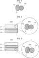
- Fig. 1 is a cross-sectional view illustrating a schematic configuration of an electrode material 1000 according to Embodiment 1.
- the electrode material 1000 in Embodiment 1 includes a first solid electrolyte particle 100, an electrode active material particle 110, and a coating layer 111.
- the electrode active material particle 110 and the first solid electrolyte particle 100 are separated from each other by the coating layer 111 and are not in direct contact with each other.
- the coating layer 111 is a layer including a coating material. That is, the coating layer 111 is provided on the surface of the electrode active material particle 110.
- the coating layer 111 may have a thickness of 1 nm or more and 100 nm or less.
- the coating layer 111 has a thickness of 1 nm or more, it is possible to prevent the electrode active material particle 110 and the first solid electrolyte particle 100 from direct contact to suppress the side reaction of the first solid electrolyte material. Consequently, the charge/discharge efficiency can be improved.
- the coating layer 111 has a thickness of 100 nm or less, the thickness of the coating layer 111 does not become too large. Accordingly, the internal resistance of the battery can be sufficiently reduced. As a result, the energy density of the battery can be increased.
- the coating layer 111 may uniformly coat the electrode active material particle 110. Direct contact between the electrode active material particle 110 and the first solid electrolyte particle 100 can be prevented to suppress the side reaction of the first solid electrolyte material. Consequently, the charge/discharge efficiency can be improved.
- the coating layer 111 may partially coat the electrode active material particle 110.
- a plurality of the electrode active material particles 110 are in direct contact with each other via the portion where the coating layer 111 is not present to improve the electron conductivity between the electrode active material particles 110. Consequently, high power operation of the battery is possible.
- the shape of the first solid electrolyte particle 100 in Embodiment 1 is not particularly limited and may be, for example, needle-like, spherical, or elliptical spherical.
- the median size may be 100 ⁇ m or less.
- the electrode active material particle 110 and the first solid electrolyte particle 100 can form a good dispersion state in the electrode material. Consequently, the charge/discharge characteristics is improved.
- the median size may be 10 ⁇ m or less.
- the electrode active material particle 110 and the first solid electrolyte particle 100 can form a good dispersion state.
- the first solid electrolyte particle 100 may be smaller than the median size of the electrode active material particle 110.
- the first solid electrolyte particle 100 and the electrode active material particle 110 can form a better dispersion state.
- the median size of the electrode active material particle 110 may be 0.1 ⁇ m or more and 100 ⁇ m or less.
- the electrode active material particle 110 has a median size of 0.1 ⁇ m or more, in the electrode material, the electrode active material particle 110 and the first solid electrolyte particle 100 can form a good dispersion state. As a result, the charge/discharge characteristics of the battery are improved. In addition, when the electrode active material particle 110 has a median size of 100 ⁇ m or less, the lithium diffusion in the electrode active material particle 110 is fast. Consequently, the battery can operate at high power.
- the median size of the electrode active material particle 110 may be larger than that of the first solid electrolyte particle 100. In such a case, the electrode active material particle 110 and the first solid electrolyte particle 100 can form a good dispersion state.
- the first solid electrolyte particle 100 and the coating layer 111 may be in contact with each other as shown in Fig. 1 .
- the electrode material 1000 in Embodiment 1 may include multiple first solid electrolyte particles 100 and multiple electrode active material particles 110.
- the content of the first solid electrolyte particle 100 and the content of the electrode active material particle 110 may be the same as or different from each other.
- the method for forming the coating layer 111 on the electrode active material particle 110 is not particularly limited.
- examples of the method include mechanical pulverization and mixing of the electrode active material particle 110 and the coating layer 111.
- the mixing method may be either a dry method or a wet method. In particular, dry mixing can simply produce a coating layer.
- the electrode active material particle 110 is dispersed in a coating material solution of the coating layer 111 and is dried.
- the coating layer can be simply and uniformly formed.
- examples of the method include an evaporation method.
- the evaporation method may be either a CVD method or a PVD method.
- ALD method atomic layer deposition method
- sputtering method which is one type of the PVD method
- the combination of the material used as the coating layer 111 and the method for forming it on the electrode active material particle 110 is not limited to the above-described examples, and the coating layer 111 may be formed by another combination.
- the first solid electrolyte material in Embodiment 1 can be manufactured by, for example, the following method.
- Raw material powders of binary halides are prepared so as to have the mix proportion of a desired composition.
- LiCI and YCl 3 are prepared at a mole ratio of 3:1.
- the raw material powders are mixed, pulverized, and reacted with each other by a mechanochemical milling method.
- the raw material powders are sufficiently mixed and may be then sintered.
- the configuration of the crystalline phase (i.e., crystalline structure) in the solid electrolyte material can be determined by adjusting the reaction method between the raw material powders and the reaction conditions.
- Embodiment 2 will now be described. Description overlapping with the above-described Embodiment 1 will be appropriately omitted.
- Fig. 2 is a cross-sectional view illustrating a schematic configuration of a battery 2000 according to Embodiment 2.
- Fig. 3 is a cross-sectional view illustrating a schematic configuration of a battery 3000 according to Embodiment 2.
- the battery 2000 in Embodiment 2 includes a positive electrode 201, an electrolyte layer 202, and a negative electrode 203.
- At least one of the positive electrode 201 and the negative electrode 203 includes the electrode material (e.g., electrode material 1000) in Embodiment 1 described above.
- Fig. 2 shows the battery 2000 in which the positive electrode 201 includes the electrode material 1000
- Fig. 3 shows the battery 3000 in which the negative electrode 203 includes the electrode material 1000.
- the electrolyte layer 202 is disposed between the positive electrode 201 and the negative electrode 203.
- the charge/discharge efficiency of the battery can be improved.
- the electrode material in Embodiment 1 described above can be used as a negative electrode material or a positive electrode material. More preferably, the electrode material in Embodiment 1 described above can be used as the negative electrode material.
- the charge/discharge efficiency of the battery can be further improved.
- the volume ratio, "v : 100 - v", of the electrode active material particle 110 and the first solid electrolyte particle 100 included in the positive electrode 201 may satisfy 30 ⁇ v ⁇ 95.
- v ⁇ 30 is satisfied, a sufficient energy density of the battery can be secured.
- v ⁇ 95 is satisfied, operation at high power can be realized.
- the volume ratio, "v : 100 - v" of the electrode active material particle 110 and the first solid electrolyte particle 100 included in the negative electrode 203 may satisfy 30 ⁇ v ⁇ 95.
- v ⁇ 30 is satisfied, a sufficient energy density of the battery can be secured.
- v ⁇ 95 is satisfied, operation at high power may be difficult.
- the positive electrode 201 may have a thickness of 10 ⁇ m or more and 500 ⁇ m or less. Further, when the positive electrode 201 has a thickness of 10 ⁇ m or more, a sufficient energy density of the battery can be secured. Further, when the positive electrode 201 has a thickness of 500 ⁇ m or less, operation at high power can be realized.
- the negative electrode 203 may have a thickness of 10 ⁇ m or more and 500 ⁇ m or less. Further, when the negative electrode 203 has a thickness of 10 ⁇ m or more, a sufficient energy density of the battery can be secured. Further, when the negative electrode 203 has a thickness of 500 ⁇ m or less, operation at high power can be realized.
- the electrolyte layer 202 is a layer including an electrolyte material.
- the electrolyte material is, for example, a solid electrolyte material (i.e., second solid electrolyte material). That is, the electrolyte layer 202 may be a solid electrolyte layer.
- a halide solid electrolyte As the second solid electrolyte material included in the electrolyte layer 202, a halide solid electrolyte, a sulfide solid electrolyte, an oxide solid electrolyte, a polymer solid electrolyte, or a complex hydride solid electrolyte may be used.
- the first solid electrolyte material in Embodiment 1 described above may be used. That is, the electrolyte layer 202 may include the first solid electrolyte material in Embodiment 1 described above.
- the charge/discharge characteristics of the battery can be further improved.
- the second solid electrolyte material included in the electrolyte layer 202 may be a halide solid electrolyte material that is different from the first solid electrolyte material in Embodiment 1 described above. That is, the electrolyte layer 202 may include a halide solid electrolyte material that is different from the first solid electrolyte material in Embodiment 1 described above.
- the charge/discharge characteristics of the battery can be further improved.
- the sulfide solid electrolyte As the sulfide solid electrolyte, the sulfide solid electrolytes exemplified as the coating material in Embodiment 1 may be used.
- Li 2 S-P 2 S 5 Li 2 S-SiS 2 , Li 2 S-B 2 S 3 , Li 2 S-GeS 2 , Li 3.25 Ge 0.25 P 0.75 S 4 , or Li 10 GeP 2 S 12
- LiX X: F, Cl, Br, or I
- Li 2 O, MO q Li 2 O, MO q
- Li p MO q Li p MO q (M: any one of P, Si, Ge, B, Al, Ga, In, Fe, and Zn) (p, q: natural number) may be added to the above-mentioned sulfide solid electrolytes.
- the oxide solid electrolyte As the oxide solid electrolyte, the oxide solid electrolytes exemplified as the coating material in Embodiment 1 may be used.
- oxide solid electrolyte for example, a NASICON-type solid electrolyte represented by LiTi 2 (PO 4 ) 3 and element substitutes thereof, a (LaLi)TiO 3 -based perovskite solid electrolyte, a LISICON-type solid electrolyte represented by Li 14 ZnGe 4 O 16 , Li 4 SiO 4 , and LiGeO 4 and element substitutes thereof, a garnet-type solid electrolyte represented by Li 7 La 3 Zr 2 O 12 and element substitutes thereof, Li 3 N and H substitutes thereof, Li 3 PO 4 and N substitutes thereof, or glass or glass ceramic mainly made of a Li-B-O compound, such as LiBO 2 or Li 3 BO 3 , and containing Li 2 SO 4 , Li 2 CO 3 , or the like can be used.
- a Li-B-O compound such as LiBO 2 or Li 3 BO 3 , and containing Li 2 SO 4 , Li 2 CO 3 , or the like
- the polymer solid electrolyte As the polymer solid electrolyte, the polymer solid electrolytes exemplified as the coating material in Embodiment 1 may be used.
- the polymer solid electrolyte for example, a compound of a polymer compound and a lithium salt may be used.
- the polymer compound may have an ethylene oxide structure.
- a polymer compound having an ethylene oxide structure can contain a large amount of the lithium salt and can further enhance the ion conductivity.
- the lithium salt for example, LiPF 6 , LiBF 4 , LiSbF 6 , LiAsF 6 , LiSO 3 CF 3 , LiN(SO 2 CF 3 ) 2 , LiN(SO 2 C 2 F 5 ) 2 , LiN(SO 2 CF 3 )(SO 2 C 4 F 9 ), or LiC(SO 2 CF 3 ) 3 can be used.
- the lithium salt one lithium salt selected from the above may be used alone.
- a mixture of two or more lithium salts selected from the above may be used.
- LiBH 4 -LiI or LiBH 4 -P 2 S 5 can be used as the complex hydride solid electrolyte.
- the solid electrolyte layer may include a second solid electrolyte material as a main component. That is, the solid electrolyte layer may include the second solid electrolyte material, for example, at 50% by weight or more (50 wt% or more) based on the entire solid electrolyte layer.
- the charge/discharge characteristics of the battery can be further improved.
- the solid electrolyte layer may include the second solid electrolyte material, for example, at 70% by weight or more (70 wt% or more) based on the entire solid electrolyte layer.
- the charge/discharge characteristics of the battery can be further improved.
- the solid electrolyte layer including the second solid electrolyte material as the main component may further include inevitable impurities or starting materials, by-products, decomposition products, etc. used or produced in synthesis of the second solid electrolyte material.
- the solid electrolyte layer may include the second solid electrolyte material, for example, at 100% by weight (100 wt%) based on the entire solid electrolyte layer excluding inevitable impurities as contamination.
- the charge/discharge characteristics of the battery can be further improved.
- the solid electrolyte layer may be constituted of the second solid electrolyte material only.
- the solid electrolyte layer may include two or more of the materials mentioned as the second solid electrolyte material.
- the solid electrolyte layer may include a halide solid electrolyte material and a sulfide solid electrolyte material.
- the electrolyte layer 202 may have a thickness of 1 ⁇ m or more and 300 ⁇ m or less. When the electrolyte layer 202 has a thickness of 1 ⁇ m or more, the positive electrode 201 and the negative electrode 203 can be separated from each other. In addition, when the electrolyte layer 202 has a thickness of 300 ⁇ m or less, operation at high power can be realized.
- the positive electrode 201 and the negative electrode 203 may include a solid electrolyte material.
- the solid electrolyte material the solid electrolyte materials exemplified as the material constituting the electrolyte layer 202 may be used. According to the configuration above, the lithium ion conductivity in the positive electrode 201 and the negative electrode 203 can be enhanced, and high power operation of the battery is possible.
- At least one of the positive electrode 201, the electrolyte layer 202, and the negative electrode 203 may include a binder for improving the adhesion between particles.
- the binder is used for improving the binding properties of the material constituting the electrode.
- the binder include polyvinylidene fluoride, polytetrafluoroethylene, polyethylene, polypropylene, aramid resin, polyamide, polyimide, polyamideimide, polyacrylnitrile, polyacrylic acid, polyacrylic acid methyl ester, polyacrylic acid ethyl ester, polyacrylic acid hexyl ester, polymethacrylic acid, polymethacrylic acid methyl ester, polymethacrylic acid ethyl ester, polymethacrylic acid hexyl ester, polyvinyl acetate, polyvinyl pyrrolidone, polyether, polyether sulfone, hexafluoropolypropylene, styrene butadiene rubber
- a copolymer of two or more materials selected from the group consisting of tetrafluoroethylene, hexafluoroethylene, hexafluoropropylene, perfluoroalkyl vinyl ether, vinylidene fluoride, chlorotrifluoroethylene, ethylene, propylene, pentafluoropropylene, fluoromethyl vinyl ether, acrylic acid, and hexadiene can be used.
- a mixture of two or more selected from the above may be used as the binder.
- At least one of the positive electrode 201 and the negative electrode 203 may include a conductive assistant for enhancing the electron conductivity.
- a conductive assistant for example, graphites such as natural graphite and artificial graphite, carbon blacks such as acetylene black and Ketjen black, conductive fibers such as carbon fiber and metal fiber, carbon fluoride, metal powders such as aluminum, conductive whiskers such as zinc oxide and potassium titanate, conductive metal oxides such as titanium oxide, and conductive polymer compounds such as polyaniline, polypyrrole, and polythiophene can be used.
- a carbon conductive assistant is used, cost reduction can be achieved.
- the battery in Embodiment 2 can be configured as batteries of various shapes such as a coin type, a cylindrical type, a square type, a sheet type, a button type, a flat type, and a stacked type.
- the operation temperature of the battery is not particularly limited and may be -50°C to 100°C.
- the ion conductivity of the coating material of the coating layer 111 is improved with an increase in temperature. In particular, the ion conductivity is dramatically improved at temperature not lower than the melting point of the coating material of the coating layer 111, and high power operation of the battery can be achieved.
- raw material powders of LiCI and YCl 3 were weighed such that the mole ratio of LiCI : YCl 3 was 2.7 : 1.1. Subsequently, the powders were subjected to milling treatment with a planetary ball mill (P-5 type, manufactured by Fritsch) at 600 rpm for 25 hours to obtain a powder of a first solid electrolyte material Li 2.7 Y 1.1 Cl 6 .
- a planetary ball mill P-5 type, manufactured by Fritsch
- Li 2 S and P 2 S 5 were weighed such that the mole ratio of Li 2 S : P 2 S 5 was 75 : 25. These compounds were pulverized and mixed in a mortar. Subsequently, the mixture was subjected to milling treatment with a planetary ball mill (P-7 type, manufactured by Fritsch) at 510 rpm for 10 hours to provide a vitrified solid electrolyte. The provided vitrified solid electrolyte was heated at 270°C in an inert atmosphere for 2 hours. Consequently, Li 2 S-P 2 S 5 , which was a glass-ceramic solid electrolyte, was provided.
- P-7 type manufactured by Fritsch
- Li 2 S-P 2 S 5 coating layer on a negative electrode active material graphite
- a coating material Li 2 S-P 2 S 5
- a negative electrode active material graphite
- the first solid electrolyte material and the coated negative electrode active material in the inventive example 1-1 were weighed such that the weight proportion of the negative electrode active material (graphite) was 40 wt%. These materials were mixed in an agate mortar to produce a negative electrode material of the inventive example 1-1.
- the coating material (Li 2 S-P 2 S 5 ) of the inventive example 1-1 and a negative electrode active material (graphite) were weighed at a weight ratio of 1 : 2. These materials were mixed in an agate mortar to provide a coated negative electrode active material.
- a negative electrode material of the inventive example 1-2 was provided by the same method as in the inventive example 1-1, except for the production of the negative electrode active material-coating layer.
- the coating material (Li 2 S-P 2 S 5 ) of the inventive example 1-1 and a negative electrode active material (graphite) were weighed at a weight ratio of 1 : 8. These materials were mixed in an agate mortar to provide a coated negative electrode active material.
- a negative electrode material of the inventive example 1-3 was provided by the same method as in the inventive example 1-1, except for the production of the negative electrode active material-coating layer.
- raw material powders of LiCI, YCl 3 , and ZrCl 4 were weighed such that the mole ratio of LiCI : YCl 3 : ZrCl 4 was 5 : 1 : 1. Subsequently, the powders were subjected to milling treatment with a planetary ball mill (P-5 type, manufactured by Fritsch) at 600 rpm for 25 hours to provide a powder of a first solid electrolyte material Li 2.5 Zr 0.5 Y 0.5 Cl 6 .
- P-5 type manufactured by Fritsch
- the first solid electrolyte material of the inventive example 1-4 and the coated negative electrode active material of the inventive example 1-1 were weighed such that the weight proportion of the negative electrode active material (graphite) was 40 wt%. These materials were mixed in an agate mortar to produce a negative electrode material of the inventive example 1-4.
- raw material powders of LiBr, Lil, YCl 3 , and YBr 3 were weighed such that the mole ratio of LiBr : LiI : YCl 3 : YBr 3 was 3 : 6 : 2 : 1. Subsequently, the powders were subjected to milling treatment with a planetary ball mill (P-5 type, manufactured by Fritsch) at 600 rpm for 25 hours to provide a powder of a first solid electrolyte material Li 3 YBr 2 Cl 2 I 2 .
- a planetary ball mill P-5 type, manufactured by Fritsch
- the first solid electrolyte material of the inventive example 1-5 and the coated negative electrode active material of the inventive example 1-1 were weighed such that the weight proportion of the negative electrode active material (graphite) was 40 wt%. These materials were mixed with an agate mortar to produce a negative electrode material of the inventive example 1-5.
- a negative electrode material of the comparative example 1-1 was provided by the same method as in the inventive example 1-1, except that the negative electrode active material-coating layer was not produced, and graphite on which the coating layer was not formed was used.
- a negative electrode material of the comparative example 1-2 was provided by the same method as in the inventive example 1-4, except that the negative electrode active material-coating layer was not produced, and graphite on which the coating layer was not formed was used.
- a negative electrode material of The comparative example 1-3 was prepared by the same method as in the inventive example 1-5, except that the negative electrode active material-coating layer was not produced, and graphite on which the coating layer was not formed was used.
- the negative electrode materials of the inventive examples 1-1 to 1-5 and The comparative examples 1-1 to 1-3 described above were evaluated using electrochemical cells.
- Li 2 S-P 2 S 5 and 12 mg of the negative electrode material were stacked in this order in an insulating outer cylinder, and then, were pressure-molded with a pressure of 370 MPa to provide a negative electrode and a solid electrolyte layer.
- a metal In (thickness: 200 ⁇ m), a metal Li (thickness: 300 ⁇ m), and a metal In (thickness: 200 ⁇ m) were stacked in this order on a surface of the solid electrolyte layer opposite to a surface in contact with the negative electrode, and then, were pressure-molded with a pressure of 80 MPa to form a bipolar electrochemical cell composed of the negative electrode (working electrode), the solid electrolyte layer, and a counter electrode.
- the electrochemical cell was tied up with four bolts from the top and the bottom to apply a surface pressure of 150 MPa to the layered product composed of the negative electrode (working electrode), the solid electrolyte layer, and the counter electrode.
- batteries of the inventive examples 1-1 to 1-5 and the comparative examples 1-1 to 1-3 described above were each produced.
- a charge/discharge test was performed using each of the batteries of the inventive examples 1-1 to 1-5 and The comparative examples 1-1 to 1-3 described above under the following conditions.
- the battery was placed in a thermostat of 25°C.
- Constant-current charging was performed at a current value of 70 ⁇ A, which was 0.04C rate (24-hour rate) to the theoretical capacity of the negative electrode active material (graphite). The charge was terminated when a charging capacity reached 360 mAh/g (97% of the theoretical capacity, 372 mAh/g, of graphite).
- the results of the inventive examples 1-1 to 1-5 and the comparative examples 1-1 to 1-3shown in Table 1 demonstrate that the charge/discharge efficiency of a battery is improved by including a first solid electrolyte material represented by a compositional formula: Li ⁇ M ⁇ X ⁇ , where ⁇ , ⁇ , and ⁇ are values larger than 0; M includes at least one of metal elements other than Li and metalloid elements; and X is one or more elements selected from the group consisting of Cl, Br, and I, and providing a coating layer including a coating material on the surface of a negative electrode active material.
- a first solid electrolyte material represented by a compositional formula: Li ⁇ M ⁇ X ⁇ , where ⁇ , ⁇ , and ⁇ are values larger than 0
- M includes at least one of metal elements other than Li and metalloid elements
- X is one or more elements selected from the group consisting of Cl, Br, and I, and providing a coating layer including a coating material on the surface of a negative
- raw material powders of LiCI and YCl 3 were weighed such that the mole ratio of LiCI : YCl 3 was 2.7 : 1.1. Subsequently, the powders were subjected to milling treatment with a planetary ball mill (P-5 type, manufactured by Fritsch) at 600 rpm for 25 hours to prepare a powder of a first solid electrolyte material Li 2.7 Y 1.1 Cl 6 .
- a planetary ball mill P-5 type, manufactured by Fritsch
- a polymer compound polyethylene oxide (PEO, molecular weight: 4 ⁇ 10 6 ) and a lithium salt LiCF 3 SO 3 (i.e., LiTFS) were weighed such that the mole ratio of ethylene oxide unit: lithium salt was 10 : 1.
- the mixture was dissolved in acetonitrile to produce a polymer electrolyte PEO-LiTFS composite solution.
- a coating material (PEO-LiTFS) and a negative electrode active material (graphite) were weighed at a weight ratio of 1 : 8, and the graphite was added to the polymer electrolyte solution, followed by dispersion with an ultrasonic disperser and then mixing with a planetary centrifugal mixer (ARE-310, manufactured by THINKY) at 1600 rpm for 3 minutes. The resulting product was spread on a petri dish and was vacuum-dried at 70°C for 1 hour to provide a coated negative electrode active material.
- the first solid electrolyte material and the coated negative electrode active material of the inventive example 2-1 were weighed such that the negative electrode active material (graphite) was 40 wt% of the total amount. These materials were mixed in an agate mortar to produce a negative electrode material of the inventive example 2-1.
- the coating material PEO-LiTFS
- a negative electrode active material graphite
- a negative electrode material of the inventive example 2-2 was prepared by the same method as in the inventive example 2-1, except for the production of the negative electrode active material-coating layer.
- the coating material PEO-LiTFS
- a negative electrode active material graphite
- a negative electrode material of the inventive example 2-3 was prepared by the same method as in the inventive example 2-1, except for the production of the negative electrode active material-coating layer.
- a polymer compound polyethylene oxide (PEO, molecular weight: 4 ⁇ 10 6 ) and a lithium salt LiN(SO 2 CF 3 ) 2 (i.e., LiTFSI) were weighed such that the mole ratio of ethylene oxide unit: lithium salt was 10 : 1.
- the mixture was dissolved in acetonitrile to produce a polymer electrolyte PEO-LiTFSI composite solution.
- a coating material (PEO-LiTFSI) and a negative electrode active material (graphite) were weighed at a weight ratio of 1 : 8, and the graphite was added to the polymer electrolyte solution, followed by dispersion with an ultrasonic disperser and then mixing with a planetary centrifugal mixer (ARE-310, manufactured by THINKY) at 1600 rpm for 3 minutes. The resulting product was spread on a petri dish and was vacuum-dried at 70°C for 1 hour to prepare a coated negative electrode active material.
- the first solid electrolyte material of the inventive example 2-1 and the coated negative electrode active material of the inventive example 2-4 were weighed such that the negative electrode active material (graphite) was 40 wt% of the total amount. These materials were mixed in an agate mortar to produce a negative electrode material of the inventive example 2-4.
- a polymer compound polyethylene oxide (PEO, molecular weight: 4 ⁇ 10 6 ) and a lithium salt LiN(SO 2 F) 2 (i.e., LiFSI) were weighed such that the mole ratio of ethylene oxide unit: lithium salt was 10 : 1.
- the mixture was dissolved in acetonitrile to produce a polymer electrolyte PEO-LiFSI composite solution.
- a coating material (PEO-LiFSI) and a negative electrode active material (graphite) were weighed at a weight ratio of 1 : 8, and the graphite was added to the polymer electrolyte solution, followed by dispersion with an ultrasonic disperser and then mixing with a planetary centrifugal mixer (ARE-310, manufactured by THINKY) at 1600 rpm for 3 minutes. The resulting product was spread on a petri dish and was vacuum-dried at 70°C for 1 hour to provide a coated negative electrode active material.
- the first solid electrolyte material of the inventive example 2-1 and the coated negative electrode active material of the inventive example 2-5 were weighed such that the negative electrode active material (graphite) was 40 wt% of the total amount. These materials were mixed in an agate mortar to produce a negative electrode material of the inventive example 2-5.
- raw material powders of LiCI, YCl 3 and ZrCl 4 were weighed such that the mole ratio of LiCI : YCl 3 : ZrCl 4 was 5 : 1 : 1. Subsequently, the powders were subjected to milling treatment with a planetary ball mill (P-5 type, manufactured by Fritsch) at 600 rpm for 25 hours to provide a powder of a first solid electrolyte material Li 2.5 Zr 0.5 Y 0.5 Cl 6 .
- P-5 type manufactured by Fritsch
- the first solid electrolyte material of the inventive example 2-6 and the coated negative electrode active material of the inventive example 2-5 were weighed such that the weight proportion of the negative electrode active material (graphite) was 40 wt%. These materials were mixed in an agate mortar to produce a negative electrode material of the inventive example 2-6.
- a negative electrode material of The comparative example 2-1 was provided by the same method as in the inventive example 2-1, except that the negative electrode active material-coating layer was not produced, and graphite on which the coating layer was not formed was used.
- a negative electrode material of The comparative example 2-2 was provided by the same method as in the inventive example 2-6, except that the negative electrode active material-coating layer was not produced, and graphite on which the coating layer was not formed was used.
- Li 2 S and P 2 S 5 were weighed such that the mole ratio of Li 2 S : P 2 S 5 was 75 : 25. These compounds were pulverized and mixed in a mortar. Subsequently, the mixture was subjected to milling treatment with a planetary ball mill (P-7 type, manufactured by Fritsch) at 510 rpm for 10 hours to provide a vitrified solid electrolyte. The provided vitrified solid electrolyte was heated at 270°C in an inert atmosphere for 2 hours. Consequently, Li 2 S-P 2 S 5 , which was a glass-ceramic solid electrolyte, was provided.
- P-7 type manufactured by Fritsch
- the negative electrode materials of the inventive examples 2-1 to 2-6 and The comparative examples 2-1 and 2-2 described above were evaluated using electrochemical cells.
- Li 2 S-P 2 S 5 and 12 mg of the negative electrode material were stacked in this order in an insulating outer cylinder, and then, were pressure-molded with a pressure of 370 MPa to provide a negative electrode and a solid electrolyte layer.
- a metal In (thickness: 200 ⁇ m), a metal Li (thickness: 300 ⁇ m), and a metal In (thickness: 200 ⁇ m) were stacked in this order on a surface of the solid electrolyte layer opposite to a surface in contact with the negative electrode, and then, were pressure-molded with a pressure of 80 MPa to form a bipolar electrochemical cell composed of the negative electrode (working electrode), the solid electrolyte layer, and a counter electrode.
- the electrochemical cell was tied up with four bolts from the top and the bottom to apply a surface pressure of 150 MPa to the layered product composed of the negative electrode (working electrode), the solid electrolyte layer, and the counter electrode.
- a surface pressure of 150 MPa to the layered product composed of the negative electrode (working electrode), the solid electrolyte layer, and the counter electrode.
- a charge/discharge test was performed using each of the batteries of the inventive examples 2-1 to 2-6 and the comparative examples 2-1 and 2-2 described above under the following conditions.
- the battery was placed in a thermostat of 70°C.
- Constant-current charging was performed at a current value of 70 ⁇ A, which was 0.04C rate (24-hour rate) to the theoretical capacity of the negative electrode active material (graphite). The charge was terminated when a charging capacity reached 360 mAh/g (97% of the theoretical capacity, 372 mAh/g, of graphite).
- the results of the inventive examples 2-1 to 2-6 and the comparative examples 2-1 to 2-2 shown in Table 2 demonstrate that the charge/discharge efficiency of a battery is improved by including a first solid electrolyte material represented by a compositional formula: Li ⁇ M ⁇ X ⁇ , where ⁇ , ⁇ , and ⁇ are values larger than 0; M includes at least one of metal elements other than Li and metalloid elements; and X is one or more elements selected from the group consisting of Cl, Br, and I, and providing a coating layer including a coating material on the surface of a negative electrode active material.
- a first solid electrolyte material represented by a compositional formula: Li ⁇ M ⁇ X ⁇ , where ⁇ , ⁇ , and ⁇ are values larger than 0; M includes at least one of metal elements other than Li and metalloid elements; and X is one or more elements selected from the group consisting of Cl, Br, and I, and providing a coating layer including a coating material on the surface of a negative electrode active
- raw material powders of LiCI and YCl 3 were weighed such that the mole ratio of LiCI : YCl 3 was 2.7 : 1.1. Subsequently, the powders were subjected to milling treatment with a planetary ball mill (P-5 type, manufactured by Fritsch) at 600 rpm for 25 hours to provide a powder of a first solid electrolyte material Li 2.7 Y 1.1 Cl 6 .
- a planetary ball mill P-5 type, manufactured by Fritsch
- a film of Li 3 PO 4 was formed on a surface of a negative electrode active material (natural graphite) by an atomic layer deposition method (ALD method) to obtain a coated negative electrode active material.
- the first solid electrolyte material of the inventive example 3-1 and the coated negative electrode active material (graphite on which the coating layer was formed) of the inventive example 3-1 were weighed at a weight ratio of 40 : 60. These materials were mixed in an agate mortar to produce a negative electrode material of the inventive example 3-1.
- a film of Li 4 Ti 5 O 12 (hereinafter, written as LTO) was formed on a surface of a negative electrode active material (natural graphite) by a sputtering method to obtain a coated negative electrode active material.
- a negative electrode material of the inventive example 3-2 was provided by the same method as in the inventive example 3-1, except for the production of the negative electrode active material-coating layer.
- a film of SiO 2 was formed on a surface of a negative electrode active material (natural graphite) by a sputtering method to obtain a coated negative electrode active material.
- a negative electrode material of the inventive example 3-3 was provided by the same method as in the inventive example 3-1, except for the production of the negative electrode active material-coating layer.
- a negative electrode material of the comparative example 3-1 was provided by the same method as in the inventive example 3-1, except that the negative electrode active material-coating layer was not produced, and natural graphite not provided with a coating layer was used.
- Li 2 S and P 2 S 5 were weighed such that the mole ratio of Li 2 S : P 2 S 5 was 75 : 25. These compounds were pulverized and mixed in a mortar. Subsequently, the mixture was subjected to milling treatment with a planetary ball mill (P-7 type, manufactured by Fritsch) at 510 rpm for 10 hours to provide a vitrified solid electrolyte. The resulting vitrified solid electrolyte was heated at 270°C in an inert atmosphere for 2 hours. Consequently, Li 2 S-P 2 S 5 , which was a glass-ceramic solid electrolyte, was provided.
- P-7 type manufactured by Fritsch
- the negative electrode materials of the inventive examples 3-1 to 3-3 and the comparative example 3-1 described above were evaluated using electrochemical cells.
- a metal In (thickness: 200 ⁇ m), a metal Li (thickness: 300 ⁇ m), and a metal In (thickness: 200 ⁇ m) were stacked in this order on a surface of the solid electrolyte layer opposite to a surface in contact with the negative electrode, and then, were pressure-molded with a pressure of 80 MPa to form a bipolar electrochemical cell composed of the negative electrode (working electrode), the solid electrolyte layer, and a counter electrode.
- the electrochemical cell was tied up with four bolts from the top and the bottom to apply a surface pressure of 150 MPa to the layered product composed of the negative electrode (working electrode), the solid electrolyte layer, and the counter electrode.
- batteries of the inventive examples 3-1 to 3-3 and the comparative example 3-1 described above were each produced.
- a charge/discharge test was performed using each of the batteries of the inventive examples 3-1 to 3-3 and the comparative example 3-1 described above under the following conditions.
- the battery was placed in a thermostat of 70°C.
- Constant-current charging was performed at a current value of 70 ⁇ A, which was 0.04C rate (24-hour rate). The charge was terminated when a charging capacity reached 360 mAh/g (97% of the theoretical capacity, 372 mAh/g, of graphite).
- the results of the inventive examples 3-1 to 3-3 and the comparative example 3-1 shown in Table 3 demonstrate that the charge/discharge efficiency of a battery is improved by including a first solid electrolyte material represented by a compositional formula: Li ⁇ M ⁇ X ⁇ , where ⁇ , ⁇ , and ⁇ are values larger than 0; M includes at least one of metal elements other than Li and metalloid elements; and X is one or more elements selected from the group consisting of Cl, Br, and I, and providing a coating layer including a coating material on a surface of a negative electrode active material.
- a first solid electrolyte material represented by a compositional formula: Li ⁇ M ⁇ X ⁇ , where ⁇ , ⁇ , and ⁇ are values larger than 0; M includes at least one of metal elements other than Li and metalloid elements; and X is one or more elements selected from the group consisting of Cl, Br, and I, and providing a coating layer including a coating material on a surface of a negative electrode active material
- the battery of the present disclosure can be used, for example, as an all-solid lithium secondary battery.
Claims (23)
- Matériau d'électrode comprenant :un matériau actif d'électrode ;un premier matériau d'électrolyte solide ; etun matériau de revêtement,dans lequelle premier matériau d'électrolyte solide inclut Li, M et X ;
oùM inclut au moins un sélectionné à partir d'un groupe consistant en des éléments métalliques autres que le Li et des éléments métalloïdes ; etX est au moins un sélectionné à partir du groupe constitué de Cl, Br et 1 ;le premier matériau d'électrolyte solide n'inclut pas le souffre ; etle matériau de revêtement est situé sur une surface du matériau actif d'électrode,dans lequelle premier matériau d'électrolyte solide est représenté par la formule de composition suivante (1) :
LiαMβXγ Formule (1)
où a, β et γ sont toutes des valeurs supérieures à 0 ; etM correspond au moins à un sélectionné à partir du groupe consistant en des éléments métalliques autres que Li et des éléments métalloïdes, et dans lequel M inclut l'yttrium. - Le matériau d'électrode selon la revendication 1, dans lequel
2 ≤ γ/α ≤ 2,4 est satisfait. - Le matériau d'électrode selon l'une quelconque de la revendication 1 ou 2, dans lequel X inclut le chlore.
- Le matériau d'électrode selon l'une quelconque des revendications 1 à 3, dans lequel


- Le matériau d'électrode selon l'une quelconque des revendications 1 à 4, dans lequel
le matériau de revêtement est un électrolyte solide de sulfure. - Le matériau d'électrode selon la revendication 5, dans lequel
l'électrolyte solide de sulfure inclut le sulfure de lithium et le sulfure de phosphore. - Le matériau d'électrode selon la revendication 5, dans lequel
l'électrolyte solide de sulfure correspond à Li2S-P2S5. - Le matériau d'électrode selon l'une quelconque des revendications 1 à 3, dans lequel


- Le matériau d'électrode selon l'une quelconque des revendications 1 à 3 et 8, dans lequel
le matériau de revêtement est un électrolyte solide polymère. - Le matériau d'électrode selon la revendication 9, dans lequel
l'électrolyte solide polymère est un composant composite d'oxyde de polyéthylène et d'un sel de lithium. - Le matériau d'électrode selon la revendication 10, dans lequel
le sel de lithium est un bis(trifluorométhanesulfonyl)imidure de lithium. - Le matériau d'électrode selon l'une quelconque des revendications 1 à 3, dans lequel


- Le matériau d'électrode selon l'une quelconque des revendications 1 à 3, et 12 dans lequel
le matériau de revêtement est un matériau d'oxyde. - Le matériau d'électrode selon la revendication 13, dans lequel
le matériau d'oxyde est un électrolyte solide d'oxyde ou un électrolyte solide d'oxynitrure. - Le matériau d'électrode selon la revendication 14, dans lequel
l'électrolyte solide d'oxyde est un phosphate de trilithium. - Le matériau d'électrode selon l'une quelconque des revendications 1 à 15, dans lequel
le matériau actif d'électrode est le graphite. - Le matériau d'électrode selon l'une quelconque des revendications 1 à 16, dans lequel
le matériau actif d'électrode est un matériau actif d'électrode positive. - Le matériau d'électrode selon l'une quelconque des revendications 1 à 16, dans lequel
le matériau actif d'électrode est un matériau actif d'électrode négative. - Batterie comprenant :une électrode positive ;une électrode négative ; etune couche d'électrolyte disposée entre l'électrode positive et l'électrode négative, dans laquelleau moins une de l'électrode positive et l'électrode négative inclut le matériau d'électrode selon l'une quelconque des revendications 1 à 17.
- La batterie selon la revendication 19, dans laquelle
une électrode négative inclut le matériau d'électrode selon l'une quelconque des revendications 1 à 17. - La batterie selon la revendication 19, dans laquelle
une électrode positive inclut le matériau d'électrode selon l'une quelconque des revendications 1 à 17. - La batterie selon l'une quelconque des revendications 19 à 21, dans laquelle
la couche d'électrolyte inclut le premier matériau d'électrolyte solide. - La batterie selon l'une quelconque des revendications 19 à 22, dans laquelle
la couche d'électrolyte inclut un matériau d'électrolyte solide à base d'halogénure différent du premier matériau d'électrolyte solide.
Priority Applications (1)
| Application Number | Priority Date | Filing Date | Title |
|---|---|---|---|
| EP23160124.6A EP4220756A1 (fr) | 2018-01-26 | 2018-12-17 | Matériau d'électrode et batterie |
Applications Claiming Priority (5)
| Application Number | Priority Date | Filing Date | Title |
|---|---|---|---|
| JP2018011532 | 2018-01-26 | ||
| JP2018011531 | 2018-01-26 | ||
| JP2018011524 | 2018-01-26 | ||
| JP2018173449 | 2018-09-18 | ||
| PCT/JP2018/046261 WO2019146308A1 (fr) | 2018-01-26 | 2018-12-17 | Matériau d'électrode et batterie |
Related Child Applications (2)
| Application Number | Title | Priority Date | Filing Date |
|---|---|---|---|
| EP23160124.6A Division-Into EP4220756A1 (fr) | 2018-01-26 | 2018-12-17 | Matériau d'électrode et batterie |
| EP23160124.6A Division EP4220756A1 (fr) | 2018-01-26 | 2018-12-17 | Matériau d'électrode et batterie |
Publications (3)
| Publication Number | Publication Date |
|---|---|
| EP3745504A1 EP3745504A1 (fr) | 2020-12-02 |
| EP3745504A4 EP3745504A4 (fr) | 2021-03-03 |
| EP3745504B1 true EP3745504B1 (fr) | 2023-07-12 |
Family
ID=67395604
Family Applications (2)
| Application Number | Title | Priority Date | Filing Date |
|---|---|---|---|
| EP18902418.5A Active EP3745504B1 (fr) | 2018-01-26 | 2018-12-17 | Matériau d'électrode et batterie |
| EP23160124.6A Pending EP4220756A1 (fr) | 2018-01-26 | 2018-12-17 | Matériau d'électrode et batterie |
Family Applications After (1)
| Application Number | Title | Priority Date | Filing Date |
|---|---|---|---|
| EP23160124.6A Pending EP4220756A1 (fr) | 2018-01-26 | 2018-12-17 | Matériau d'électrode et batterie |
Country Status (5)
| Country | Link |
|---|---|
| US (2) | US11777092B2 (fr) |
| EP (2) | EP3745504B1 (fr) |
| JP (1) | JP7349645B2 (fr) |
| CN (1) | CN111201643A (fr) |
| WO (1) | WO2019146308A1 (fr) |
Families Citing this family (24)
| Publication number | Priority date | Publication date | Assignee | Title |
|---|---|---|---|---|
| JP7316571B2 (ja) | 2018-01-05 | 2023-07-28 | パナソニックIpマネジメント株式会社 | 固体電解質材料、および、電池 |
| FR3080957B1 (fr) * | 2018-05-07 | 2020-07-10 | I-Ten | Electrodes mesoporeuses pour dispositifs electrochimiques en couches minces |
| CN110931730B (zh) * | 2019-11-04 | 2022-08-02 | 浙江锋锂新能源科技有限公司 | 一种铌酸钛负极材料及其制备方法和应用 |
| WO2021153018A1 (fr) * | 2020-01-29 | 2021-08-05 | パナソニックIpマネジメント株式会社 | Matériau d'électrolyte solide et batterie l'utilisant |
| CN114930593A (zh) * | 2020-01-29 | 2022-08-19 | 松下知识产权经营株式会社 | 固体电解质材料及使用了它的电池 |
| WO2021157361A1 (fr) * | 2020-02-05 | 2021-08-12 | パナソニック株式会社 | Matériau d'électrode positive et batterie |
| US20230143121A1 (en) * | 2020-03-06 | 2023-05-11 | Toyota Jidosha Kabushiki Kaisha | Solid-state battery |
| CN115336036A (zh) * | 2020-04-09 | 2022-11-11 | 松下知识产权经营株式会社 | 正极材料和电池 |
| KR20230152805A (ko) | 2020-04-14 | 2023-11-03 | 세인트-고바인 세라믹스 앤드 플라스틱스, 인크. | 이온 전도성 재료, 이온 전도성 재료를 포함하는 전해질 및 형성 방법 |
| EP4101021A4 (fr) | 2020-04-14 | 2024-01-24 | Saint Gobain Ceramics | Matériau électrolytique et procédés de formation |
| EP4104232A1 (fr) | 2020-04-23 | 2022-12-21 | Saint-Gobain Ceramics&Plastics, Inc. | Couche conductrice d'ions et procédés de formation |
| JP7389277B2 (ja) | 2020-04-23 | 2023-11-29 | サン-ゴバン セラミックス アンド プラスティクス,インコーポレイティド | イオン伝導性層およびその形成方法 |
| EP4145555A4 (fr) * | 2020-04-28 | 2023-10-18 | Panasonic Intellectual Property Management Co., Ltd. | Matériau d'électrode positive et batterie |
| KR20230018415A (ko) * | 2020-05-29 | 2023-02-07 | 더 리젠츠 오브 더 유니버시티 오브 미시건 | 리튬 배터리 고속 충전을 위한 이온 전도성 코팅의 원자층 증착 |
| WO2022004397A1 (fr) * | 2020-06-29 | 2022-01-06 | パナソニックIpマネジメント株式会社 | Matériau d'électrode positive et batterie |
| KR102606795B1 (ko) | 2020-08-07 | 2023-11-29 | 세인트-고바인 세라믹스 앤드 플라스틱스, 인크. | 전해질 재료 및 형성 방법 |
| CN116097487A (zh) | 2021-05-17 | 2023-05-09 | 圣戈本陶瓷及塑料股份有限公司 | 电解质材料和形成方法 |
| WO2022254984A1 (fr) * | 2021-05-31 | 2022-12-08 | パナソニックIpマネジメント株式会社 | Matériau d'électrode positive, électrode positive et batterie |
| JPWO2022259819A1 (fr) * | 2021-06-07 | 2022-12-15 | ||
| JPWO2023008006A1 (fr) * | 2021-07-29 | 2023-02-02 | ||
| CN114243099B (zh) * | 2022-01-24 | 2023-09-19 | 蜂巢能源科技(无锡)有限公司 | 硫化物型电解质及其制备方法和应用 |
| WO2023153394A1 (fr) * | 2022-02-10 | 2023-08-17 | Tdk株式会社 | Électrode négative pour batterie à électrolyte solide, et batterie à électrolyte solide |
| CN114914422B (zh) * | 2022-05-19 | 2024-03-15 | 武汉理工大学 | 适用于硫化物全固态电池的复合负极、制备方法及锂电池 |
| WO2024071221A1 (fr) * | 2022-09-28 | 2024-04-04 | Tdk株式会社 | Batterie entièrement solide |
Family Cites Families (22)
| Publication number | Priority date | Publication date | Assignee | Title |
|---|---|---|---|---|
| JP2001015115A (ja) * | 1999-06-29 | 2001-01-19 | Kyocera Corp | リチウム二次電池 |
| US7491467B2 (en) * | 2002-12-17 | 2009-02-17 | Mitsubishi Chemical Corporation | Negative electrode for nonaqueous electrolyte secondary battery and nonaqueous electrolyte secondary battery using the same |
| AU2003289407A1 (en) * | 2002-12-17 | 2004-07-09 | Mitsubishi Chemical Corporation | Nonaqueous electrolyte secondary battery-use cathode and nonaqueous electrolyte secondary battery |
| JP5108205B2 (ja) | 2005-02-28 | 2012-12-26 | 国立大学法人静岡大学 | 全固体型リチウム二次電池 |
| JP5349427B2 (ja) | 2010-08-26 | 2013-11-20 | トヨタ自動車株式会社 | 硫化物固体電解質材料、正極体およびリチウム固体電池 |
| US9537137B2 (en) * | 2011-12-09 | 2017-01-03 | Toyota Jidosha Kabushiki Kaisha | Cathode active material, cathode active material layer, all solid state battery and producing method for cathode active material |
| KR101511822B1 (ko) * | 2012-05-30 | 2015-04-13 | 주식회사 엘지화학 | 리튬 이차전지용 음극 활물질 및 이를 포함하는 리튬 이차전지 |
| WO2014073461A1 (fr) * | 2012-11-07 | 2014-05-15 | Semiconductor Energy Laboratory Co., Ltd. | Électrode pour dispositif de stockage d'électricité, dispositif de stockage d'électricité, et méthode de fabrication d'une électrode pour dispositif de stockage d'électricité |
| JP2014146458A (ja) * | 2013-01-28 | 2014-08-14 | Toyota Motor Corp | 全固体電池および電池システム |
| US9905851B2 (en) * | 2013-07-26 | 2018-02-27 | Lg Chem, Ltd. | Cathode active material and method of preparing the same |
| KR101785268B1 (ko) * | 2013-12-10 | 2017-10-16 | 삼성에스디아이 주식회사 | 음극 활물질, 이를 포함하는 리튬 전지 및 상기 음극 활물질의 제조방법 |
| JP6090249B2 (ja) | 2014-07-10 | 2017-03-08 | トヨタ自動車株式会社 | 複合活物質及びその製造方法 |
| WO2016035713A1 (fr) | 2014-09-05 | 2016-03-10 | 富士フイルム株式会社 | Pile rechargeable tout solide, composition d'électrolyte à l'état solide, feuille d'électrode de pile dans laquelle une composition d'électrolyte à l'état solide est utilisée, procédé de fabrication de feuille d'électrode de pile, et procédé de fabrication de pile rechargeable tout solide |
| US20160079597A1 (en) * | 2014-09-16 | 2016-03-17 | Samsung Electronics Co., Ltd. | All-solid lithium ion secondary battery |
| CN106058165B (zh) | 2015-04-02 | 2021-11-09 | 松下知识产权经营株式会社 | 电池和电池用电极材料 |
| JP6330719B2 (ja) | 2015-04-27 | 2018-05-30 | トヨタ自動車株式会社 | 負極活物質および全固体二次電池 |
| JP2017004910A (ja) * | 2015-06-16 | 2017-01-05 | 株式会社日立製作所 | リチウムイオン二次電池 |
| JP6840476B2 (ja) * | 2015-07-16 | 2021-03-10 | 株式会社半導体エネルギー研究所 | 蓄電装置の作製方法 |
| JP6536301B2 (ja) * | 2015-09-07 | 2019-07-03 | トヨタ自動車株式会社 | 被覆負極活物質 |
| JP2017111954A (ja) * | 2015-12-16 | 2017-06-22 | セイコーエプソン株式会社 | 金属酸化物成膜用組成物、正極複合体、正極複合体の製造方法、電池、および電池の製造方法 |
| JP7281771B2 (ja) | 2018-01-05 | 2023-05-26 | パナソニックIpマネジメント株式会社 | 正極材料、および、電池 |
| JPWO2020261757A1 (fr) * | 2019-06-26 | 2020-12-30 |
-
2018
- 2018-12-17 WO PCT/JP2018/046261 patent/WO2019146308A1/fr unknown
- 2018-12-17 EP EP18902418.5A patent/EP3745504B1/fr active Active
- 2018-12-17 EP EP23160124.6A patent/EP4220756A1/fr active Pending
- 2018-12-17 JP JP2019567911A patent/JP7349645B2/ja active Active
- 2018-12-17 CN CN201880064478.7A patent/CN111201643A/zh active Pending
-
2020
- 2020-07-15 US US16/929,289 patent/US11777092B2/en active Active
-
2023
- 2023-08-24 US US18/455,282 patent/US20230402607A1/en active Pending
Also Published As
| Publication number | Publication date |
|---|---|
| US11777092B2 (en) | 2023-10-03 |
| JP7349645B2 (ja) | 2023-09-25 |
| WO2019146308A1 (fr) | 2019-08-01 |
| US20200343554A1 (en) | 2020-10-29 |
| CN111201643A (zh) | 2020-05-26 |
| JPWO2019146308A1 (ja) | 2021-01-07 |
| US20230402607A1 (en) | 2023-12-14 |
| EP3745504A4 (fr) | 2021-03-03 |
| EP3745504A1 (fr) | 2020-12-02 |
| EP4220756A1 (fr) | 2023-08-02 |
Similar Documents
| Publication | Publication Date | Title |
|---|---|---|
| EP3745504B1 (fr) | Matériau d'électrode et batterie | |
| EP3745518B1 (fr) | Batterie | |
| EP3736892A1 (fr) | Matériau d'électrode positive et batterie | |
| JP7316564B2 (ja) | 電池 | |
| EP3745498B1 (fr) | Matériau d'électrode négative et batterie l'utilisant | |
| EP3745499A1 (fr) | Matériau d'électrode positive et batterie | |
| EP3736891A1 (fr) | Matériau d'électrode positive et batterie | |
| JP7145439B6 (ja) | 電池 | |
| EP4123754A1 (fr) | Matériau d'électrode positive, et batterie | |
| EP3745503A1 (fr) | Matériau d'électrode positive et batterie l'utilisant | |
| EP3745519B1 (fr) | Batterie | |
| EP3745508A1 (fr) | Matériau d'électrode positive et batterie utilisant celui-ci | |
| WO2020174868A1 (fr) | Matériau d'électrode positive, et batterie | |
| US20230042911A1 (en) | Positive electrode material and battery | |
| EP3890063A1 (fr) | Matériau d'électrode négative et batterie | |
| EP4141995A1 (fr) | Batterie | |
| CN111566848B (zh) | 负极材料和使用它的电池 | |
| CN117616600A (zh) | 正极材料及电池 |
Legal Events
| Date | Code | Title | Description |
|---|---|---|---|
| STAA | Information on the status of an ep patent application or granted ep patent |
Free format text: STATUS: THE INTERNATIONAL PUBLICATION HAS BEEN MADE |
|
| PUAI | Public reference made under article 153(3) epc to a published international application that has entered the european phase |
Free format text: ORIGINAL CODE: 0009012 |
|
| STAA | Information on the status of an ep patent application or granted ep patent |
Free format text: STATUS: REQUEST FOR EXAMINATION WAS MADE |
|
| 17P | Request for examination filed |
Effective date: 20200610 |
|
| AK | Designated contracting states |
Kind code of ref document: A1 Designated state(s): AL AT BE BG CH CY CZ DE DK EE ES FI FR GB GR HR HU IE IS IT LI LT LU LV MC MK MT NL NO PL PT RO RS SE SI SK SM TR |
|
| AX | Request for extension of the european patent |
Extension state: BA ME |
|
| A4 | Supplementary search report drawn up and despatched |
Effective date: 20210129 |
|
| RIC1 | Information provided on ipc code assigned before grant |
Ipc: H01M 4/133 20100101AFI20210125BHEP Ipc: H01M 10/052 20100101ALI20210125BHEP Ipc: H01M 4/36 20060101ALI20210125BHEP Ipc: H01M 10/0562 20100101ALI20210125BHEP Ipc: H01M 4/587 20100101ALI20210125BHEP Ipc: H01M 4/62 20060101ALI20210125BHEP Ipc: H01B 1/06 20060101ALI20210125BHEP |
|
| DAV | Request for validation of the european patent (deleted) | ||
| DAX | Request for extension of the european patent (deleted) | ||
| GRAP | Despatch of communication of intention to grant a patent |
Free format text: ORIGINAL CODE: EPIDOSNIGR1 |
|
| STAA | Information on the status of an ep patent application or granted ep patent |
Free format text: STATUS: GRANT OF PATENT IS INTENDED |
|
| INTG | Intention to grant announced |
Effective date: 20230210 |
|
| GRAS | Grant fee paid |
Free format text: ORIGINAL CODE: EPIDOSNIGR3 |
|
| GRAA | (expected) grant |
Free format text: ORIGINAL CODE: 0009210 |
|
| STAA | Information on the status of an ep patent application or granted ep patent |
Free format text: STATUS: THE PATENT HAS BEEN GRANTED |
|
| AK | Designated contracting states |
Kind code of ref document: B1 Designated state(s): AL AT BE BG CH CY CZ DE DK EE ES FI FR GB GR HR HU IE IS IT LI LT LU LV MC MK MT NL NO PL PT RO RS SE SI SK SM TR |
|
| REG | Reference to a national code |
Ref country code: CH Ref legal event code: EP |
|
| REG | Reference to a national code |
Ref country code: IE Ref legal event code: FG4D |
|
| REG | Reference to a national code |
Ref country code: DE Ref legal event code: R096 Ref document number: 602018053420 Country of ref document: DE |
|
| REG | Reference to a national code |
Ref country code: LT Ref legal event code: MG9D |
|
| REG | Reference to a national code |
Ref country code: NL Ref legal event code: MP Effective date: 20230712 |
|
| REG | Reference to a national code |
Ref country code: AT Ref legal event code: MK05 Ref document number: 1588069 Country of ref document: AT Kind code of ref document: T Effective date: 20230712 |
|
| PG25 | Lapsed in a contracting state [announced via postgrant information from national office to epo] |
Ref country code: NL Free format text: LAPSE BECAUSE OF FAILURE TO SUBMIT A TRANSLATION OF THE DESCRIPTION OR TO PAY THE FEE WITHIN THE PRESCRIBED TIME-LIMIT Effective date: 20230712 |
|
| PG25 | Lapsed in a contracting state [announced via postgrant information from national office to epo] |
Ref country code: GR Free format text: LAPSE BECAUSE OF FAILURE TO SUBMIT A TRANSLATION OF THE DESCRIPTION OR TO PAY THE FEE WITHIN THE PRESCRIBED TIME-LIMIT Effective date: 20231013 |
|
| PG25 | Lapsed in a contracting state [announced via postgrant information from national office to epo] |
Ref country code: ES Free format text: LAPSE BECAUSE OF FAILURE TO SUBMIT A TRANSLATION OF THE DESCRIPTION OR TO PAY THE FEE WITHIN THE PRESCRIBED TIME-LIMIT Effective date: 20230712 |
|
| PG25 | Lapsed in a contracting state [announced via postgrant information from national office to epo] |
Ref country code: IS Free format text: LAPSE BECAUSE OF FAILURE TO SUBMIT A TRANSLATION OF THE DESCRIPTION OR TO PAY THE FEE WITHIN THE PRESCRIBED TIME-LIMIT Effective date: 20231112 |
|
| PG25 | Lapsed in a contracting state [announced via postgrant information from national office to epo] |
Ref country code: SE Free format text: LAPSE BECAUSE OF FAILURE TO SUBMIT A TRANSLATION OF THE DESCRIPTION OR TO PAY THE FEE WITHIN THE PRESCRIBED TIME-LIMIT Effective date: 20230712 Ref country code: RS Free format text: LAPSE BECAUSE OF FAILURE TO SUBMIT A TRANSLATION OF THE DESCRIPTION OR TO PAY THE FEE WITHIN THE PRESCRIBED TIME-LIMIT Effective date: 20230712 Ref country code: PT Free format text: LAPSE BECAUSE OF FAILURE TO SUBMIT A TRANSLATION OF THE DESCRIPTION OR TO PAY THE FEE WITHIN THE PRESCRIBED TIME-LIMIT Effective date: 20231113 Ref country code: NO Free format text: LAPSE BECAUSE OF FAILURE TO SUBMIT A TRANSLATION OF THE DESCRIPTION OR TO PAY THE FEE WITHIN THE PRESCRIBED TIME-LIMIT Effective date: 20231012 Ref country code: LV Free format text: LAPSE BECAUSE OF FAILURE TO SUBMIT A TRANSLATION OF THE DESCRIPTION OR TO PAY THE FEE WITHIN THE PRESCRIBED TIME-LIMIT Effective date: 20230712 Ref country code: LT Free format text: LAPSE BECAUSE OF FAILURE TO SUBMIT A TRANSLATION OF THE DESCRIPTION OR TO PAY THE FEE WITHIN THE PRESCRIBED TIME-LIMIT Effective date: 20230712 Ref country code: IS Free format text: LAPSE BECAUSE OF FAILURE TO SUBMIT A TRANSLATION OF THE DESCRIPTION OR TO PAY THE FEE WITHIN THE PRESCRIBED TIME-LIMIT Effective date: 20231112 Ref country code: HR Free format text: LAPSE BECAUSE OF FAILURE TO SUBMIT A TRANSLATION OF THE DESCRIPTION OR TO PAY THE FEE WITHIN THE PRESCRIBED TIME-LIMIT Effective date: 20230712 Ref country code: GR Free format text: LAPSE BECAUSE OF FAILURE TO SUBMIT A TRANSLATION OF THE DESCRIPTION OR TO PAY THE FEE WITHIN THE PRESCRIBED TIME-LIMIT Effective date: 20231013 Ref country code: FI Free format text: LAPSE BECAUSE OF FAILURE TO SUBMIT A TRANSLATION OF THE DESCRIPTION OR TO PAY THE FEE WITHIN THE PRESCRIBED TIME-LIMIT Effective date: 20230712 Ref country code: ES Free format text: LAPSE BECAUSE OF FAILURE TO SUBMIT A TRANSLATION OF THE DESCRIPTION OR TO PAY THE FEE WITHIN THE PRESCRIBED TIME-LIMIT Effective date: 20230712 Ref country code: AT Free format text: LAPSE BECAUSE OF FAILURE TO SUBMIT A TRANSLATION OF THE DESCRIPTION OR TO PAY THE FEE WITHIN THE PRESCRIBED TIME-LIMIT Effective date: 20230712 |
|
| PGFP | Annual fee paid to national office [announced via postgrant information from national office to epo] |
Ref country code: DE Payment date: 20231214 Year of fee payment: 6 |
|
| PG25 | Lapsed in a contracting state [announced via postgrant information from national office to epo] |
Ref country code: PL Free format text: LAPSE BECAUSE OF FAILURE TO SUBMIT A TRANSLATION OF THE DESCRIPTION OR TO PAY THE FEE WITHIN THE PRESCRIBED TIME-LIMIT Effective date: 20230712 |
|
| PG25 | Lapsed in a contracting state [announced via postgrant information from national office to epo] |
Ref country code: SM Free format text: LAPSE BECAUSE OF FAILURE TO SUBMIT A TRANSLATION OF THE DESCRIPTION OR TO PAY THE FEE WITHIN THE PRESCRIBED TIME-LIMIT Effective date: 20230712 Ref country code: RO Free format text: LAPSE BECAUSE OF FAILURE TO SUBMIT A TRANSLATION OF THE DESCRIPTION OR TO PAY THE FEE WITHIN THE PRESCRIBED TIME-LIMIT Effective date: 20230712 Ref country code: EE Free format text: LAPSE BECAUSE OF FAILURE TO SUBMIT A TRANSLATION OF THE DESCRIPTION OR TO PAY THE FEE WITHIN THE PRESCRIBED TIME-LIMIT Effective date: 20230712 Ref country code: DK Free format text: LAPSE BECAUSE OF FAILURE TO SUBMIT A TRANSLATION OF THE DESCRIPTION OR TO PAY THE FEE WITHIN THE PRESCRIBED TIME-LIMIT Effective date: 20230712 Ref country code: CZ Free format text: LAPSE BECAUSE OF FAILURE TO SUBMIT A TRANSLATION OF THE DESCRIPTION OR TO PAY THE FEE WITHIN THE PRESCRIBED TIME-LIMIT Effective date: 20230712 Ref country code: SK Free format text: LAPSE BECAUSE OF FAILURE TO SUBMIT A TRANSLATION OF THE DESCRIPTION OR TO PAY THE FEE WITHIN THE PRESCRIBED TIME-LIMIT Effective date: 20230712 |