WO2021157361A1 - Matériau d'électrode positive et batterie - Google Patents
Matériau d'électrode positive et batterie Download PDFInfo
- Publication number
- WO2021157361A1 WO2021157361A1 PCT/JP2021/001901 JP2021001901W WO2021157361A1 WO 2021157361 A1 WO2021157361 A1 WO 2021157361A1 JP 2021001901 W JP2021001901 W JP 2021001901W WO 2021157361 A1 WO2021157361 A1 WO 2021157361A1
- Authority
- WO
- WIPO (PCT)
- Prior art keywords
- solid electrolyte
- positive electrode
- battery
- active material
- electrode active
- Prior art date
Links
Images


Classifications
-
- H—ELECTRICITY
- H01—ELECTRIC ELEMENTS
- H01M—PROCESSES OR MEANS, e.g. BATTERIES, FOR THE DIRECT CONVERSION OF CHEMICAL ENERGY INTO ELECTRICAL ENERGY
- H01M4/00—Electrodes
- H01M4/02—Electrodes composed of, or comprising, active material
- H01M4/13—Electrodes for accumulators with non-aqueous electrolyte, e.g. for lithium-accumulators; Processes of manufacture thereof
- H01M4/131—Electrodes based on mixed oxides or hydroxides, or on mixtures of oxides or hydroxides, e.g. LiCoOx
-
- H—ELECTRICITY
- H01—ELECTRIC ELEMENTS
- H01M—PROCESSES OR MEANS, e.g. BATTERIES, FOR THE DIRECT CONVERSION OF CHEMICAL ENERGY INTO ELECTRICAL ENERGY
- H01M10/00—Secondary cells; Manufacture thereof
- H01M10/05—Accumulators with non-aqueous electrolyte
- H01M10/052—Li-accumulators
- H01M10/0525—Rocking-chair batteries, i.e. batteries with lithium insertion or intercalation in both electrodes; Lithium-ion batteries
-
- H—ELECTRICITY
- H01—ELECTRIC ELEMENTS
- H01M—PROCESSES OR MEANS, e.g. BATTERIES, FOR THE DIRECT CONVERSION OF CHEMICAL ENERGY INTO ELECTRICAL ENERGY
- H01M10/00—Secondary cells; Manufacture thereof
- H01M10/05—Accumulators with non-aqueous electrolyte
- H01M10/056—Accumulators with non-aqueous electrolyte characterised by the materials used as electrolytes, e.g. mixed inorganic/organic electrolytes
- H01M10/0561—Accumulators with non-aqueous electrolyte characterised by the materials used as electrolytes, e.g. mixed inorganic/organic electrolytes the electrolyte being constituted of inorganic materials only
- H01M10/0562—Solid materials
-
- H—ELECTRICITY
- H01—ELECTRIC ELEMENTS
- H01M—PROCESSES OR MEANS, e.g. BATTERIES, FOR THE DIRECT CONVERSION OF CHEMICAL ENERGY INTO ELECTRICAL ENERGY
- H01M4/00—Electrodes
- H01M4/02—Electrodes composed of, or comprising, active material
- H01M4/36—Selection of substances as active materials, active masses, active liquids
- H01M4/48—Selection of substances as active materials, active masses, active liquids of inorganic oxides or hydroxides
- H01M4/50—Selection of substances as active materials, active masses, active liquids of inorganic oxides or hydroxides of manganese
- H01M4/505—Selection of substances as active materials, active masses, active liquids of inorganic oxides or hydroxides of manganese of mixed oxides or hydroxides containing manganese for inserting or intercalating light metals, e.g. LiMn2O4 or LiMn2OxFy
-
- H—ELECTRICITY
- H01—ELECTRIC ELEMENTS
- H01M—PROCESSES OR MEANS, e.g. BATTERIES, FOR THE DIRECT CONVERSION OF CHEMICAL ENERGY INTO ELECTRICAL ENERGY
- H01M4/00—Electrodes
- H01M4/02—Electrodes composed of, or comprising, active material
- H01M4/36—Selection of substances as active materials, active masses, active liquids
- H01M4/48—Selection of substances as active materials, active masses, active liquids of inorganic oxides or hydroxides
- H01M4/52—Selection of substances as active materials, active masses, active liquids of inorganic oxides or hydroxides of nickel, cobalt or iron
- H01M4/525—Selection of substances as active materials, active masses, active liquids of inorganic oxides or hydroxides of nickel, cobalt or iron of mixed oxides or hydroxides containing iron, cobalt or nickel for inserting or intercalating light metals, e.g. LiNiO2, LiCoO2 or LiCoOxFy
-
- H—ELECTRICITY
- H01—ELECTRIC ELEMENTS
- H01M—PROCESSES OR MEANS, e.g. BATTERIES, FOR THE DIRECT CONVERSION OF CHEMICAL ENERGY INTO ELECTRICAL ENERGY
- H01M4/00—Electrodes
- H01M4/02—Electrodes composed of, or comprising, active material
- H01M4/62—Selection of inactive substances as ingredients for active masses, e.g. binders, fillers
-
- H—ELECTRICITY
- H01—ELECTRIC ELEMENTS
- H01M—PROCESSES OR MEANS, e.g. BATTERIES, FOR THE DIRECT CONVERSION OF CHEMICAL ENERGY INTO ELECTRICAL ENERGY
- H01M4/00—Electrodes
- H01M4/02—Electrodes composed of, or comprising, active material
- H01M2004/026—Electrodes composed of, or comprising, active material characterised by the polarity
- H01M2004/028—Positive electrodes
-
- H—ELECTRICITY
- H01—ELECTRIC ELEMENTS
- H01M—PROCESSES OR MEANS, e.g. BATTERIES, FOR THE DIRECT CONVERSION OF CHEMICAL ENERGY INTO ELECTRICAL ENERGY
- H01M2300/00—Electrolytes
- H01M2300/0017—Non-aqueous electrolytes
- H01M2300/0065—Solid electrolytes
- H01M2300/0068—Solid electrolytes inorganic
- H01M2300/008—Halides
-
- Y—GENERAL TAGGING OF NEW TECHNOLOGICAL DEVELOPMENTS; GENERAL TAGGING OF CROSS-SECTIONAL TECHNOLOGIES SPANNING OVER SEVERAL SECTIONS OF THE IPC; TECHNICAL SUBJECTS COVERED BY FORMER USPC CROSS-REFERENCE ART COLLECTIONS [XRACs] AND DIGESTS
- Y02—TECHNOLOGIES OR APPLICATIONS FOR MITIGATION OR ADAPTATION AGAINST CLIMATE CHANGE
- Y02E—REDUCTION OF GREENHOUSE GAS [GHG] EMISSIONS, RELATED TO ENERGY GENERATION, TRANSMISSION OR DISTRIBUTION
- Y02E60/00—Enabling technologies; Technologies with a potential or indirect contribution to GHG emissions mitigation
- Y02E60/10—Energy storage using batteries
Definitions
- the present disclosure relates to positive electrode materials for batteries and batteries.
- Patent Document 1 discloses an all-solid-state lithium battery using a positive electrode containing a sulfide solid electrolyte.
- Patent Document 2 discloses an all-solid-state lithium battery containing a halide solid electrolyte such as Li 3 YCl 6 and Li 3 YBr 6.
- the positive electrode material in one aspect of the present disclosure is Positive electrode active material and A first solid electrolyte containing a sulfide solid electrolyte, and Includes a second solid electrolyte, including a halide solid electrolyte,
- the ratio x of the volume of the second solid electrolyte to the total value of the volume of the first solid electrolyte and the volume of the second solid electrolyte satisfies 20 ⁇ x ⁇ 95 as a percentage.
- a positive electrode material capable of realizing a positive electrode having both high thermal stability and low interfacial resistance.
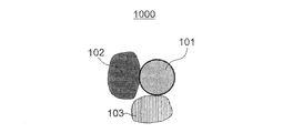
- FIG. 1 is a cross-sectional view showing a schematic configuration of a positive electrode material according to the first embodiment.
- FIG. 2 is a cross-sectional view showing a schematic configuration of the battery according to the second embodiment.
- FIG. 3 is a Nyquist diagram obtained by performing an AC impedance analysis on the battery of Comparative Example 3.
- FIG. 4 is a graph showing the relationship between the ratio x, the interfacial resistance, and the calorific value in Examples and Comparative Examples.
- the positive electrode material according to the first aspect of the present disclosure is Positive electrode active material and A first solid electrolyte containing a sulfide solid electrolyte, and Includes a second solid electrolyte, including a halide solid electrolyte,
- the ratio x of the volume of the second solid electrolyte to the total value of the volume of the first solid electrolyte and the volume of the second solid electrolyte satisfies 20 ⁇ x ⁇ 95 as a percentage.
- the positive electrode material can realize a positive electrode having both high thermal stability and low interfacial resistance.
- the ratio x may satisfy 35.2 ⁇ x ⁇ 76.5 as a percentage.
- the thermal stability of the positive electrode can be further improved and lower interfacial resistance can be realized.
- the halide solid electrolyte may be represented by the following composition formula (1).
- Li ⁇ M ⁇ X ⁇ ⁇ ⁇ ⁇ Equation (1) ⁇ , ⁇ and ⁇ may each have a value greater than 0, M may contain at least one selected from the group consisting of metal elements other than Li and metalloid elements, and X may contain. , F, Cl, Br and I may contain at least one selected from the group.
- the M may contain yttrium.
- the ionic conductivity of the halide solid electrolyte can be further improved.
- the positive electrode active material may contain a lithium-containing transition metal composite oxide.
- the positive electrode active material may contain lithium nickel cobalt manganate.
- the positive electrode material can further improve the energy density of the battery and the charge / discharge efficiency of the battery.
- the battery according to the eighth aspect of the present disclosure is A positive electrode containing a positive electrode material according to any one of the first to seventh aspects, and a positive electrode. With the negative electrode An electrolyte layer arranged between the positive electrode and the negative electrode, It has.
- high thermal stability and high output characteristics can be achieved at the same time in the battery.
- the electrolyte layer may contain the same material as the second solid electrolyte. According to the ninth aspect, the thermal stability of the battery can be further improved.
- the electrolyte layer contains a halide solid electrolyte different from the halide solid electrolyte contained in the second solid electrolyte. May be good. According to the tenth aspect, the thermal stability of the battery can be further improved.
- the electrolyte layer may contain a sulfide solid electrolyte. According to the eleventh aspect, the energy density of the battery can be improved.
- FIG. 1 is a cross-sectional view showing a schematic configuration of the positive electrode material 1000 according to the first embodiment.
- the positive electrode material 1000 includes a positive electrode active material 101, a first solid electrolyte 102, and a second solid electrolyte 103.
- the first solid electrolyte 102 contains a sulfide solid electrolyte.
- the first solid electrolyte 102 is, for example, substantially composed of only a sulfide solid electrolyte. By “substantially consisting of” is meant eliminating other components that alter the essential characteristics of the mentioned material. However, the first solid electrolyte 102 may contain impurities in addition to the sulfide solid electrolyte.
- the second solid electrolyte 103 contains a halide solid electrolyte.
- the second solid electrolyte 103 comprises, for example, substantially only the halide solid electrolyte. However, the second solid electrolyte 103 may contain impurities in addition to the halide solid electrolyte.
- the ratio x of the volume of the second solid electrolyte 103 to the total value of the volume of the first solid electrolyte 102 and the volume of the second solid electrolyte 103 satisfies 20 ⁇ x ⁇ 95 as a percentage.
- the positive electrode material 1000 can achieve both high thermal stability and low interfacial resistance.
- Patent Document 1 discloses an all-solid-state lithium battery using a positive electrode containing a sulfide solid electrolyte.
- Patent Document 2 discloses an all-solid-state lithium battery containing a halide solid electrolyte such as Li 3 YCl 6 and Li 3 YBr 6. Further, Patent Document 2 discloses that the positive electrode may contain a sulfide solid electrolyte for the purpose of improving ionic conductivity.
- Patent Documents 1 and 2 do not explicitly disclose a positive electrode containing both a halide solid electrolyte and a sulfide solid electrolyte. That is, Patent Documents 1 and 2 neither describe nor suggest the mixing ratio of the halide solid electrolyte and the sulfide solid electrolyte in the positive electrode material contained in the positive electrode.
- the positive electrode material contains a first solid electrolyte containing a sulfide solid electrolyte and a second solid electrolyte containing a halide solid electrolyte, and further, the volume of the first solid electrolyte.
- the ratio x of the volume of the second solid electrolyte to the total value of the volume of the second solid electrolyte and the volume of the second solid electrolyte satisfies 20 ⁇ x ⁇ 95 as a percentage, a positive electrode having both high thermal stability and low interfacial resistance is realized. I found something new that I could do.
- the thermal stability of the positive electrode containing the solid electrolyte is greatly affected by the thermal stability of the solid electrolyte itself and the reactivity of the solid electrolyte with the oxygen released from the positive electrode.
- the positive electrode active material when the positive electrode active material contains oxygen, when the battery is charged, the structure of the positive electrode active material becomes unstable, and oxygen may be released from the positive electrode active material.
- the positive electrode active material when the battery generates heat due to an excessive current flowing through the battery due to a short circuit or the like, the positive electrode active material is heated and oxygen is likely to be released.
- the positive electrode active material is further heated using the reaction heat as a heat source.
- the oxidation reaction of the solid electrolyte may proceed at an accelerated rate.
- a solid electrolyte having high thermal stability and a small amount of heat generated by the oxidation reaction.
- the halide solid electrolyte is not only superior in thermal stability of the solid electrolyte itself as compared with the sulfide solid electrolyte, but also has low reactivity with oxygen, and the amount of heat generated by the oxidation reaction is small. I found a new thing that is small. Therefore, when the positive electrode material contains a halide solid electrolyte and a sulfide solid electrolyte, the higher the volume ratio of the halide solid electrolyte, the better the thermal stability of the positive electrode including the positive electrode material.
- the ratio (ratio x) of the volume of the halide solid electrolyte to the total volume of these solid electrolytes is 20 vol% or more, the reaction between the sulfide solid electrolyte and the oxygen released from the positive electrode active material. Can be sufficiently suppressed. As a result, the amount of heat generated by the oxidation reaction of the sulfide solid electrolyte can be sufficiently reduced, and the thermal stability of the positive electrode can be improved.
- the ratio x may be 20 vol% or more.
- the positive electrode active material contained in the positive electrode material and the solid electrolyte must be closely bonded.
- a load is usually applied to a positive electrode material containing a positive electrode active material and a solid electrolyte to bond the positive electrode active material and the solid electrolyte.
- the Young's modulus of the solid electrolyte is low and the deformability of the solid electrolyte is high, the solid electrolyte is likely to be closely bonded to the positive electrode active material.
- the sulfide solid electrolyte has a lower Young's modulus and higher deformability than the halide solid electrolyte. Therefore, when the positive electrode material contains a sulfide solid electrolyte, low interfacial resistance can be realized by closely bonding the positive electrode active material and the sulfide solid electrolyte. That is, when the positive electrode material contains a sulfide solid electrolyte and a halide solid electrolyte, the higher the volume ratio of the sulfide solid electrolyte, the lower the interfacial resistance is realized in the positive electrode.
- the lower the volume ratio of the halide solid electrolyte the lower the interfacial resistance is achieved at the positive electrode.
- the ratio (ratio x) of the volume of the halide solid electrolyte to the total value of the volumes of these solid electrolytes is 95 vol% or less, the area where the positive electrode active material and the sulfide solid electrolyte come into contact with each other is sufficient. Can be secured. Thereby, the interfacial resistance in the positive electrode can be reduced.
- the ratio x may be 95 vol% or less.
- the above ratio x may satisfy 30 ⁇ x ⁇ 95 as a percentage, or may satisfy 35.2 ⁇ x ⁇ 76.5.
- the ratio x may satisfy 48.4 ⁇ x ⁇ 84.9 as a percentage.
- the thermal stability of the positive electrode containing the positive electrode material 1000 can be further improved, and a positive electrode having a lower interfacial resistance can be realized.
- the halide solid electrolyte contained in the second solid electrolyte 103 may be represented by the following composition formula (1).
- ⁇ , ⁇ , and ⁇ are values larger than 0, respectively.
- M contains at least one selected from the group consisting of metal elements other than Li and metalloid elements. M may be at least one element selected from the group consisting of metal elements other than Li and metalloid elements.
- X comprises at least one selected from the group consisting of F, Cl, Br and I.
- X may be at least one selected from the group consisting of F, Cl, Br and I.
- the ionic conductivity of the halide solid electrolyte can be further improved.
- the output characteristic of the battery can be further improved.
- the "metalloid element” is B, Si, Ge, As, Sb and Te.
- metal element refers to all elements contained in groups 1 to 12 of the periodic table except hydrogen, as well as B, Si, Ge, As, Sb, Te, C, N, P, and O.
- S and Se are all elements contained in groups 13 to 16 of the periodic table.
- the "metalloid element” or “metal element” is a group of elements that can become cations when a halogen compound and an inorganic compound are formed.
- M may contain Y (yttrium). That is, the halide solid electrolyte may contain Y as a metal element.
- the ionic conductivity of the halide solid electrolyte can be further improved.
- the output characteristic of the battery can be further improved.
- the halide solid electrolyte containing Y may be, for example, a compound represented by the composition formula of Li a Me b Y c X 6.
- Me is at least one selected from the group consisting of metal elements and metalloid elements excluding Li and Y.
- m is the valence of Me.
- X is at least one selected from the group consisting of F, Cl, Br and I.
- Me may be at least one selected from the group consisting of Mg, Ca, Sr, Ba, Zn, Sc, Al, Ga, Bi, Zr, Hf, Ti, Sn, Ta and Nb.
- the ionic conductivity of the halide solid electrolyte can be further improved.
- the halide solid electrolyte contained in the second solid electrolyte 103 may be represented by the following composition formula (A1).
- X is at least one selected from the group consisting of F, Cl, Br and I, or two or more elements selected from the group.
- composition formula (A1) d satisfies 0 ⁇ d ⁇ 2.
- the ionic conductivity of the halide solid electrolyte can be further improved.
- the charge / discharge efficiency of the battery can be further improved.
- the halide solid electrolyte may be represented by the following composition formula (A2).
- X is at least one selected from the group consisting of F, Cl, Br, and I, or two or more elements selected from the group.
- the ionic conductivity of the halide solid electrolyte can be further improved.
- the charge / discharge efficiency of the battery can be further improved.
- the halide solid electrolyte may be represented by the following composition formula (A3).
- composition formula (A3) ⁇ satisfies 0 ⁇ ⁇ 0.15.
- the ionic conductivity of the halide solid electrolyte can be further improved.
- the charge / discharge efficiency of the battery can be further improved.
- the halide solid electrolyte may be represented by the following composition formula (A4).
- composition formula (A4) ⁇ satisfies 0 ⁇ ⁇ 0.25.
- the ionic conductivity of the halide solid electrolyte can be further improved.
- the charge / discharge efficiency of the battery can be further improved.
- the halide solid electrolyte may be represented by the following composition formula (A5).
- Me contains at least one selected from the group consisting of Mg, Ca, Sr, Ba and Zn. Me may be at least one selected from the group consisting of Mg, Ca, Sr, Ba and Zn.
- ⁇ , a, x and y are -1 ⁇ ⁇ 2, 0 ⁇ a ⁇ 3, 0 ⁇ (3-3 ⁇ + a), 0 ⁇ (1 + ⁇ -a), 0 ⁇ x ⁇ 6. , 0 ⁇ y ⁇ 6, and (x + y) ⁇ 6.
- the ionic conductivity of the halide solid electrolyte can be further improved.
- the charge / discharge efficiency of the battery can be further improved.
- the halide solid electrolyte may be represented by the following composition formula (A6).
- Me contains at least one selected from the group consisting of Al, Sc, Ga and Bi. Me may be at least one selected from the group consisting of Al, Sc, Ga and Bi.
- composition formula (A6) ⁇ , a, x and y are -1 ⁇ ⁇ 1, 0 ⁇ a ⁇ 2, 0 ⁇ (1 + ⁇ -a), 0 ⁇ x ⁇ 6, 0 ⁇ y ⁇ 6, and. (X + y) ⁇ 6 is satisfied.
- the ionic conductivity of the halide solid electrolyte can be further improved.
- the charge / discharge efficiency of the battery can be further improved.
- the halide solid electrolyte may be represented by the following composition formula (A7).
- Me contains at least one selected from the group consisting of Zr, Hf and Ti. Me may be at least one selected from the group consisting of Zr, Hf and Ti.
- ⁇ , a, x and y are -1 ⁇ ⁇ 1, 0 ⁇ a ⁇ 1.5, 0 ⁇ (3-3 ⁇ -a), 0 ⁇ (1 + ⁇ -a), 0. Satisfy ⁇ x ⁇ 6, 0 ⁇ y ⁇ 6, and (x + y) ⁇ 6.
- the ionic conductivity of the halide solid electrolyte can be further improved.
- the charge / discharge efficiency of the battery can be further improved.
- the halide solid electrolyte may be represented by the following composition formula (A8).
- Me contains at least one selected from the group consisting of Ta and Nb. Me may be at least one selected from the group consisting of Ta and Nb.
- ⁇ , a, x and y are -1 ⁇ ⁇ 1, 0 ⁇ a ⁇ 1.2, 0 ⁇ (3-3 ⁇ -2a), 0 ⁇ (1 + ⁇ -a), 0. Satisfy ⁇ x ⁇ 6, 0 ⁇ y ⁇ 6, and (x + y) ⁇ 6.
- the ionic conductivity of the halide solid electrolyte can be further improved.
- the charge / discharge efficiency of the battery can be further improved.
- the halide solid electrolyte for example, Li 3 YX 6 , Li 2 MgX 4 , Li 2 FeX 4 , Li (Al, Ga, In) X 4 , Li 3 (Al, Ga, In) X 6 and the like are used. sell.
- the element X is at least one selected from the group consisting of F, Cl, Br and I.
- “(Al, Ga, In)” indicates at least one element selected from the element group in parentheses. That is, "(Al, Ga, In)" is synonymous with "at least one selected from the group consisting of Al, Ga and In". The same applies to other elements.
- the X (anion) contained in the halide solid electrolyte contains at least one selected from the group consisting of F, Cl, Br and I, and may further contain oxygen.
- the halide solid electrolyte does not have to contain sulfur.
- the ionic conductivity of the halide solid electrolyte can be further improved.
- the charge / discharge efficiency of the battery can be further improved.
- Sulfide solid electrolyte contained in the first solid electrolyte 102 is not particularly limited as long as it is a solid electrolyte containing a sulfur, Li 2 S-P 2 S 5, Li 2 S-SiS 2, Li 2 S-B 2 S 3 , Li 2 S-GeS 2 , Li 3.25 Ge 0.25 P 0.75 S 4 , Li 10 GeP 2 S 12, and the like can be used.
- the sulfide solid electrolyte may be a solid electrolyte having an Argyrodite structure represented by Li 6 PS 5 Cl, Li 6 PS 5 Br, Li 6 PS 5 I and the like. These sulfide solid electrolyte, LiX, Li 2 O, MO q, like Li p MO q may be added.
- X is at least one selected from the group consisting of F, Cl, Br and I.
- M is at least one selected from the group consisting of P, Si, Ge, B, Al, Ga, In, Fe and Zn.
- p and q are natural numbers, respectively.
- the ionic conductivity of the sulfide solid electrolyte can be further improved.
- the charge / discharge efficiency of the battery can be further improved.
- the positive electrode active material 101 includes a material having a property of occluding and releasing metal ions (for example, lithium ions).
- a lithium-containing transition metal oxide, a transition metal fluoride, a polyanion material, a fluorinated polyanion material, a transition metal sulfide, a transition metal oxysulfide, a transition metal oxynitride, or the like can be used. ..
- a lithium-containing transition metal oxide is used as the positive electrode active material 101, the manufacturing cost can be reduced and the average discharge voltage can be improved.
- the positive electrode active material 101 may contain lithium nickel cobalt manganate as the lithium-containing transition metal oxide.
- the positive electrode active material 101 may be lithium nickel cobalt manganate.
- the positive electrode active material 101 may be Li (NiComn) O 2 .
- the positive electrode material 1000 of the present embodiment contains a halide solid electrolyte.
- the halide solid electrolyte not only has excellent thermal stability of the solid electrolyte itself, but also has low reactivity with oxygen. Therefore, even when the positive electrode material 1000 contains a lithium-containing transition metal oxide as the positive electrode active material 101, the positive electrode material 1000 of the present embodiment can effectively improve the thermal stability of the positive electrode.
- the positive electrode material 1000 can further improve the energy density of the battery and the charge / discharge efficiency of the battery.
- the shapes of the positive electrode active material 101, the first solid electrolyte 102, and the second solid electrolyte 103 are not particularly limited, and are, for example, particulate.
- "particulate” includes needle-like, scaly, spherical and elliptical spherical.
- the median diameters of the first solid electrolyte 102 and the second solid electrolyte 103 may be 100 ⁇ m or less, respectively. ..
- the median diameter of the first solid electrolyte 102 and the second solid electrolyte 103 is 100 ⁇ m or less, the positive electrode active material 101, the first solid electrolyte 102 and the second solid electrolyte 103 can form a good dispersed state in the positive electrode material 1000. .. This improves the charge / discharge characteristics of the battery.
- the median diameter of each of the first solid electrolyte 102 and the second solid electrolyte 103 may be 10 ⁇ m or less.
- the positive electrode active material 101, the first solid electrolyte 102, and the second solid electrolyte 103 can form a good dispersed state.
- the median diameter of a particle means a particle size (d50) corresponding to a cumulative volume of 50%, which is obtained from a particle size distribution measured on a volume basis by a laser diffraction / scattering method.
- the median diameter of the first solid electrolyte 102 and the second solid electrolyte 103 may be smaller than the median diameter of the positive electrode active material 101.
- the positive electrode active material 101 the positive electrode active material 101, the first solid electrolyte 102, and the second solid electrolyte 103 can form a better dispersed state.
- the median diameter of the positive electrode active material 101 may be 0.1 ⁇ m or more and 100 ⁇ m or less.
- the median diameter of the positive electrode active material 101 is 0.1 ⁇ m or more, the positive electrode active material 101, the first solid electrolyte 102, and the second solid electrolyte 103 can form a good dispersed state in the positive electrode material 1000. As a result, the charge / discharge efficiency of the battery can be improved.
- the median diameter of the positive electrode active material 101 is 100 ⁇ m or less, the lithium diffusion rate in the positive electrode active material 101 increases. This allows the battery to operate at high output.
- the positive electrode material 1000 may contain a plurality of particles of the first solid electrolyte 102, a plurality of particles of the second solid electrolyte 103, and a plurality of particles of the positive electrode active material 101.
- the contents of the particles of the first solid electrolyte 102, the particles of the second solid electrolyte 103, and the particles of the positive electrode active material 101 may be the same or different from each other.
- 30 ⁇ v1 ⁇ 95 may be satisfied with respect to the volume ratio “v1: 100 ⁇ v1” of the positive electrode active material 101 to the first solid electrolyte 102 and the second solid electrolyte 103.
- v1 represents the volume ratio of the positive electrode active material 101 when the total volume of the positive electrode active material 101, the first solid electrolyte 102, and the second solid electrolyte 103 contained in the positive electrode material 1000 is defined as 100.
- the interfacial resistance of the positive electrode including the positive electrode material 1000 may be 60 ⁇ or less, 50 ⁇ or less, or 40 ⁇ or less.
- the lower limit of the interfacial resistance is not particularly limited and may be 15 ⁇ or 25 ⁇ .
- the interfacial resistance at the positive electrode can be measured by, for example, the following method. First, a battery having a positive electrode containing the positive electrode material 1000 is prepared. This battery is charged with an electric amount (100 mAh / g) of 100 mAh with a constant current for 1 g of the positive electrode active material. Next, an AC impedance analysis is performed on the charged battery. The value of the interfacial resistance can be calculated by assigning the waveform of the semicircular arc appearing in the obtained Nyquist diagram to the interfacial resistance at the positive electrode and the resistance at the negative electrode and performing a fitting analysis.
- the positive electrode material 1000 can realize a positive electrode having high thermal stability.
- the thermal stability of the positive electrode including the positive electrode material 1000 can be evaluated by, for example, the calorific value measured in the heat generation test.
- the fever test can be performed, for example, by the following method.
- First, the first solid electrolyte 102 and the second solid electrolyte 103 contained in the positive electrode material 1000 are mixed with a charged positive electrode mixture to obtain a mixture.
- the positive electrode mixture includes, for example, a positive electrode active material, a conductive auxiliary agent and a binder.
- the positive electrode mixture is charged with an electric amount (240 mAh / g) of 240 mAh per 1 g of the positive electrode active material.
- the volume ratio of the positive electrode active material contained in the positive electrode mixture to the solid electrolytes 102 and 103 is, for example, 70.0: 30.0.
- the calorific value of the mixture is measured using a commercially available differential scanning calorimeter. In the measurement of the calorific value, the heating rate is set to 10 ° C./min, and the scanning temperature range is set from room temperature (20 ° C.) to 500 ° C. The calorific value per unit weight (mJ / mg) is calculated by dividing the obtained calorific value by the weight of the mixture.
- the calorific value measured in the above fever test may be 2000 mJ / mg or less, 1800 mJ / mg or less, or 1500 mJ / mg or less.
- the lower limit of the calorific value is not particularly limited, and is, for example, 800 mJ / mg.
- the halide solid electrolyte contained in the second solid electrolyte 103 can be produced, for example, by the following method.
- a raw material powder for a dual halide is prepared at a blending ratio according to the desired composition.
- the binary halide refers to a compound composed of two kinds of elements including a halogen element.
- the raw material powder of LiCl and the raw material powder of YCl 3 are prepared at a molar ratio of 3: 1.
- the raw material powders are reacted with each other using the method of mechanochemical milling. After the raw material powder is sufficiently mixed and pulverized, the raw material powder may be sintered in vacuum.
- composition (crystal structure) of the crystal phase in the halide solid electrolyte is determined by the reaction method and reaction conditions between the raw material powders.
- FIG. 2 is a cross-sectional view showing a schematic configuration of the battery 2000 according to the second embodiment.
- the battery 2000 includes a positive electrode 201, an electrolyte layer 202, and a negative electrode 203.
- the positive electrode 201 includes the positive electrode material 1000 according to the first embodiment described above.
- the electrolyte layer 202 is arranged between the positive electrode 201 and the negative electrode 203.
- the charge / discharge efficiency of the battery 2000 can be improved.
- the thickness of the positive electrode 201 may be 10 ⁇ m or more and 500 ⁇ m or less. When the thickness of the positive electrode 201 is 10 ⁇ m or more, sufficient energy density of the battery can be secured. When the thickness of the positive electrode 201 is 500 ⁇ m or less, the battery can operate at a high output. That is, when the thickness of the positive electrode 201 is adjusted to an appropriate range, the energy density of the battery can be sufficiently secured and the battery can be operated at a high output.
- the electrolyte layer 202 is a layer containing an electrolyte.
- the electrolyte contained in the electrolyte layer 202 is, for example, a solid electrolyte. That is, the electrolyte layer 202 may be a solid electrolyte layer. In the present specification, the solid electrolyte contained in the electrolyte layer 202 may be referred to as a "third solid electrolyte".
- Examples of the third solid electrolyte contained in the electrolyte layer 202 include the same materials as the second solid electrolyte 103 described above in the first embodiment. That is, the electrolyte layer 202 may contain the same material as the second solid electrolyte 103. The electrolyte layer 202 may contain the halide solid electrolyte described in the first embodiment.
- the thermal stability of the battery can be further improved.
- the third solid electrolyte contained in the electrolyte layer 202 may be a halide solid electrolyte having a composition different from that of the halide solid electrolyte contained in the second solid electrolyte 103. That is, the electrolyte layer 202 may contain a halide solid electrolyte different from the halide solid electrolyte contained in the second solid electrolyte 103.
- the thermal stability of the battery can be improved.
- the halide solid electrolyte contained in the electrolyte layer 202 may contain Y as a metal element.
- the output density of the battery and the charge / discharge efficiency of the battery can be further improved.
- a sulfide solid electrolyte may be used as the third solid electrolyte contained in the electrolyte layer 202. That is, the electrolyte layer 202 may contain a sulfide solid electrolyte.
- the electrolyte layer 202 contains a sulfide solid electrolyte having excellent reduction stability, a low potential material such as graphite or metallic lithium can be used as the negative electrode material. This makes it possible to improve the output characteristics of the battery and the energy density of the battery.
- the sulfide solid electrolyte may be the sulfide solid electrolyte described in the first embodiment. That is, the electrolyte layer 202 may contain the same material as the first solid electrolyte 102. According to the above configuration, the output characteristics of the battery and the energy density of the battery can be improved.
- an oxide solid electrolyte, a polymer solid electrolyte, a complex hydride solid electrolyte, or the like may be used as the third solid electrolyte contained in the electrolyte layer 202.
- oxide solid electrolyte examples include a NASICON type solid electrolyte typified by LiTi 2 (PO 4 ) 3 and its elemental substituent, a (LaLi) TiO 3 based perovskite type solid electrolyte, Li 14 ZnGe 4 O 16 , Li.
- Li-BO compound such as LiBO 2 or Li 3 BO 3 and added with Li 2 SO 4 , Li 2 CO 3 or the like can be used.
- the polymer solid electrolyte for example, a compound of a polymer compound and a lithium salt can be used.
- the polymer compound may have an ethylene oxide structure.
- the polymer compound having an ethylene oxide structure can contain a large amount of lithium salt. Therefore, the ionic conductivity of the electrolyte layer 202 can be further increased.
- the lithium salt LiPF 6, LiBF 4, LiSbF 6, LiAsF 6, LiSO 3 CF 3, LiN (SO 2 CF 3) 2, LiN (SO 2 C 2 F 5) 2, LiN (SO 2 CF 3) ( SO 2 C 4 F 9 ), LiC (SO 2 CF 3 ) 3 and the like can be used.
- One lithium salt selected from the exemplified lithium salts can be used alone.
- a mixture of two or more lithium salts selected from the exemplified lithium salts may be used.
- LiBH 4- Li I and LiBH 4- P 2 S 5 can be used as the complex hydride solid electrolyte.
- the electrolyte layer 202 may contain a third solid electrolyte as a main component. That is, the electrolyte layer 202 may contain, for example, 50% by weight or more of the third solid electrolyte in terms of the weight ratio with respect to the entire electrolyte layer 202.
- the charge / discharge characteristics of the battery can be further improved.
- the electrolyte layer 202 may contain, for example, 70% by weight or more of the third solid electrolyte in terms of the weight ratio to the whole of the electrolyte layer 202.
- the charge / discharge characteristics of the battery can be further improved.
- the electrolyte layer 202 contains the third solid electrolyte as a main component, and may further contain unavoidable impurities, starting materials used when synthesizing the third solid electrolyte, by-products, decomposition products, and the like. ..
- the electrolyte layer 202 may contain 100% by weight of the third solid electrolyte as a weight ratio to the whole of the electrolyte layer 202, excluding impurities that are unavoidably mixed, for example.
- the charge / discharge characteristics of the battery can be further improved.
- the electrolyte layer 202 may be substantially composed of only the third solid electrolyte.
- the electrolyte layer 202 may contain two or more of the materials listed as the third solid electrolyte.
- the electrolyte layer 202 may contain a halide solid electrolyte and a sulfide solid electrolyte.
- the electrolyte layer 202 may have a multilayer structure in which two layers having different compositions are laminated.
- a layer containing a halide solid electrolyte and a layer containing a sulfide solid electrolyte may be laminated.
- the layer containing the halide solid electrolyte may be arranged so as to be in contact with the positive electrode 201, and the layer containing the sulfide solid electrolyte may be arranged so as to be in contact with the negative electrode 203. This can improve the thermal stability, output characteristics and energy density of the battery.
- the thickness of the electrolyte layer 202 may be 1 ⁇ m or more and 300 ⁇ m or less. When the thickness of the electrolyte layer 202 is 1 ⁇ m or more, the positive electrode 201 and the negative electrode 203 are unlikely to be short-circuited. When the thickness of the electrolyte layer 202 is 300 ⁇ m or less, the battery can operate at high output.
- the negative electrode 203 contains a material having the property of occluding and releasing metal ions (for example, lithium ions).
- the negative electrode 203 contains, for example, a negative electrode active material.
- a metal material, a carbon material, an oxide, a nitride, a tin compound, a silicon compound, etc. can be used as the negative electrode active material.
- the metal material may be a single metal.
- the metal material may be an alloy.
- metal materials include lithium metals and lithium alloys.
- Examples of carbon materials include natural graphite, coke, developing carbon, carbon fibers, spherical carbon, artificial graphite, amorphous carbon and the like. From the viewpoint of the capacity density of the battery, silicon (Si), tin (Sn), a silicon compound and a tin compound can be used.
- the negative electrode 203 may contain a solid electrolyte.
- the solid electrolyte contained in the negative electrode 203 the solid electrolyte exemplified as the material constituting the electrolyte layer 202 may be used. According to the above configuration, the lithium ion conductivity inside the negative electrode 203 can be improved, and the battery can operate at a high output.
- the shape of the negative electrode active material is not particularly limited, and is, for example, particulate.
- the median diameter of the negative electrode active material may be 0.1 ⁇ m or more and 100 ⁇ m or less.
- the median diameter of the negative electrode active material is 0.1 ⁇ m or more, the negative electrode active material and the solid electrolyte can form a good dispersed state in the negative electrode 203. This improves the charge / discharge characteristics of the battery.
- the median diameter of the negative electrode active material is 100 ⁇ m or less, the diffusion rate of lithium in the negative electrode active material increases. This allows the battery to operate at high output.
- the median diameter of the negative electrode active material may be larger than the median diameter of the solid electrolyte. As a result, the negative electrode active material and the solid electrolyte can form a good dispersed state.
- v2 represents the volume ratio of the negative electrode active material when the total volume of the negative electrode active material and the solid electrolyte contained in the negative electrode 203 is defined as 100.
- v2 satisfies 30 ⁇ v2
- sufficient battery energy density can be secured. If v2 satisfies v2 ⁇ 95, the battery can operate at high power.
- the thickness of the negative electrode 203 may be 10 ⁇ m or more and 500 ⁇ m or less. When the thickness of the negative electrode 203 is 10 ⁇ m or more, sufficient energy density of the battery can be secured. When the thickness of the negative electrode 203 is 500 ⁇ m or less, the battery can operate at a high output.
- At least one selected from the group consisting of the positive electrode 201, the electrolyte layer 202, and the negative electrode 203 may contain a binder for the purpose of improving the adhesion between the particles.
- the binder is used, for example, to improve the binding property of the material constituting the electrode.
- the binder include polyvinylidene fluoride, polytetrafluoroethylene, polyethylene, polypropylene, aramid resin, polyamide, polyimide, polyamideimide, polyacrylic nitrile, polyacrylic acid, polyacrylic acid methyl ester, and polyacrylic acid ethyl ester.
- Polyacrylic acid hexyl ester polymethacrylic acid, polymethacrylic acid methyl ester, polymethacrylic acid ethyl ester, polymethacrylic acid hexyl ester, polyvinylacetate, polyvinylpyrrolidone, polyether, polyether sulfone, hexafluoropolypropylene, styrene butadiene Examples include rubber and carboxymethyl cellulose.
- Copolymers of more than seed materials can also be used as binders. A mixture of two or more selected from these materials may be used as a binder.
- At least one selected from the group consisting of the positive electrode 201 and the negative electrode 203 may contain a conductive auxiliary agent for the purpose of improving electronic conductivity.
- the conductive auxiliary agent include graphites such as natural graphite and artificial graphite, carbon blacks such as acetylene black and Ketjen black, conductive fibers such as carbon fibers and metal fibers, and metals such as carbon fluoride and aluminum. Powders, conductive whiskers such as zinc oxide and potassium titanate, conductive metal oxides such as titanium oxide, and conductive polymer compounds such as polyaniline, polypyrrole and polythiophene can be used.
- a carbon conductive auxiliary agent is used as the conductive auxiliary agent, the cost can be reduced.
- the positive electrode active material 101 or the negative electrode active material may have a coating layer in order to reduce the interfacial resistance.
- the active material having a coating layer can be produced, for example, by coating particles A made of a material having the property of occluding and releasing metal ions with a coating material.
- the positive electrode active material 101 only a part of the surface of the particles A may be coated with the coating layer, or the entire surface of the particles A may be coated with the coating layer.
- the negative electrode active material only a part of the surface of the particles A may be coated with the coating layer, or the entire surface of the particles A may be coated with the coating layer.
- a solid electrolyte such as a sulfide solid electrolyte, an oxide solid electrolyte, a halide solid electrolyte, a polymer solid electrolyte, and a complex hydride solid electrolyte can be used.
- the coating layer may contain an oxide solid electrolyte.
- the oxide solid electrolyte has excellent high potential stability. When the coating layer contains an oxide solid electrolyte, the charge / discharge efficiency of the battery is improved.
- oxide solid electrolyte examples include Li-Nb-O compounds such as LiNbO 3 , Li-BO compounds such as LiBO 2 and Li 3 BO 3, and Li-Al-O compounds such as LiAlO 2.
- Li-Si-O compounds such as Li 4 SiO 4
- Li-Ti-O compounds such as Li 2 SO 4
- Li-Zr-O compounds such as Li 2 ZrO 3
- Li 2 MoO 3 examples thereof include Li-MO compounds such as Li-Mo-O compounds, Li-VO compounds such as LiV 2 O 5 , Li-WO compounds such as Li 2 WO 4, and Li-PO compounds such as Li 3 PO 4. ..
- the coating layer may have relatively low electron conductivity. Therefore, when the positive electrode active material 101 includes a coating layer, the resistance to electrons in the positive electrode active material 101 may increase. In this case, the resistance of the positive electrode active material 101 to electrons can be reduced by allowing the plurality of positive electrode active materials 101 to be densely present in the positive electrode 201.
- the positive electrode material 1000 in the first embodiment described above contains a sulfide solid electrolyte. As described above, the sulfide solid electrolyte has a low Young's modulus and high deformability.
- the positive electrode active material 101 includes a coating layer, when a load is applied to the positive electrode material 1000 to produce the positive electrode 201, the sulfide solid electrolyte is sufficiently compressed and deformed. As a result, a plurality of positive electrode active materials 101 can be densely present in the positive electrode 201. That is, the resistance of the positive electrode 201 to electrons can be reduced, and good battery characteristics can be realized.
- Examples of the shape of the battery 2000 include a coin type, a cylindrical type, a square type, a sheet type, a button type, a flat type, and a laminated type.
- NCM Li (NiComn) O 2
- CB carbon black
- N a conductive auxiliary agent
- the weight of polyvinylidene fluoride (hereinafter referred to as PVDF), which is a binder dissolved in -methyl-2-pyrrolidone (hereinafter referred to as NMP), and NCM: CB: PVDF 100: 1.25: 1 Weighed by ratio. An appropriate amount of NMP was further added to the mixture of these raw materials.
- a positive electrode slurry was prepared by kneading the obtained mixture at 1600 rpm for 5 minutes using a rotation / revolution mixer (ARE-310, manufactured by THINKY). Next, the positive electrode slurry was applied to the current collector formed of the aluminum foil. Next, this positive electrode slurry was dried under vacuum at 100 ° C. for 1 hour. A positive electrode plate was obtained by applying a predetermined pressure to the obtained current collector with a roll press machine.
- a laminated cell was prepared using a positive electrode plate, a polyethylene separator, metallic lithium, and an electrolytic solution.
- the electrolytic solution a mixed solvent of ethylene carbonate-ethylmethyl carbonate in which LiPF 6 was dissolved was used. The concentration of LiPF 6 in the electrolytic solution was 1 mol / L.
- the produced laminated cell was charged with an electric amount (240 mAh / g) of 240 mAh with respect to 1 g of the positive electrode active material.
- the positive electrode plate was taken out from the laminate cell, and the positive electrode plate was washed with a diethyl carbonate solvent.
- the positive electrode plate was dried under vacuum at room temperature for 1 hour. A charged positive electrode mixture was obtained by peeling the current collector from the dried positive electrode plate.
- the liquid feeding rate of the solution containing the coating material was 6.59 g / min.
- the treated NCM powder was placed in an alumina crucible and taken out in an air atmosphere.
- this powder was heat-treated at 300 ° C. for 1 hour in an air atmosphere.
- the powder after the heat treatment was reground in an agate mortar to obtain a positive electrode active material having a coating layer.
- the composition of the coating layer was LiNbO 3 .
- Example 1 [Preparation of positive electrode material]
- the positive electrode active materials having a coating layer, Li 3 YCl 6 , and Li 2 SP 2 S 5 were weighed in a volume ratio of 70.0: 10.6: 19.4.
- a positive electrode material was prepared by mixing these in an agate mortar.
- the ratio x of the volume of the second solid electrolyte to the total value of the volume of the first solid electrolyte (Li 2 SP 2 S 5 ) and the volume of the second solid electrolyte (Li 3 YCl 6) is It was 35.2 vol%.
- a secondary battery using the above positive electrode material was produced by the following steps.
- Li 2 SP 2 S 5 80 mg was put into an outer cylinder having an insulating property.
- a solid electrolyte layer was obtained by applying a pressure of 80 MPa to the Li 2 SP 2 S 5 and performing pressure molding.
- the positive electrode material was put on the solid electrolyte layer. At this time, the weight of the positive electrode active material per unit area was 19.8 mg / cm 2 .
- a positive electrode was obtained by applying a pressure of 360 MPa to the positive electrode material and performing pressure molding.
- metal In (thickness 200 ⁇ m) was charged onto the surface of the solid electrolyte layer opposite to the surface in contact with the positive electrode.
- a laminate composed of a positive electrode, a solid electrolyte layer, and a negative electrode was produced by applying a pressure of 80 MPa to the metal In and performing pressure molding.
- current collectors made of stainless steel were placed on each of the positive electrode and the negative electrode, and current collector leads were provided on these current collectors.
- the battery of Example 1 was produced by blocking and sealing the inside of the insulating outer cylinder from the outside air atmosphere using an insulating ferrule.
- the interfacial resistance of the battery of Example 1 was measured by the following method.
- Example 1 the battery of Example 1 was placed in a constant temperature bath at 25 ° C. This battery was charged with an electric amount (100 mAh / g) of 100 mAh with a constant current with respect to 1 g of the positive electrode active material. AC impedance analysis was performed on the charged battery. At this time, the voltage amplitude and ⁇ 10 mV, and a 10 -2 Hz frequency from 10 7 Hz. A high-performance electrochemical measurement system (VSP-300) manufactured by Bio-Logic was used for the measurement. The waveform of the semicircular arc appearing in the obtained Nyquist diagram was assigned to the interfacial resistance and the resistance of In, which is the negative electrode, and the value of the interfacial resistance was calculated by performing a fitting analysis.
- VSP-300 high-performance electrochemical measurement system manufactured by Bio-Logic
- the charged positive electrode mixture, Li 3 YCl 6 , and Li 2 SP 2 S 5 were weighed in the argon glove box.
- the volume ratio of the positive electrode active materials, Li 3 YCl 6 , and Li 2 SP 2 S 5 contained in the charged positive electrode mixture was 70.0: 10.6: 19.4.
- These were then mixed in an agate mortar.
- the ratio x of the volume of the second solid electrolyte to the total value of the volume of the first solid electrolyte (Li 2 SP 2 S 5 ) and the volume of the second solid electrolyte (Li 3 YCl 6) is 35. It was .2 vol%.
- the obtained powder was sealed in a closed pan made of SUS.
- the calorific value of the powder was measured using a differential scanning calorimeter (DSC-6200, manufactured by Seiko Instruments Inc.). At this time, the heating rate was 10 ° C./min. The scanning temperature range was from room temperature (20 ° C.) to 500 ° C. The calorific value per unit weight (mJ / mg) was calculated by dividing the obtained calorific value by the weight of the powder.
- DSC-6200 differential scanning calorimeter
- Example 2 In the preparation of the positive electrode and the measurement of the calorific value , except that the volume ratio of the positive electrode active material, Li 3 YCl 6 , and Li 2 SP 2 S 5 was changed to 70.0: 16.5: 13.5.
- the battery of Example 2 was prepared and the calorific value was measured by the same method as in Example 1. Further, the interfacial resistance of the battery of Example 2 was measured by the same method as in Example 1. Note that in the positive electrode used in Example 2, the first solid electrolyte (Li 2 S-P 2 S 5) volume and a second solid electrolyte (Li 3 YCl 6) of the second solid electrolyte to the total value of the volume of The volume ratio x was 55.0 vol%.
- Example 3 Except that the volume ratio of the positive electrode active material, Li 3 YCl 6 , and Li 2 SP 2 S 5 was changed to 70.0: 23.0: 7.0 in the preparation of the positive electrode material and the measurement of the calorific value. , The battery of Example 3 was prepared and the calorific value was measured by the same method as in Example 1. Further, the interfacial resistance of the battery of Example 3 was measured by the same method as in Example 1. Note that in the positive electrode material used in Example 3, the second solid electrolyte to the total value of the volume of the first solid electrolyte (Li 2 S-P 2 S 5) of the volume and the second solid electrolyte (Li 3 YCl 6) The volume ratio x of was 76.5 vol%.
- Comparative Example 1 In the preparation of the positive electrode material and the measurement of the calorific value, it was carried out except that the volume ratio of the positive electrode active material, Li 3 YCl 6 , and Li 2 SP 2 S 5 was changed to 70.0: 0: 30.0.
- the battery of Comparative Example 1 was prepared and the calorific value was measured by the same method as in Example 1. Further, the interfacial resistance of the battery of Comparative Example 1 was measured by the same method as in Example 1.
- the second solid electrolyte to the total value of the volume of the first solid electrolyte (Li 2 S-P 2 S 5) of the volume and the second solid electrolyte (Li 3 YCl 6)
- the volume ratio x of was 0 vol%.
- Comparative Example 2 >> Except that the volume ratio of the positive electrode active material, Li 3 YCl 6 , and Li 2 SP 2 S 5 was changed to 70.0: 5.1: 24.9 in the preparation of the positive electrode material and the measurement of the calorific value. , The battery of Comparative Example 2 was prepared and the calorific value was measured by the same method as in Example 1. Further, the interfacial resistance of the battery of Comparative Example 2 was measured by the same method as in Example 1.
- the second solid electrolyte to the total value of the volume of the first solid electrolyte (Li 2 S-P 2 S 5) of the volume and the second solid electrolyte (Li 3 YCl 6)
- the volume ratio x of was 16.9 vol%.
- Comparative Example 3 In the preparation of the positive electrode material and the measurement of the calorific value, it was carried out except that the volume ratio of the positive electrode active material, Li 3 YCl 6 , and Li 2 SP 2 S 5 was changed to 70.0: 30.0: 0. The battery of Comparative Example 3 was prepared and the calorific value was measured by the same method as in Example 1. Note that in the positive electrode material used in Comparative Example 3, the second solid electrolyte to the total value of the volume of the first solid electrolyte (Li 2 S-P 2 S 5) of the volume and the second solid electrolyte (Li 3 YCl 6) The volume ratio x of was 100 vol%.
- FIG. 3 is a Nyquist diagram obtained by performing an AC impedance analysis on the battery of Comparative Example 3.
- the value of the interfacial resistance was calculated by assigning the frequency response from 3 ⁇ 10 6 Hz to 1 ⁇ 10 3 Hz to the interfacial resistance and performing the fitting analysis.
- Table 1 shows the results of the interfacial resistance and calorific value measured in Examples 1 to 3 and Comparative Examples 1 to 3.
- FIG. 4 is a graph showing the relationship between the ratio x, the interfacial resistance, and the calorific value in Examples and Comparative Examples. In FIG. 4, circles indicate interfacial resistance. The triangular mark indicates the calorific value.
- the calorific value tends to decrease as the ratio x increases. That is, it can be seen that high thermal stability can be realized in the positive electrode including the positive electrode material by increasing the volume ratio of the halide solid electrolyte.
- the halide solid electrolyte is not only excellent in the thermal stability of the solid electrolyte itself, but also has low reactivity with oxygen and a small amount of heat generated by the oxidation reaction. Therefore, it is presumed that in the batteries of Examples 1 to 3 in which the ratio x is 20 vol% or more, high thermal stability is realized at the positive electrode.
- the positive electrode material includes a positive electrode active material, a first solid electrolyte containing a sulfide solid electrolyte, and a second solid electrolyte containing a halide solid electrolyte, and the volume of the first solid electrolyte and the second solid electrolyte.
- the positive electrode material of the present disclosure can be used, for example, in an all-solid-state lithium secondary battery.
Landscapes
- Chemical & Material Sciences (AREA)
- General Chemical & Material Sciences (AREA)
- Chemical Kinetics & Catalysis (AREA)
- Electrochemistry (AREA)
- Engineering & Computer Science (AREA)
- Inorganic Chemistry (AREA)
- Manufacturing & Machinery (AREA)
- Materials Engineering (AREA)
- General Physics & Mathematics (AREA)
- Condensed Matter Physics & Semiconductors (AREA)
- Physics & Mathematics (AREA)
- Battery Electrode And Active Subsutance (AREA)
- Secondary Cells (AREA)
Abstract
Un matériau d'électrode positive 1000 selon la présente divulgation contient un matériau actif d'électrode positive 101, un premier électrolyte solide 102 qui contient un électrolyte solide à base de sulfure, et un second électrolyte solide 103 qui contient un électrolyte solide à base d'halogénure. Le rapport x du volume du second électrolyte solide 103 à la somme du volume du premier électrolyte solide 102 et du volume du second électrolyte solide 103 satisfait 20 ≤ x ≤ 95 en pourcentage. Le rapport x satisfait, par exemple, 35,2 ≤ x ≤ 76,5 en pourcentage.
Priority Applications (4)
| Application Number | Priority Date | Filing Date | Title |
|---|---|---|---|
| EP21750798.7A EP4102594A4 (fr) | 2020-02-05 | 2021-01-20 | Matériau d'électrode positive et batterie |
| CN202180012740.5A CN115088096A (zh) | 2020-02-05 | 2021-01-20 | 正极材料及电池 |
| JP2021575704A JPWO2021157361A1 (fr) | 2020-02-05 | 2021-01-20 | |
| US17/878,417 US20220367845A1 (en) | 2020-02-05 | 2022-08-01 | Positive electrode material and battery |
Applications Claiming Priority (2)
| Application Number | Priority Date | Filing Date | Title |
|---|---|---|---|
| JP2020-017592 | 2020-02-05 | ||
| JP2020017592 | 2020-02-05 |
Related Child Applications (1)
| Application Number | Title | Priority Date | Filing Date |
|---|---|---|---|
| US17/878,417 Continuation US20220367845A1 (en) | 2020-02-05 | 2022-08-01 | Positive electrode material and battery |
Publications (1)
| Publication Number | Publication Date |
|---|---|
| WO2021157361A1 true WO2021157361A1 (fr) | 2021-08-12 |
Family
ID=77199957
Family Applications (1)
| Application Number | Title | Priority Date | Filing Date |
|---|---|---|---|
| PCT/JP2021/001901 WO2021157361A1 (fr) | 2020-02-05 | 2021-01-20 | Matériau d'électrode positive et batterie |
Country Status (5)
| Country | Link |
|---|---|
| US (1) | US20220367845A1 (fr) |
| EP (1) | EP4102594A4 (fr) |
| JP (1) | JPWO2021157361A1 (fr) |
| CN (1) | CN115088096A (fr) |
| WO (1) | WO2021157361A1 (fr) |
Cited By (4)
| Publication number | Priority date | Publication date | Assignee | Title |
|---|---|---|---|---|
| WO2023037756A1 (fr) * | 2021-09-13 | 2023-03-16 | パナソニックIpマネジメント株式会社 | Matériau d'électrode positive, électrode positive et batterie |
| WO2023037769A1 (fr) * | 2021-09-13 | 2023-03-16 | パナソニックIpマネジメント株式会社 | Matériau d'électrode positive, électrode positive et batterie |
| WO2023106212A1 (fr) * | 2021-12-10 | 2023-06-15 | パナソニックIpマネジメント株式会社 | Matériau d'électrode, électrode et batterie |
| EP4243114A1 (fr) * | 2022-03-11 | 2023-09-13 | Toyota Jidosha Kabushiki Kaisha | Électrode pour batterie entièrement solide, batterie entièrement solide et procédés de fabrication associés |
Citations (5)
| Publication number | Priority date | Publication date | Assignee | Title |
|---|---|---|---|---|
| WO2007004590A1 (fr) | 2005-07-01 | 2007-01-11 | National Institute For Materials Science | Batterie au lithium entierement a l'etat solide |
| WO2018025582A1 (fr) | 2016-08-04 | 2018-02-08 | パナソニックIpマネジメント株式会社 | Matériau d'électrolyte solide, et cellule |
| WO2019135322A1 (fr) * | 2018-01-05 | 2019-07-11 | パナソニックIpマネジメント株式会社 | Matériau d'électrode positive et batterie |
| WO2019135323A1 (fr) * | 2018-01-05 | 2019-07-11 | パナソニックIpマネジメント株式会社 | Batterie |
| WO2019146308A1 (fr) * | 2018-01-26 | 2019-08-01 | パナソニックIpマネジメント株式会社 | Matériau d'électrode et batterie |
Family Cites Families (1)
| Publication number | Priority date | Publication date | Assignee | Title |
|---|---|---|---|---|
| JP7241306B2 (ja) * | 2018-01-26 | 2023-03-17 | パナソニックIpマネジメント株式会社 | 正極材料、および、電池 |
-
2021
- 2021-01-20 WO PCT/JP2021/001901 patent/WO2021157361A1/fr active Search and Examination
- 2021-01-20 CN CN202180012740.5A patent/CN115088096A/zh active Pending
- 2021-01-20 JP JP2021575704A patent/JPWO2021157361A1/ja active Pending
- 2021-01-20 EP EP21750798.7A patent/EP4102594A4/fr active Pending
-
2022
- 2022-08-01 US US17/878,417 patent/US20220367845A1/en active Pending
Patent Citations (5)
| Publication number | Priority date | Publication date | Assignee | Title |
|---|---|---|---|---|
| WO2007004590A1 (fr) | 2005-07-01 | 2007-01-11 | National Institute For Materials Science | Batterie au lithium entierement a l'etat solide |
| WO2018025582A1 (fr) | 2016-08-04 | 2018-02-08 | パナソニックIpマネジメント株式会社 | Matériau d'électrolyte solide, et cellule |
| WO2019135322A1 (fr) * | 2018-01-05 | 2019-07-11 | パナソニックIpマネジメント株式会社 | Matériau d'électrode positive et batterie |
| WO2019135323A1 (fr) * | 2018-01-05 | 2019-07-11 | パナソニックIpマネジメント株式会社 | Batterie |
| WO2019146308A1 (fr) * | 2018-01-26 | 2019-08-01 | パナソニックIpマネジメント株式会社 | Matériau d'électrode et batterie |
Non-Patent Citations (1)
| Title |
|---|
| See also references of EP4102594A4 |
Cited By (4)
| Publication number | Priority date | Publication date | Assignee | Title |
|---|---|---|---|---|
| WO2023037756A1 (fr) * | 2021-09-13 | 2023-03-16 | パナソニックIpマネジメント株式会社 | Matériau d'électrode positive, électrode positive et batterie |
| WO2023037769A1 (fr) * | 2021-09-13 | 2023-03-16 | パナソニックIpマネジメント株式会社 | Matériau d'électrode positive, électrode positive et batterie |
| WO2023106212A1 (fr) * | 2021-12-10 | 2023-06-15 | パナソニックIpマネジメント株式会社 | Matériau d'électrode, électrode et batterie |
| EP4243114A1 (fr) * | 2022-03-11 | 2023-09-13 | Toyota Jidosha Kabushiki Kaisha | Électrode pour batterie entièrement solide, batterie entièrement solide et procédés de fabrication associés |
Also Published As
| Publication number | Publication date |
|---|---|
| JPWO2021157361A1 (fr) | 2021-08-12 |
| EP4102594A1 (fr) | 2022-12-14 |
| CN115088096A (zh) | 2022-09-20 |
| US20220367845A1 (en) | 2022-11-17 |
| EP4102594A4 (fr) | 2023-07-19 |
Similar Documents
| Publication | Publication Date | Title |
|---|---|---|
| JP7281771B2 (ja) | 正極材料、および、電池 | |
| CN111566848B (zh) | 负极材料和使用它的电池 | |
| WO2019146294A1 (fr) | Batterie | |
| WO2019135346A1 (fr) | Matériau d'électrode positive et batterie | |
| WO2019146236A1 (fr) | Matériau d'électrode positive et batterie | |
| WO2019146217A1 (fr) | Batterie | |
| JP7217432B2 (ja) | 正極材料およびそれを用いた電池 | |
| WO2019146216A1 (fr) | Batterie | |
| WO2019146296A1 (fr) | Matériau d'électrode positive et batterie l'utilisant | |
| JP7249562B2 (ja) | 電池 | |
| WO2021157361A1 (fr) | Matériau d'électrode positive et batterie | |
| JP7486092B2 (ja) | 正極材料、および、電池 | |
| WO2021220924A1 (fr) | Matériau d'électrode positive et batterie | |
| US20240097131A1 (en) | Coated positive electrode active material, positive electrode material, and battery | |
| WO2023008119A1 (fr) | Électrode positive, batterie et procédé de fabrication d'électrode positive | |
| WO2022254871A1 (fr) | Matière active revêtue, matériau d'électrode, et batterie | |
| WO2023132304A1 (fr) | Matériau d'électrode positive et batterie | |
| WO2023002827A1 (fr) | Matériau d'électrode positive et batterie | |
| WO2022249796A1 (fr) | Matériau d'électrode positive, procédé de fabrication d'électrode positive, procédé de fabrication de plaque d'électrode positive et procédé de fabrication de batterie | |
| WO2023032473A1 (fr) | Matériau d'électrode positive et batterie | |
| WO2023008005A1 (fr) | Matériau d'électrode positive et batterie | |
| WO2022254869A1 (fr) | Matière active revêtue, matériau d'électrode, et batterie | |
| WO2022264554A1 (fr) | Matériau actif composite, matériau d'électrode, batterie, et procédé de fabrication de matériau actif composite | |
| WO2022254796A1 (fr) | Matériau d'électrode et batterie | |
| WO2022254985A1 (fr) | Substance active revêtue, matériau d'électrode positive, électrode positive et batterie |
Legal Events
| Date | Code | Title | Description |
|---|---|---|---|
| 121 | Ep: the epo has been informed by wipo that ep was designated in this application |
Ref document number: 21750798 Country of ref document: EP Kind code of ref document: A1 |
|
| DPE2 | Request for preliminary examination filed before expiration of 19th month from priority date (pct application filed from 20040101) | ||
| ENP | Entry into the national phase |
Ref document number: 2021575704 Country of ref document: JP Kind code of ref document: A |
|
| NENP | Non-entry into the national phase |
Ref country code: DE |
|
| ENP | Entry into the national phase |
Ref document number: 2021750798 Country of ref document: EP Effective date: 20220905 |