EP3744902A2 - Verfahren zur verfestigung eines untergrunds - Google Patents
Verfahren zur verfestigung eines untergrunds Download PDFInfo
- Publication number
- EP3744902A2 EP3744902A2 EP20171550.5A EP20171550A EP3744902A2 EP 3744902 A2 EP3744902 A2 EP 3744902A2 EP 20171550 A EP20171550 A EP 20171550A EP 3744902 A2 EP3744902 A2 EP 3744902A2
- Authority
- EP
- European Patent Office
- Prior art keywords
- perforation
- fluid
- rod
- dispensing
- accelerating
- Prior art date
- Legal status (The legal status is an assumption and is not a legal conclusion. Google has not performed a legal analysis and makes no representation as to the accuracy of the status listed.)
- Withdrawn
Links
- 238000007596 consolidation process Methods 0.000 title claims abstract description 39
- 238000000034 method Methods 0.000 title claims description 31
- 239000002689 soil Substances 0.000 title claims 9
- 239000000463 material Substances 0.000 claims abstract description 67
- 239000012530 fluid Substances 0.000 claims description 36
- 238000000605 extraction Methods 0.000 claims description 7
- 238000004891 communication Methods 0.000 claims description 6
- 239000000203 mixture Substances 0.000 claims description 4
- 238000005553 drilling Methods 0.000 claims 9
- 239000004615 ingredient Substances 0.000 claims 6
- 239000004480 active ingredient Substances 0.000 claims 2
- 239000003085 diluting agent Substances 0.000 claims 2
- 238000005507 spraying Methods 0.000 claims 2
- 239000004115 Sodium Silicate Substances 0.000 claims 1
- 230000001419 dependent effect Effects 0.000 claims 1
- NTHWMYGWWRZVTN-UHFFFAOYSA-N sodium silicate Chemical group [Na+].[Na+].[O-][Si]([O-])=O NTHWMYGWWRZVTN-UHFFFAOYSA-N 0.000 claims 1
- 229910052911 sodium silicate Inorganic materials 0.000 claims 1
- 238000007789 sealing Methods 0.000 description 5
- XLYOFNOQVPJJNP-UHFFFAOYSA-N water Substances O XLYOFNOQVPJJNP-UHFFFAOYSA-N 0.000 description 3
- 239000004568 cement Substances 0.000 description 1
- 238000010276 construction Methods 0.000 description 1
- 230000003247 decreasing effect Effects 0.000 description 1
- 229920001971 elastomer Polymers 0.000 description 1
- 230000005484 gravity Effects 0.000 description 1
- 238000003780 insertion Methods 0.000 description 1
- 230000037431 insertion Effects 0.000 description 1
- 238000012986 modification Methods 0.000 description 1
- 230000004048 modification Effects 0.000 description 1
- 229920005749 polyurethane resin Polymers 0.000 description 1
- 230000001681 protective effect Effects 0.000 description 1
- 238000012546 transfer Methods 0.000 description 1
Images
Classifications
-
- E—FIXED CONSTRUCTIONS
- E02—HYDRAULIC ENGINEERING; FOUNDATIONS; SOIL SHIFTING
- E02D—FOUNDATIONS; EXCAVATIONS; EMBANKMENTS; UNDERGROUND OR UNDERWATER STRUCTURES
- E02D37/00—Repair of damaged foundations or foundation structures
-
- E—FIXED CONSTRUCTIONS
- E02—HYDRAULIC ENGINEERING; FOUNDATIONS; SOIL SHIFTING
- E02D—FOUNDATIONS; EXCAVATIONS; EMBANKMENTS; UNDERGROUND OR UNDERWATER STRUCTURES
- E02D17/00—Excavations; Bordering of excavations; Making embankments
- E02D17/20—Securing of slopes or inclines
-
- E—FIXED CONSTRUCTIONS
- E02—HYDRAULIC ENGINEERING; FOUNDATIONS; SOIL SHIFTING
- E02D—FOUNDATIONS; EXCAVATIONS; EMBANKMENTS; UNDERGROUND OR UNDERWATER STRUCTURES
- E02D3/00—Improving or preserving soil or rock, e.g. preserving permafrost soil
- E02D3/12—Consolidating by placing solidifying or pore-filling substances in the soil
-
- E—FIXED CONSTRUCTIONS
- E02—HYDRAULIC ENGINEERING; FOUNDATIONS; SOIL SHIFTING
- E02D—FOUNDATIONS; EXCAVATIONS; EMBANKMENTS; UNDERGROUND OR UNDERWATER STRUCTURES
- E02D31/00—Protective arrangements for foundations or foundation structures; Ground foundation measures for protecting the soil or the subsoil water, e.g. preventing or counteracting oil pollution
- E02D31/10—Protective arrangements for foundations or foundation structures; Ground foundation measures for protecting the soil or the subsoil water, e.g. preventing or counteracting oil pollution against soil pressure or hydraulic pressure
-
- E—FIXED CONSTRUCTIONS
- E02—HYDRAULIC ENGINEERING; FOUNDATIONS; SOIL SHIFTING
- E02D—FOUNDATIONS; EXCAVATIONS; EMBANKMENTS; UNDERGROUND OR UNDERWATER STRUCTURES
- E02D5/00—Bulkheads, piles, or other structural elements specially adapted to foundation engineering
- E02D5/22—Piles
- E02D5/34—Concrete or concrete-like piles cast in position ; Apparatus for making same
- E02D5/46—Concrete or concrete-like piles cast in position ; Apparatus for making same making in situ by forcing bonding agents into gravel fillings or the soil
-
- E—FIXED CONSTRUCTIONS
- E02—HYDRAULIC ENGINEERING; FOUNDATIONS; SOIL SHIFTING
- E02D—FOUNDATIONS; EXCAVATIONS; EMBANKMENTS; UNDERGROUND OR UNDERWATER STRUCTURES
- E02D5/00—Bulkheads, piles, or other structural elements specially adapted to foundation engineering
- E02D5/66—Mould-pipes or other moulds
- E02D5/665—Mould-pipes or other moulds for making piles
-
- E—FIXED CONSTRUCTIONS
- E21—EARTH OR ROCK DRILLING; MINING
- E21B—EARTH OR ROCK DRILLING; OBTAINING OIL, GAS, WATER, SOLUBLE OR MELTABLE MATERIALS OR A SLURRY OF MINERALS FROM WELLS
- E21B33/00—Sealing or packing boreholes or wells
- E21B33/10—Sealing or packing boreholes or wells in the borehole
- E21B33/13—Methods or devices for cementing, for plugging holes, crevices or the like
- E21B33/138—Plastering the borehole wall; Injecting into the formation
Definitions
- the present invention relates to a placing system and method of a stopper plug in a land consolidation perforation.
- This system and method is used to prevent copious and undesired leakage of consolidation material, previously introduced into the perforation to form a columnar volume of consolidation.
- it is used in applications where the perforation has a mouth that is located at a lower or identical height with respect to the bottom and therefore gravity facilitates this leakage.
- the system and method according to the present invention are in particular used in conjunction with the jet grouting technique, known per se.
- jet grouting a land consolidation technique known as jet grouting
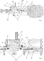
- the reference numeral 1 refers to a placing system of a stopper plug 6 in a perforation 7 in which a land consolidation material is present. This system 1 is used in a jet grouting system.
- the system 1 comprises a conduit 2.
- the conduit 2 extends at least in part outside the perforation 7. In particular, it extends along an imaginary prolongation of said perforation 7.
- the conduit 2 is typically straight.
- the conduit 2 also extends inside the perforation 7.
- the conduit 2 may comprise a connection flange 71 connecting to a front wall 72 from which the perforation 7 extends. Typically this wall extends between the top and the bottom.
- the system 1 further comprises introduction means 3 for introducing the plug 6 into the conduit 2.
- the introduction means 3 may therefore define a loader of the plug 6.
- the system 1 further comprises a pusher member 4 of the plug 6.
- the pusher member 4 is movable along the conduit 2 so as to position the plug 6 in the perforation 7. In fact, by advancing along the conduit 2, the pusher member 4 pushes the plug 6 towards an end of the conduit that opens into said perforation 7.
- the plug 6 is typically inserted into the perforation 7 by interference.
- the plug 6 is deformable; thanks to this deformability it can be compressed transversely to an insertion direction in the perforation 7 and perform a sealing action on the walls of the perforation 7.
- it could be made of rubber or polyurethane resin.
- the plug 6 comprises a first and a second axial end 61, 62.
- the plug 6 also comprises a lateral surface 63 extending between the first and the second end 61, 62.
- the lateral surface 63 narrows as it passes from the first to the second end 61, 62.
- the first axial end 61 is destined to reach more deeply into said perforation 7 with respect to the second axial end 62.
- the plug 6 thus has a converging shape; for example, in the preferred solution the lateral surface 63 is truncoconical.
- the system 1 comprises a perforation rod 5 for carrying out said perforation 7.
- the rod 5 is movable along the conduit 2.
- the conduit 2 is a guide conduit of the perforation rod 5. It is also a guide conduit of the plug 6.
- the pusher member 4 coincides with/is a part of the perforation rod 5. The pusher member 4 is therefore integrated in the rod 5. There are no additional mechanical parts.
- the introduction means 3 for introducing the plug 6 in the conduit 2 comprise a containing tank 31 of the plug 6.
- the tank 31 is located by a side of the conduit 2.
- the tank 31 may comprise an occludable opening 35 that allows loading the plug 6 in the tank 31 from outside the introduction means 3.
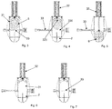
- the introduction means 3 further comprise a thrust actuator 32 suitable to move said plug 6 from a first position in which it is located in the tank 31 to a second position in which it is located in the conduit 2.
- This thrust actuator 32 moves transversely (preferably orthogonally) to the conduit 2.
- the actuator 32 is linear. It is typically fluid-dynamically driven.
- the thrust actuator 32 further comprises a concavity 320 at one end destined to come into contact with and push the plug 6.
- This concavity 320 is destined to at least partially house the plug 6.
- the concavity 320 could be counter-shaped to a portion of the plug 6 with which it comes into contact. This allows to better transfer the thrust on the plug 6, minimising the risk that the plug 6 may slip or position itself in an undesired way.
- the introduction means 3 comprise a dividing wall 33 that is movable between a first configuration (see figures 3 and 7 ) in which it separates said tank 31 from the conduit 2 and a second configuration (see figures 4, 5, 6 ) in which it allows communication between said tank 31 and said conduit 2.
- the dividing wall 33 thus occludes a communication passage 330 between the conduit 2 and the tank 31.
- the dividing wall 33 is a guillotine.
- the plug 6 is allowed to pass from the tank to the conduit 2 (through the above-mentioned communication passage 330).
- the introduction means 3 comprise a moving device 34 suitable to move said dividing wall 33 between the first and the second configuration parallel to the conduit 2.
- the moving device 34 can advantageously be driven fluid-dynamically.
- the moving device 34 is a linear moving device.
- the dividing wall 33 sealingly separates the tank 31 from the conduit 2. This allows preventing the consolidation material injected into the perforation 7 from dirtying the tank 31. This also prevents the consolidation material from dirtying the plug 6 before it is introduced into the conduit 2.
- the conduit 2 comprises a stretch 22 in which the above-mentioned communication passage 330 is obtained.
- This stretch 22 of the conduit 2 is interposed between a first and a second junction 221, 222 connecting it to two further sections of the conduit 2 between which it is interposed.
- the conduit 2 advantageously also comprises a converging section 21 interposed between the above-mentioned communication passage 330 and one end 23 of the conduit 2 destined to engage in the perforation 7.
- the placing system 1 may also comprise radial sealing means between the conduit 2 and the rod 5.
- the radial sealing means comprise, for example:
- This passage 330 advantageously lies between the radial sealing means and an end of the conduit 2 opening into the perforation 7.
- An object of the present invention is also a placing system of a stopper plug 6 in a perforation 7 in which a land consolidation material is present.
- This material is typically fluid.
- This method is advantageously carried out by means of a placing system 1 having one or more of the characteristics described above.
- the method comprises the step of extracting a perforation rod 5 from the perforation 7 while keeping the perforation rod 5 inside a conduit 2 that extends from said perforation 7.
- This conduit 2 is advantageously straight.
- the conduit 2 is coaxial with the perforation 7.
- this step can be accompanied by a leakage of land mixed with the consolidation material from the perforation 7 in the conduit 2. In fact, it is not yet fully consolidated and is therefore movable.
- the consolidation material is typically a mixture comprising water and cement that mixes with the land.
- the conduit 2 also extends inside the perforation 7.
- the method further comprises the step of introducing the plug 6 into the conduit 2, positioning the plug 6 between the perforation rod 5 and an inlet mouth 70 of the perforation 7. This occurs after extracting the rod 5 from the perforation 7.
- the step of introducing the plug 6 in the conduit 2 occurs after retracting the rod 5 so that a zone for introducing the plug 6 into the conduit 2 is interposed between the rod 5 and the perforation 7.
- the step of introducing the plug 6 in the conduit 2 comprises the sub-steps of (advantageously figure 3 shows an initial situation at rest):
- the method comprises the step of pushing the plug 6 along the conduit 2 to fit the plug 6 into the inlet mouth 70 of the perforation 7.
- the step of pushing the plug 6 along the conduit 2 to fit the plug 6 into the inlet mouth 70 of the perforation 7 is carried out by pushing the plug 6 using the perforation rod 5.
- the rod 5 is then moved along the conduit 2 and in particular approached and/or introduced into the inlet mouth 70 of the perforation 7.
- the method may comprise the steps of:
- An object of the present invention is also a method for land consolidation.
- This land consolidation method comprises the step of implementing a placing method of a plug 6 having one or more of the steps described above.
- the land consolidation method Prior to the step of implementing said placing method of the plug 6, the land consolidation method comprises the step of carrying out a perforation 7; advantageously, the step of carrying out the perforation 7 is carried out using the perforation rod 5.
- the method further comprises the step of dispensing consolidation material inside the perforation 7.
- the step of dispensing the consolidation material takes place using at least a dispenser 50 located along the perforation rod 5. In particular this occurs during at least a part of a stroke of the rod 5 which moves from a bottom of said perforation 7 towards the inlet mouth 70 of the perforation 7.
- the dispensed consolidation material advantageously comprises a cementitious material (other components may then be present e.g. a grip accelerator).
- the step of dispensing the consolidation material comprises the step of dispensing a pressurised jet that breaks down the surrounding land.
- the consolidation material will then mix with the surrounding land to form a columnar volume that reinforces the land (especially if several columnar volumes are made connected to each other, each obtained by a corresponding perforation).
- the method comprises the step of rotating said rod 5 around an axis of longitudinal extension of said rod.
- the step of dispensing the consolidation material can be carried out simultaneously by means of a plurality of nozzles, typically orientated along different dispensing directions (possibly they could also be diametrically opposite).
- the consolidation method involves stopping the step of dispensing the consolidation material.
- a first stretch of the perforation 7 has a reduced section, with respect to a second stretch of the perforation in which the land has been broken down by the step of dispensing the consolidation material.
- the first stretch also comprises the inlet mouth 70 of the perforation 7.
- the inlet mouth 70 of the perforation 7 is formed on an artificial wall.
- the perforation 7 could extend from a wall 72 that extends between the top and bottom and defines the front of a tunnel under construction. This front is then coated with a layer of concrete or other material for safety.
- the perforation 7 extends along a straight segment.
- this straight segment has a horizontal component which is greater than the vertical one (meaning that the vertical component could also be zero).
- the inlet mouth 70 is located at a lower height or at the same height as the bottom of the perforation.
- the perforation 7 therefore extends horizontally or upwards (preferably slightly upwards). If necessary, the perforation could also extend downwards (if below a water head).
- the present invention achieves important advantages.
Landscapes
- Engineering & Computer Science (AREA)
- Life Sciences & Earth Sciences (AREA)
- Structural Engineering (AREA)
- Mining & Mineral Resources (AREA)
- General Life Sciences & Earth Sciences (AREA)
- Paleontology (AREA)
- General Engineering & Computer Science (AREA)
- Civil Engineering (AREA)
- Environmental & Geological Engineering (AREA)
- Geology (AREA)
- Fluid Mechanics (AREA)
- Geochemistry & Mineralogy (AREA)
- Physics & Mathematics (AREA)
- Hydrology & Water Resources (AREA)
- Agronomy & Crop Science (AREA)
- Soil Sciences (AREA)
- Consolidation Of Soil By Introduction Of Solidifying Substances Into Soil (AREA)
- Catching Or Destruction (AREA)
- Absorbent Articles And Supports Therefor (AREA)
Priority Applications (1)
| Application Number | Priority Date | Filing Date | Title |
|---|---|---|---|
| EP20206760.9A EP3808903A1 (de) | 2019-05-27 | 2020-04-27 | Platzierungssystem und verfahren für einen stopfen in einer perforation |
Applications Claiming Priority (1)
| Application Number | Priority Date | Filing Date | Title |
|---|---|---|---|
| IT102019000007254A IT201900007254A1 (it) | 2019-05-27 | 2019-05-27 | Sistema e metodo di posa di un tappo di occlusione di una perforazione |
Related Child Applications (2)
| Application Number | Title | Priority Date | Filing Date |
|---|---|---|---|
| EP20206760.9A Division EP3808903A1 (de) | 2019-05-27 | 2020-04-27 | Platzierungssystem und verfahren für einen stopfen in einer perforation |
| EP20206760.9A Division-Into EP3808903A1 (de) | 2019-05-27 | 2020-04-27 | Platzierungssystem und verfahren für einen stopfen in einer perforation |
Publications (2)
| Publication Number | Publication Date |
|---|---|
| EP3744902A2 true EP3744902A2 (de) | 2020-12-02 |
| EP3744902A3 EP3744902A3 (de) | 2021-02-17 |
Family
ID=68234060
Family Applications (2)
| Application Number | Title | Priority Date | Filing Date |
|---|---|---|---|
| EP20206760.9A Withdrawn EP3808903A1 (de) | 2019-05-27 | 2020-04-27 | Platzierungssystem und verfahren für einen stopfen in einer perforation |
| EP20171550.5A Withdrawn EP3744902A3 (de) | 2019-05-27 | 2020-04-27 | Verfahren zur verfestigung eines untergrunds |
Family Applications Before (1)
| Application Number | Title | Priority Date | Filing Date |
|---|---|---|---|
| EP20206760.9A Withdrawn EP3808903A1 (de) | 2019-05-27 | 2020-04-27 | Platzierungssystem und verfahren für einen stopfen in einer perforation |
Country Status (3)
| Country | Link |
|---|---|
| EP (2) | EP3808903A1 (de) |
| DE (1) | DE202020005620U1 (de) |
| IT (1) | IT201900007254A1 (de) |
Family Cites Families (12)
| Publication number | Priority date | Publication date | Assignee | Title |
|---|---|---|---|---|
| US1764948A (en) * | 1929-06-14 | 1930-06-17 | Frankignoul Pieux Armes | Method for driving lining tubes for molding concrete piles in the ground |
| DE1634565B2 (de) * | 1964-05-22 | 1973-02-08 | Schdruzeni kamenouhelnych dolu, Kladno (Tschechoslowakei) | Injektionsgeraet fuer das einpressen von zwei miteinander reagierenden fluessigkeiten zum abdichten des baugrundes |
| JPS634115A (ja) * | 1986-06-24 | 1988-01-09 | Kyokado Eng Co Ltd | 地盤注入工法 |
| DE3718631A1 (de) * | 1987-06-03 | 1988-12-22 | Gkn Keller Gmbh | Kombiniertes injektionsverfahren sowie vorrichtung zur herstellung eines hochverfestigten bodenvolumens bei gleichzeitiger stabilisierung des angrenzenden bodens |
| JP2001164589A (ja) * | 1999-12-08 | 2001-06-19 | Shimizu Corp | 高圧気体貯蔵施設の構築方法 |
| US9169611B2 (en) * | 2000-06-15 | 2015-10-27 | Geopier Foundation Company, Inc. | Method and apparatus for building support piers from one or more successive lifts formed in a soil matrix |
| JP3626972B1 (ja) * | 2003-10-02 | 2005-03-09 | 栄興産業株式会社 | 噴射攪拌工法および噴射攪拌装置 |
| KR100776304B1 (ko) * | 2006-05-25 | 2007-11-16 | 정진교 | 그라우팅 구멍이 다수개 일정한 간격을 두고 설치된 강관의내부에 다수개의 패커를 설치한 직천공 동시 주입장치 및이를 이용한 직천공그라우팅시공방법 |
| DE102007023736B4 (de) * | 2007-05-22 | 2011-01-20 | Bauer Spezialtiefbau Gmbh | Schnellabbindende HDI |
| KR101082528B1 (ko) * | 2009-12-22 | 2011-11-10 | 김성희 | 지수패커 및 이를 채용한 강연선 홀딩장치 |
| KR101545254B1 (ko) * | 2014-08-28 | 2015-08-20 | 최정옥 | 중압혼합분사 주입장치 및 이를 이용한 주상형 구조체 시공방법 |
| KR101552466B1 (ko) * | 2014-11-26 | 2015-09-10 | 윤택규 | 자중식 지반밀착형 인발저항콘과 이를 이용한 지반보강공법 및 지반보강장치 |
-
2019
- 2019-05-27 IT IT102019000007254A patent/IT201900007254A1/it unknown
-
2020
- 2020-04-27 EP EP20206760.9A patent/EP3808903A1/de not_active Withdrawn
- 2020-04-27 DE DE202020005620.0U patent/DE202020005620U1/de active Active
- 2020-04-27 EP EP20171550.5A patent/EP3744902A3/de not_active Withdrawn
Also Published As
| Publication number | Publication date |
|---|---|
| DE202020005620U1 (de) | 2021-11-02 |
| EP3808903A1 (de) | 2021-04-21 |
| EP3744902A3 (de) | 2021-02-17 |
| IT201900007254A1 (it) | 2020-11-27 |
Similar Documents
| Publication | Publication Date | Title |
|---|---|---|
| CA2104844C (en) | Long hole chemical grout injector system | |
| US20070264088A1 (en) | Method for Embedding Rock Anchors | |
| EP3129744B1 (de) | Verfahren und anordnung zur abgabe einer sprengladung in ein bohrloch | |
| EP3744902A2 (de) | Verfahren zur verfestigung eines untergrunds | |
| EP1745840A1 (de) | Vorrichtung und Verfahren zum Mischen eines flüssigen und eines fliessfähigen pulverförmigen Materials zur Herstellung einer Suspension | |
| JP5824588B1 (ja) | 真空グラウト注入工法 | |
| CN101583556A (zh) | 填料阀单元 | |
| CN116391072A (zh) | 用于树脂注射的设备、采矿机器和方法 | |
| KR101721494B1 (ko) | 정압 동시주입 다단가압식 그라우팅 장치 | |
| CA1048927A (en) | Plug for injection | |
| SK283910B6 (sk) | Spôsob vytvárania podzemných tesniacich stien | |
| JP3961510B2 (ja) | 地盤注入工法 | |
| KR101550158B1 (ko) | 피씨 콘크리트 블록을 이용한 수직구 가시설 설치방법 및 장치 | |
| KR101859905B1 (ko) | 지반 굴착 및 보강 시공 방법 및 그 장치 | |
| US4497578A (en) | Machine for mixing and injecting water and grout into a roof bolt hole | |
| US1478865A (en) | Machine for injecting plastic materials | |
| CN108590621B (zh) | 煤矿井下水力压裂远程连续泵后高压加砂系统及其方法 | |
| CN210508412U (zh) | 一种自动控量的套筒灌浆缺陷修复装置 | |
| KR20250019243A (ko) | 압력감지 상승용 c.g.s 그라우팅 주입방법 및 c.g.s 그라우팅 주입장치 | |
| KR102357301B1 (ko) | 자동화 그라우팅 시스템 | |
| EP3733974B1 (de) | Verfahren zur bodenkonsolidierung und/oder impermeabilisierung | |
| US3484082A (en) | Apparatus for automatically injecting mixtures into the ground | |
| KR20180023648A (ko) | 액상의 내용물 충진용 주입기 노즐 조립체 | |
| KR102420953B1 (ko) | 동시주입 강관그라우팅 장치를 이용한 그라우팅 공법 | |
| KR101778974B1 (ko) | 모르타르 분사장치 |
Legal Events
| Date | Code | Title | Description |
|---|---|---|---|
| PUAI | Public reference made under article 153(3) epc to a published international application that has entered the european phase |
Free format text: ORIGINAL CODE: 0009012 |
|
| STAA | Information on the status of an ep patent application or granted ep patent |
Free format text: STATUS: THE APPLICATION HAS BEEN PUBLISHED |
|
| AK | Designated contracting states |
Kind code of ref document: A2 Designated state(s): AL AT BE BG CH CY CZ DE DK EE ES FI FR GB GR HR HU IE IS IT LI LT LU LV MC MK MT NL NO PL PT RO RS SE SI SK SM TR |
|
| AX | Request for extension of the european patent |
Extension state: BA ME |
|
| PUAL | Search report despatched |
Free format text: ORIGINAL CODE: 0009013 |
|
| AK | Designated contracting states |
Kind code of ref document: A3 Designated state(s): AL AT BE BG CH CY CZ DE DK EE ES FI FR GB GR HR HU IE IS IT LI LT LU LV MC MK MT NL NO PL PT RO RS SE SI SK SM TR |
|
| AX | Request for extension of the european patent |
Extension state: BA ME |
|
| RIC1 | Information provided on ipc code assigned before grant |
Ipc: C09K 17/10 20060101ALI20210111BHEP Ipc: E02D 5/46 20060101ALI20210111BHEP Ipc: E02D 5/66 20060101ALI20210111BHEP Ipc: C09K 17/12 20060101ALI20210111BHEP Ipc: E02D 31/10 20060101AFI20210111BHEP Ipc: E02D 37/00 20060101ALI20210111BHEP Ipc: E02D 3/12 20060101ALI20210111BHEP |
|
| STAA | Information on the status of an ep patent application or granted ep patent |
Free format text: STATUS: THE APPLICATION IS DEEMED TO BE WITHDRAWN |
|
| 18D | Application deemed to be withdrawn |
Effective date: 20210818 |