EP3129744B1 - Verfahren und anordnung zur abgabe einer sprengladung in ein bohrloch - Google Patents
Verfahren und anordnung zur abgabe einer sprengladung in ein bohrloch Download PDFInfo
- Publication number
- EP3129744B1 EP3129744B1 EP15776161.0A EP15776161A EP3129744B1 EP 3129744 B1 EP3129744 B1 EP 3129744B1 EP 15776161 A EP15776161 A EP 15776161A EP 3129744 B1 EP3129744 B1 EP 3129744B1
- Authority
- EP
- European Patent Office
- Prior art keywords
- plug
- hose
- bore hole
- conduit
- explosive
- Prior art date
- Legal status (The legal status is an assumption and is not a legal conclusion. Google has not performed a legal analysis and makes no representation as to the accuracy of the status listed.)
- Active
Links
Images
Classifications
-
- F—MECHANICAL ENGINEERING; LIGHTING; HEATING; WEAPONS; BLASTING
- F42—AMMUNITION; BLASTING
- F42D—BLASTING
- F42D1/00—Blasting methods or apparatus, e.g. loading or tamping
- F42D1/08—Tamping methods; Methods for loading boreholes with explosives; Apparatus therefor
- F42D1/10—Feeding explosives in granular or slurry form; Feeding explosives by pneumatic or hydraulic pressure
-
- F—MECHANICAL ENGINEERING; LIGHTING; HEATING; WEAPONS; BLASTING
- F42—AMMUNITION; BLASTING
- F42D—BLASTING
- F42D1/00—Blasting methods or apparatus, e.g. loading or tamping
- F42D1/08—Tamping methods; Methods for loading boreholes with explosives; Apparatus therefor
- F42D1/18—Plugs for boreholes
Definitions
- the invention relates to a method and arrangement for providing explosive charging into a mining or tunnelling hole, or a bore hole hereinafter.
- ANFO ammonium nitrate-fuel oil explosive
- the explosive end product can be achieved by mixing the dry powder ammonium nitrate with additive material, such as water, fuel oil or special chemicals (later additives). The mixing additionally makes ANFO sticky so to stay better in vertical up holes.
- additive material such as water, fuel oil or special chemicals (later additives).
- Another purpose of increasing the additive is reducing dusting of dry ANFO.
- this additive is dosed directly to an ANFO tank or right after the tank if special dosing devices are used.
- this method usually results blockages in the ANFO tank and ANFO hoses because of softened half-melted ANFO prill structure. Blockages slow down charging work and due that whole mining cycle.
- emulsion charging emulsion matrix which is not explosive material as such, but it is sensitized to emulsion explosive by using dedicated gassing solution which is mixed to matrix.
- gassing solution is dosed and mixed in an early stage in process unit and then pumped through water lubricated 20-60 m long charging hose, for example, to the bore hole.
- problems relate also to ensuring that the materials used for explosive charging would be introduced in a desired depth in the hole and so that they would not flow to an undesired portion of the hole.
- the hole may be e.g. an upper hand hole, where the hole is drilled in upward direction, whereupon it must be ensured that the charging materials do not flow away from the hole.
- Other example is the case of a lower hand hole, where the hole is charged from above and where the charging materials should not enter into the bottom of the hole, or where there is a need to leave an empty portion into the hole and thus ensure that the charging material does not flow into the bottom or into the empty portion of the hole.
- CA2236002A1 discloses a device for plugging an explosives blasthole, the device having an inner member in the form of a conduit having a valve and being adapted for the passage of fluid bulk explosives and an outer member adapted to engage the walls of the blasthole.
- the outer member may be made of deformable material or be inflatable.
- the inner and outer members may be detachable.
- US5524523 discloses a system for loading flowable explosives into a borehole and inserting a plug of a flowable stemming material into the borehole.
- the plug is made feeding the flowable stemming material or constituents thereof along one of the conduits into the borehole.
- An object of the invention is to alleviate and eliminate the problems relating to the known prior art.
- the object of the invention is to provide an arrangement and method, as well as a charging hose for ensuring that the materials used for explosive charging would be introduced and keep in a desired depth in the hole and so that they would not flow to an undesired portion of the hole.
- the object is to perform the task easily and fast as well as in a reliable manner.
- An additional object of the invention is for enabling to provide explosive charging into a bore hole so that the blockages of the explosive material in the hose or danger of explosion caused by the sensitized emulsion explosive can be overcome and avoided.
- the invention relates to the arrangement providing explosive charging and a plug into a bore hole according, charging hose and mixer combination, and method for providing the explosive charging and plug into the bore hole according to the independent claims.
- One arrangement and charging hose for providing explosive charging and a plug into a bore hole, such as mining or tunnelling hole comprises at least one first conduit advantageously arranged into the hose.
- the conduit as such is formed by said hose.
- the conduit is configured to be introduced into the bore hole.
- the arrangement comprises also at least one plug, which is configured to be introduced into said bore hole by the help of said hose.
- the plug has a diameter, the size of which is configured to be manipulated after or during introducing into said bore hole at a certain depth so that after said introducing the diameter of the plug is larger than before said introducing and so that the surface of the plug after manipulation essentially make a physical contact with the bore hole surface.
- the plug is advantageously introduced into the hole in a releasable manner so that after or during the manipulation of the plug diameter size the plug is be released from the hose so that it stays in the bore hole essentially at said certain depth.
- the plug either expands so that it sticks into the hole, and/or it has material with friction coefficient so that it will be stuck especially after size manipulation into the hole surface.
- the plug advantageously comprises a (closed) volume, which can be manipulated so that the outer volume and thereby said plug diameter size increases. Therefore the plug makes a physical contact with the bore hole surface and forms a mechanical blockage into the hole.
- the plug comprises according to an example inner and outer volumes, whereupon the diameter or outer volume of the plug can be manipulated for example by feeding a filling agent into the inner volume of the plug.
- the filling agent such as pressurized air, is advantageously fed into the plug via at least one conduit of the hose.
- the medium filled plug advantageously stays filled without any enormous leakage after releasing.
- the plug may be coupled with the hose by a breakaway-type quick release coupling, such as a bayonet coupling, but also other types of coupling means can be used, such as a tie around the plug, where the tie is configured to be broken when the plug is filled.
- the coupling is advantageously configured to release the plug from the hose, when the physical contact is made between the plug and the bore hole surface, and/or when the hose is pulled away from the bore hole.
- the plug may comprise compressible material or structure.
- the plug may be a shuttlecock type bore hole plug or the like, whereupon the plug may be compressed by applying an external force before and during the introduction of the plug into the bore hole.
- the plug expands and sticks into the surface of the bore hole and form the blockage.
- the external force may be applied by introducing the plug into the bore hole inside a tube, sock, sleeve or the like, where the tube or the like compresses the plug during introduction.
- the plug can be removed or released from the tube e.g. by pushing it by a medium, advantageously e.g. by pressurized air, which is fed via at least one conduit.
- a medium advantageously e.g. by pressurized air, which is fed via at least one conduit.
- the plug may be a shuttlecock type plug or functionally similar plug.
- the tube used for introducing said plug is advantageously a portion of at least one conduit.
- the shuttlecock can be inserted at the opening of conduit or hose, whereupon it can be "shot” by pressurised air pulse fed via said conduit or hose, when the end of the hose is at the desired depth and before feeding the explosive material via said hose or conduit.
- the plug may be provided by introducing at least one, preferably two or more chemical components so that it or they will expand after or during releasing from the hose or outlet of the conduit(s).
- the chemicals may be for example polyol component and polymeric component, when a hydrophobic polyurethane foam is formed when mixed.
- This kind of foam is tough, rigid and resistant, as well as its expansion can be controlled, whereupon it is suitable as a plug.
- a suitable plug which stays in the bore hole essentially at said certain depth can be formed.
- the plug can be introduced into the bore hole essentially by the same one in-out movement of the hose as used for introducing at least the component(s) of an explosive material.
- the plug is provided (brought, released and/or formed) into or at the desired depth in the bore hole, whereupon the charging material(s) can be fed directly after the plug is inserted or formed into the hole.
- the arrangement and charging hose comprises a charging conduit and an additional conduit both comprising inlets and outlets, respectively.
- the charging conduit is configured for introducing explosive base material, such as e.g. ANFO or emulsion based material to the outlet of said charging conduit.
- the additional conduit is configured for introducing additive material, such as e.g. water, fuel oil or special chemicals to the outlet of said additional conduit.
- the additive materials are used e.g. to make ANFO sticky so to stay in vertical up holes, as well as reducing dusting of dry ANFO.
- the additives can also be used for gassing solution used for sensitizing an emulsion explosive, for example.
- Said charging conduit and additional conduit are arranged into a common hose, which can then be introduced into said bore hole so that said explosive base material and additive material are provided via said own conduits separately from each other and without any contact with each other.
- the explosive base material and additive material are configured to be mixed in the arrangement with each other after said outlets of said conduits in order to provide said explosive charging into the bore hole.
- Said common hose forms said charging hose.
- the additive can be brought separately to the outlet of the charging conduit and dose it directly.
- the mixing of the additive into the ANFO flow can thus be done using at the end portion (outlet) of the charging conduit by using a suitable ejector and nozzle, for example.
- This embodiment significantly decreases the blockages and due that down times in charging and whole mining cycle.
- a mixer device may be arranged after gassing solution junction to properly mix the gassing solution to the base matrix.
- the mixing of the explosive base material and additive material is advantageously arranged before the outlet of the common hose, like e.g. 1 or few meters before the outlet of the common hose so to ensure a better mixing during the end portion of the common hose.
- the arrangement and the charging hose may comprise additionally a third conduit for further additional media, such as for pressurized air, for example.
- the third and additional conduits are advantageously arranged symmetrically into the opposite sides of the common hose in order to make the common hose more durable and stable, even if this is not compulsory.
- the third and additional conduits are arranged at the rim portion of the common hose and the centre portion of the common hose is used as a charging conduit.
- the outlets at least of the charging and additional conduits are arranged before the outlet of the common hose.
- the outlet (e.g. sub-outlet) of the third conduit can be arranged before the outlet of the common hose, but according to an embodiment it can also be arranged at the outlet area of the common hose.
- the common hose may be configured to introduce a bore hole plugging into the bore hole. Very often downward bore holes through to a next level must be plugged before charging. Also in upward emulsion charging hole must be plugged right after charging. Otherwise charged emulsion can come down initially after charging.
- the integrated additional or third conduits of the common hose (or charging hose) are configured to be used as a channel for introducing filling agent or other manipulating agent to dedicated bore hole plug devices, like blast air balls, so that they are able to plug the bore holes.
- the arrangement may be automatized at least partially.
- the hose with the plug can be introduced into the bore hole, after which the plug is released at the first predetermined depth, after which the explosive material is provided starting at the second predetermined depth.
- the plug may be released before feeding the explosive material and/or vice versa.
- the first plug may be released first, after which the first portion of the explosive material can be fed, next the second plug may be released at the second depth and so on.
- the concentration of the mixed explosive provided into the bore hole can be changed in the function of the depth so that in the first portion of the hole the provided mixed explosive has a first concentration and in the second portion of the hole the provided mixed explosive has a second concentration differing from the first one.
- the present invention offers advantages over the known prior art, such as that a great number of possible blockages can be avoided, since the ANFO is not mixed with additive until the end portion of the charging hose.
- gassing reaction starts only at the end portion of the charging hose, which removes the danger of explosion caused by the sensitized emulsion explosive in the charging hose.
- the common hose comprising the conduits, both the charging conduit and the additional conduit, and optionally also the third conduit, can be used with one hose manipulator and/or one hose feeder, for example, whereupon the operation of the whole charging project is very easy and fast, as well as additionally also safe maneuver.
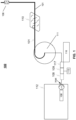
- FIG 1 illustrates a principle of an exemplary arrangement 100 and Figures 2A-2B and Figures 3A-3B examples of a charging hose 101 for providing explosive charging and a plug 114 into a bore hole 102.
- the arrangement 100 and charging hose 101 comprises at least one first conduit 103 advantageously arranged into the hose 101, as well as at least one plug 114, which is be introduced into the bore hole 102 by the help of said hose.
- the plug 114 has a diameter, the size of which is configured to be manipulated after or during introducing the plug into the bore hole 102 at a certain depth so that after said introducing the diameter of the plug is larger than before said introducing and so that the surface of the plug after manipulation essentially make a physical contact with the bore hole surface.
- the plug is advantageously introduced into the hole in a releasable manner, which can be implemented e.g. by coupling the plug, such as a ball, with the hose 101 by a breakaway type quick release coupling 115, such as a bayonet coupling.
- the arrangement 100 and charging hose 101 comprises also a charging conduit 103 and an additional conduit 104 both comprising inlets and outlets, respectively.
- the charging conduit 103 is configured for introducing explosive base material to the outlet of said charging conduit.
- the additional conduit 104 is configured for introducing additive material.
- the charging conduit 103 and additional conduit 104 are advantageously arranged into a common hose 101 (charging hose).
- the charging hose 101 can then be introduced into the bore hole 102 so that the explosive base material and additive material are provided via said own conduits 103, 104 separately from each other and without any contact with each other.
- the explosive base material and additive material are mixed by a mixer device 106 with each other after said outlets of said conduits 103, 104 in order to provide said explosive charging 107 into the bore hole.
- the charging hose 101 may also comprise additionally a third conduit 105 for further additional media, such as for pressurized air, for example.
- the third 105 and additional conduits 104 are advantageously arranged symmetrically into the opposite sides of the common hose 101.
- the third 105 and additional conduits 104 are arranged at the rim portion of the common hose 101 and the centre portion of the common hose is used as a charging conduit 104.
- the outlets at least of the charging 103 and additional conduits 104 are advantageously arranged before the outlet 101a of the common hose 101.
- the outlet of the third conduit 105 can be arranged before the outlet 101a of the common hose, but it can also be arranged at the outlet area 101a of the common hose 101.
- the arrangement comprises a mixer 106 arranged in connection with the hose.
- the mixer 106 can be arranged at the portion of the outlets of the charging and additional conduits 103, 104, especially when the mixer 106 is used to mix the explosive base material and additive material, like ANFO and water, fuel oil or special chemicals.
- the mixer 106 is located at the end of the common hose, which is especially advantageous when the mixer (or, in an example outside of the scope of the current invention, a suitable ejector and nozzle) is used for gassing emulsion.
- the arrangement may also comprise a feeding means (or feeder or pump) 108 for feeding said explosive base material and a dosing means (or dispenser) 109 configured for dosing said additive material in a certain relation with the fed explosive base material. It is to be noted that these means 108, 109 may also locate elsewhere in the arrangement than described in Figures, as for example in a tank 112.
- the arrangement may also comprise a hose pusher 110 for pushing the hose with the plug into the mining hole 102 in a controllable manner, so for example into a desired depth before releasing the plug.
- the hose pusher 110, as well as valves and feeding means or pumps are advantageously coupled with a control unit 116, which is configured to control the feeding of the charging material(s), feeding of the hose as well as manipulation and releasing of the plug.
- the arrangement may also comprise a reel 111 for carrying the hose, where the inlet of the charging conduit is configured to be introduced into a tank 112 of explosive base material and the inlet of the additional conduit is configured to be introduced into a tank 113 of additive material.
- the inlet of the optional third conduit 105 is configured to be introduced into an air compressor, for example (not shown).
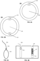
- Figure 3 illustrates a principle of an exemplary arrangement 100 for providing a bore hole plug 114 into the bore hole 102.
- the common hose 101 (or charging hose) is configured to introduce the bore hole plugging 114 into the bore hole so that the integrated additional 104 or third conduits 105 of the common hose 101 (or charging hose) are configured to be used as a channel for introducing filling agent or other manipulating agent to dedicated bore hole plug devices 114.
- the bore hole plug may be e.g. a blast air ball 114, which is configured to expand for example and thereby to plug the bore hole 102.
- plugs discussed in this description such as plug made by mixing chemical components and otherwise suitable for using as the plug in the meaning described here are possible.
- the hose 101 is advantageously configured to bring also the bore hole plug 114 with itself to the mining hole 102.
- the outer volume of the bore hole plug is advantageously configured to be manipulated by feeding filling agent, like air or water or the like into the bore hole plug.
- the arrangement advantageously comprises a remote controllable valve 117 coupled between the additional or third conduit 104, 105 (or the hose may comprise a second additional conduit for filling agent of filling said plug) and the bore hole plug 114 located advantageously at the end portion of the hose 101.
- the outer volume of the bore hole plug 114 is small, as can be seen in Figure 3A , whereupon it can be fed into the bore hole 102.
- the bore hole plug 114 may be manipulated so to change its outer volume e.g. by controlling the flow of said additional or third conduit 104, 105 for said bore hole plug via the remote controllable valve 117, as can be seen in Figure 3B .
- the change of the outer volume of said bore hole plug 114 may be configured to happen e.g. by feeding filling agent into said bore hole plug.
- the invention has been explained above with reference to the aforementioned embodiments, and several advantages of the invention have been demonstrated. It is clear that the invention is not only restricted to these embodiments but comprises all possible embodiments within the scope of the following patent claims.
- the anfo or charging emulsion matrix are mentioned as the explosive base material, it is to be noted that also other suitable explosive material can also be used.
- more than one plug can be introduced into the hole by same movement of the hose.
- the first plug may be coupled with the first conduit, and the second plug with the second conduit and advantageously so that they can be manipulated and released independently of each other.
Landscapes
- Life Sciences & Earth Sciences (AREA)
- General Life Sciences & Earth Sciences (AREA)
- Engineering & Computer Science (AREA)
- General Engineering & Computer Science (AREA)
- Drilling And Exploitation, And Mining Machines And Methods (AREA)
- Accessories For Mixers (AREA)
- Geophysics And Detection Of Objects (AREA)
Claims (14)
- Anordnung (100) zum Bereitstellen einer Sprengladung (107) und eines Stopfens (114) in einem Bohrloch (102), wie etwa einem Bergbau- oder Tunnelbauloch, umfassend- einen Ladeschlauch (101), der mindestens eine erste Leitung (103) umfasst, die in das Bohrloch (102) einzuführen ist, und zum Einführen mindestens eines explosiven Basismaterials zu einem Auslass der ersten Leitung und dadurch in das Bohrloch, und- mindestens einen Stopfen (114), der konfiguriert ist, um mit Hilfe des Schlauchs (101) in das Bohrloch eingeführt zu werden,- wobei der Stopfen (114) einen Durchmesser hat, dessen Größe konfiguriert ist, um nach oder während des Einführens in das Bohrloch in einer bestimmten Tiefe manipuliert zu werden, so dass nach dem Einführen der Durchmesser des Stopfens größer ist als vor dem Einführen, und so dass die Oberfläche des Stopfens nach dem Manipulieren der Größe des Durchmessers im Wesentlichen einen physischen Kontakt mit der Oberfläche des Bohrlochs (102) herstellt,- wobei der Stopfen (114) durch den Schlauch (101) auf lösbare Weise eingeführt wird, so dass nach oder während des Manipulierens der Stopfendurchmessergröße der Stopfen so konfiguriert ist, dass er von dem Schlauch (101) gelöst wird und im Wesentlichen in der bestimmten Tiefe in dem Bohrloch (102) verbleibt, und- wobei der Stopfen (114) so konfiguriert ist, dass er in das Bohrloch durch die gleiche Einwärts-Auswärts-Bewegung des Schlauchs (101) eingeführt wird, die zum Einführen von mindestens dem explosiven Grundmaterial verwendet wird,dadurch gekennzeichnet, dass der Schlauch (101) eine zweite zusätzliche Leitung (104) zum Einführen von Zusatzmaterial zu einem Auslass der zusätzlichen Leitung umfasst, und dadurch, dass die Anordnung ferner einen Mischer (106) in Verbindung mit dem Schlauch zum Mischen eines explosiven Grundmaterials und eines Zusatzmaterials umfasst, wobei die erste Leitung eine erste Ladeleitung (103) ist, die erste Ladeleitung (103) und die zweite zusätzliche Leitung (104) in dem gemeinsamen Schlauch (101) angeordnet sind, der durch den Ladeschlauch (101) gebildet wird, so dass das explosive Basismaterial und das Zusatzmaterial getrennt voneinander über die Leitungen (103, 104) zugeführt werden, und wobei das Basismaterial für Sprengstoff und das Zusatzmaterial konfiguriert sind, um nach Auslässen der Leitungen (103, 104) miteinander vermischt zu werden, um die Sprengladung in das Bohrloch (102) einzubringen, wobei die Auslässe der Leitungen vor einem Auslass des gemeinsamen Schlauchs angeordnet sind und der Mischer am Auslass des gemeinsamen Schlauchs angeordnet ist, so dass ein Abschnitt des gemeinsamen Schlauchs nach den Auslässen der Leitungen nur eine Schlauchstruktur bildet.
- Anordnung nach dem vorhergehenden Anspruch, wobei der Stopfen (114) ein Volumen umfasst, das konfiguriert ist, um manipuliert zu werden, so dass das äußere Volumen und dadurch die Durchmessergröße des Stopfens so konfiguriert wird, dass sie vergrößert wird und wieder den physischen Kontakt mit der Bohrlochoberfläche herstellt.
- Anordnung nach einem der vorhergehenden Ansprüche, wobei der Stopfen (114) ein inneres und ein äußeres Volumen umfasst, woraufhin der Durchmesser oder das äußere Volumen des Stopfens so konfiguriert ist, dass es manipuliert wird, indem ein Füllmittel in das innere Volumen des Stopfens eingeführt wird, wobei das Füllmittel vorteilhafterweise über mindestens eine Leitung (103, 104, 105) des Schlauchs (101) in den Stopfen eingebracht wird.
- Anordnung nach einem der vorhergehenden Ansprüche, wobei die Anordnung ein steuerbares Ventil (117) umfasst, das mit mindestens einer Leitung des Schlauchs, insbesondere mit der zweiten zusätzlichen (104) oder einer dritten (105) Leitung und dem Stopfen (114) gekoppelt ist, woraufhin die Anordnung so konfiguriert ist, dass sie das Füllmittel in den Stopfen (114) liefert, um sein Volumen oder seinen Außendurchmesser zu ändern, indem der Fluss der Leitung in den Stopfen gesteuert wird.
- Anordnung nach einem der vorhergehenden Ansprüche, wobei der Stopfen (114) mit dem Schlauch (101) durch eine Schnelllösekupplung (115) vom Abreißtyp, wie etwa eine Bajonettkupplung, gekoppelt ist, die so konfiguriert ist, dass es den Stopfen (114) von dem Schlauch (101) löst, wenn der physische Kontakt zwischen dem Stopfen (114) und der Oberfläche des Bohrlochs (102) hergestellt wird, und/oder wenn der Schlauch vom Bohrloch weggezogen wird.
- Anordnung nach den vorhergehenden Ansprüchen, wobei der Stopfen (114) ein komprimierbares Material oder eine komprimierbare Struktur umfasst, woraufhin der Stopfen so konfiguriert ist, dass er durch Aufbringen der äußeren Kraft vor dem Einführen in das Bohrloch komprimiert wird, und woraufhin die externe Kraft so konfiguriert ist, dass sie entfernt wird, nachdem der Stopfen in das Bohrloch in der bestimmten Tiefe eingeführt wurde.
- Anordnung nach Anspruch 6, wobei die äußere Kraft aufgebracht wird, indem der Stopfen in das Bohrloch innerhalb eines Rohrs eingeführt wird, wobei das Rohr den Stopfen während des Einführens zusammendrückt, und wobei der Stopfen so konfiguriert ist, dass er von dem Rohr gelöst wird, indem er durch das über mindestens eine Leitung (103, 104, 105) zugeführte Medium geschoben wird, und dadurch die Ausdehnung des Stopfendurchmessers nach dem Entfernen oder Lösen aus dem Rohr ermöglicht wird.
- Anordnung nach Anspruch 6 oder 7, wobei der Stopfen ein Federball-Stopfen ist und/oder wobei das zum Einführen des Stopfens verwendete Rohr ein Abschnitt von mindestens einer Leitung ist.
- Anordnung nach einem der Ansprüche 1 oder 2, wobei die Anordnung so konfiguriert ist, dass sie den Stopfen bereitstellt, indem sie mindestens eine, vorzugsweise zwei oder mehr chemische Komponenten bereitstellt, so dass er oder sie sich nach oder während des Lösens aus dem Schlauch oder Auslass der Leitungen ausdehnen und dadurch bewirken, dass der Stopfen im Wesentlichen in der bestimmten Tiefe in dem Bohrloch verbleibt.
- Anordnung nach einem der vorhergehenden Ansprüche, wobei die Anordnung eine Zuführeinrichtung (108) zum Zuführen der mindestens einen Komponente des explosiven Materials und eine Dosiereinrichtung (109) umfasst, die zum Dosieren eines Zusatzmaterials in einem bestimmten Verhältnis zu dem zugeführten Sprengstoffbasismaterial konfiguriert ist.
- Anordnung nach einem der vorhergehenden Ansprüche, wobei die Anordnung dazu konfiguriert ist, den Schlauch mit dem Stopfen in das Bohrloch einzuführen, den Stopfen in einer ersten vorbestimmten Tiefe freizugeben und das explosive Material beginnend in einer zweiten vorbestimmten Tiefe bereitzustellen.
- Anordnung nach einem der vorhergehenden Ansprüche, wobei die Anordnung so konfiguriert ist, dass sie die Konzentration des in das Bohrloch bereitgestellten gemischten Sprengstoffs ändert, so dass im ersten Abschnitt des Lochs der bereitgestellte Mischsprengstoff eine erste Konzentration aufweist und in dem zweiten Abschnitt des Lochs der bereitgestellte gemischte Sprengstoff eine zweite Konzentration aufweist, die sich von der ersten unterscheidet.
- Ladeschlauch- und Mischerkombination (101, 106), die in der Anordnung (100) nach einem der vorhergehenden Ansprüche verwendet werden soll, umfassend mindestens- der Ladeschlauch (101),- die erste Ladeleitung (103) zum Einführen des explosiven Basismaterials zum Auslass der ersten Leitung,- die zweite zusätzliche Leitung (104) zum Einführen des Additivmaterials in den Auslass der zusätzlichen Leitung, und- den Mischer (106) in Verbindung mit dem Schlauch zum Mischen des explosiven Basismaterials und des Zusatzmaterials,- wobei die erste Ladeleitung (103) und die zweite zusätzliche Leitung (104) in dem gemeinsamen Schlauch (101) angeordnet sind, der konfiguriert ist, um in das Bohrloch (102) eingeführt zu werden, so dass die mindestens eine Komponente des explosiven Materials und das Zusatzmaterial getrennt voneinander über die Leitungen (103, 104) bereitgestellt werden,- wobei das Basismaterial für den Sprengstoff und das Zusatzmaterial konfiguriert sind, um nach den Auslässen der Leitungen (103, 104) miteinander vermischt zu werden, um die Sprengladung (107) in das Bohrloch (102) einzubringen, wobei die Auslässe der Leitungen vor dem Auslass des gemeinsamen Schlauchs und der Mischer am Auslass des gemeinsamen Schlauchs angeordnet sind, so dass der Abschnitt des gemeinsamen Schlauchs nach den Auslässen der Leitungen nur eine Schlauchstruktur bildet.
- Verfahren zum Bereitstellen einer Sprengstoffladung (107) und des Stopfens (114) in dem Bohrloch (102), wie beispielsweise dem Bergbau- oder Tunnelbohrloch, mittels der Anordnung (100) nach einem der Ansprüche 1 bis 12, umfassend folgende Schritte:- Einführen des Schlauchs (101), der mindestens die erste Ladeleitung (103), die zweite zusätzliche Leitung (104) und den Mischer (106) in Verbindung mit dem Schlauch zum Mischen des Sprengstoffgrundmaterials und des Zusatzmaterials umfasst, in die Bohrloch,- Anordnen der ersten Leitung und der zusätzlichen Leitung in dem gemeinsamen Schlauch (101),- lösbares Einführen mindestens eines Stopfens (114) mittels des Schlauchs, so dass der Stopfen von dem Schlauch gelöst wird, um im Wesentlichen in der bestimmten Tiefe in dem Bohrloch zu bleiben,- Manipulieren der Größe des Durchmessers des Stopfens nach oder während des Einführens in das Bohrloch in der bestimmten Tiefe, so dass nach oder während des Einführens der Durchmesser des Stopfens größer ist als vor dem Einführen, und damit die Oberfläche des Stopfens nach dem Manipulieren der Durchmessergröße im Wesentlichen den physischen Kontakt mit der Bohrlochoberfläche herstellt,- Einführen des Basismaterials für Sprengstoff über die erste Leitung zu einem Auslass der ersten Leitung und über die zusätzliche Leitung des Additivmaterials zu einem Auslass der zusätzlichen Leitung getrennt voneinander, und- Mischen des explosiven Grundmaterials und des Zusatzmaterials miteinander nach Auslässen der Leitungen (103, 104) am Abschnitt des gemeinsamen Schlauchs und dann im Mischer am Auslass des gemeinsamen Schlauchs, um die Sprengladung (107) in das Bohrloch (102) einzubringen,- wobei das Einführen des Stopfens in das Bohrloch durch die gleiche Einwärts-Auswärts-Bewegung des Schlauchs (101) durchgeführt wird, wie sie zum Einführen der Sprengbasis- und Zusatzmaterialien verwendet wird.
Applications Claiming Priority (2)
| Application Number | Priority Date | Filing Date | Title |
|---|---|---|---|
| FI20145341 | 2014-04-10 | ||
| PCT/FI2015/050249 WO2015155418A1 (en) | 2014-04-10 | 2015-04-10 | Method and arrangement for providing explosive charging into a bore hole |
Publications (3)
| Publication Number | Publication Date |
|---|---|
| EP3129744A1 EP3129744A1 (de) | 2017-02-15 |
| EP3129744A4 EP3129744A4 (de) | 2017-12-13 |
| EP3129744B1 true EP3129744B1 (de) | 2023-03-22 |
Family
ID=54287352
Family Applications (1)
| Application Number | Title | Priority Date | Filing Date |
|---|---|---|---|
| EP15776161.0A Active EP3129744B1 (de) | 2014-04-10 | 2015-04-10 | Verfahren und anordnung zur abgabe einer sprengladung in ein bohrloch |
Country Status (9)
| Country | Link |
|---|---|
| US (1) | US9846020B2 (de) |
| EP (1) | EP3129744B1 (de) |
| AU (1) | AU2015245388B2 (de) |
| CA (1) | CA2950682C (de) |
| ES (1) | ES2947284T3 (de) |
| FI (1) | FI3129744T3 (de) |
| PL (1) | PL3129744T3 (de) |
| PT (1) | PT3129744T (de) |
| WO (1) | WO2015155418A1 (de) |
Families Citing this family (7)
| Publication number | Priority date | Publication date | Assignee | Title |
|---|---|---|---|---|
| US10842653B2 (en) | 2007-09-19 | 2020-11-24 | Ability Dynamics, Llc | Vacuum system for a prosthetic foot |
| NO341372B1 (en) * | 2016-07-26 | 2017-10-23 | Quick Pump | An apparatus and method for filling boreholes in blasting operations |
| WO2019244132A1 (en) * | 2018-06-22 | 2019-12-26 | Killassy, Natalie | Explosive matrix mixer and dispenser |
| JP2023548912A (ja) | 2020-11-10 | 2023-11-21 | ダイノ・ノーベル・アジア・パシフィック・プロプライエタリー・リミテッド | 発破孔内の水深及び爆発物深さを決定するためのシステム及び方法 |
| EP4596940A1 (de) * | 2022-09-29 | 2025-08-06 | Enaex Servicios S.A. | Schlauchvorrichtung zum gleichzeitigen getrennten transport mehrerer elemente |
| CN116294872B (zh) * | 2023-05-12 | 2023-08-01 | 保利澳瑞凯(江苏)矿山机械有限公司 | 一种炸药混装车用装车传送装置 |
| CN119779102B (zh) * | 2025-02-06 | 2025-09-30 | 中南大学 | 智能装药系统、智能装药方法和存储介质 |
Family Cites Families (13)
| Publication number | Priority date | Publication date | Assignee | Title |
|---|---|---|---|---|
| BE793571A (fr) * | 1971-12-30 | 1973-04-16 | Nitro Nobel Ab | Prodede et appareil pour le chargement d'explosifs dans des trous de forage |
| US3856095A (en) * | 1972-07-27 | 1974-12-24 | Shell Oil Co | Apparatus for forming and loading a shot-hole |
| US3804182A (en) * | 1972-07-27 | 1974-04-16 | Shell Oil Co | Method of placing explosive charges |
| US4057780A (en) * | 1976-03-19 | 1977-11-08 | The United States Of America As Represented By The United States Energy Research And Development Administration | Method for describing fractures in subterranean earth formations |
| US5000261A (en) | 1990-01-24 | 1991-03-19 | Fitzgibbon Jr Daniel F | Inflatable devices for suspending explosives in boreholes |
| ZA942276B (en) * | 1993-04-08 | 1994-10-11 | Aeci Ltd | Loading of boreholes with flowable explosive |
| CA2236002A1 (en) | 1995-11-03 | 1997-05-15 | Orica Australia Pty Ltd. | Method and apparatus for blasthole stemming |
| JP2000283700A (ja) | 1999-03-30 | 2000-10-13 | Toyoha Mining | 長孔装薬方法 |
| AU2002952419A0 (en) | 2002-11-04 | 2002-11-21 | Terence Peter Clarke | Blast hole plug and method of inflating |
| WO2008144846A1 (en) | 2007-05-31 | 2008-12-04 | Trouperdale Pty Ltd | An inflatable void former for use in explosives boreholes |
| US20160033249A1 (en) * | 2012-03-20 | 2016-02-04 | Brent Dee Alexander | Hot hole charge system and related methods |
| CA2825166C (en) | 2013-02-07 | 2014-12-02 | Dyno Nobel Inc. | Systems for delivering explosives and methods related thereto |
| EP3010872B8 (de) * | 2013-06-20 | 2020-04-01 | Orica International Pte Ltd | Verfahren zur herstellung einer explosiven emulsionszusammensetzung |
-
2015
- 2015-04-10 US US15/303,156 patent/US9846020B2/en active Active
- 2015-04-10 ES ES15776161T patent/ES2947284T3/es active Active
- 2015-04-10 AU AU2015245388A patent/AU2015245388B2/en active Active
- 2015-04-10 CA CA2950682A patent/CA2950682C/en active Active
- 2015-04-10 PL PL15776161.0T patent/PL3129744T3/pl unknown
- 2015-04-10 WO PCT/FI2015/050249 patent/WO2015155418A1/en not_active Ceased
- 2015-04-10 FI FIEP15776161.0T patent/FI3129744T3/fi active
- 2015-04-10 PT PT157761610T patent/PT3129744T/pt unknown
- 2015-04-10 EP EP15776161.0A patent/EP3129744B1/de active Active
Also Published As
| Publication number | Publication date |
|---|---|
| EP3129744A1 (de) | 2017-02-15 |
| US20170030694A1 (en) | 2017-02-02 |
| CA2950682C (en) | 2022-11-15 |
| WO2015155418A1 (en) | 2015-10-15 |
| FI3129744T3 (fi) | 2023-06-19 |
| AU2015245388B2 (en) | 2019-05-02 |
| AU2015245388A1 (en) | 2016-11-24 |
| PL3129744T3 (pl) | 2023-10-02 |
| PT3129744T (pt) | 2023-06-19 |
| ES2947284T3 (es) | 2023-08-04 |
| EP3129744A4 (de) | 2017-12-13 |
| CA2950682A1 (en) | 2015-10-15 |
| US9846020B2 (en) | 2017-12-19 |
Similar Documents
| Publication | Publication Date | Title |
|---|---|---|
| EP3129744B1 (de) | Verfahren und anordnung zur abgabe einer sprengladung in ein bohrloch | |
| CN102047069B (zh) | 用于以可泵送材料填充向上定向的孔眼的方法和装置 | |
| US5524523A (en) | Loading of boreholes with flowable explosives | |
| CN109642462A (zh) | 可泵送树脂系统 | |
| CN104949594A (zh) | 基于地下装药车的现场混装炸药方法 | |
| KR101785061B1 (ko) | 강관을 이용한 그라우팅 공법 및 이를 위한 그라우트 주입 장치 | |
| SE520597C2 (sv) | Injekteringsanordning och förfarande för injektering av borrhål | |
| AU668946B2 (en) | Method of uphole loading | |
| CN116391072A (zh) | 用于树脂注射的设备、采矿机器和方法 | |
| US20050161257A1 (en) | Method and apparatus for providing a primer with a detonator in a borehole | |
| AU2001266433A1 (en) | Method and apparatus for providing a primer with a detonator in a borehole | |
| US5375947A (en) | Method of filling a borehole | |
| US2824483A (en) | Device for packing explosive cartridges into bore-holes | |
| CN205241557U (zh) | 井下现场混装乳化炸药车静态敏化器 | |
| JP4587049B2 (ja) | トンネル掘削方法 | |
| JP5614175B2 (ja) | 爆薬及び込め物の装填方法及び装填装置 | |
| AU2019296519A1 (en) | A booster assembly | |
| EP3816394B1 (de) | Verfahren und bohrmeissel zum abdichten einer sprengbohrungswand | |
| JP2001304800A (ja) | 水排出機構付き爆薬装填装置 | |
| CN108979587B (zh) | 一种柔性自胀式瓦斯抽采钻孔封孔装置及方法 | |
| JP6854115B2 (ja) | 充填材を用いた発破装薬方法 | |
| EP3744902A2 (de) | Verfahren zur verfestigung eines untergrunds | |
| JP2022175609A (ja) | アンカーバッグを用いる爆薬自動装填方法 | |
| ZA200908936B (en) | Charge lance for pumpable explosives | |
| MXPA99011148A (en) | Method and apparatus for charging boreholes with explosives |
Legal Events
| Date | Code | Title | Description |
|---|---|---|---|
| STAA | Information on the status of an ep patent application or granted ep patent |
Free format text: STATUS: THE INTERNATIONAL PUBLICATION HAS BEEN MADE |
|
| PUAI | Public reference made under article 153(3) epc to a published international application that has entered the european phase |
Free format text: ORIGINAL CODE: 0009012 |
|
| STAA | Information on the status of an ep patent application or granted ep patent |
Free format text: STATUS: REQUEST FOR EXAMINATION WAS MADE |
|
| 17P | Request for examination filed |
Effective date: 20161110 |
|
| AK | Designated contracting states |
Kind code of ref document: A1 Designated state(s): AL AT BE BG CH CY CZ DE DK EE ES FI FR GB GR HR HU IE IS IT LI LT LU LV MC MK MT NL NO PL PT RO RS SE SI SK SM TR |
|
| AX | Request for extension of the european patent |
Extension state: BA ME |
|
| DAV | Request for validation of the european patent (deleted) | ||
| DAX | Request for extension of the european patent (deleted) | ||
| A4 | Supplementary search report drawn up and despatched |
Effective date: 20171114 |
|
| RIC1 | Information provided on ipc code assigned before grant |
Ipc: F42D 1/10 20060101AFI20171108BHEP Ipc: F42D 1/18 20060101ALI20171108BHEP |
|
| STAA | Information on the status of an ep patent application or granted ep patent |
Free format text: STATUS: EXAMINATION IS IN PROGRESS |
|
| 17Q | First examination report despatched |
Effective date: 20190425 |
|
| GRAP | Despatch of communication of intention to grant a patent |
Free format text: ORIGINAL CODE: EPIDOSNIGR1 |
|
| STAA | Information on the status of an ep patent application or granted ep patent |
Free format text: STATUS: GRANT OF PATENT IS INTENDED |
|
| INTG | Intention to grant announced |
Effective date: 20221004 |
|
| GRAS | Grant fee paid |
Free format text: ORIGINAL CODE: EPIDOSNIGR3 |
|
| GRAA | (expected) grant |
Free format text: ORIGINAL CODE: 0009210 |
|
| STAA | Information on the status of an ep patent application or granted ep patent |
Free format text: STATUS: THE PATENT HAS BEEN GRANTED |
|
| AK | Designated contracting states |
Kind code of ref document: B1 Designated state(s): AL AT BE BG CH CY CZ DE DK EE ES FI FR GB GR HR HU IE IS IT LI LT LU LV MC MK MT NL NO PL PT RO RS SE SI SK SM TR |
|
| REG | Reference to a national code |
Ref country code: GB Ref legal event code: FG4D |
|
| REG | Reference to a national code |
Ref country code: CH Ref legal event code: EP |
|
| REG | Reference to a national code |
Ref country code: IE Ref legal event code: FG4D |
|
| REG | Reference to a national code |
Ref country code: DE Ref legal event code: R096 Ref document number: 602015082886 Country of ref document: DE |
|
| REG | Reference to a national code |
Ref country code: AT Ref legal event code: REF Ref document number: 1555548 Country of ref document: AT Kind code of ref document: T Effective date: 20230415 |
|
| REG | Reference to a national code |
Ref country code: PT Ref legal event code: SC4A Ref document number: 3129744 Country of ref document: PT Date of ref document: 20230619 Kind code of ref document: T Free format text: AVAILABILITY OF NATIONAL TRANSLATION Effective date: 20230614 Ref country code: FI Ref legal event code: FGE |
|
| REG | Reference to a national code |
Ref country code: LT Ref legal event code: MG9D |
|
| REG | Reference to a national code |
Ref country code: SE Ref legal event code: TRGR |
|
| REG | Reference to a national code |
Ref country code: NO Ref legal event code: T2 Effective date: 20230322 |
|
| REG | Reference to a national code |
Ref country code: NL Ref legal event code: MP Effective date: 20230322 |
|
| PG25 | Lapsed in a contracting state [announced via postgrant information from national office to epo] |
Ref country code: RS Free format text: LAPSE BECAUSE OF FAILURE TO SUBMIT A TRANSLATION OF THE DESCRIPTION OR TO PAY THE FEE WITHIN THE PRESCRIBED TIME-LIMIT Effective date: 20230322 Ref country code: LV Free format text: LAPSE BECAUSE OF FAILURE TO SUBMIT A TRANSLATION OF THE DESCRIPTION OR TO PAY THE FEE WITHIN THE PRESCRIBED TIME-LIMIT Effective date: 20230322 Ref country code: LT Free format text: LAPSE BECAUSE OF FAILURE TO SUBMIT A TRANSLATION OF THE DESCRIPTION OR TO PAY THE FEE WITHIN THE PRESCRIBED TIME-LIMIT Effective date: 20230322 Ref country code: HR Free format text: LAPSE BECAUSE OF FAILURE TO SUBMIT A TRANSLATION OF THE DESCRIPTION OR TO PAY THE FEE WITHIN THE PRESCRIBED TIME-LIMIT Effective date: 20230322 |
|
| REG | Reference to a national code |
Ref country code: ES Ref legal event code: FG2A Ref document number: 2947284 Country of ref document: ES Kind code of ref document: T3 Effective date: 20230804 |
|
| PG25 | Lapsed in a contracting state [announced via postgrant information from national office to epo] |
Ref country code: NL Free format text: LAPSE BECAUSE OF FAILURE TO SUBMIT A TRANSLATION OF THE DESCRIPTION OR TO PAY THE FEE WITHIN THE PRESCRIBED TIME-LIMIT Effective date: 20230322 Ref country code: GR Free format text: LAPSE BECAUSE OF FAILURE TO SUBMIT A TRANSLATION OF THE DESCRIPTION OR TO PAY THE FEE WITHIN THE PRESCRIBED TIME-LIMIT Effective date: 20230623 |
|
| PG25 | Lapsed in a contracting state [announced via postgrant information from national office to epo] |
Ref country code: SM Free format text: LAPSE BECAUSE OF FAILURE TO SUBMIT A TRANSLATION OF THE DESCRIPTION OR TO PAY THE FEE WITHIN THE PRESCRIBED TIME-LIMIT Effective date: 20230322 Ref country code: RO Free format text: LAPSE BECAUSE OF FAILURE TO SUBMIT A TRANSLATION OF THE DESCRIPTION OR TO PAY THE FEE WITHIN THE PRESCRIBED TIME-LIMIT Effective date: 20230322 Ref country code: EE Free format text: LAPSE BECAUSE OF FAILURE TO SUBMIT A TRANSLATION OF THE DESCRIPTION OR TO PAY THE FEE WITHIN THE PRESCRIBED TIME-LIMIT Effective date: 20230322 |
|
| PG25 | Lapsed in a contracting state [announced via postgrant information from national office to epo] |
Ref country code: SK Free format text: LAPSE BECAUSE OF FAILURE TO SUBMIT A TRANSLATION OF THE DESCRIPTION OR TO PAY THE FEE WITHIN THE PRESCRIBED TIME-LIMIT Effective date: 20230322 Ref country code: IS Free format text: LAPSE BECAUSE OF FAILURE TO SUBMIT A TRANSLATION OF THE DESCRIPTION OR TO PAY THE FEE WITHIN THE PRESCRIBED TIME-LIMIT Effective date: 20230722 |
|
| PG25 | Lapsed in a contracting state [announced via postgrant information from national office to epo] |
Ref country code: LU Free format text: LAPSE BECAUSE OF NON-PAYMENT OF DUE FEES Effective date: 20230410 |
|
| REG | Reference to a national code |
Ref country code: DE Ref legal event code: R097 Ref document number: 602015082886 Country of ref document: DE |
|
| REG | Reference to a national code |
Ref country code: BE Ref legal event code: MM Effective date: 20230430 |
|
| PG25 | Lapsed in a contracting state [announced via postgrant information from national office to epo] |
Ref country code: MC Free format text: LAPSE BECAUSE OF FAILURE TO SUBMIT A TRANSLATION OF THE DESCRIPTION OR TO PAY THE FEE WITHIN THE PRESCRIBED TIME-LIMIT Effective date: 20230322 |
|
| PLBE | No opposition filed within time limit |
Free format text: ORIGINAL CODE: 0009261 |
|
| STAA | Information on the status of an ep patent application or granted ep patent |
Free format text: STATUS: NO OPPOSITION FILED WITHIN TIME LIMIT |
|
| PG25 | Lapsed in a contracting state [announced via postgrant information from national office to epo] |
Ref country code: SI Free format text: LAPSE BECAUSE OF FAILURE TO SUBMIT A TRANSLATION OF THE DESCRIPTION OR TO PAY THE FEE WITHIN THE PRESCRIBED TIME-LIMIT Effective date: 20230322 Ref country code: MC Free format text: LAPSE BECAUSE OF FAILURE TO SUBMIT A TRANSLATION OF THE DESCRIPTION OR TO PAY THE FEE WITHIN THE PRESCRIBED TIME-LIMIT Effective date: 20230322 Ref country code: DK Free format text: LAPSE BECAUSE OF FAILURE TO SUBMIT A TRANSLATION OF THE DESCRIPTION OR TO PAY THE FEE WITHIN THE PRESCRIBED TIME-LIMIT Effective date: 20230322 Ref country code: CZ Free format text: LAPSE BECAUSE OF FAILURE TO SUBMIT A TRANSLATION OF THE DESCRIPTION OR TO PAY THE FEE WITHIN THE PRESCRIBED TIME-LIMIT Effective date: 20230322 |
|
| REG | Reference to a national code |
Ref country code: AT Ref legal event code: UEP Ref document number: 1555548 Country of ref document: AT Kind code of ref document: T Effective date: 20230322 |
|
| 26N | No opposition filed |
Effective date: 20240102 |
|
| GBPC | Gb: european patent ceased through non-payment of renewal fee |
Effective date: 20230622 |
|
| PG25 | Lapsed in a contracting state [announced via postgrant information from national office to epo] |
Ref country code: BE Free format text: LAPSE BECAUSE OF NON-PAYMENT OF DUE FEES Effective date: 20230430 |
|
| PG25 | Lapsed in a contracting state [announced via postgrant information from national office to epo] |
Ref country code: GB Free format text: LAPSE BECAUSE OF NON-PAYMENT OF DUE FEES Effective date: 20230622 |
|
| PG25 | Lapsed in a contracting state [announced via postgrant information from national office to epo] |
Ref country code: BG Free format text: LAPSE BECAUSE OF FAILURE TO SUBMIT A TRANSLATION OF THE DESCRIPTION OR TO PAY THE FEE WITHIN THE PRESCRIBED TIME-LIMIT Effective date: 20230322 |
|
| PG25 | Lapsed in a contracting state [announced via postgrant information from national office to epo] |
Ref country code: BG Free format text: LAPSE BECAUSE OF FAILURE TO SUBMIT A TRANSLATION OF THE DESCRIPTION OR TO PAY THE FEE WITHIN THE PRESCRIBED TIME-LIMIT Effective date: 20230322 |
|
| PGFP | Annual fee paid to national office [announced via postgrant information from national office to epo] |
Ref country code: PT Payment date: 20250313 Year of fee payment: 11 |
|
| PGFP | Annual fee paid to national office [announced via postgrant information from national office to epo] |
Ref country code: TR Payment date: 20250314 Year of fee payment: 11 |
|
| PGFP | Annual fee paid to national office [announced via postgrant information from national office to epo] |
Ref country code: FI Payment date: 20250422 Year of fee payment: 11 |
|
| PGFP | Annual fee paid to national office [announced via postgrant information from national office to epo] |
Ref country code: PL Payment date: 20250331 Year of fee payment: 11 Ref country code: DE Payment date: 20250423 Year of fee payment: 11 |
|
| PGFP | Annual fee paid to national office [announced via postgrant information from national office to epo] |
Ref country code: ES Payment date: 20250512 Year of fee payment: 11 |
|
| PGFP | Annual fee paid to national office [announced via postgrant information from national office to epo] |
Ref country code: NO Payment date: 20250424 Year of fee payment: 11 |
|
| PGFP | Annual fee paid to national office [announced via postgrant information from national office to epo] |
Ref country code: IT Payment date: 20250418 Year of fee payment: 11 |
|
| PGFP | Annual fee paid to national office [announced via postgrant information from national office to epo] |
Ref country code: FR Payment date: 20250417 Year of fee payment: 11 |
|
| PGFP | Annual fee paid to national office [announced via postgrant information from national office to epo] |
Ref country code: CH Payment date: 20250501 Year of fee payment: 11 |
|
| PGFP | Annual fee paid to national office [announced via postgrant information from national office to epo] |
Ref country code: AT Payment date: 20250424 Year of fee payment: 11 |
|
| PG25 | Lapsed in a contracting state [announced via postgrant information from national office to epo] |
Ref country code: CY Free format text: LAPSE BECAUSE OF FAILURE TO SUBMIT A TRANSLATION OF THE DESCRIPTION OR TO PAY THE FEE WITHIN THE PRESCRIBED TIME-LIMIT; INVALID AB INITIO Effective date: 20150410 |
|
| PGFP | Annual fee paid to national office [announced via postgrant information from national office to epo] |
Ref country code: IE Payment date: 20250417 Year of fee payment: 11 |
|
| PGFP | Annual fee paid to national office [announced via postgrant information from national office to epo] |
Ref country code: SE Payment date: 20250417 Year of fee payment: 11 |
|
| PG25 | Lapsed in a contracting state [announced via postgrant information from national office to epo] |
Ref country code: HU Free format text: LAPSE BECAUSE OF FAILURE TO SUBMIT A TRANSLATION OF THE DESCRIPTION OR TO PAY THE FEE WITHIN THE PRESCRIBED TIME-LIMIT; INVALID AB INITIO Effective date: 20150410 |