EP3744902A2 - A method for soil consolidation - Google Patents
A method for soil consolidation Download PDFInfo
- Publication number
- EP3744902A2 EP3744902A2 EP20171550.5A EP20171550A EP3744902A2 EP 3744902 A2 EP3744902 A2 EP 3744902A2 EP 20171550 A EP20171550 A EP 20171550A EP 3744902 A2 EP3744902 A2 EP 3744902A2
- Authority
- EP
- European Patent Office
- Prior art keywords
- perforation
- fluid
- rod
- dispensing
- accelerating
- Prior art date
- Legal status (The legal status is an assumption and is not a legal conclusion. Google has not performed a legal analysis and makes no representation as to the accuracy of the status listed.)
- Withdrawn
Links
Images
Classifications
-
- E—FIXED CONSTRUCTIONS
- E02—HYDRAULIC ENGINEERING; FOUNDATIONS; SOIL SHIFTING
- E02D—FOUNDATIONS; EXCAVATIONS; EMBANKMENTS; UNDERGROUND OR UNDERWATER STRUCTURES
- E02D37/00—Repair of damaged foundations or foundation structures
-
- E—FIXED CONSTRUCTIONS
- E02—HYDRAULIC ENGINEERING; FOUNDATIONS; SOIL SHIFTING
- E02D—FOUNDATIONS; EXCAVATIONS; EMBANKMENTS; UNDERGROUND OR UNDERWATER STRUCTURES
- E02D17/00—Excavations; Bordering of excavations; Making embankments
- E02D17/20—Securing of slopes or inclines
-
- E—FIXED CONSTRUCTIONS
- E02—HYDRAULIC ENGINEERING; FOUNDATIONS; SOIL SHIFTING
- E02D—FOUNDATIONS; EXCAVATIONS; EMBANKMENTS; UNDERGROUND OR UNDERWATER STRUCTURES
- E02D3/00—Improving or preserving soil or rock, e.g. preserving permafrost soil
- E02D3/12—Consolidating by placing solidifying or pore-filling substances in the soil
-
- E—FIXED CONSTRUCTIONS
- E02—HYDRAULIC ENGINEERING; FOUNDATIONS; SOIL SHIFTING
- E02D—FOUNDATIONS; EXCAVATIONS; EMBANKMENTS; UNDERGROUND OR UNDERWATER STRUCTURES
- E02D31/00—Protective arrangements for foundations or foundation structures; Ground foundation measures for protecting the soil or the subsoil water, e.g. preventing or counteracting oil pollution
- E02D31/10—Protective arrangements for foundations or foundation structures; Ground foundation measures for protecting the soil or the subsoil water, e.g. preventing or counteracting oil pollution against soil pressure or hydraulic pressure
-
- E—FIXED CONSTRUCTIONS
- E02—HYDRAULIC ENGINEERING; FOUNDATIONS; SOIL SHIFTING
- E02D—FOUNDATIONS; EXCAVATIONS; EMBANKMENTS; UNDERGROUND OR UNDERWATER STRUCTURES
- E02D5/00—Bulkheads, piles, or other structural elements specially adapted to foundation engineering
- E02D5/22—Piles
- E02D5/34—Concrete or concrete-like piles cast in position ; Apparatus for making same
- E02D5/46—Concrete or concrete-like piles cast in position ; Apparatus for making same making in situ by forcing bonding agents into gravel fillings or the soil
-
- E—FIXED CONSTRUCTIONS
- E02—HYDRAULIC ENGINEERING; FOUNDATIONS; SOIL SHIFTING
- E02D—FOUNDATIONS; EXCAVATIONS; EMBANKMENTS; UNDERGROUND OR UNDERWATER STRUCTURES
- E02D5/00—Bulkheads, piles, or other structural elements specially adapted to foundation engineering
- E02D5/66—Mould-pipes or other moulds
- E02D5/665—Mould-pipes or other moulds for making piles
-
- E—FIXED CONSTRUCTIONS
- E21—EARTH DRILLING; MINING
- E21B—EARTH DRILLING, e.g. DEEP DRILLING; OBTAINING OIL, GAS, WATER, SOLUBLE OR MELTABLE MATERIALS OR A SLURRY OF MINERALS FROM WELLS
- E21B33/00—Sealing or packing boreholes or wells
- E21B33/10—Sealing or packing boreholes or wells in the borehole
- E21B33/13—Methods or devices for cementing, for plugging holes, crevices, or the like
- E21B33/138—Plastering the borehole wall; Injecting into the formation
Definitions
- the present invention relates to a placing system and method of a stopper plug in a land consolidation perforation.
- This system and method is used to prevent copious and undesired leakage of consolidation material, previously introduced into the perforation to form a columnar volume of consolidation.
- it is used in applications where the perforation has a mouth that is located at a lower or identical height with respect to the bottom and therefore gravity facilitates this leakage.
- the system and method according to the present invention are in particular used in conjunction with the jet grouting technique, known per se.
- jet grouting a land consolidation technique known as jet grouting
- the reference numeral 1 refers to a placing system of a stopper plug 6 in a perforation 7 in which a land consolidation material is present. This system 1 is used in a jet grouting system.
- the system 1 comprises a conduit 2.
- the conduit 2 extends at least in part outside the perforation 7. In particular, it extends along an imaginary prolongation of said perforation 7.
- the conduit 2 is typically straight.
- the conduit 2 also extends inside the perforation 7.
- the conduit 2 may comprise a connection flange 71 connecting to a front wall 72 from which the perforation 7 extends. Typically this wall extends between the top and the bottom.
- the system 1 further comprises introduction means 3 for introducing the plug 6 into the conduit 2.
- the introduction means 3 may therefore define a loader of the plug 6.
- the system 1 further comprises a pusher member 4 of the plug 6.
- the pusher member 4 is movable along the conduit 2 so as to position the plug 6 in the perforation 7. In fact, by advancing along the conduit 2, the pusher member 4 pushes the plug 6 towards an end of the conduit that opens into said perforation 7.
- the plug 6 is typically inserted into the perforation 7 by interference.
- the plug 6 is deformable; thanks to this deformability it can be compressed transversely to an insertion direction in the perforation 7 and perform a sealing action on the walls of the perforation 7.
- it could be made of rubber or polyurethane resin.
- the plug 6 comprises a first and a second axial end 61, 62.
- the plug 6 also comprises a lateral surface 63 extending between the first and the second end 61, 62.
- the lateral surface 63 narrows as it passes from the first to the second end 61, 62.
- the first axial end 61 is destined to reach more deeply into said perforation 7 with respect to the second axial end 62.
- the plug 6 thus has a converging shape; for example, in the preferred solution the lateral surface 63 is truncoconical.
- the system 1 comprises a perforation rod 5 for carrying out said perforation 7.
- the rod 5 is movable along the conduit 2.
- the conduit 2 is a guide conduit of the perforation rod 5. It is also a guide conduit of the plug 6.
- the pusher member 4 coincides with/is a part of the perforation rod 5. The pusher member 4 is therefore integrated in the rod 5. There are no additional mechanical parts.
- the introduction means 3 for introducing the plug 6 in the conduit 2 comprise a containing tank 31 of the plug 6.
- the tank 31 is located by a side of the conduit 2.
- the tank 31 may comprise an occludable opening 35 that allows loading the plug 6 in the tank 31 from outside the introduction means 3.
- the introduction means 3 further comprise a thrust actuator 32 suitable to move said plug 6 from a first position in which it is located in the tank 31 to a second position in which it is located in the conduit 2.
- This thrust actuator 32 moves transversely (preferably orthogonally) to the conduit 2.
- the actuator 32 is linear. It is typically fluid-dynamically driven.
- the thrust actuator 32 further comprises a concavity 320 at one end destined to come into contact with and push the plug 6.
- This concavity 320 is destined to at least partially house the plug 6.
- the concavity 320 could be counter-shaped to a portion of the plug 6 with which it comes into contact. This allows to better transfer the thrust on the plug 6, minimising the risk that the plug 6 may slip or position itself in an undesired way.
- the introduction means 3 comprise a dividing wall 33 that is movable between a first configuration (see figures 3 and 7 ) in which it separates said tank 31 from the conduit 2 and a second configuration (see figures 4, 5, 6 ) in which it allows communication between said tank 31 and said conduit 2.
- the dividing wall 33 thus occludes a communication passage 330 between the conduit 2 and the tank 31.
- the dividing wall 33 is a guillotine.
- the plug 6 is allowed to pass from the tank to the conduit 2 (through the above-mentioned communication passage 330).
- the introduction means 3 comprise a moving device 34 suitable to move said dividing wall 33 between the first and the second configuration parallel to the conduit 2.
- the moving device 34 can advantageously be driven fluid-dynamically.
- the moving device 34 is a linear moving device.
- the dividing wall 33 sealingly separates the tank 31 from the conduit 2. This allows preventing the consolidation material injected into the perforation 7 from dirtying the tank 31. This also prevents the consolidation material from dirtying the plug 6 before it is introduced into the conduit 2.
- the conduit 2 comprises a stretch 22 in which the above-mentioned communication passage 330 is obtained.
- This stretch 22 of the conduit 2 is interposed between a first and a second junction 221, 222 connecting it to two further sections of the conduit 2 between which it is interposed.
- the conduit 2 advantageously also comprises a converging section 21 interposed between the above-mentioned communication passage 330 and one end 23 of the conduit 2 destined to engage in the perforation 7.
- the placing system 1 may also comprise radial sealing means between the conduit 2 and the rod 5.
- the radial sealing means comprise, for example:
- This passage 330 advantageously lies between the radial sealing means and an end of the conduit 2 opening into the perforation 7.
- An object of the present invention is also a placing system of a stopper plug 6 in a perforation 7 in which a land consolidation material is present.
- This material is typically fluid.
- This method is advantageously carried out by means of a placing system 1 having one or more of the characteristics described above.
- the method comprises the step of extracting a perforation rod 5 from the perforation 7 while keeping the perforation rod 5 inside a conduit 2 that extends from said perforation 7.
- This conduit 2 is advantageously straight.
- the conduit 2 is coaxial with the perforation 7.
- this step can be accompanied by a leakage of land mixed with the consolidation material from the perforation 7 in the conduit 2. In fact, it is not yet fully consolidated and is therefore movable.
- the consolidation material is typically a mixture comprising water and cement that mixes with the land.
- the conduit 2 also extends inside the perforation 7.
- the method further comprises the step of introducing the plug 6 into the conduit 2, positioning the plug 6 between the perforation rod 5 and an inlet mouth 70 of the perforation 7. This occurs after extracting the rod 5 from the perforation 7.
- the step of introducing the plug 6 in the conduit 2 occurs after retracting the rod 5 so that a zone for introducing the plug 6 into the conduit 2 is interposed between the rod 5 and the perforation 7.
- the step of introducing the plug 6 in the conduit 2 comprises the sub-steps of (advantageously figure 3 shows an initial situation at rest):
- the method comprises the step of pushing the plug 6 along the conduit 2 to fit the plug 6 into the inlet mouth 70 of the perforation 7.
- the step of pushing the plug 6 along the conduit 2 to fit the plug 6 into the inlet mouth 70 of the perforation 7 is carried out by pushing the plug 6 using the perforation rod 5.
- the rod 5 is then moved along the conduit 2 and in particular approached and/or introduced into the inlet mouth 70 of the perforation 7.
- the method may comprise the steps of:
- An object of the present invention is also a method for land consolidation.
- This land consolidation method comprises the step of implementing a placing method of a plug 6 having one or more of the steps described above.
- the land consolidation method Prior to the step of implementing said placing method of the plug 6, the land consolidation method comprises the step of carrying out a perforation 7; advantageously, the step of carrying out the perforation 7 is carried out using the perforation rod 5.
- the method further comprises the step of dispensing consolidation material inside the perforation 7.
- the step of dispensing the consolidation material takes place using at least a dispenser 50 located along the perforation rod 5. In particular this occurs during at least a part of a stroke of the rod 5 which moves from a bottom of said perforation 7 towards the inlet mouth 70 of the perforation 7.
- the dispensed consolidation material advantageously comprises a cementitious material (other components may then be present e.g. a grip accelerator).
- the step of dispensing the consolidation material comprises the step of dispensing a pressurised jet that breaks down the surrounding land.
- the consolidation material will then mix with the surrounding land to form a columnar volume that reinforces the land (especially if several columnar volumes are made connected to each other, each obtained by a corresponding perforation).
- the method comprises the step of rotating said rod 5 around an axis of longitudinal extension of said rod.
- the step of dispensing the consolidation material can be carried out simultaneously by means of a plurality of nozzles, typically orientated along different dispensing directions (possibly they could also be diametrically opposite).
- the consolidation method involves stopping the step of dispensing the consolidation material.
- a first stretch of the perforation 7 has a reduced section, with respect to a second stretch of the perforation in which the land has been broken down by the step of dispensing the consolidation material.
- the first stretch also comprises the inlet mouth 70 of the perforation 7.
- the inlet mouth 70 of the perforation 7 is formed on an artificial wall.
- the perforation 7 could extend from a wall 72 that extends between the top and bottom and defines the front of a tunnel under construction. This front is then coated with a layer of concrete or other material for safety.
- the perforation 7 extends along a straight segment.
- this straight segment has a horizontal component which is greater than the vertical one (meaning that the vertical component could also be zero).
- the inlet mouth 70 is located at a lower height or at the same height as the bottom of the perforation.
- the perforation 7 therefore extends horizontally or upwards (preferably slightly upwards). If necessary, the perforation could also extend downwards (if below a water head).
- the present invention achieves important advantages.
Abstract
-said plug (6);
-a conduit (2), said conduit (2) at least partly extending outside the perforation along an imaginary prolongation of said perforation;
-introduction means (3) for introducing the plug (6) into said conduit (2);
-a pusher member (4) of the plug (6); the pusher member (4) is movable along the conduit (2) so as to position the plug (6) in the perforation.
Description
- The present invention relates to a placing system and method of a stopper plug in a land consolidation perforation.
- This system and method is used to prevent copious and undesired leakage of consolidation material, previously introduced into the perforation to form a columnar volume of consolidation. In particular, but not exclusively, it is used in applications where the perforation has a mouth that is located at a lower or identical height with respect to the bottom and therefore gravity facilitates this leakage. The system and method according to the present invention are in particular used in conjunction with the jet grouting technique, known per se.
- In fact, a land consolidation technique known as jet grouting is known, which involves:
- carrying out a perforation by means of a perforation rod;
- dispensing a pressurised jet of a cementitious consolidation material by means of the perforation rod; this occurs during an extraction stroke of the rod from a bottom to a mouth of the perforation; the pressurised dispensed cementitious material digs the surrounding land and mixes therewith to form a columnar volume.
- One drawback of this solution is that once the perforation rod has been extracted it is necessary to apply a plug that prevents a copious leakage of the cementitious consolidation material introduced into the perforation (due to the fact that the perforation is pressurised and possibly due to the slope). To date, for the application of the plug, an operator is lifted by means of a ladder or forklift basket to the mouth of the perforation and physically inserts the plug into the perforation. This operation is inconvenient since first, due to the pressure present in the perforation, there is an abundant leakage of material. Consequently, the plug is often applied when the pressure in the perforation has decreased, but this means that a significant part of the consolidation material introduced is dispensed externally, penalising the consolidation action.
- In addition, when performing the plugging operation, the operator is covered with a considerable amount of cementitious material. This creates considerable problems due to the fact that the operator becomes dirty and must also be careful to cover himself with protective clothing, including his face and hands.
- The defined technical task and the specified objects are substantially achieved by a placing system and method of a plug comprising the technical characteristics set forth in one or more of the appended claims.
- Further characteristics and advantages of the present invention will become more apparent from the approximate and thus non-limiting description of a preferred, but not exclusive, embodiment of a placing system and method of a plug, as illustrated in the accompanying drawings, of which:
-
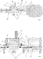
figure 1 shows a section view of a placing system of a plug according to the present invention; -
figure 2 shows an enlarged detail offigure 1 ; -
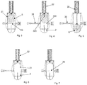
figures 3 to 7 show in succession a series of steps of a portion of the method according to the present invention. - In the appended figures the
reference numeral 1 refers to a placing system of astopper plug 6 in aperforation 7 in which a land consolidation material is present. Thissystem 1 is used in a jet grouting system. - The
system 1 comprises aconduit 2. Theconduit 2 extends at least in part outside theperforation 7. In particular, it extends along an imaginary prolongation of saidperforation 7. Theconduit 2 is typically straight. Theconduit 2 also extends inside theperforation 7. Theconduit 2 may comprise aconnection flange 71 connecting to afront wall 72 from which theperforation 7 extends. Typically this wall extends between the top and the bottom. - The
system 1 further comprises introduction means 3 for introducing theplug 6 into theconduit 2. The introduction means 3 may therefore define a loader of theplug 6. - The
system 1 further comprises a pusher member 4 of theplug 6. The pusher member 4 is movable along theconduit 2 so as to position theplug 6 in theperforation 7. In fact, by advancing along theconduit 2, the pusher member 4 pushes theplug 6 towards an end of the conduit that opens into saidperforation 7. Theplug 6 is typically inserted into theperforation 7 by interference. Typically, theplug 6 is deformable; thanks to this deformability it can be compressed transversely to an insertion direction in theperforation 7 and perform a sealing action on the walls of theperforation 7. As non-limiting examples, it could be made of rubber or polyurethane resin. - Advantageously the
plug 6 comprises a first and a secondaxial end plug 6 also comprises alateral surface 63 extending between the first and thesecond end - The
lateral surface 63 narrows as it passes from the first to thesecond end - The first
axial end 61 is destined to reach more deeply into saidperforation 7 with respect to the secondaxial end 62. Theplug 6 thus has a converging shape; for example, in the preferred solution thelateral surface 63 is truncoconical. - Advantageously the
system 1 comprises a perforation rod 5 for carrying out saidperforation 7. The rod 5 is movable along theconduit 2. - The
conduit 2 is a guide conduit of the perforation rod 5. It is also a guide conduit of theplug 6. The pusher member 4 coincides with/is a part of the perforation rod 5. The pusher member 4 is therefore integrated in the rod 5. There are no additional mechanical parts. - Advantageously, the introduction means 3 for introducing the
plug 6 in theconduit 2 comprise a containingtank 31 of theplug 6. Thetank 31 is located by a side of theconduit 2. Thetank 31 may comprise anoccludable opening 35 that allows loading theplug 6 in thetank 31 from outside the introduction means 3. - The introduction means 3 further comprise a
thrust actuator 32 suitable to move saidplug 6 from a first position in which it is located in thetank 31 to a second position in which it is located in theconduit 2. Thisthrust actuator 32 moves transversely (preferably orthogonally) to theconduit 2. Advantageously theactuator 32 is linear. It is typically fluid-dynamically driven. - The
thrust actuator 32 further comprises aconcavity 320 at one end destined to come into contact with and push theplug 6. Thisconcavity 320 is destined to at least partially house theplug 6. In particular, theconcavity 320 could be counter-shaped to a portion of theplug 6 with which it comes into contact. This allows to better transfer the thrust on theplug 6, minimising the risk that theplug 6 may slip or position itself in an undesired way. - The introduction means 3 comprise a dividing
wall 33 that is movable between a first configuration (seefigures 3 and 7 ) in which it separates saidtank 31 from theconduit 2 and a second configuration (seefigures 4, 5, 6 ) in which it allows communication between saidtank 31 and saidconduit 2. In the first configuration, the dividingwall 33 thus occludes acommunication passage 330 between theconduit 2 and thetank 31. The dividingwall 33 is a guillotine. In the second configuration, theplug 6 is allowed to pass from the tank to the conduit 2 (through the above-mentioned communication passage 330). - Advantageously, the introduction means 3 comprise a moving
device 34 suitable to move said dividingwall 33 between the first and the second configuration parallel to theconduit 2. Themoving device 34 can advantageously be driven fluid-dynamically. Themoving device 34 is a linear moving device. In the first configuration, the dividingwall 33 sealingly separates thetank 31 from theconduit 2. This allows preventing the consolidation material injected into theperforation 7 from dirtying thetank 31. This also prevents the consolidation material from dirtying theplug 6 before it is introduced into theconduit 2. - The
conduit 2 comprises astretch 22 in which the above-mentionedcommunication passage 330 is obtained. Thisstretch 22 of theconduit 2 is interposed between a first and asecond junction conduit 2 between which it is interposed. - The
conduit 2 advantageously also comprises a convergingsection 21 interposed between the above-mentionedcommunication passage 330 and oneend 23 of theconduit 2 destined to engage in theperforation 7. Advantageously, theplacing system 1 may also comprise radial sealing means between theconduit 2 and the rod 5. The radial sealing means comprise, for example: - a sealing element,
- pneumatic means that allow inflation; advantageously this makes it possible to come into contact with the
conduit 2 and the rod 5 and exert the radial seal. - This
passage 330 advantageously lies between the radial sealing means and an end of theconduit 2 opening into theperforation 7. - An object of the present invention is also a placing system of a
stopper plug 6 in aperforation 7 in which a land consolidation material is present. This material is typically fluid. This method is advantageously carried out by means of aplacing system 1 having one or more of the characteristics described above. The method comprises the step of extracting a perforation rod 5 from theperforation 7 while keeping the perforation rod 5 inside aconduit 2 that extends from saidperforation 7. Thisconduit 2 is advantageously straight. In particular, theconduit 2 is coaxial with theperforation 7. Advantageously, this step can be accompanied by a leakage of land mixed with the consolidation material from theperforation 7 in theconduit 2. In fact, it is not yet fully consolidated and is therefore movable. The consolidation material is typically a mixture comprising water and cement that mixes with the land. Advantageously theconduit 2 also extends inside theperforation 7. - The method further comprises the step of introducing the
plug 6 into theconduit 2, positioning theplug 6 between the perforation rod 5 and aninlet mouth 70 of theperforation 7. This occurs after extracting the rod 5 from theperforation 7. In particular, the step of introducing theplug 6 in theconduit 2 occurs after retracting the rod 5 so that a zone for introducing theplug 6 into theconduit 2 is interposed between the rod 5 and theperforation 7. - With particular reference to
figures 3-7 , the step of introducing theplug 6 in theconduit 2 comprises the sub-steps of (advantageouslyfigure 3 shows an initial situation at rest): - opening a dividing
wall 33 that separates atank 31 in which theplug 6 is placed from the conduit 2 (figure 4 ); - pushing the plug into the
conduit 2 by means of a thrust actuator 32 (figure 5 ). - These sub-steps are advantageously automated. In fact, they can be controlled sequentially by the operator with a single input.
- The method comprises the step of pushing the
plug 6 along theconduit 2 to fit theplug 6 into theinlet mouth 70 of theperforation 7. - The step of pushing the
plug 6 along theconduit 2 to fit theplug 6 into theinlet mouth 70 of theperforation 7 is carried out by pushing theplug 6 using the perforation rod 5. To perform the pushing step, the rod 5 is then moved along theconduit 2 and in particular approached and/or introduced into theinlet mouth 70 of theperforation 7. - After or during the step of pushing the plug, the method may comprise the steps of:
- recalling said
thrust actuator 32 by extracting it from theconduit 2, advantageously positioning it in the tank 31 (figure 6 ); - closing the dividing wall 33 (
figure 7 ). - These steps are advantageously automated. In fact, they can be controlled sequentially by the operator with a single input.
- An object of the present invention is also a method for land consolidation. This land consolidation method comprises the step of implementing a placing method of a
plug 6 having one or more of the steps described above. Prior to the step of implementing said placing method of theplug 6, the land consolidation method comprises the step of carrying out aperforation 7; advantageously, the step of carrying out theperforation 7 is carried out using the perforation rod 5. - The method further comprises the step of dispensing consolidation material inside the
perforation 7. The step of dispensing the consolidation material takes place using at least adispenser 50 located along the perforation rod 5. In particular this occurs during at least a part of a stroke of the rod 5 which moves from a bottom of saidperforation 7 towards theinlet mouth 70 of theperforation 7. - The dispensed consolidation material advantageously comprises a cementitious material (other components may then be present e.g. a grip accelerator). The step of dispensing the consolidation material comprises the step of dispensing a pressurised jet that breaks down the surrounding land. The consolidation material will then mix with the surrounding land to form a columnar volume that reinforces the land (especially if several columnar volumes are made connected to each other, each obtained by a corresponding perforation). Advantageously, during at least a part of the step of dispensing the consolidation material, the method comprises the step of rotating said rod 5 around an axis of longitudinal extension of said rod. Advantageously, the step of dispensing the consolidation material can be carried out simultaneously by means of a plurality of nozzles, typically orientated along different dispensing directions (possibly they could also be diametrically opposite).
- Advantageously near the
inlet mouth 70 of theperforation 7, the consolidation method involves stopping the step of dispensing the consolidation material. Thus, a first stretch of theperforation 7 has a reduced section, with respect to a second stretch of the perforation in which the land has been broken down by the step of dispensing the consolidation material. The first stretch also comprises theinlet mouth 70 of theperforation 7. - For example, the
inlet mouth 70 of theperforation 7 is formed on an artificial wall. For example, theperforation 7 could extend from awall 72 that extends between the top and bottom and defines the front of a tunnel under construction. This front is then coated with a layer of concrete or other material for safety. - In the preferred solution, the
perforation 7 extends along a straight segment. - Advantageously, this straight segment has a horizontal component which is greater than the vertical one (meaning that the vertical component could also be zero). Preferably the
inlet mouth 70 is located at a lower height or at the same height as the bottom of the perforation. Theperforation 7 therefore extends horizontally or upwards (preferably slightly upwards). If necessary, the perforation could also extend downwards (if below a water head). - The present invention achieves important advantages.
- First, it allows to plug a hole in a
perforation 7 into which a consolidation material has been introduced by minimising the quantity of consolidation material that leaks due to the pressure present in theperforation 7. This is particularly important if theperforation 7 is carried out in a water-rich area, which increases the mobility of the consolidation material mixed with the land. Secondly, it allows the plugging to be carried out in conditions of maximum safety for the operator. - The invention as it is conceived is susceptible to numerous modifications and variations, all falling within the scope of the inventive concept characterising it. Furthermore, all the details can be replaced with other technically equivalent elements. In practice, all the materials used, as well as the dimensions, can be any according to requirements.
Claims (10)
- A method for soil consolidation and/or impermeabilisation, comprising the steps of:i) making a perforation (4) in the soil by means of a drilling rod (2);ii) dispensing under pressure in the perforation (4), by means of said drilling rod (2):- a fluid operating material (31) for consolidation and/or impermeabilisation which operates by disintegrating and mixing with the soil to form a columnar volume; and- a fluid accelerating material (32) for accelerating the consolidation and/or impermeabilisation;iii) performing an extraction of the rod (2) from said perforation (4); the step of dispensing in the perforation (4) by means of said drilling rod (2) the fluid operating material (31) and the fluid accelerating material (32) occurring during the step of performing said extraction and generating a soil consolidation and/or impermeabilisation;characterised in that said step of dispensing in the perforation (4) a fluid operating material (31) and a fluid accelerating material (32) comprises the step of feeding a first and a second dispenser (21, 22) formed on said rod (2) respectively with the fluid operating material (31) and the fluid accelerating material (32); the step of feeding the first and the second dispenser (21, 22) occurring while keeping the fluid operating material (31) and the fluid accelerating material (32) separate.
- The method according to claim 1, characterised in that said fluid accelerating material (32) comprises a mixture comprising a diluent and an active accelerant ingredient; the step of dispensing the fluid operating material (31) and the fluid accelerating material (32) in the perforation (4) by means of said rod (2) comprises the sub-step of dispensing within a unit of time a quantity of said active accelerant ingredient that at least in a first position of the rod (2) is less than at least a second position of the drilling rod (2);
in said second position the drilling rod (2) being more extracted from said perforation (4) than in the first position. - The method according to claim 2, characterised in that the step of dispensing the fluid operating material (31) and the fluid accelerating material (32) occurs during an extraction stroke of the rod (2) from the perforation (4); the rod (2) assuming the first position at the beginning of said step of dispensing the fluid operating material (31) and the fluid accelerating material (32); the rod (2) assuming the second position at the end of the step of dispensing the fluid operating material (31) and the fluid accelerating material (32); the amount of said active ingredient dispensed within a unit of time in the second position is more than double the amount of said active ingredient dispensed in the unit of time in the first position.
- The method according to claim 1, characterised in that said fluid accelerating material (32) comprises a mixture comprising a diluent and an active accelerant ingredient; the step of dispensing a fluid operating material (31) and a fluid accelerating material (32) in the perforation (4) through said drilling rod (2) comprises the step of progressively increasing the amount of active accelerant ingredient dispensed within the unit of time by the rod (2) during at least a predetermined portion of the extraction of the rod (2).
- The method according to claim 2 or 3 or 4, characterised in that said active accelerant ingredient is sodium silicate and said fluid operating material (31) is a cementitious material.
- The method according to any one of the preceding claims, characterised in that it comprises a step of:- collecting said fluid operating material (31) from a first tank (25) and conveying it internally to said drilling rod (2) through a first line (23) which feeds the first dispenser (21);- collecting said fluid accelerating material (32) from a second tank (26) and conveying it internally to said drilling rod (2) through a second line (24) which feeds the second dispenser (22).
- The method according to claim 6 when directly or indirectly dependent on claim 2 or 3 or 4 or 5, characterised in that it comprises, during at least a part of the extraction of the rod (2), the step of adding to the accelerating material (32) already present in the second tank (26) a further active accelerant ingredient.
- The method according to claim 6 or 7, characterised in that during the step of performing an extraction of the rod (2) from the perforation (4), the first line (23) is traversed exclusively by the fluid operating material (31) and the second line (24) is traversed exclusively by the fluid accelerating material (32); the fluid operating material (31) and the fluid accelerating material (32) coming into mutual communication only downstream of the rod (2) or in output from the rod (2), mixing with the soil surrounding the rod (2).
- The method according to any one of the preceding claims, characterised in that the step of dispensing the fluid operating material (31) in the perforation (4) occurs by spraying said fluid operating material (31) at more than 350 bar; the step of dispensing the fluid accelerating material (32) in the perforation (4) occurring by spraying said fluid accelerating material (32) at a pressure comprised between 20 and 200 bar.
- A system for soil consolidation and/or impermeabilisation characterised in that it comprises:- a drilling rod (2) comprising a first dispenser (21) and a second dispenser (22);- a first tank (25) containing a fluid operating material (31) for soil consolidation and/or impermeabilisation; said first tank (25) being connected to said first dispenser (21) through a first line (23);- a dosing system of a fluid accelerating material (32) for accelerating soil consolidation/impermeabilisation; said dosing system being connected to the second dispenser (22) through a second line (24).
Priority Applications (1)
| Application Number | Priority Date | Filing Date | Title |
|---|---|---|---|
| EP20206760.9A EP3808903A1 (en) | 2019-05-27 | 2020-04-27 | A placing system and method of a stopper plug in a perforation |
Applications Claiming Priority (1)
| Application Number | Priority Date | Filing Date | Title |
|---|---|---|---|
| IT102019000007254A IT201900007254A1 (en) | 2019-05-27 | 2019-05-27 | System and method of laying an occlusion plug of a perforation |
Related Child Applications (2)
| Application Number | Title | Priority Date | Filing Date |
|---|---|---|---|
| EP20206760.9A Division-Into EP3808903A1 (en) | 2019-05-27 | 2020-04-27 | A placing system and method of a stopper plug in a perforation |
| EP20206760.9A Division EP3808903A1 (en) | 2019-05-27 | 2020-04-27 | A placing system and method of a stopper plug in a perforation |
Publications (2)
| Publication Number | Publication Date |
|---|---|
| EP3744902A2 true EP3744902A2 (en) | 2020-12-02 |
| EP3744902A3 EP3744902A3 (en) | 2021-02-17 |
Family
ID=68234060
Family Applications (2)
| Application Number | Title | Priority Date | Filing Date |
|---|---|---|---|
| EP20171550.5A Withdrawn EP3744902A3 (en) | 2019-05-27 | 2020-04-27 | A method for soil consolidation |
| EP20206760.9A Withdrawn EP3808903A1 (en) | 2019-05-27 | 2020-04-27 | A placing system and method of a stopper plug in a perforation |
Family Applications After (1)
| Application Number | Title | Priority Date | Filing Date |
|---|---|---|---|
| EP20206760.9A Withdrawn EP3808903A1 (en) | 2019-05-27 | 2020-04-27 | A placing system and method of a stopper plug in a perforation |
Country Status (3)
| Country | Link |
|---|---|
| EP (2) | EP3744902A3 (en) |
| DE (1) | DE202020005620U1 (en) |
| IT (1) | IT201900007254A1 (en) |
Family Cites Families (12)
| Publication number | Priority date | Publication date | Assignee | Title |
|---|---|---|---|---|
| US1764948A (en) * | 1929-06-14 | 1930-06-17 | Frankignoul Pieux Armes | Method for driving lining tubes for molding concrete piles in the ground |
| DE1634565B2 (en) * | 1964-05-22 | 1973-02-08 | Schdruzeni kamenouhelnych dolu, Kladno (Tschechoslowakei) | INJECTION DEVICE FOR INJECTING TWO REACTING LIQUIDS TO SEAL THE BUILDING GROUND |
| JPS634115A (en) * | 1986-06-24 | 1988-01-09 | Kyokado Eng Co Ltd | Ground-injecting construction |
| DE3718631A1 (en) * | 1987-06-03 | 1988-12-22 | Gkn Keller Gmbh | Combined injection method as well as apparatus for producing a highly consolidated soil volume while simultaneously stabilising the adjacent soil |
| JP2001164589A (en) * | 1999-12-08 | 2001-06-19 | Shimizu Corp | Construction method for high pressure gas storage facility |
| US9169611B2 (en) * | 2000-06-15 | 2015-10-27 | Geopier Foundation Company, Inc. | Method and apparatus for building support piers from one or more successive lifts formed in a soil matrix |
| JP3626972B1 (en) * | 2003-10-02 | 2005-03-09 | 栄興産業株式会社 | Jet stirring method and jet stirring device |
| KR100776304B1 (en) * | 2006-05-25 | 2007-11-16 | 정진교 | Direct punching simultaneous poruing equipment and grouting construction method |
| DE102007023736B4 (en) * | 2007-05-22 | 2011-01-20 | Bauer Spezialtiefbau Gmbh | Fast setting HDI |
| KR101082528B1 (en) * | 2009-12-22 | 2011-11-10 | 김성희 | Packer for ground anchor and wire holding device using the same |
| KR101545254B1 (en) * | 2014-08-28 | 2015-08-20 | 최정옥 | Medium Pressure Grouting device and it's using a columnar structure construction method |
| KR101552466B1 (en) * | 2014-11-26 | 2015-09-10 | 윤택규 | Apparatus for ground reinforcement and ground reinforcement method using the same |
-
2019
- 2019-05-27 IT IT102019000007254A patent/IT201900007254A1/en unknown
-
2020
- 2020-04-27 EP EP20171550.5A patent/EP3744902A3/en not_active Withdrawn
- 2020-04-27 EP EP20206760.9A patent/EP3808903A1/en not_active Withdrawn
- 2020-04-27 DE DE202020005620.0U patent/DE202020005620U1/en active Active
Also Published As
| Publication number | Publication date |
|---|---|
| EP3744902A3 (en) | 2021-02-17 |
| IT201900007254A1 (en) | 2020-11-27 |
| DE202020005620U1 (en) | 2021-11-02 |
| EP3808903A1 (en) | 2021-04-21 |
Similar Documents
| Publication | Publication Date | Title |
|---|---|---|
| EP1745840A1 (en) | Apparatus and method for mixing a liquid material and a flowable powdery material to obtain a slurry | |
| CA2104844C (en) | Long hole chemical grout injector system | |
| KR101664366B1 (en) | concrete cleaning apparatus for concrete pumping car and preparing method for the same | |
| EP3744902A2 (en) | A method for soil consolidation | |
| EP0894723A1 (en) | Bag filling valve for viscous fluids | |
| EP3129744B1 (en) | Method and arrangement for providing explosive charging into a bore hole | |
| CN116391072A (en) | Apparatus, mining machine and method for resin injection | |
| JP5824588B1 (en) | Vacuum grout injection method | |
| CA1048927A (en) | Plug for injection | |
| CN106320355B (en) | A kind of rich water karst area mixes the ejection for water plugging method of more slurries | |
| CN102392633A (en) | New method for releasing underground radioactive tracer and device thereof | |
| CN109072697B (en) | Method and apparatus for rock reinforcement | |
| SK283910B6 (en) | Method for creating thin walls in the ground | |
| JP3961510B2 (en) | Ground injection method | |
| EP3733974A1 (en) | A method and a system for soil consolidation and/or impermeabilisation | |
| US1478865A (en) | Machine for injecting plastic materials | |
| CN209555927U (en) | The mini-valve tube of two fluid grouting core pipe design | |
| US4497578A (en) | Machine for mixing and injecting water and grout into a roof bolt hole | |
| KR101550158B1 (en) | PC concrete block using perpendicular hall constructions method and apparatus | |
| CN108590621B (en) | System and method for high-pressure sand adding after hydraulic fracturing remote continuous pump in coal mine | |
| CN210508412U (en) | Automatic sleeve grout defect prosthetic devices of accuse volume | |
| KR100974075B1 (en) | Method and automatic stopper unit of horizontal high velocity blast shaking for use in construction of tunnel etc. | |
| KR102420953B1 (en) | Grouting method using a simultaneous injection steel pipe grouting device | |
| US3484082A (en) | Apparatus for automatically injecting mixtures into the ground | |
| EP0011429B1 (en) | Treating soils by injecting grout |
Legal Events
| Date | Code | Title | Description |
|---|---|---|---|
| PUAI | Public reference made under article 153(3) epc to a published international application that has entered the european phase |
Free format text: ORIGINAL CODE: 0009012 |
|
| STAA | Information on the status of an ep patent application or granted ep patent |
Free format text: STATUS: THE APPLICATION HAS BEEN PUBLISHED |
|
| AK | Designated contracting states |
Kind code of ref document: A2 Designated state(s): AL AT BE BG CH CY CZ DE DK EE ES FI FR GB GR HR HU IE IS IT LI LT LU LV MC MK MT NL NO PL PT RO RS SE SI SK SM TR |
|
| AX | Request for extension of the european patent |
Extension state: BA ME |
|
| PUAL | Search report despatched |
Free format text: ORIGINAL CODE: 0009013 |
|
| AK | Designated contracting states |
Kind code of ref document: A3 Designated state(s): AL AT BE BG CH CY CZ DE DK EE ES FI FR GB GR HR HU IE IS IT LI LT LU LV MC MK MT NL NO PL PT RO RS SE SI SK SM TR |
|
| AX | Request for extension of the european patent |
Extension state: BA ME |
|
| RIC1 | Information provided on ipc code assigned before grant |
Ipc: C09K 17/10 20060101ALI20210111BHEP Ipc: E02D 5/46 20060101ALI20210111BHEP Ipc: E02D 5/66 20060101ALI20210111BHEP Ipc: C09K 17/12 20060101ALI20210111BHEP Ipc: E02D 31/10 20060101AFI20210111BHEP Ipc: E02D 37/00 20060101ALI20210111BHEP Ipc: E02D 3/12 20060101ALI20210111BHEP |
|
| STAA | Information on the status of an ep patent application or granted ep patent |
Free format text: STATUS: THE APPLICATION IS DEEMED TO BE WITHDRAWN |
|
| 18D | Application deemed to be withdrawn |
Effective date: 20210818 |