EP3743584B1 - Dispositif d'écartement pour vitrages isolants doté du câble plat intégré - Google Patents
Dispositif d'écartement pour vitrages isolants doté du câble plat intégré Download PDFInfo
- Publication number
- EP3743584B1 EP3743584B1 EP19700600.0A EP19700600A EP3743584B1 EP 3743584 B1 EP3743584 B1 EP 3743584B1 EP 19700600 A EP19700600 A EP 19700600A EP 3743584 B1 EP3743584 B1 EP 3743584B1
- Authority
- EP
- European Patent Office
- Prior art keywords
- pane
- spacer
- glazing
- ribbon cable
- cable
- Prior art date
- Legal status (The legal status is an assumption and is not a legal conclusion. Google has not performed a legal analysis and makes no representation as to the accuracy of the status listed.)
- Active
Links
- 125000006850 spacer group Chemical group 0.000 title claims description 170
- 239000010410 layer Substances 0.000 claims description 93
- 230000004888 barrier function Effects 0.000 claims description 64
- 239000000565 sealant Substances 0.000 claims description 28
- 229910052751 metal Inorganic materials 0.000 claims description 24
- 239000002184 metal Substances 0.000 claims description 24
- 239000011888 foil Substances 0.000 claims description 21
- 238000000034 method Methods 0.000 claims description 17
- 238000004519 manufacturing process Methods 0.000 claims description 10
- 239000013047 polymeric layer Substances 0.000 claims description 10
- 239000004983 Polymer Dispersed Liquid Crystal Substances 0.000 claims description 4
- 239000010408 film Substances 0.000 description 55
- 239000004020 conductor Substances 0.000 description 52
- 229920000642 polymer Polymers 0.000 description 37
- 238000009413 insulation Methods 0.000 description 30
- -1 polyethylene Polymers 0.000 description 15
- 239000007789 gas Substances 0.000 description 14
- 239000000853 adhesive Substances 0.000 description 13
- 230000001070 adhesive effect Effects 0.000 description 13
- RYGMFSIKBFXOCR-UHFFFAOYSA-N Copper Chemical compound [Cu] RYGMFSIKBFXOCR-UHFFFAOYSA-N 0.000 description 11
- 238000013461 design Methods 0.000 description 11
- 239000002274 desiccant Substances 0.000 description 10
- 239000011521 glass Substances 0.000 description 10
- 239000000463 material Substances 0.000 description 9
- 230000005540 biological transmission Effects 0.000 description 8
- 239000000203 mixture Substances 0.000 description 8
- 229910052782 aluminium Inorganic materials 0.000 description 7
- XAGFODPZIPBFFR-UHFFFAOYSA-N aluminium Chemical compound [Al] XAGFODPZIPBFFR-UHFFFAOYSA-N 0.000 description 7
- 239000000919 ceramic Substances 0.000 description 7
- 238000009434 installation Methods 0.000 description 7
- 229920003023 plastic Polymers 0.000 description 7
- 239000004033 plastic Substances 0.000 description 7
- 229920000139 polyethylene terephthalate Polymers 0.000 description 7
- 239000005020 polyethylene terephthalate Substances 0.000 description 7
- 239000004698 Polyethylene Substances 0.000 description 6
- 238000000576 coating method Methods 0.000 description 6
- 239000011889 copper foil Substances 0.000 description 6
- 238000010292 electrical insulation Methods 0.000 description 6
- 239000003365 glass fiber Substances 0.000 description 6
- 230000003287 optical effect Effects 0.000 description 6
- 229920000573 polyethylene Polymers 0.000 description 6
- 238000003466 welding Methods 0.000 description 6
- 229920002367 Polyisobutene Polymers 0.000 description 5
- 230000008901 benefit Effects 0.000 description 5
- 229920001577 copolymer Polymers 0.000 description 5
- 229910052802 copper Inorganic materials 0.000 description 5
- 239000010949 copper Substances 0.000 description 5
- 150000002500 ions Chemical class 0.000 description 5
- 239000002245 particle Substances 0.000 description 5
- 239000004417 polycarbonate Substances 0.000 description 5
- 229920000515 polycarbonate Polymers 0.000 description 5
- 229920001296 polysiloxane Polymers 0.000 description 5
- 229920002635 polyurethane Polymers 0.000 description 5
- 239000004814 polyurethane Substances 0.000 description 5
- XKRFYHLGVUSROY-UHFFFAOYSA-N Argon Chemical compound [Ar] XKRFYHLGVUSROY-UHFFFAOYSA-N 0.000 description 4
- 239000004743 Polypropylene Substances 0.000 description 4
- 238000004026 adhesive bonding Methods 0.000 description 4
- 239000012790 adhesive layer Substances 0.000 description 4
- 239000011248 coating agent Substances 0.000 description 4
- 238000011049 filling Methods 0.000 description 4
- 239000004973 liquid crystal related substance Substances 0.000 description 4
- 229920001155 polypropylene Polymers 0.000 description 4
- 238000012545 processing Methods 0.000 description 4
- 238000007789 sealing Methods 0.000 description 4
- 239000004945 silicone rubber Substances 0.000 description 4
- 238000012546 transfer Methods 0.000 description 4
- XEEYBQQBJWHFJM-UHFFFAOYSA-N Iron Chemical compound [Fe] XEEYBQQBJWHFJM-UHFFFAOYSA-N 0.000 description 3
- BQCADISMDOOEFD-UHFFFAOYSA-N Silver Chemical compound [Ag] BQCADISMDOOEFD-UHFFFAOYSA-N 0.000 description 3
- 239000011324 bead Substances 0.000 description 3
- 230000007547 defect Effects 0.000 description 3
- 230000036961 partial effect Effects 0.000 description 3
- 229920000058 polyacrylate Polymers 0.000 description 3
- 229920001707 polybutylene terephthalate Polymers 0.000 description 3
- 229920000728 polyester Polymers 0.000 description 3
- 230000008569 process Effects 0.000 description 3
- 230000002829 reductive effect Effects 0.000 description 3
- 229920002379 silicone rubber Polymers 0.000 description 3
- 229910052709 silver Inorganic materials 0.000 description 3
- 239000004332 silver Substances 0.000 description 3
- 238000005476 soldering Methods 0.000 description 3
- XLYOFNOQVPJJNP-UHFFFAOYSA-N water Substances O XLYOFNOQVPJJNP-UHFFFAOYSA-N 0.000 description 3
- 239000004952 Polyamide Substances 0.000 description 2
- 238000010521 absorption reaction Methods 0.000 description 2
- 239000004676 acrylonitrile butadiene styrene Substances 0.000 description 2
- 229910045601 alloy Inorganic materials 0.000 description 2
- 239000000956 alloy Substances 0.000 description 2
- 229910052786 argon Inorganic materials 0.000 description 2
- 229920005549 butyl rubber Polymers 0.000 description 2
- QXJJQWWVWRCVQT-UHFFFAOYSA-K calcium;sodium;phosphate Chemical compound [Na+].[Ca+2].[O-]P([O-])([O-])=O QXJJQWWVWRCVQT-UHFFFAOYSA-K 0.000 description 2
- 150000001875 compounds Chemical class 0.000 description 2
- 238000004132 cross linking Methods 0.000 description 2
- 238000001125 extrusion Methods 0.000 description 2
- 239000005329 float glass Substances 0.000 description 2
- PCHJSUWPFVWCPO-UHFFFAOYSA-N gold Chemical compound [Au] PCHJSUWPFVWCPO-UHFFFAOYSA-N 0.000 description 2
- 229910052737 gold Inorganic materials 0.000 description 2
- 239000010931 gold Substances 0.000 description 2
- 239000011261 inert gas Substances 0.000 description 2
- 229910052742 iron Inorganic materials 0.000 description 2
- 238000010030 laminating Methods 0.000 description 2
- 238000003475 lamination Methods 0.000 description 2
- 239000011159 matrix material Substances 0.000 description 2
- 238000005240 physical vapour deposition Methods 0.000 description 2
- 239000002985 plastic film Substances 0.000 description 2
- 229920006255 plastic film Polymers 0.000 description 2
- 229920002647 polyamide Polymers 0.000 description 2
- 238000009417 prefabrication Methods 0.000 description 2
- 238000003825 pressing Methods 0.000 description 2
- 239000005336 safety glass Substances 0.000 description 2
- 239000003566 sealing material Substances 0.000 description 2
- LIVNPJMFVYWSIS-UHFFFAOYSA-N silicon monoxide Chemical class [Si-]#[O+] LIVNPJMFVYWSIS-UHFFFAOYSA-N 0.000 description 2
- 229910052814 silicon oxide Inorganic materials 0.000 description 2
- 229920001169 thermoplastic Polymers 0.000 description 2
- 239000004416 thermosoftening plastic Substances 0.000 description 2
- 229920006942 ABS/PC Polymers 0.000 description 1
- PNEYBMLMFCGWSK-UHFFFAOYSA-N Alumina Chemical class [O-2].[O-2].[O-2].[Al+3].[Al+3] PNEYBMLMFCGWSK-UHFFFAOYSA-N 0.000 description 1
- VYZAMTAEIAYCRO-UHFFFAOYSA-N Chromium Chemical compound [Cr] VYZAMTAEIAYCRO-UHFFFAOYSA-N 0.000 description 1
- 229910000881 Cu alloy Inorganic materials 0.000 description 1
- 229920002943 EPDM rubber Polymers 0.000 description 1
- IMROMDMJAWUWLK-UHFFFAOYSA-N Ethenol Chemical compound OC=C IMROMDMJAWUWLK-UHFFFAOYSA-N 0.000 description 1
- 229920000219 Ethylene vinyl alcohol Polymers 0.000 description 1
- 239000004831 Hot glue Substances 0.000 description 1
- 229920002319 Poly(methyl acrylate) Polymers 0.000 description 1
- 239000005062 Polybutadiene Substances 0.000 description 1
- 239000004642 Polyimide Substances 0.000 description 1
- 239000004721 Polyphenylene oxide Substances 0.000 description 1
- 239000004793 Polystyrene Substances 0.000 description 1
- 229920001328 Polyvinylidene chloride Polymers 0.000 description 1
- VYPSYNLAJGMNEJ-UHFFFAOYSA-N Silicium dioxide Chemical compound O=[Si]=O VYPSYNLAJGMNEJ-UHFFFAOYSA-N 0.000 description 1
- ATJFFYVFTNAWJD-UHFFFAOYSA-N Tin Chemical compound [Sn] ATJFFYVFTNAWJD-UHFFFAOYSA-N 0.000 description 1
- XHCLAFWTIXFWPH-UHFFFAOYSA-N [O-2].[O-2].[O-2].[O-2].[O-2].[V+5].[V+5] Chemical compound [O-2].[O-2].[O-2].[O-2].[O-2].[V+5].[V+5] XHCLAFWTIXFWPH-UHFFFAOYSA-N 0.000 description 1
- XECAHXYUAAWDEL-UHFFFAOYSA-N acrylonitrile butadiene styrene Chemical compound C=CC=C.C=CC#N.C=CC1=CC=CC=C1 XECAHXYUAAWDEL-UHFFFAOYSA-N 0.000 description 1
- 229920000122 acrylonitrile butadiene styrene Polymers 0.000 description 1
- 150000008360 acrylonitriles Chemical class 0.000 description 1
- 238000004378 air conditioning Methods 0.000 description 1
- 230000033228 biological regulation Effects 0.000 description 1
- 239000005388 borosilicate glass Substances 0.000 description 1
- 238000009435 building construction Methods 0.000 description 1
- DQXBYHZEEUGOBF-UHFFFAOYSA-N but-3-enoic acid;ethene Chemical compound C=C.OC(=O)CC=C DQXBYHZEEUGOBF-UHFFFAOYSA-N 0.000 description 1
- 230000008859 change Effects 0.000 description 1
- 229910052804 chromium Inorganic materials 0.000 description 1
- 239000011651 chromium Substances 0.000 description 1
- 230000001419 dependent effect Effects 0.000 description 1
- 238000000151 deposition Methods 0.000 description 1
- 238000011161 development Methods 0.000 description 1
- 238000009826 distribution Methods 0.000 description 1
- 230000009977 dual effect Effects 0.000 description 1
- 229920001971 elastomer Polymers 0.000 description 1
- 238000004870 electrical engineering Methods 0.000 description 1
- 238000005265 energy consumption Methods 0.000 description 1
- 230000007613 environmental effect Effects 0.000 description 1
- 239000005038 ethylene vinyl acetate Substances 0.000 description 1
- 239000004715 ethylene vinyl alcohol Substances 0.000 description 1
- 238000009422 external insulation Methods 0.000 description 1
- 238000000227 grinding Methods 0.000 description 1
- 238000009499 grossing Methods 0.000 description 1
- 238000010438 heat treatment Methods 0.000 description 1
- RZXDTJIXPSCHCI-UHFFFAOYSA-N hexa-1,5-diene-2,5-diol Chemical compound OC(=C)CCC(O)=C RZXDTJIXPSCHCI-UHFFFAOYSA-N 0.000 description 1
- 230000006872 improvement Effects 0.000 description 1
- 238000010348 incorporation Methods 0.000 description 1
- 230000010354 integration Effects 0.000 description 1
- 238000002955 isolation Methods 0.000 description 1
- 229910052743 krypton Inorganic materials 0.000 description 1
- DNNSSWSSYDEUBZ-UHFFFAOYSA-N krypton atom Chemical compound [Kr] DNNSSWSSYDEUBZ-UHFFFAOYSA-N 0.000 description 1
- 230000031700 light absorption Effects 0.000 description 1
- 238000004020 luminiscence type Methods 0.000 description 1
- 238000010297 mechanical methods and process Methods 0.000 description 1
- 230000005226 mechanical processes and functions Effects 0.000 description 1
- 229910001092 metal group alloy Inorganic materials 0.000 description 1
- 150000002739 metals Chemical class 0.000 description 1
- 230000005012 migration Effects 0.000 description 1
- 238000013508 migration Methods 0.000 description 1
- 238000003801 milling Methods 0.000 description 1
- 238000012986 modification Methods 0.000 description 1
- 230000004048 modification Effects 0.000 description 1
- 239000002808 molecular sieve Substances 0.000 description 1
- 125000005487 naphthalate group Chemical group 0.000 description 1
- QGLKJKCYBOYXKC-UHFFFAOYSA-N nonaoxidotritungsten Chemical compound O=[W]1(=O)O[W](=O)(=O)O[W](=O)(=O)O1 QGLKJKCYBOYXKC-UHFFFAOYSA-N 0.000 description 1
- 230000000414 obstructive effect Effects 0.000 description 1
- 238000005457 optimization Methods 0.000 description 1
- 150000008116 organic polysulfides Chemical class 0.000 description 1
- 230000000149 penetrating effect Effects 0.000 description 1
- 230000035515 penetration Effects 0.000 description 1
- 229920001200 poly(ethylene-vinyl acetate) Polymers 0.000 description 1
- 229920003229 poly(methyl methacrylate) Polymers 0.000 description 1
- 229920002857 polybutadiene Polymers 0.000 description 1
- 229920000570 polyether Polymers 0.000 description 1
- 229920001721 polyimide Polymers 0.000 description 1
- 239000004926 polymethyl methacrylate Substances 0.000 description 1
- 229920005554 polynitrile Polymers 0.000 description 1
- 229920006124 polyolefin elastomer Polymers 0.000 description 1
- 229920002223 polystyrene Polymers 0.000 description 1
- 229920001021 polysulfide Polymers 0.000 description 1
- 239000005077 polysulfide Substances 0.000 description 1
- 150000008117 polysulfides Polymers 0.000 description 1
- 239000004800 polyvinyl chloride Substances 0.000 description 1
- 229920000915 polyvinyl chloride Polymers 0.000 description 1
- 239000005033 polyvinylidene chloride Substances 0.000 description 1
- 238000007639 printing Methods 0.000 description 1
- 230000001681 protective effect Effects 0.000 description 1
- 239000011241 protective layer Substances 0.000 description 1
- 230000002441 reversible effect Effects 0.000 description 1
- 229920002631 room-temperature vulcanizate silicone Polymers 0.000 description 1
- 239000005060 rubber Substances 0.000 description 1
- 238000007790 scraping Methods 0.000 description 1
- 229910052710 silicon Inorganic materials 0.000 description 1
- 239000010703 silicon Substances 0.000 description 1
- 239000003707 silyl modified polymer Substances 0.000 description 1
- 239000002356 single layer Substances 0.000 description 1
- 239000005361 soda-lime glass Substances 0.000 description 1
- URGAHOPLAPQHLN-UHFFFAOYSA-N sodium aluminosilicate Chemical compound [Na+].[Al+3].[O-][Si]([O-])=O.[O-][Si]([O-])=O URGAHOPLAPQHLN-UHFFFAOYSA-N 0.000 description 1
- 239000007787 solid Substances 0.000 description 1
- 230000006641 stabilisation Effects 0.000 description 1
- 238000011105 stabilization Methods 0.000 description 1
- 238000003860 storage Methods 0.000 description 1
- 229920000638 styrene acrylonitrile Polymers 0.000 description 1
- 239000011145 styrene acrylonitrile resin Substances 0.000 description 1
- 239000000126 substance Substances 0.000 description 1
- 230000037072 sun protection Effects 0.000 description 1
- 239000010409 thin film Substances 0.000 description 1
- 229910052718 tin Inorganic materials 0.000 description 1
- 239000011135 tin Substances 0.000 description 1
- 239000005341 toughened glass Substances 0.000 description 1
- 229910001930 tungsten oxide Inorganic materials 0.000 description 1
- 229910001935 vanadium oxide Inorganic materials 0.000 description 1
- 239000013585 weight reducing agent Substances 0.000 description 1
Images


Classifications
-
- E—FIXED CONSTRUCTIONS
- E06—DOORS, WINDOWS, SHUTTERS, OR ROLLER BLINDS IN GENERAL; LADDERS
- E06B—FIXED OR MOVABLE CLOSURES FOR OPENINGS IN BUILDINGS, VEHICLES, FENCES OR LIKE ENCLOSURES IN GENERAL, e.g. DOORS, WINDOWS, BLINDS, GATES
- E06B3/00—Window sashes, door leaves, or like elements for closing wall or like openings; Layout of fixed or moving closures, e.g. windows in wall or like openings; Features of rigidly-mounted outer frames relating to the mounting of wing frames
- E06B3/66—Units comprising two or more parallel glass or like panes permanently secured together
- E06B3/663—Elements for spacing panes
- E06B3/66309—Section members positioned at the edges of the glazing unit
- E06B3/66314—Section members positioned at the edges of the glazing unit of tubular shape
-
- E—FIXED CONSTRUCTIONS
- E06—DOORS, WINDOWS, SHUTTERS, OR ROLLER BLINDS IN GENERAL; LADDERS
- E06B—FIXED OR MOVABLE CLOSURES FOR OPENINGS IN BUILDINGS, VEHICLES, FENCES OR LIKE ENCLOSURES IN GENERAL, e.g. DOORS, WINDOWS, BLINDS, GATES
- E06B3/00—Window sashes, door leaves, or like elements for closing wall or like openings; Layout of fixed or moving closures, e.g. windows in wall or like openings; Features of rigidly-mounted outer frames relating to the mounting of wing frames
- E06B3/66—Units comprising two or more parallel glass or like panes permanently secured together
- E06B3/673—Assembling the units
- E06B3/67326—Assembling spacer elements with the panes
-
- E—FIXED CONSTRUCTIONS
- E06—DOORS, WINDOWS, SHUTTERS, OR ROLLER BLINDS IN GENERAL; LADDERS
- E06B—FIXED OR MOVABLE CLOSURES FOR OPENINGS IN BUILDINGS, VEHICLES, FENCES OR LIKE ENCLOSURES IN GENERAL, e.g. DOORS, WINDOWS, BLINDS, GATES
- E06B3/00—Window sashes, door leaves, or like elements for closing wall or like openings; Layout of fixed or moving closures, e.g. windows in wall or like openings; Features of rigidly-mounted outer frames relating to the mounting of wing frames
- E06B3/66—Units comprising two or more parallel glass or like panes permanently secured together
- E06B3/663—Elements for spacing panes
- E06B3/66309—Section members positioned at the edges of the glazing unit
- E06B2003/6638—Section members positioned at the edges of the glazing unit with coatings
-
- E—FIXED CONSTRUCTIONS
- E06—DOORS, WINDOWS, SHUTTERS, OR ROLLER BLINDS IN GENERAL; LADDERS
- E06B—FIXED OR MOVABLE CLOSURES FOR OPENINGS IN BUILDINGS, VEHICLES, FENCES OR LIKE ENCLOSURES IN GENERAL, e.g. DOORS, WINDOWS, BLINDS, GATES
- E06B3/00—Window sashes, door leaves, or like elements for closing wall or like openings; Layout of fixed or moving closures, e.g. windows in wall or like openings; Features of rigidly-mounted outer frames relating to the mounting of wing frames
- E06B3/66—Units comprising two or more parallel glass or like panes permanently secured together
- E06B3/663—Elements for spacing panes
- E06B3/66309—Section members positioned at the edges of the glazing unit
- E06B3/66342—Section members positioned at the edges of the glazing unit characterised by their sealed connection to the panes
- E06B3/66347—Section members positioned at the edges of the glazing unit characterised by their sealed connection to the panes with integral grooves or rabbets for holding the panes
-
- E—FIXED CONSTRUCTIONS
- E06—DOORS, WINDOWS, SHUTTERS, OR ROLLER BLINDS IN GENERAL; LADDERS
- E06B—FIXED OR MOVABLE CLOSURES FOR OPENINGS IN BUILDINGS, VEHICLES, FENCES OR LIKE ENCLOSURES IN GENERAL, e.g. DOORS, WINDOWS, BLINDS, GATES
- E06B3/00—Window sashes, door leaves, or like elements for closing wall or like openings; Layout of fixed or moving closures, e.g. windows in wall or like openings; Features of rigidly-mounted outer frames relating to the mounting of wing frames
- E06B3/66—Units comprising two or more parallel glass or like panes permanently secured together
- E06B3/663—Elements for spacing panes
- E06B3/66309—Section members positioned at the edges of the glazing unit
- E06B3/66366—Section members positioned at the edges of the glazing unit specially adapted for units comprising more than two panes or for attaching intermediate sheets
-
- G—PHYSICS
- G02—OPTICS
- G02F—OPTICAL DEVICES OR ARRANGEMENTS FOR THE CONTROL OF LIGHT BY MODIFICATION OF THE OPTICAL PROPERTIES OF THE MEDIA OF THE ELEMENTS INVOLVED THEREIN; NON-LINEAR OPTICS; FREQUENCY-CHANGING OF LIGHT; OPTICAL LOGIC ELEMENTS; OPTICAL ANALOGUE/DIGITAL CONVERTERS
- G02F1/00—Devices or arrangements for the control of the intensity, colour, phase, polarisation or direction of light arriving from an independent light source, e.g. switching, gating or modulating; Non-linear optics
- G02F1/01—Devices or arrangements for the control of the intensity, colour, phase, polarisation or direction of light arriving from an independent light source, e.g. switching, gating or modulating; Non-linear optics for the control of the intensity, phase, polarisation or colour
- G02F1/0102—Constructional details, not otherwise provided for in this subclass
-
- H—ELECTRICITY
- H10—SEMICONDUCTOR DEVICES; ELECTRIC SOLID-STATE DEVICES NOT OTHERWISE PROVIDED FOR
- H10N—ELECTRIC SOLID-STATE DEVICES NOT OTHERWISE PROVIDED FOR
- H10N30/00—Piezoelectric or electrostrictive devices
- H10N30/80—Constructional details
Definitions
- the invention relates to a spacer with an integrated ribbon cable, insulating glazing comprising such a spacer, a method for its production and its use.
- Insulating glazing has become indispensable in building construction, especially in the course of ever stricter environmental protection regulations. These are made from at least two panes, which are connected to one another via at least one circumferential spacer. Depending on the embodiment, the space between the two panes, referred to as the glazing interior, is filled with air or gas, but in any case is free of moisture. Excessive moisture content in the space between the glazing leads to water droplets condensing in the space between the panes, especially when the outside temperature is cold. This must be avoided at all costs. Hollow body spacers filled with a desiccant can be used, for example, to absorb the residual moisture remaining in the system after installation. However, since the absorption capacity of the desiccant is limited, the sealing of the system is also of enormous importance in this case in order to prevent further moisture from penetrating.
- insulating glazing can also contain other elements in the form of built-in components or panes with controllable additional functions.
- One type of modern, active glazing is glazing with switchable or controllable optical properties. With such glazing, for example, the transmission of light can be actively influenced as a function of an applied electrical voltage. For example, the user can switch the glazing from a transparent to a non-transparent state in order to prevent a view into a room from the outside. With other types of glazing, the transmission can be infinitely adjusted, for example to regulate the entry of solar energy into a room. This prevents unwanted heating of buildings or vehicle interiors and reduces the energy consumption and CO2 emissions caused by air conditioning systems. Active glazing is therefore not only used for the visually appealing design of facades and a pleasant lighting design in interior rooms, but is also advantageous from an energetic and ecological point of view.
- Active glazing contains a functional element, which typically includes an active layer between two surface electrodes.
- the optical properties of the active layer can be changed by applying a voltage to the surface electrodes.
- electrochromic functional elements for example from US20120026573A1 and WO 2012007334 A1 are known.
- SPD (suspended particle device) functional elements which consist of e.g EP 0876608 B1 and WO 2011033313 A1 are known.
- the applied voltage can be used to control the transmission of visible light through electrochromic or SPD functional elements. Voltage is supplied via so-called bus bars, which are usually applied to the surface electrodes and are connected to a voltage source via suitable connecting cables.
- the power supply to the active glazing must be designed to be gas and watertight in order to ensure adequate quality and durability of the insulating glazing.
- the electrical supply line itself is designed in shape and size in such a way that it has a higher tolerance against relative movements with different thermal expansion of the components involved.
- the supply itself takes place between the spacer and the adjacent pane through the primary sealant used for bonding and sealing.
- Such a cable duct through the edge bond of the insulating glazing always represents a potential defect.
- the connecting cable is routed around the spacer frame in the outer space between the panes.
- the spacer is bonded to the panes of the insulating glazing using a so-called primary sealant, while a secondary sealant is inserted in the outer space between the panes, which fills it and surrounds any electrical connection cables that may be present.
- the automated filling of the outer space between the panes in the presence of electrical connection cables has proven to be problematic, since these can spatially obstruct a robot arm with an extrusion nozzle, for example.
- no air bubbles may remain in the outer space between the panes, for example between the connection cable and the spacer.
- the volume of trapped air varies with changing climatic conditions and permanently leads to leaks in the insulating glazing in the area of the trapped air.
- Ribbon cables are known in the field of electrical engineering and are used, for example, for electrical contacting in computers.
- the term flat cable is known to those skilled in the art for multi-wire cables whose wires are routed in parallel.
- ribbon cables In contrast to a cylindrical design, ribbon cables have a significantly lower installation height.
- the cores of a ribbon cable can be designed, for example, as parallel strands with insulation, with the insulation determining the shape of the cable and the distance between the cores (so-called pitch).
- a subgroup of flat ribbon cables are flat ribbon cables, also known as flat flex cables (FFC). These also have parallel wires, but these are designed as metal foils. A plastic foil is usually used as the insulation separating the wires.
- Laminated ribbon cables, so-called flat laminated cables (FLC), and extruded ribbon cables, so-called flat extruded cables (FEC), are known as possible designs of the FFC.
- FLC flat laminated cables
- FEC flat extruded cables
- FEC flat extruded cables
- FEC flexible structured printed circuit boards
- FPC Flexible Printed Circuit
- WO 2016 121332 A1 discloses insulating glazing with an optical device, with an electrical supply line being guided through the spacer of the insulating glazing into the interior of the glazing and a metal strip in the edge bond of the Insulating glazing is inserted within the sealant.
- the metal strip is electrically conductively connected to the electrical supply line.
- WO 2016 091646 A1 discloses a spacer for insulating glazing in the form of a hollow profile with two hollow chambers, with a groove for receiving a pane running between the two hollow chambers.
- the groove is equipped with a gas-permeable insert or at least two inserts with a gap of at least 1 mm, which enables gas exchange between the spaces between the panes of insulating glazing.
- WO 2013 109881 A2 discloses insulating glazing with an electrochromic device, the electrical supply lines being routed in the edge bond of the insulating glazing within the primary and secondary sealant.
- DE 103 61 184 B3 discloses a photovoltaic insulating glass pane with a spacer frame made of a plastic profile, in which a busbar is inserted.
- the spacer frame is not continuous in the area in which the conductor rail is inserted.
- the object of the present invention is to provide a spacer that leads to improved sealing of insulating glazing with electrical supply lines, insulating glazing with this spacer, and an economical method for producing the insulating glazing.
- the object of the present invention is achieved according to the invention by a spacer with an integrated ribbon cable, insulating glazing with a spacer, a method for its production and the use of the spacer according to independent claims 1, 11 and 13. Preferred embodiments of the invention emerge from the dependent claims.
- the spacer according to the invention with integrated ribbon cable for insulating glazing comprises at least one polymer base body comprising two pane contact surfaces, a glazing interior surface and an outer surface.
- the at least one ribbon cable runs on the outer surface and is directly or indirectly connected to the outer surface with a material fit.
- a direct connection is to be understood as an immediate connection between the ribbon cable and the base body. This occurs, for example, when the components are connected without the interposition of other layers. This is the case, for example, by means of coextrusion, welding or laminating without adhesive.
- An indirect connection occurs both when gluing or laminating using an adhesive and when other components are interposed, such as a barrier film.
- sealants are unsuitable for filling the space between the base body and the ribbon cable, since they generally fill narrow cavities poorly and air-filled cavities remain. In this sense, sealants are seen as both the standard sealants for attaching the discs to the disc contact surfaces of the spacer (often referred to as the primary sealant) and the outer seal (often referred to as the secondary sealant).
- the pane contact surfaces, the glazing interior surface and the outer surface of the base body together form a body that is closed all the way round. This ensures structural integrity and gas and water tightness.
- the polymer body is provided with a gas- and water-tight barrier film.
- the integral connection of the base body and the ribbon cable allows the ribbon cable to be connected to the spacer without cavities, so that when the outer space between the panes of the insulating glazing is filled, no air bubbles remain in the outer seal, which could cause the edge seal of the insulating glazing to leak if the enclosed air thermally expands.
- the spacer according to the invention enables the industrially automated further processing of a spacer frame comprising the spacer according to the invention spacers. Since the ribbon cable serving as the electrical supply line is routed in a materially bonded manner on the outer surface of the spacer, the edge area of the glazing can be automatically filled without the electrical supply line representing an obstacle for the material nozzle routed along the outside of the spacer.
- the spacer with an integrated ribbon cable is used in particular when, for example, a power supply is required at several points on the insulating glazing and a connection cable that is routed freely in the outer space between the panes according to the prior art would severely impair automated further processing.
- An essential advantage of the invention also lies in the high degree of prefabrication of the spacer according to the invention with an integrated electrical supply line.
- the lines are already integrated into the spacer during the manufacturing process, so that manual installation of the supply lines is no longer necessary during the manufacture of the insulating glazing.
- the supply lines already present on the outer surface of the spacer only have to be contacted at the required points.
- the ribbon cable can be electrically conductively contacted, for example, with an electrical connection cable that is used to connect the electrically switchable functional element. Since the manual installation of the supply lines is no longer necessary, the degree of automation in insulating glass production can be further increased. Furthermore, the position of the electrical supply lines must be determined precisely, as these are not loose cables in the edge bond, but are attached in a defined position on the base body. This facilitates electrical contacting.
- the first pane contact surface and the second pane contact surface represent the sides of the spacer on which the outer panes (first pane and second pane) of insulating glazing are mounted when the spacer is installed.
- the first disk contact surface and the second disk contact surface are parallel to one another.
- the glazing interior area is defined as the area of the spacer body which, after installation of the spacer in insulating glazing, faces towards the interior of the glazing.
- the glazing interior surface lies between the first and the second pane.
- the outer surface of the spacer body is the side opposite the glazing interior surface, facing away from the interior of the insulating glazing toward an exterior seal.
- the outer surface of the spacer can be angled in each case adjacent to the pane contact surfaces, as a result of which increased stability of the base body is achieved.
- the outer surface may be angled adjacent to the disk contact surfaces, for example by 30-60° each time relative to the outer surface.
- the ribbon cable introduced according to the invention on the outer surface of the spacer is a single-core or multi-core cable whose cores are routed in parallel.
- the flat ribbon cable has a significantly lower installation height than the cylindrical connection cables usually used in the outer space between the panes.
- All common ribbon cables are suitable for the purposes of the invention due to their flat design. Due to their flat design, ribbon cables lie flush with the outer surface of the spacer when they are firmly bonded to the latter without causing an air pocket between the base body and the cable or, after filling, on the side of the cable.
- this comprises a plurality of parallel strands. These are preferably surrounded by an insulation that keeps the strands at a distance from one another and, in addition to their insulating properties, also ensures the dimensional stability of the cable. Due to the round shape of the adjacent strands, a structured, corrugated surface of a ribbon cable containing stranded conductors results. Against this background, a ribbon cable comprising stranded conductors is preferably attached to the outer surface of the spacer by means of an adhesive, since the adhesive fills the cavities created by the corrugated surface.
- the ribbon cable used within the meaning of the invention preferably belongs to the group of ribbon cables, a special type of ribbon cable.
- Ribbon cables or ribbon conductors
- Ribbon cables are also known by the terms foil conductors, flexible flat cables, or flat conductors.
- the internationally used expression Flat Flex Cable (FFC) is particularly common. These also have parallel wires, but these are designed as metal foils.
- the ribbon cable can also include a single core.
- Ribbon conductors are commercially available in various embodiments with one or more cores designed as a metal foil.
- these include insulation in the form of a plastic film that surrounds the at least one wire.
- the conductor (metal foil strips) and the insulation (plastic foil) are connected by lamination (so-called Flat Laminated Cable (FLC)) or extrusion (so-called Flat Extruded Cable (FEC)).
- FLC Flat Laminated Cable
- FEC Flat Extruded Cable
- ribbon conductors which are already encased in an insulating plastic film, in both embodiments can be mounted on the outside of the spacer, preferably using an adhesive, using welding techniques (eg ultrasonic welding) or lamination. In this way, an existing spacer can easily be retrofitted with a ribbon cable. Since ribbon conductors have metal foils instead of strands, the overall height of the cables can be further reduced. Furthermore, ribbon conductors have a flat surface, so that the risk of air pockets is further reduced.
- FPC Flexible Printed Circuits
- Ribbon conductors preferably contain copper and/or copper alloys. Alternatively, other electrically conductive materials can also be used. Examples of this are aluminum, gold, silver or tin and alloys thereof.
- the electrical supply line preferably has a line cross-section of 0.08 mm 2 to 2.5 mm 2 .
- foil conductors are given in DE 42 35 063 A1 , DE 20 2004 019 286 U1 and DE 93 13 394 U1 described.
- Ribbon conductors preferably consist of a tinned copper strip with a thickness of 0.03 mm to 0.45 mm and a width of 0.2 mm to 6.6 mm. Copper has proven itself for such conductor tracks because it has good electrical conductivity and good processing properties to form foils. At the same time, the material costs are low.
- ribbon conductors with a thickness of 0.1 mm to 0.45 mm and a width of 1.0 mm to 7.0 mm. This ensures both good electrical contactability and sufficient current-carrying capacity.
- the resulting rectangular cross-section within these dimensions is also advantageous in order to ensure a sufficiently large connection area to the base body across the width of the ribbon cable and only a small installation height, given the small thickness of the ribbon cable.
- the so-called grid dimension is another important parameter for describing the ribbon conductor.
- the grid dimension describes the distance between two parallel conductor tracks, measured from the center of the conductor tracks, and is 0.5 mm to 2 mm for common ribbon conductors .54mm.
- the insulating glazing according to the invention has a spacer with a polymer base body comprising at least one hollow chamber.
- a suitable spacer with a polymer base is, for example, in WO 2013/104507 A1 disclosed.
- Hollow profile spacers known to those skilled in the art contain at least one hollow chamber in a generally polymeric or metallic base body.
- the plenum abuts the glazing interior surface with the glazing interior surface being above the plenum and the outer surface of the spacer being below the plenum.
- above is defined as facing towards the inner space between the panes of the insulating glazing and below as facing away from the interior of the pane.
- the hollow chamber of the spacer results in a weight reduction compared to a solidly formed spacer and is available for accommodating other components, such as a desiccant.
- this comprises a polymer base body.
- the thermal conductivity of plastics is significantly lower than the thermal conductivity of metals.
- the plastic of the polymer base body has a specific resistance of at least 10 8 ⁇ cm and is therefore non-conductive for electric current. This is particularly advantageous since in this case, no further insulation is required between the base body and the electrical conductor of the ribbon cable.
- a ribbon cable preferably a ribbon conductor, can be applied to the polymer base body with or without external insulation.
- spacers with a polymeric base body has proven to be particularly advantageous, since in this case a cohesive connection within a barrier film of the base body is possible in a simple manner. Furthermore, important core functions of the edge compound, such as gas and water tightness, low heat transfer coefficient, absorption of desiccant and supply lines for electrical contacting, can be provided in the form of a single component. This significantly simplifies the production of the insulating glazing.
- the ribbon cable includes insulation, this has a specific resistance of greater than or equal to 10 8 ⁇ cm.
- the insulation preferably comprises polyvinyl chloride, polyether naphthalate, polyethylene, polyimide, rubber, polyurethane and/or polymers from the polyester group.
- polyester insulation is both inexpensive and environmentally friendly and is used primarily in the form of a film surrounding the ribbon conductor.
- the spacer according to the invention has a polymer base body, further measures are provided to improve the gas-tightness of the base body.
- a gas-tight and vapor-tight barrier is applied at least to the outer surface of the polymer base body, preferably to the outer surface and to part of the pane contact surfaces.
- the gas- and vapor-tight barrier improves the tightness of the spacer against gas loss and moisture penetration.
- the barrier is preferably applied to about half to two-thirds of the pane contact surfaces.
- a suitable spacer with a polymer base is, for example, in WO 2013/104507 A1 disclosed.
- the gas-tight and vapor-tight barrier is designed as a film on the outer surface of the polymer spacer.
- This barrier film contains at least one polymeric layer and a metallic layer or a ceramic layer.
- the layer thickness of the polymer layer is between 5 ⁇ m and 80 ⁇ m, while metallic layers and/or ceramic layers with a thickness of 10 nm to 200 nm are used. A particularly good impermeability of the barrier film is achieved within the layer thicknesses mentioned.
- the barrier film can be applied to the polymer base body, for example glued. Alternatively, the film can be co-extruded with the base body.
- the barrier film particularly preferably contains at least two metallic layers and/or ceramic layers which are arranged alternating with at least one polymeric layer.
- the layer thicknesses of the individual layers are preferably as described in the previous paragraph.
- the outer layers are preferably formed by the polymeric layer.
- the metallic layers are particularly well protected from damage.
- the alternating layers of the barrier film can be connected or applied to one another using a wide variety of methods known in the prior art. Methods for depositing metallic or ceramic layers are well known to those skilled in the art.
- the use of a barrier film with an alternating sequence of layers is particularly advantageous with regard to the tightness of the system. A defect in one of the layers does not lead to a loss of function of the barrier film. In comparison, even a small defect in a single layer can lead to complete failure.
- the application of several thin layers is advantageous compared to one thick layer, since the risk of internal adhesion problems increases with increasing layer thickness.
- thicker layers have a higher conductivity, so that such a film is thermodynamically less suitable
- the polymeric layer of the film preferably comprises polyethylene terephthalate, ethylene vinyl alcohol, polyvinylidene chloride, polyamides, polyethylene, polypropylene, silicones, acrylonitriles, polyacrylates, polymethyl acrylates and/or copolymers or mixtures thereof.
- the metallic layer preferably contains iron, aluminum, silver, copper, gold, chromium and/or alloys or oxides thereof.
- the ceramic layer of the foil preferably contains silicon oxides and/or silicon nitrides.
- the gas-tight and vapor-tight barrier has at least one metallic layer or ceramic layer that is designed as a coating and contains aluminum, aluminum oxides and/or silicon oxides and is preferably applied using a PVD method (physical vapor deposition).
- the polymeric base preferably contains polyethylene (PE), polycarbonate (PC), polypropylene (PP), polystyrene, polybutadiene, polynitrile, polyester, polyurethane, polymethylmetacrylate, polyacrylate, polyamide, polyethylene terephthalate (PET), polybutylene terephthalate (PBT), preferably acrylonitrile butadiene -Styrene (ABS), acrylester-styrene-acrylonitrile (ASA), acrylonitrile-butadiene-styrene/polycarbonate (ABS/PC), styrene-acrylonitrile (SAN), PET/PC, PBT/PC and/or copolymers or mixtures thereof. Particularly good results are achieved with these materials.
- the polymer base body is preferably glass fiber reinforced.
- the thermal expansion coefficient of the base body can be varied and adjusted by selecting the glass fiber content in the base body. Temperature-related stresses between the different materials and flaking of the barrier film can be avoided by adapting the coefficient of thermal expansion of the polymer base body and the barrier film.
- the base body preferably has a glass fiber content of 20% to 50%, particularly preferably 30% to 40%. The glass fiber content in the polymer body improves strength and stability at the same time.
- the polymeric base body is filled with hollow glass spheres or glass bubbles.
- These hollow glass spheres have a diameter of 10 ⁇ m to 20 ⁇ m and improve the stability of the polymer hollow profile.
- Suitable glass beads are commercially available under the name "3M TM Glass Bubbles".
- the polymeric base particularly preferably contains polymers, glass fibers and glass beads. Adding glass beads leads to an improvement in the thermal properties of the hollow profile.
- the ribbon cable is integrated directly into the spacer with a polymer body via the gas-tight and vapour-tight barrier film. Because of their low overall height, flat conductors are preferably used.
- a ribbon cable is integrated between the outer surface of the polymer base body and the gas-tight and vapor-tight barrier film.
- at least one metal foil conductor can be applied to the base body before the gas-tight and vapor-tight barrier film is attached, and the gas-tight and vapor-tight barrier can be placed on the metal foil conductor in such a way that a polymeric layer is adjacent to the metal foil conductor. Electrical insulation of the electrical conductor from the environment is thus achieved simply by the arrangement of the components. If a ribbon cable is to be attached in the vicinity of a metallic layer of the barrier film, insulation or an insulating adhesive is provided between the metallic layer and the electrical conductor of the ribbon cable.
- the integration of a ribbon cable between the base body and the barrier film has the advantage that no separate process step is necessary to integrate the ribbon cable and that it can be glued, welded (preferably by means of ultrasonic welding), laminated or coextruded to the base body with the barrier film at the same time.
- the ribbon cable here also preferably a ribbon conductor due to the structural height, runs within the gas-tight and vapor-tight barrier film and preferably borders on two polymer layers.
- the second embodiment according to the invention is advantageous because, for example, when the barrier film and the base body are glued, laminated or welded, the ribbon cable is already integrated in the barrier film.
- the ribbon cable does not have to be inserted as an individual component, but is provided together with the barrier film.
- the ribbon cable is attached to the surface of the gas-tight and vapor-tight barrier film that faces away from the outer surface of the base body.
- the third embodiment of the invention is advantageous because the Gas and vapour-tight barrier film does not have to be selectively removed in the contact area when contacting the electrical conductor. Removing the film carries the risk of also damaging adjacent areas of the outer surface and thus causing the spacer to leak.
- the ribbon cable in this embodiment can also be designed as a metal foil strip that is not insulated on at least one surface. This is applied to the base body with the barrier film in such a way that the surface without insulation points in the direction of the outer space between the panes, meaning that the electrical conductor does not have to be stripped.
- the ribbon cable according to the first, second or third embodiment described is particularly preferably glued or laminated to the polymeric base body together with the barrier film or, in the case of coextrusion of polymeric base body and barrier film, is integrated into the layer stack within the barrier film or on one of the surfaces of the barrier film.
- the ribbon cable preferably runs over a length of at least 10 cm, particularly preferably at least 20 cm, in particular at least 30 cm, along the outer surface of a spacer frame composed of the spacer according to the invention.
- the ribbon cable is suitable for contacting a power supply and an electrical consumer.
- the ribbon cable is preferably contacted by means of at least one electrical connection cable on the electrical consumer and the power supply.
- the at least one electrical connection cable can be designed, for example, as a stranded wire or flat cable, preferably as a flat cable.
- the flat ribbon conductors applied to the outside of the base body are very well suited for use as electrical connection cables.
- connection cable is advantageous in order to achieve the greatest possible layer thickness of the sealant connecting the panes and the spacer at the point at which the connection cable is inserted into the interior of the glazing.
- a ribbon conductor as an electrical connection cable also lies very flat against the outer surface of the base body at the contact point between the ribbon cable running on the outer surface and the connection cable. All electrical connection cables and the flat ribbon cable running on the outer surface of the base body are preferably designed as flat ribbon conductors (comprising metal foils). This is advantageous in order to achieve the flattest possible overall structure and optimal electrical contacting.
- the at least one electrical connecting cable is electrically conductively connected to the flat cable located on the outer surface of the spacer by soldering, gluing using an electrically conductive adhesive, welding (e.g. ultrasonic welding) or using other methods known to those skilled in the art for connecting electrical conductors.
- An insulation of the ribbon cable is preferably removed in the area in which the electrical connection cable is to be contacted.
- Suitable methods for removing the insulation are well known to those skilled in the art. These include, for example, mechanical processes such as scraping, grinding and milling or also thermal processes such as thermal stripping with process gas or thermal stripping using laser processes (for example using a CO2 laser).
- the at least one electrical connection cable is in contact with the flat cable via an electrically conductive contact pin, for example a metal pin, which is pressed into the spacer in the area of the flat cable.
- the connection cable is connected to the contact pin using common methods for electrical contacting. Contacting via a contact pin pressed into the outer surface is particularly advantageous when using polymer base bodies with barrier films. There is no need to remove any electrical insulation that may be present, which could result in unwanted damage to the barrier film.
- the spacer is a dual spacer capable of receiving at least one additional washer in a groove.
- these are used, for example, for triple glazing, in which the third pane is inserted in a groove between the first pane and the second pane.
- Such spacers are, inter alia, from WO 2014/198431 A1 known.
- the double spacer comprises a base body with a first pane contact surface and a second pane contact surface running parallel thereto, a glazing interior surface and an outer surface.
- the basic structure corresponds to the spacer described for double glazing.
- the glazing interior surface is divided into two sections by the groove.
- a first hollow chamber and a second hollow chamber, which are separated from one another by the groove, are optionally introduced into the base body.
- the first cavity borders on a first partial area of the glazing interior surface
- the second cavity borders on a second partial region of the glazing interior surface, with the glazing interior surface being located above the cavities and the outer surface being located below the cavities.
- above is defined as facing towards the pane interior of insulating glazing with a spacer according to the invention and below as facing away from the pane interior.
- the groove runs between the first interior glazing surface and the second interior glazing surface, it delimits them laterally and separates the first cavity and the second cavity from one another.
- the side flanks of the groove are formed by the walls of the first hollow chamber and the second hollow chamber.
- the space on the side of the groove can also be solid instead of hollow chambers.
- the groove forms a depression that is suitable for receiving the middle pane (third pane) of insulating glazing. This fixes the position of the third disk over two side flanks of the groove and the bottom surface of the groove.
- a first and second disc can be attached to the first and second disc contacting surfaces of the spacer.
- the groove of a double spacer includes an insert.
- the insert prevents the pane from slipping and the resulting noise when opening and closing the window.
- the insert also compensates for the thermal expansion of the third pane when it heats up, so that tension-free fixing is guaranteed regardless of the climatic conditions.
- the insert can be cut out in the area of the electrical contact in order to provide the space required for the contact.
- the spacer is a spacer for triple glazing comprising at least one groove for receiving a third pane, the groove comprising an entry opening, preferably in the bottom surface of the groove.
- the groove preferably includes a contact element which makes electrically conductive contact with an electrically switchable functional element of the third pane.
- the contact element protrudes through the entry opening of the groove and emerges from the spacer on the outer surface of the latter. This part of the contact element is therefore located in the direct vicinity of the ribbon cable located on the outside of the base body and can therefore be contacted with it in a simple manner via an electrical connection cable.
- the interior glazing surface of the spacer has at least one opening.
- multiple openings are provided in the glazing interior surface.
- the total number of openings depends on the size of the insulating glazing.
- the openings connect the hollow chamber with the inner space between the panes, which enables gas exchange between them. This allows the moisture in the air to be absorbed by a desiccant in the hollow chamber, thus preventing the windows from fogging up.
- the openings are preferably designed as slits, particularly preferably as slits with a width of 0.2 mm and a length of 2 mm. The slits ensure an optimal exchange of air without desiccant from the hollow chamber being able to penetrate into the inner space between the panes.
- the spacer preferably has a height of 5 mm to 15 mm, particularly preferably 5 mm to 10 mm, along the pane contact surfaces.
- the width of the interior glazing surface, or the width of the partial areas of the interior glazing surface, which defines the distance between two adjacent panes of the insulating glazing, is 4 mm to 30 mm, preferably 8 mm to 16 mm.
- the invention also includes insulating glazing with a spacer according to the invention.
- the insulating glazing comprises at least a first pane, a second pane and a circumferential spacer with ribbon cable according to the invention, which encompasses the panes.
- Adjacent to the glazing interior surface of the spacer is the glazing interior of the insulating glazing.
- the outer surface of the spacer borders on the outer space between the panes.
- the first pane is attached to the first pane contact surface of the spacer and the second pane is attached to the second pane contact surface of the spacer.
- the glazing interior of the insulating glazing there is an electrically switchable functional element, the power supply of which is to be ensured via the ribbon cable located on the outer surface of the spacer.
- the ribbon cable is contacted at one point via an electrical connecting cable with the power supply and at least one other point via an electrical connecting cable with the electrically switchable functional element in the glazing interior is electrically conductively connected.
- the different strands of the ribbon cable can be used to separate different polarities, for example.
- the first and second discs are attached to the disc contacting surfaces preferably via a sealant attached between the first disc contacting surface and the first disc and/or the second disc contacting surface and the second disc.
- the sealant preferably contains butyl rubber, polyisobutylene, polyethylene vinyl alcohol, ethylene vinyl acetate, polyolefin rubber, polypropylene, polyethylene, copolymers and/or mixtures thereof.
- the sealant is preferably introduced into the gap between spacer and panes with a thickness of 0.1 mm to 0.8 mm, particularly preferably 0.2 mm to 0.4 mm.
- the outer space between the panes of the insulating glazing is preferably filled with an outer seal.
- This outer seal is primarily used to bond the two panes and thus the mechanical stability of the insulating glazing.
- the outer seal preferably contains polysulfides, silicones, silicone rubber, polyurethanes, polyacrylates, copolymers and/or mixtures thereof. Such substances have very good adhesion to glass, so that the outer seal ensures that the panes are securely bonded.
- the thickness of the outer seal is preferably 2 mm to 30 mm, particularly preferably 5 mm to 10 mm.
- the outer seal can also serve to insulate the ribbon cable from the environment. This is the case when no separate insulation is applied to the surface of the ribbon cable facing away from the outside of the spacer. This is advantageous since the ribbon cable can be contacted with electrical connection cables without first having to remove insulation. The isolation of the arrangement from the environment therefore only takes place when the outer space between the panes is filled.
- the magnitude of the applied voltage may have to be taken into account in order to select a sealing material with sufficient insulating properties.
- the electrical resistance of the sealing materials mentioned is known from the literature, so that a person skilled in the art can make such an assessment with little effort. However, many of the electrically switchable functional elements commonly used in glazing require only low voltages, so that sufficient insulation is usually possible without any problems using all of the materials mentioned.
- the electrically switchable functional element there can be a plurality of flat ribbon cables or wires of a flat ribbon cable of different polarity, which are contacted with the electrically switchable functional element at different positions of the latter.
- the actual functional element with electrically switchable optical properties is formed by at least two electrically conductive layers and one active layer.
- the electrically conductive layers form surface electrodes.
- the optical properties of the active layer in particular the transmission and/or the scattering of visible light, can be influenced by applying a voltage to the surface electrodes or by changing the voltage present at the surface electrodes.
- the electrically conductive layers are preferably transparent.
- the electrically conductive layers preferably contain at least one metal, one metal alloy or one transparent conductive oxide ( transparent conducting oxide, TCO).
- the electrically conductive layers preferably contain at least one transparent conductive oxide.
- the electrically conductive layers preferably have a thickness of 10 nm to 2 ⁇ m, particularly preferably from 20 nm to 1 ⁇ m, very particularly preferably from 30 nm to 500 nm and in particular from 50 nm to 200 nm active layer reached.
- the electrically conductive layers are intended to be electrically conductively connected to at least one external voltage source in order to serve as surface electrodes of the switchable functional element.
- the actual switchable functional element can be any functional element with electrically switchable optical properties that is known per se to a person skilled in the art.
- the design of the active layer depends on the type of functional element.
- an electrochromic functional element is contained in the inner space between the panes.
- the active layer of the multilayer film is an electrochemically active layer.
- the transmission of visible light depends on the degree of incorporation of ions in the active layer, with the ions being provided, for example, by an ion storage layer between the active layer and a surface electrode. The transmission can be influenced by the voltage applied to the surface electrodes, which causes the ions to migrate.
- Suitable active layers contain, for example, at least tungsten oxide or vanadium oxide.
- Electrochromic functional elements are, for example, from WO 2012007334 A1 , US20120026573A1 , WO 2010147494 A1 and EP 1862849 A1 known.
- a PDLC functional element (polymer dispersed liquid crystal) is fitted in the inner space between the panes.
- the active layer contains liquid crystals, which are embedded in a polymer matrix, for example. If no voltage is applied to the surface electrodes, the liquid crystals are aligned in a disorderly manner, which leads to strong scattering of the light passing through the active layer. If a voltage is applied to the surface electrodes, the liquid crystals align in a common direction and the transmission of light through the active layer is increased.
- a functional element is, for example, from DE 102008026339 A1 known.
- the insulating glazing comprises an electroluminescent functional element in the inner space between the panes.
- the active layer contains electroluminescent materials, which can be inorganic or organic (OLED). The luminescence of the active layer is excited by applying a voltage to the surface electrodes.
- Such functional elements are, for example, from US2004227462A1 and WO 2010112789 A2 known.
- the electrically switchable functional element is an SPD (suspended particle device) functional element.
- the active layer contains suspended particles, which are preferably embedded in a viscous matrix. The absorption of light by the active layer can be changed by applying a voltage to the surface electrodes, which leads to a change in the orientation of the suspended particles.
- Such functional elements are, for example, from EP 0876608 B1 and WO 2011033313 A1 known.
- the electrically switchable functional element can of course have other layers known per se, for example barrier layers, blocker layers, antireflection or reflection layers, protective layers and/or smoothing layers.
- the electrically switchable functional element can also include an electrically heatable coating, a photovoltaic coating integrated in the insulating glazing and/or a thin-film transistor-based liquid crystal display (TFT-based LCD).
- TFT-based LCD thin-film transistor-based liquid crystal display
- the electrically switchable functional element can be arranged anywhere within the inner space between the panes.
- the electrically switchable functional element is preferably located on one of the surfaces of the panes of the insulating glazing located in the inner space between the panes.
- the electrically switchable functional element is preferably attached to the surface of the first pane and/or the second pane facing towards the inner space between the panes.
- the insulating glazing according to the invention is particularly preferably triple or multiple insulating glazing.
- the electrically switchable functional element is preferably applied to the third pane or further panes that go beyond it and are arranged between the first pane and the second pane.
- the insulating glazing comprises at least three panes and a double spacer with a groove, in whose groove the third pane is inserted.
- the first and second disks abut against the disk contact surfaces.
- the electrically switchable functional element is applied to one of the surfaces of the third pane.
- the electrical contacting between the ribbon cable and the electrically switchable functional element takes place in a particularly advantageous manner by a contact element that penetrates the outer surface of the spacer.
- an electrical connection cable can also be routed through the entry opening into the groove and connected there to the contact element. However, it is easier to guide the contact element out of the groove, since the contact element generally has a higher mechanical rigidity than the connecting cable.
- the electrical connection of the contact element and the electrically conductive layers of the functional element is preferably made via so-called busbars, for example strips of an electrically conductive material or electrically conductive imprints, with which the electrically conductive layers are connected.
- the bus bars also known as bus bars, are used to transmit electrical power and enable homogeneous voltage distribution.
- the busbars are advantageously produced by printing a conductive paste.
- the conductive paste preferably contains silver particles and glass frits.
- the layer thickness of the conductive paste is preferably from 5 ⁇ m to 20 ⁇ m.
- thin and narrow strips of metal foil or metal wires are used as busbars included, in particular copper foil strips are used with a thickness of, for example, about 50 microns.
- the width of the copper foil strips is preferably 1 mm to 10 mm.
- a third pane with an electrically switchable functional element is inserted into the groove of a double spacer, with a bus bar being printed along the pane edge of the third pane.
- the bus bar is dimensioned in such a way that it is completely covered by the groove after the pane has been inserted into the groove of the spacer. Accordingly, the height of the bus bar, measured perpendicularly to the nearest edge of the pane, results from the height of the groove of the spacer minus the distance between the bus bar and the nearest edge of the pane.
- the groove preferably has a height of 3 mm to 10 mm, particularly preferably 3 mm to 6 mm, for example 5 mm, and the height of the busbar is 2 mm to 9 mm, preferably 2 mm to 5 mm.
- the distance from the bus bar to the nearest pane edge is 1 mm, for example.
- busbar can still be in the visible area of the pane and be as far away from the nearest pane edge as you like.
- the busbar can be covered by decorative elements, such as a screen print.
- the double spacer with a groove has a polymer base body, as a result of which a short circuit between current-carrying components within the groove of the spacer and a metal base body of the spacer is avoided.
- a metallic base body cannot also be used according to the invention if appropriate insulation is placed in the groove of the metallic base body, which prevents direct contact of the metallic base body with current-carrying components.
- this is complex in the production process and harbors potential sources of error, so that the use of polymer base bodies is preferred, also with regard to their further advantages in terms of reduced thermal conductivity.
- the electrical contacting between the electrical connecting cable and the busbar can take place both indirectly via contact elements and directly.
- contact elements are used to ensure the best possible connection to the busbar in terms of mechanical stability of the connection and minimization of an undesirable achieve voltage drop.
- suitable means for fixing the contact element in an electrically conductive manner on the busbar for example by soldering or gluing using a conductive adhesive.
- the contact element is preferably designed as a spring contact. This is particularly advantageous because in this way there is a reversible connection between the contact element and the busbar and the electrical contact between the contact element and the busbar is established directly by inserting the disk carrying the busbar into the groove of the spacer.
- the first pane, the second pane and/or the third pane of the insulating glazing preferably contain glass, particularly preferably quartz glass, borosilicate glass, soda-lime glass and/or mixtures thereof.
- the first and/or second pane of the insulating glazing can also comprise thermoplastic polymeric panes.
- Thermoplastic polymeric discs preferably comprise polycarbonate, polymethyl methacrylate and/or copolymers and/or mixtures thereof. Additional panes of the insulating glazing can have the same composition as mentioned for the first, second and third pane.
- the first pane and the second pane have a thickness of 2 mm to 50 mm, preferably 2 mm to 10 mm, particularly preferably 4 mm to 6 mm, with the two panes also being able to have different thicknesses.
- the first pane, the second pane and other panes can be made of toughened safety glass, thermally or chemically toughened glass, float glass, extra-clear low-iron float glass, colored glass, or laminated safety glass containing one or more of these components.
- the panes can have any other components or coatings, for example low-E layers or other sun protection coatings.
- the outer space between the panes, delimited by the first pane, the second pane and the outer surface of the spacer, is at least partially, preferably completely, filled with an outer seal. This achieves very good mechanical stabilization of the edge seal.
- the outer seal preferably contains polymers or silane-modified polymers, particularly preferably organic polysulfides, silicones, room-temperature-vulcanizing (RTV) Silicone rubber, peroxide-crosslinked silicone rubber and/or addition-crosslinked silicone rubber, polyurethanes and/or butyl rubber.
- polymers or silane-modified polymers particularly preferably organic polysulfides, silicones, room-temperature-vulcanizing (RTV) Silicone rubber, peroxide-crosslinked silicone rubber and/or addition-crosslinked silicone rubber, polyurethanes and/or butyl rubber.
- the sealant between the first pane contact surface and the first pane, or between the second pane contact surface and the second pane preferably contains a polyisobutylene.
- the polyisobutylene can be crosslinking or non-crosslinking polyisobutylene.
- the insulating glazing is optionally filled with a protective gas, preferably with an inert gas, preferably argon or krypton, which reduces the heat transfer value in the space between the insulating glazing.
- a protective gas preferably with an inert gas, preferably argon or krypton, which reduces the heat transfer value in the space between the insulating glazing.
- the most diverse geometries of the insulating glazing are possible, for example rectangular, trapezoidal and rounded shapes.
- the spacer can be bent in the heated state, for example.
- the spacers are linked to one another, for example using corner connectors.
- corner connectors can be designed, for example, as a plastic molded part with a seal, in which two spacers collide.
- the ribbon cables of two spacers plugged together via a corner connector can be connected in the corner area, for example via an electrical connection cable running in the outer space between the panes.
- the spacer is not severed at the corners of the glazing and connected at the required angle via corner connectors, but is bent into the corresponding corner geometry while being heated. This is advantageous because it results in a continuous ribbon cable running all the way around the edge of the glazing. The electrical supply is thus also secured in the corner area.
- step b) the ribbon cable is electrically conductively contacted with the electrically switchable functional element.
- a section of the ribbon cable is contacted with the electrically switchable functional element via an electrical connection cable.
- the electrically switchable functional element is introduced into the interior of the glazing simultaneously with the attachment of the panes in step b), since this is generally attached to one of the surfaces of the panes lying in the interior of the insulating glazing after assembly.
- the panes can be glued to the pane contact surfaces according to step b) in any order.
- the two panes can also be glued together at the pane contact surfaces at the same time.
- the outer space between the panes is at least partially, preferably completely, filled with an outer seal.
- the outer seal is preferably extruded directly into the outer space between the panes, for example in the form of a plastic sealing compound.
- the glazing interior between the panes is preferably filled with an inert gas before the arrangement is pressed (step c)).
- the glazing to be produced is multiple glazing with a double spacer comprising at least one groove, then at least a third pane is inserted into the groove of the spacer before step b).
- the invention also includes the use of a spacer according to the invention in insulating glazing comprising electrically switchable functional elements, particularly preferably in double or triple insulating glazing, in particular in double or triple insulating glazing comprising an SPD, a PDLC, an electrochromic or an electroluminescent functional element.
- a power supply is required in the glazing interior, so that an electrical supply line from the outer space between the panes into the Glazing interior must be performed, which is significantly improved by using the spacer according to the invention.
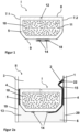
- FIG 1 shows a schematic representation of the spacer I, not according to the invention, comprising a metal base body 5 and a ribbon cable 14 on the outside of the base body 5.
- the metal base body 5 is a hollow body profile comprising two pane contact surfaces 7.1 and 7.2, a glazing interior surface 8, an outer surface 9 and a hollow chamber 10
- the base body 5 consists of aluminum.
- the outer surface 9 has an angled shape, with the portions of the outer surface adjacent to the disk contact surfaces 7.1 and 7.2 being inclined at an angle of 30° to the disk contact surfaces 7.1 and 7.2. This improves the stability of the base body 5.
- the hollow body 10 is filled with a desiccant 11. As a desiccant 11 molecular sieve is used.
- the glazing interior surface 8 of the spacer I has openings 12 which are arranged circumferentially along the glazing interior surface 8 at regular intervals in order to allow gas exchange between the interior of the insulating glazing and the hollow chamber 10 . Any humidity present in the interior is thus absorbed by the desiccant 11 .
- the openings 12 are designed as slits with a width of 0.2 mm and a length of 2 mm.
- the flat ribbon cable 14 is designed as a two-core flat ribbon conductor in the form of a flat laminated cable (FLC) made from two strips of copper foil, surrounded by insulation 18 made from polyethylene terephthalate and attached to the outside 9 of the spacer I.
- FLC flat laminated cable
- the current-carrying wires of the ribbon conductor 14 are surrounded by the insulation 18, which insulates the wires from each other and from the base body 5 and the environment.
- the ribbon cable 14 is attached by means of a hot-melt adhesive, which materially connects the outer surface 9 of the spacer I to the insulation 18 .
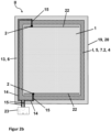
- FIG 2a shows insulating glazing II, not according to the invention, with a spacer I, not according to the invention.
- the sealant 4 connects the pane contact surfaces 7.1 and 7.2 of the spacer I with the panes 19 and 20.
- the glazing interior 3 adjoining the glazing interior surface 8 of the spacer I is defined as the space delimited by the panes 19, 20 and the spacer I.
- the outer space 13 between the panes adjoining the outer surface 9 of the spacer I is a strip-shaped circumferential section of the glazing which is bounded on one side by the two panes 19, 20 and on another side by the spacer I and whose fourth edge is open.
- the glazing interior 3 is filled with argon.
- a sealant 4 is introduced between a respective pane contact surface 7.1 or 7.2 and the adjacent pane 19 or 20, which seals the gap between pane 19, 20 and spacer I.
- the sealant 4 is polyisobutylene.
- An outer seal 6 is fitted on the outer surface 9 in the outer space 13 between the panes and serves to bond the first pane 19 and the second pane 20 .
- the outer seal 6 consists of silicone.
- the outer seal 6 ends flush with the pane edges of the first pane 19 and the second pane 20 .
- the second pane 20 has an electrically switchable functional element 1 on the pane surface facing the glazing interior 3 , which is equipped with a bus bar 22 for making electrical contact with the functional element 1 . With the electrically switchable functional element 1 it is an electrochromic layer.
- spacer I corresponds in figure 1 described. In contrast to this, it is a spacer with a polymeric base body 5.
- the polymeric base body 5 contains styrene-acrylic-nitrile (SAN) and about 35% by weight glass fiber.
- a barrier film (not shown) is applied to the outer surface 9 of the spacer I, which reduces the heat transfer through the polymer base body 5 into the interior of the glazing.
- the barrier film comprises four polymeric layers of polyethylene terephthalate with a thickness of 12 ⁇ m and three metallic layers of aluminum with a thickness of 50 nm. The metallic layers and the polymeric layers are applied alternately, with the two outer layers being formed by polymeric layers .
- the ribbon cable 14 of Figure 2a designed in the form of two copper foil strips as cores without further insulation. Since the outer layer of the barrier film is formed by a polymeric layer and this is non-conductive for the electric current, no insulation of the ribbon cable 14 is necessary.
- the outer seal 6 made of silicone introduced in the outer space between the panes 13 also serves as electrical insulation from the environment.
- the ribbon cable 14 is in cross section according to Figure 2a contacted by an electrical connection cable 15.
- the connection cable 15 is soldered onto a core of the ribbon cable 14 and is thus electrically conductively contacted. Both wires of the ribbon cable have different polarities. Starting from the ribbon cable 14 , the electrical connecting cable 15 is routed along the second pane contact surface 7 .
- the electrical connection cable 15 is contacted there via a contact element 2 with the bus bar 22 .
- the contact element 2 is what is known as a crimp connector, the connection between the electrical connecting cable 15 and the contact element 2 being achieved by squeezing the cable into the crimp connector and the opposite end of the crimp connector being soldered onto the busbar 22 . Due to the routing of the ribbon cable 14 according to the invention in a materially integral manner with the outer surface 9, the outer space 13 between the panes is largely free of lines, so that an unhindered automated filling with the outer seal 6 can take place.
- FIG. 2b shows an overall view of the insulating glazing II according to FIG Figure 2a .
- a running on the outer surface 9 of the spacer I ribbon cable 14 with the busbar 22 of the electrically switchable functional element 1 takes place on two opposite edges of the insulating glazing II, with wires of the ribbon cable 14 from both edges opposite polarity are contacted via an electrical connection cable 15.
- An electrical connection cable 15, as shown in Figure 2a described enters the glazing interior 3 along the second pane contact surface 7.2 and is electrically conductively contacted with the busbar 22 via a contact element 2.
- the spacer I is bent at the corners of the insulating glazing II, so that the ribbon cable 14 on the outside 9 of the spacer I is also continuous at the corners of the glazing.
- Both cores of the ribbon cable 14 are connected in the vicinity of each other to a further electrical connection cable 15 and connected to a voltage source 23 via this.
- the voltage source 23 is a DC voltage source for operating the electrochromic functional element 1 and is located outside the glazing.
- the electrical connecting cables 15 that make contact with one wire of the ribbon conductor 14 are connected to different poles of the voltage source, so that a potential difference arises between the two opposite bus bars 22 .
- the voltage applied to the busbars 22 causes ion migration within the active layer of the electrochromic functional element, as a result of which its transmission is influenced.
- the ribbon cable 14 encompasses the base body 5 along its entire circumference, since a spacer I that was already provided with an integrated ribbon cable 14 was used to produce the spacer frame. For the sake of clarity, in Figure 2a only the sections of the ribbon cable 14 that serve to connect the electrochromic functional element 1 are shown.
- Figure 3a and 3b show a detail of the water- and vapour-tight barrier film 16 on the outside 9 of a polymeric base body 5 of the spacer I according to the invention, with ribbon cables 14 each comprising two cores of copper foil conductors being attached at different points on the barrier film 16.
- the geometry and material composition of the spacer I corresponds to that in Figure 2a described.
- a water- and vapor-tight barrier film is applied, which reduces the heat transfer through the polymer base body 5 into the interior of the glazing.
- the barrier film 16 comprises three polymer layers 16.1 made of polyethylene terephthalate with a thickness of 12 ⁇ m and three metallic layers 16.2 made of aluminum with a thickness of 50 nm.
- the metallic layers 16.2 and the polymer layers 16.1 are each applied alternately, the two outer layers of polymer layers 16.1 are formed.
- the ribbon cable 14 is laminated onto the base body 5 together with the watertight and vapor-tight barrier film 16 ( Figure 3a ).
- the polymeric layer 16.1 adjacent to the base body 5 encloses the ribbon cable 14 and, together with the polymeric base body 5, ensures electrical insulation of the ribbon cable from the environment.
- the barrier film 16 comprises two metallic layers 16.2 attached to both surfaces of a polymeric layer 16.1.
- the ribbon cable 14 is applied to the surface of the barrier film 16 pointing in the direction of the outer space between the panes, insulation 18 being applied between the adjacent metallic layer 16.2 and the ribbon cable 14.
- the insulation 18 is formed by an adhesive layer, here a polyurethane adhesive.
- the adhesive layer is applied to the barrier film 16 and the ribbon cable 14 is introduced into the adhesive layer that has not yet hardened.
- the adhesive layer serves as electrical insulation of the ribbon cable 14 from the underlying metallic layer 16.2.
- FIG 4 shows an embodiment of a triple insulating glazing not according to the invention with a double spacer in cross section.
- the basic structure of the insulating glazing II corresponds to that in Figure 2a and 2 B described.
- the polymer base body 5 has a groove 17 between the first disc contact surface 7.1 and the second disc contact surface 7.2, with a first hollow chamber 10.1 between the groove 17 and the first disc contact surface 7.1 and a second hollow chamber between the groove 17 and the second disc contact surface 7.2 10.2 lies.
- the side flanks of the groove 17 are formed by the walls of the two hollow chambers 10.1 and 10.2, while the bottom surface of the groove 17 borders directly on the outer surface 9.
- the groove 17 runs parallel to the disk contact surfaces 7.
- a third disk 21 is inserted into the groove 17 of the spacer I, which carries an electrically switchable functional element 1, here also an electrochromic functional element, with a bus bar 22 on a disk surface.
- a contact element 2 which is designed as a spring contact.
- the contact element 2 is fitted in the groove 17 before the third disk 21 is inserted.
- an entry opening 25 in the form of a drilled hole. This is produced before the contact element 2 is inserted, so that the contact element 2 can be inserted into it and the contact element protrudes through the base body 5 to the outer surface.
- the third disk 21 is inserted into the groove 17 in such a way that the bus bar 22 points in the direction of the contact element 2 .
- the spring contact is against 21 when inserting the third disc pressed the bus bar 22, whereby the desired electrical contacting comes about.
- the groove 17 also includes an insert 24 which encircles the edge of the third disc 21 and fits flush within the groove 17.
- the insert 24 consists of ethylene-propylene-diene rubber and is cut out in the area of the contact element 2 .
- the insert 24 fixes the third pane 21 free of stress and compensates for thermal expansion of the pane. Furthermore, the insert 24 prevents the development of noise due to the third pane 21 slipping.
- the insulating glazing II according to FIG figure 4 enables electrical contacting of the electrically switchable functional element that is invisible to the observer, the busbar 22 also lying completely inside the groove 17 and being covered by it.
- step IV in the case of double glazing, a first pane 19 or second pane 20 with an electrochromic functional element is attached to a pane contact surface 7 of the spacer I via a sealant 4 .
- the electrochromic functional element is directed in the direction of the later glazing interior 3 .
- step V the second pane 20 is then attached to the pane contact surface 7 that is still available, also using a sealant 4 .
- step IV a third pane 21 is inserted into the groove 17 of the spacer I and in step V the first and second panes 19 and 20 are attached to the pane contact surfaces 7 using a sealant 4.
Claims (13)
- - Espaceur (I) avec câble plat intégré (14) pour vitrages isolants, comportant au moins- un corps de base polymère (5), comportant deux surfaces de contact de vitre (7.1 , 7.2), une surface d'espace intérieur de vitrage (8), une surface extérieure (9) et- au moins un câble plat (14) sur la surface extérieure (9),- le câble plat (14) étant relié par liaison de matière à la surface extérieure (9), intégré au corps de base polymère (5) directement par un film barrière (16) étanche au gaz et à la vapeur dans l'espaceur (I) et le film barrière (16) étanche au gaz et à la vapeur étant appliqué au moins sur la surface extérieure (9) du corps de base polymère (5),- le câble plat (14) s'étendant entre la surface extérieure (9) du corps de base (5) et le film barrière (16) étanche au gaz et à la vapeur ou à l'intérieur du film barrière (16) étanche au gaz et à la vapeur, ou sur la surface du film barrière (16) étanche au gaz et à la vapeur, qui est opposée à la surface extérieure (9) du corps de base (5).
- - Espaceur (I) selon la revendication 1, dans lequel le câble plat (14) est collé, soudé, laminé ou coextrudé à la surface extérieure (9) de l'espaceur (I).
- - Espaceur (I) selon l'une des revendications 1 ou 2, dans lequel le câble plat (14) comporte au moins un brin sous la forme d'une feuille métallique.
- - Espaceur (I) selon l'une des revendications 1 à 3, dans lequel le film barrière (16) étanche au gaz et à l'eau contient une succession en alternance de couches métalliques (16.1) et de couches polymères (16.2).
- - Espaceur (I) selon la revendication 4, dans lequel le câble plat (14) s'étend à l'intérieur du film barrière (16) étanche au gaz et à la vapeur et est de préférence adjacent à deux couches polymères (16.2) ou à une couche polymère (16.2) et au corps de base polymère (5) .
- - Espaceur (I) selon l'une des revendications 1 à 5, dans lequel le câble plat (14) est laminé conjointement avec le film barrière (16) sur le corps de base polymère (5) ou le câble plat (14) est appliqué sur le corps de base polymère (5) par coextrusion du corps de base polymère (5) et du film barrière (16).
- - Espaceur (I) selon l'une des revendications 1 à 6, dans lequel l'espaceur (I) comporte une rainure (17) destinée à recevoir une vitre, qui s'étend parallèlement à la première surface de contact de vitre (7.1) et à la seconde surface de contact de vitre (7.2).
- - Vitrage isolant (II) comportant au moins une première vitre (19) et une seconde vitre (20), un espaceur périphérique (I) entourant les vitres selon l'une des revendications 1 à 7 et un élément fonctionnel (1) commutable électriquement dans l'espace intérieur de vitrage (3)
dans lequel :- la première vitre (19) s'appuie sur la première surface de contact de vitre lequel (7.1) ;- la seconde vitre (20) s'appuie sur la seconde surface de contact de vitre (7.2);- un câble de connexion électrique (15) établit un contact conducteur de l'électricité avec le câble plat (14) ;- le câble de connexion électrique (15) s'étend entre la première vitre (19) et la première surface de contact de vitre (7.1) ou entre la seconde vitre (20) et la seconde surface de contact de vitre (7.2) et pénètre dans l'espace intérieur de vitrage (3) ; et- le câble de connexion électrique (15) établit un contact conducteur de l'électricité avec l'élément fonctionnel (1) commutable électriquement dans l'espace intérieur de vitrage (3). - - Vitrage isolant (II) comportant au moins une première vitre (19), une deuxième vitre (20) et une troisième vitre (21), un espaceur périphérique (I) entourant les vitres selon la revendication 7 et un élément fonctionnel (1) commutable électriquement sur au moins une surface de la troisième vitre (21),
dans lequel :- la première vitre (19) s'appuie sur la première surface de contact de vitre (7.1) ;- la deuxième vitre (20) s'appuie sur la seconde surface de contact de vitre (7.2) ;- la troisième vitre (21) est introduite dans la rainure (17) de l'espaceur (I) ;- un câble de connexion électrique (15) établit un contact conducteur de l'électricité avec le câble plat (14) ; et- le câble de connexion électrique (15) établit un contact conducteur de l'électricité avec l'élément fonctionnel (1) commutable électriquement par l'intermédiaire d'une ouverture d'entrée dans la face de fond de la rainure (17) . - - Vitrage isolant (II) selon l'une des revendications 8 ou 9, dans lequel le câble de connexion électrique (15) établit un contact conducteur de l'électricité avec l'élément fonctionnel (1) commutable électriquement par l'intermédiaire d'un élément de contact (2), de préférence par l'intermédiaire d'un contact à ressort.
- - Procédé de fabrication d'un vitrage isolant (II) selon l'une des revendications 8 à 10, dans lequel au moinsa) un espaceur (I) avec câble plat intégré (14) est mis à disposition ;b) l'espaceur (I) est fixé à l'aide d'un moyen d'étanchéité (4) par l'intermédiaire d'une surface de contact de vitre respective (7.1, 7.2) entre une première vitre (1) et une deuxième vitre (2) et un élément fonctionnel (1) commutable électriquement est introduit dans l'espace intérieur de vitrage (3) ;c) l'agencement est pressé ; etd) un joint d'étanchéité extérieur (6) est introduit dans l'espace entre vitres extérieur (13),le câble plat (14) étant mis en contact conducteur de l'électricité avec l'élément fonctionnel (1) commutable électriquement à l'étape b).
- - Procédé selon la revendication 11, dans lequel, avant l'étape b), une troisième vitre (21) est introduite dans une rainure (17) de l'espaceur (I).
- - Utilisation d'un espaceur (I) selon l'une des revendications 1 à 7 dans des vitrages isolants (II) comportant des éléments fonctionnels (22) commutables électriquement, de préférence comportant un élément fonctionnel SPD, un élément fonctionnel PDLC, un élément fonctionnel électrochrome ou un élément fonctionnel électroluminescent.
Applications Claiming Priority (2)
| Application Number | Priority Date | Filing Date | Title |
|---|---|---|---|
| EP18152708 | 2018-01-22 | ||
| PCT/EP2019/051088 WO2019141749A1 (fr) | 2018-01-22 | 2019-01-17 | Intercalaire pour vitrages isolants, à câble plat intégré |
Publications (2)
| Publication Number | Publication Date |
|---|---|
| EP3743584A1 EP3743584A1 (fr) | 2020-12-02 |
| EP3743584B1 true EP3743584B1 (fr) | 2023-04-05 |
Family
ID=61007630
Family Applications (1)
| Application Number | Title | Priority Date | Filing Date |
|---|---|---|---|
| EP19700600.0A Active EP3743584B1 (fr) | 2018-01-22 | 2019-01-17 | Dispositif d'écartement pour vitrages isolants doté du câble plat intégré |
Country Status (5)
| Country | Link |
|---|---|
| US (1) | US11168514B2 (fr) |
| EP (1) | EP3743584B1 (fr) |
| JP (1) | JP7032552B6 (fr) |
| CN (1) | CN111655960B (fr) |
| WO (1) | WO2019141749A1 (fr) |
Families Citing this family (15)
| Publication number | Priority date | Publication date | Assignee | Title |
|---|---|---|---|---|
| US10303035B2 (en) | 2009-12-22 | 2019-05-28 | View, Inc. | Self-contained EC IGU |
| US11314139B2 (en) | 2009-12-22 | 2022-04-26 | View, Inc. | Self-contained EC IGU |
| US8711465B2 (en) | 2010-12-08 | 2014-04-29 | View, Inc. | Spacers for insulated glass units |
| US8643933B2 (en) | 2011-12-14 | 2014-02-04 | View, Inc. | Connectors for smart windows |
| US10180606B2 (en) | 2010-12-08 | 2019-01-15 | View, Inc. | Connectors for smart windows |
| US10175549B2 (en) | 2011-03-16 | 2019-01-08 | View, Inc. | Connectors for smart windows |
| US11719039B2 (en) | 2011-12-14 | 2023-08-08 | View, Inc. | Connectors for smart windows |
| US11255120B2 (en) | 2012-05-25 | 2022-02-22 | View, Inc. | Tester and electrical connectors for insulated glass units |
| US10288971B2 (en) | 2012-08-23 | 2019-05-14 | View, Inc. | Photonic-powered EC devices |
| US10975612B2 (en) | 2014-12-15 | 2021-04-13 | View, Inc. | Seals for electrochromic windows |
| PL3477035T3 (pl) * | 2017-10-30 | 2020-12-28 | Technoform Glass Insulation Holding Gmbh | Element dystansowy do zastosowań fotowoltaicznych |
| RU2751326C1 (ru) * | 2018-01-22 | 2021-07-13 | Сэн-Гобэн Гласс Франс | Изоляционное остекление, окно и способ изготовления |
| EP3818232B1 (fr) | 2018-07-04 | 2022-12-28 | Saint-Gobain Glass France | Élément de recouvrement pour barres de raccordement |
| CN114981076A (zh) * | 2020-01-28 | 2022-08-30 | 法国圣戈班玻璃厂 | 包括中断的粘附层的间隔件 |
| GB202207366D0 (en) | 2022-05-19 | 2022-07-06 | Pilkington Group Ltd | Laminated pane comprising an electrical element |
Family Cites Families (28)
| Publication number | Priority date | Publication date | Assignee | Title |
|---|---|---|---|---|
| DE3330305A1 (de) | 1983-08-23 | 1985-03-14 | Rainer 6072 Dreieich Bauer | Fenster |
| US5773135A (en) | 1991-04-22 | 1998-06-30 | Lafond; Luc | Insulated assembly incorporating a thermoplastic barrier member |
| DE4235063A1 (de) | 1992-10-17 | 1994-04-21 | Ver Glaswerke Gmbh | Autoglasscheibe aus Verbundglas mit in der Zwischenschicht eingebetteten Drähten und einem Anschlußkabel |
| DE9313394U1 (de) | 1992-10-17 | 1993-10-28 | Ver Glaswerke Gmbh | Autoglasscheibe aus Verbundglas mit in der Zwischenschicht eingebetteten Drähten und einem Anschlußkabel |
| DE19544127C1 (de) | 1995-11-27 | 1997-03-20 | Gimsa Jan Dr | Verfahren und Vorrichtung zur Erzeugung von Resonanzerscheinungen in Partikelsuspensionen und ihre Verwendung |
| SI0852280T2 (sl) | 1996-12-20 | 2009-12-31 | Saint Gobain | Distančnik za izdelavo izolacijskega sklopa šip |
| TWI260945B (en) | 2003-05-16 | 2006-08-21 | Toyota Ind Corp | Light-emitting apparatus and method for forming the same |
| DE10361184B3 (de) | 2003-12-24 | 2005-02-03 | Glaswerke Arnold Gmbh & Co. Kg | Photovoltaik-Isolierglasscheibe |
| DE202004019286U1 (de) | 2004-12-14 | 2006-04-20 | Saint-Gobain Sekurit Deutschland Gmbh & Co. Kg | Flachleiter-Anschlusselement für Fensterscheiben |
| FR2901891B1 (fr) | 2006-05-30 | 2008-09-26 | Schefenacker Vision Systems Fr | Cellule electrochrome, son utilisation dans la realisation d'une vitre ou d'un retroviseur et son procede de realisation. |
| DE102008026339A1 (de) | 2008-05-31 | 2009-12-03 | Saint-Gobain Sekurit Deutschland Gmbh & Co. Kg | Elektrisch schaltbares Sichtschutzfenster |
| FR2944148B1 (fr) | 2009-04-02 | 2012-03-02 | Saint Gobain | Procede de fabrication d'une structure a surface texturee pour dispositif a diode electroluminescente organique et structure a surface texturee obtenue par ce procede |
| PT104635A (pt) | 2009-06-16 | 2010-12-16 | Univ Nova De Lisboa | Dispositivo electrocrómico e método para a sua produção |
| GB0916379D0 (en) | 2009-09-18 | 2009-10-28 | Pilkington Group Ltd | Laminated glazing |
| FR2962818B1 (fr) | 2010-07-13 | 2013-03-08 | Saint Gobain | Dispositif electrochimique a proprietes de transmission optique et/ou energetique electrocommandables. |
| US8270059B2 (en) | 2010-08-05 | 2012-09-18 | Soladigm, Inc. | Multi-pane electrochromic windows |
| US8164818B2 (en) | 2010-11-08 | 2012-04-24 | Soladigm, Inc. | Electrochromic window fabrication methods |
| US9442339B2 (en) | 2010-12-08 | 2016-09-13 | View, Inc. | Spacers and connectors for insulated glass units |
| EA027387B1 (ru) | 2012-01-13 | 2017-07-31 | Сэн-Гобэн Гласс Франс | Дистанционная рамка для изоляционных стеклопакетов |
| US9281672B2 (en) | 2012-01-20 | 2016-03-08 | Sage Electrochromics, Inc. | Electrical connectivity within architectural glazing frame systems |
| JP6234560B2 (ja) | 2013-06-14 | 2017-11-22 | サン−ゴバン グラス フランスSaint−Gobain Glass France | 3重断熱ガラス用のスペーサ |
| US10301868B2 (en) * | 2014-06-27 | 2019-05-28 | Saint-Gobain Glass France | Insulated glazing comprising a spacer, and production method |
| KR102056036B1 (ko) | 2014-09-25 | 2019-12-13 | 쌩-고벵 글래스 프랑스 | 단열 글레이징 유닛용 스페이서 |
| JP6395938B2 (ja) | 2014-12-08 | 2018-09-26 | サン−ゴバン グラス フランスSaint−Gobain Glass France | 複層ガラス用のスペーサ |
| DE102014119720A1 (de) | 2014-12-30 | 2016-06-30 | Lisa Dräxlmaier GmbH | Isolierter Flachleiter und Flachleiterverbund |
| JP2016141573A (ja) | 2015-01-29 | 2016-08-08 | パナソニックIpマネジメント株式会社 | 複層ガラス及び光学デバイス |
| WO2017106458A1 (fr) | 2015-12-15 | 2017-06-22 | Sage Electrochromics, Inc. | Vitrage isolé et traversées électriques |
| CN206693883U (zh) | 2016-12-28 | 2017-12-01 | 成都中建材光电材料有限公司 | 一种太阳能低辐射可变色玻璃窗、设有其玻璃窗的汽车 |
-
2019
- 2019-01-17 EP EP19700600.0A patent/EP3743584B1/fr active Active
- 2019-01-17 CN CN201980009696.5A patent/CN111655960B/zh active Active
- 2019-01-17 WO PCT/EP2019/051088 patent/WO2019141749A1/fr unknown
- 2019-01-17 US US16/963,717 patent/US11168514B2/en active Active
- 2019-01-17 JP JP2020540577A patent/JP7032552B6/ja active Active
Also Published As
| Publication number | Publication date |
|---|---|
| CN111655960A (zh) | 2020-09-11 |
| EP3743584A1 (fr) | 2020-12-02 |
| JP7032552B2 (ja) | 2022-03-08 |
| WO2019141749A1 (fr) | 2019-07-25 |
| CN111655960B (zh) | 2022-12-20 |
| US11168514B2 (en) | 2021-11-09 |
| JP7032552B6 (ja) | 2022-03-22 |
| US20210079715A1 (en) | 2021-03-18 |
| JP2021513014A (ja) | 2021-05-20 |
Similar Documents
| Publication | Publication Date | Title |
|---|---|---|
| EP3743584B1 (fr) | Dispositif d'écartement pour vitrages isolants doté du câble plat intégré | |
| EP3743583B1 (fr) | Dispositif d'écartement pour vitrages isolants doté d'une conduite d'alimentation électrique intégrée dans une chambre creuse | |
| EP3803017B1 (fr) | Raccord d'angle pour vitrages isolants au câble d'alimentation électrique | |
| EP3818232B1 (fr) | Élément de recouvrement pour barres de raccordement | |
| EP2879869B1 (fr) | Plaque de verre feuilletée avec mise en contact électrique | |
| EP3676661B1 (fr) | Vitrage isolant doté d'un élément de raccordement électrique | |
| EP3877619A1 (fr) | Vitrage isolant à double intercalaire | |
| EP2721238B1 (fr) | Vitrage isolant pourvu d'un élément de raccordement électrique | |
| EP3815462A1 (fr) | Disque comprenant un élément de raccordement électrique et un câble de raccordement | |
| EP1049958A1 (fr) | Cellule electrochrome | |
| EP3702572A1 (fr) | Vitrage isolant pourvu d'élément fonctionnel électrochrome et de revêtement réfléchissant les rayons infrarouges | |
| EP4101030B1 (fr) | Élément de connexion pour un conducteur plat | |
| EP4100251B1 (fr) | Câble plat souple | |
| EP4106992B1 (fr) | Vitre composite pourvue d'une pluralité d'éléments fonctionnels et barre omnibus sur une feuille barrière | |
| WO2019141532A1 (fr) | Vitrage isolant et fenêtre | |
| EP4298306A1 (fr) | Élément de connexion pour vitrages isolants, comprenant un revêtement électroconducteur et/ou un élément fonctionnel pouvant être commandé électriquement | |
| WO2024012876A1 (fr) | Connexion de ligne électrique pour établir un contact électrique | |
| WO2024012877A1 (fr) | Connexion de ligne électrique pour établir un contact électrique | |
| WO2024017641A1 (fr) | Agencement de connexion avec élément de connexion à conducteur plat, et connexion de circuit électrique | |
| WO2024002685A1 (fr) | Câble plat, ligne de connexion électrique, substrat et vitre composite | |
| EP4217576A1 (fr) | Unité de vitrage isolant doté d'un revêtement électroconducteur et/ou d'un élément fonctionnel à commande électrique | |
| EP4222817A1 (fr) | Connexion de ligne électrique pour réaliser un contact électrique avec une électrode de surface | |
| WO2022058109A1 (fr) | Vitre pourvue d'un élément fonctionnel ayant des propriétés optiques réglables électriquement et modèle pour transmission haute fréquence | |
| EP4288832A1 (fr) | Procédé de fabrication d'un dispositif électrochromique, dispositif électrochromique et vitrage isolant | |
| EP3702571A1 (fr) | Vitrage isolant pourvu de revêtement électroconducteur et / ou d'élément fonctionnel électroconducteur |
Legal Events
| Date | Code | Title | Description |
|---|---|---|---|
| STAA | Information on the status of an ep patent application or granted ep patent |
Free format text: STATUS: UNKNOWN |
|
| STAA | Information on the status of an ep patent application or granted ep patent |
Free format text: STATUS: THE INTERNATIONAL PUBLICATION HAS BEEN MADE |
|
| PUAI | Public reference made under article 153(3) epc to a published international application that has entered the european phase |
Free format text: ORIGINAL CODE: 0009012 |
|
| STAA | Information on the status of an ep patent application or granted ep patent |
Free format text: STATUS: REQUEST FOR EXAMINATION WAS MADE |
|
| 17P | Request for examination filed |
Effective date: 20200629 |
|
| AK | Designated contracting states |
Kind code of ref document: A1 Designated state(s): AL AT BE BG CH CY CZ DE DK EE ES FI FR GB GR HR HU IE IS IT LI LT LU LV MC MK MT NL NO PL PT RO RS SE SI SK SM TR |
|
| AX | Request for extension of the european patent |
Extension state: BA ME |
|
| DAV | Request for validation of the european patent (deleted) | ||
| DAX | Request for extension of the european patent (deleted) | ||
| STAA | Information on the status of an ep patent application or granted ep patent |
Free format text: STATUS: EXAMINATION IS IN PROGRESS |
|
| 17Q | First examination report despatched |
Effective date: 20210820 |
|
| GRAP | Despatch of communication of intention to grant a patent |
Free format text: ORIGINAL CODE: EPIDOSNIGR1 |
|
| STAA | Information on the status of an ep patent application or granted ep patent |
Free format text: STATUS: GRANT OF PATENT IS INTENDED |
|
| INTG | Intention to grant announced |
Effective date: 20220719 |
|
| GRAJ | Information related to disapproval of communication of intention to grant by the applicant or resumption of examination proceedings by the epo deleted |
Free format text: ORIGINAL CODE: EPIDOSDIGR1 |
|
| STAA | Information on the status of an ep patent application or granted ep patent |
Free format text: STATUS: EXAMINATION IS IN PROGRESS |
|
| GRAP | Despatch of communication of intention to grant a patent |
Free format text: ORIGINAL CODE: EPIDOSNIGR1 |
|
| INTC | Intention to grant announced (deleted) | ||
| STAA | Information on the status of an ep patent application or granted ep patent |
Free format text: STATUS: GRANT OF PATENT IS INTENDED |
|
| INTG | Intention to grant announced |
Effective date: 20221222 |
|
| RIN1 | Information on inventor provided before grant (corrected) |
Inventor name: MORVAN, GUENAEL Inventor name: KUSTER, HANS-WERNER Inventor name: MARJAN, CHRISTOPHER Inventor name: NEANDER, MARCUS |
|
| GRAS | Grant fee paid |
Free format text: ORIGINAL CODE: EPIDOSNIGR3 |
|
| GRAA | (expected) grant |
Free format text: ORIGINAL CODE: 0009210 |
|
| STAA | Information on the status of an ep patent application or granted ep patent |
Free format text: STATUS: THE PATENT HAS BEEN GRANTED |
|
| AK | Designated contracting states |
Kind code of ref document: B1 Designated state(s): AL AT BE BG CH CY CZ DE DK EE ES FI FR GB GR HR HU IE IS IT LI LT LU LV MC MK MT NL NO PL PT RO RS SE SI SK SM TR |
|
| REG | Reference to a national code |
Ref country code: GB Ref legal event code: FG4D Free format text: NOT ENGLISH |
|
| REG | Reference to a national code |
Ref country code: CH Ref legal event code: EP |
|
| REG | Reference to a national code |
Ref country code: AT Ref legal event code: REF Ref document number: 1558375 Country of ref document: AT Kind code of ref document: T Effective date: 20230415 |
|
| REG | Reference to a national code |
Ref country code: DE Ref legal event code: R096 Ref document number: 502019007391 Country of ref document: DE |
|
| REG | Reference to a national code |
Ref country code: IE Ref legal event code: FG4D Free format text: LANGUAGE OF EP DOCUMENT: GERMAN |
|
| REG | Reference to a national code |
Ref country code: NL Ref legal event code: FP |
|
| P01 | Opt-out of the competence of the unified patent court (upc) registered |
Effective date: 20230515 |
|
| REG | Reference to a national code |
Ref country code: LT Ref legal event code: MG9D |
|
| PG25 | Lapsed in a contracting state [announced via postgrant information from national office to epo] |
Ref country code: SE Free format text: LAPSE BECAUSE OF FAILURE TO SUBMIT A TRANSLATION OF THE DESCRIPTION OR TO PAY THE FEE WITHIN THE PRESCRIBED TIME-LIMIT Effective date: 20230405 Ref country code: PT Free format text: LAPSE BECAUSE OF FAILURE TO SUBMIT A TRANSLATION OF THE DESCRIPTION OR TO PAY THE FEE WITHIN THE PRESCRIBED TIME-LIMIT Effective date: 20230807 Ref country code: NO Free format text: LAPSE BECAUSE OF FAILURE TO SUBMIT A TRANSLATION OF THE DESCRIPTION OR TO PAY THE FEE WITHIN THE PRESCRIBED TIME-LIMIT Effective date: 20230705 Ref country code: ES Free format text: LAPSE BECAUSE OF FAILURE TO SUBMIT A TRANSLATION OF THE DESCRIPTION OR TO PAY THE FEE WITHIN THE PRESCRIBED TIME-LIMIT Effective date: 20230405 |
|
| PG25 | Lapsed in a contracting state [announced via postgrant information from national office to epo] |
Ref country code: RS Free format text: LAPSE BECAUSE OF FAILURE TO SUBMIT A TRANSLATION OF THE DESCRIPTION OR TO PAY THE FEE WITHIN THE PRESCRIBED TIME-LIMIT Effective date: 20230405 Ref country code: PL Free format text: LAPSE BECAUSE OF FAILURE TO SUBMIT A TRANSLATION OF THE DESCRIPTION OR TO PAY THE FEE WITHIN THE PRESCRIBED TIME-LIMIT Effective date: 20230405 Ref country code: LV Free format text: LAPSE BECAUSE OF FAILURE TO SUBMIT A TRANSLATION OF THE DESCRIPTION OR TO PAY THE FEE WITHIN THE PRESCRIBED TIME-LIMIT Effective date: 20230405 Ref country code: LT Free format text: LAPSE BECAUSE OF FAILURE TO SUBMIT A TRANSLATION OF THE DESCRIPTION OR TO PAY THE FEE WITHIN THE PRESCRIBED TIME-LIMIT Effective date: 20230405 Ref country code: IS Free format text: LAPSE BECAUSE OF FAILURE TO SUBMIT A TRANSLATION OF THE DESCRIPTION OR TO PAY THE FEE WITHIN THE PRESCRIBED TIME-LIMIT Effective date: 20230805 Ref country code: HR Free format text: LAPSE BECAUSE OF FAILURE TO SUBMIT A TRANSLATION OF THE DESCRIPTION OR TO PAY THE FEE WITHIN THE PRESCRIBED TIME-LIMIT Effective date: 20230405 Ref country code: GR Free format text: LAPSE BECAUSE OF FAILURE TO SUBMIT A TRANSLATION OF THE DESCRIPTION OR TO PAY THE FEE WITHIN THE PRESCRIBED TIME-LIMIT Effective date: 20230706 |
|
| PG25 | Lapsed in a contracting state [announced via postgrant information from national office to epo] |
Ref country code: FI Free format text: LAPSE BECAUSE OF FAILURE TO SUBMIT A TRANSLATION OF THE DESCRIPTION OR TO PAY THE FEE WITHIN THE PRESCRIBED TIME-LIMIT Effective date: 20230405 |
|
| REG | Reference to a national code |
Ref country code: DE Ref legal event code: R097 Ref document number: 502019007391 Country of ref document: DE |
|
| PG25 | Lapsed in a contracting state [announced via postgrant information from national office to epo] |
Ref country code: SK Free format text: LAPSE BECAUSE OF FAILURE TO SUBMIT A TRANSLATION OF THE DESCRIPTION OR TO PAY THE FEE WITHIN THE PRESCRIBED TIME-LIMIT Effective date: 20230405 |
|
| PG25 | Lapsed in a contracting state [announced via postgrant information from national office to epo] |
Ref country code: SM Free format text: LAPSE BECAUSE OF FAILURE TO SUBMIT A TRANSLATION OF THE DESCRIPTION OR TO PAY THE FEE WITHIN THE PRESCRIBED TIME-LIMIT Effective date: 20230405 Ref country code: SK Free format text: LAPSE BECAUSE OF FAILURE TO SUBMIT A TRANSLATION OF THE DESCRIPTION OR TO PAY THE FEE WITHIN THE PRESCRIBED TIME-LIMIT Effective date: 20230405 Ref country code: RO Free format text: LAPSE BECAUSE OF FAILURE TO SUBMIT A TRANSLATION OF THE DESCRIPTION OR TO PAY THE FEE WITHIN THE PRESCRIBED TIME-LIMIT Effective date: 20230405 Ref country code: EE Free format text: LAPSE BECAUSE OF FAILURE TO SUBMIT A TRANSLATION OF THE DESCRIPTION OR TO PAY THE FEE WITHIN THE PRESCRIBED TIME-LIMIT Effective date: 20230405 Ref country code: DK Free format text: LAPSE BECAUSE OF FAILURE TO SUBMIT A TRANSLATION OF THE DESCRIPTION OR TO PAY THE FEE WITHIN THE PRESCRIBED TIME-LIMIT Effective date: 20230405 Ref country code: CZ Free format text: LAPSE BECAUSE OF FAILURE TO SUBMIT A TRANSLATION OF THE DESCRIPTION OR TO PAY THE FEE WITHIN THE PRESCRIBED TIME-LIMIT Effective date: 20230405 |
|
| PGFP | Annual fee paid to national office [announced via postgrant information from national office to epo] |
Ref country code: NL Payment date: 20231215 Year of fee payment: 6 Ref country code: FR Payment date: 20231212 Year of fee payment: 6 |
|
| PLBE | No opposition filed within time limit |
Free format text: ORIGINAL CODE: 0009261 |
|
| STAA | Information on the status of an ep patent application or granted ep patent |
Free format text: STATUS: NO OPPOSITION FILED WITHIN TIME LIMIT |
|
| PGFP | Annual fee paid to national office [announced via postgrant information from national office to epo] |
Ref country code: BE Payment date: 20231219 Year of fee payment: 6 |
|
| 26N | No opposition filed |
Effective date: 20240108 |
|
| PGFP | Annual fee paid to national office [announced via postgrant information from national office to epo] |
Ref country code: DE Payment date: 20231205 Year of fee payment: 6 Ref country code: CH Payment date: 20240202 Year of fee payment: 6 |
|
| PG25 | Lapsed in a contracting state [announced via postgrant information from national office to epo] |
Ref country code: SI Free format text: LAPSE BECAUSE OF FAILURE TO SUBMIT A TRANSLATION OF THE DESCRIPTION OR TO PAY THE FEE WITHIN THE PRESCRIBED TIME-LIMIT Effective date: 20230405 |