EP3743584B1 - Spacer for insulated glazing units with integrated flat wire - Google Patents
Spacer for insulated glazing units with integrated flat wire Download PDFInfo
- Publication number
- EP3743584B1 EP3743584B1 EP19700600.0A EP19700600A EP3743584B1 EP 3743584 B1 EP3743584 B1 EP 3743584B1 EP 19700600 A EP19700600 A EP 19700600A EP 3743584 B1 EP3743584 B1 EP 3743584B1
- Authority
- EP
- European Patent Office
- Prior art keywords
- pane
- spacer
- glazing
- ribbon cable
- cable
- Prior art date
- Legal status (The legal status is an assumption and is not a legal conclusion. Google has not performed a legal analysis and makes no representation as to the accuracy of the status listed.)
- Active
Links
- 125000006850 spacer group Chemical group 0.000 title claims description 170
- 239000010410 layer Substances 0.000 claims description 93
- 230000004888 barrier function Effects 0.000 claims description 64
- 239000000565 sealant Substances 0.000 claims description 28
- 229910052751 metal Inorganic materials 0.000 claims description 24
- 239000002184 metal Substances 0.000 claims description 24
- 239000011888 foil Substances 0.000 claims description 21
- 238000000034 method Methods 0.000 claims description 17
- 238000004519 manufacturing process Methods 0.000 claims description 10
- 239000013047 polymeric layer Substances 0.000 claims description 10
- 239000004983 Polymer Dispersed Liquid Crystal Substances 0.000 claims description 4
- 239000010408 film Substances 0.000 description 55
- 239000004020 conductor Substances 0.000 description 52
- 229920000642 polymer Polymers 0.000 description 37
- 238000009413 insulation Methods 0.000 description 30
- -1 polyethylene Polymers 0.000 description 15
- 239000007789 gas Substances 0.000 description 14
- 239000000853 adhesive Substances 0.000 description 13
- 230000001070 adhesive effect Effects 0.000 description 13
- RYGMFSIKBFXOCR-UHFFFAOYSA-N Copper Chemical compound [Cu] RYGMFSIKBFXOCR-UHFFFAOYSA-N 0.000 description 11
- 238000013461 design Methods 0.000 description 11
- 239000002274 desiccant Substances 0.000 description 10
- 239000011521 glass Substances 0.000 description 10
- 239000000463 material Substances 0.000 description 9
- 230000005540 biological transmission Effects 0.000 description 8
- 239000000203 mixture Substances 0.000 description 8
- 229910052782 aluminium Inorganic materials 0.000 description 7
- XAGFODPZIPBFFR-UHFFFAOYSA-N aluminium Chemical compound [Al] XAGFODPZIPBFFR-UHFFFAOYSA-N 0.000 description 7
- 239000000919 ceramic Substances 0.000 description 7
- 238000009434 installation Methods 0.000 description 7
- 229920003023 plastic Polymers 0.000 description 7
- 239000004033 plastic Substances 0.000 description 7
- 229920000139 polyethylene terephthalate Polymers 0.000 description 7
- 239000005020 polyethylene terephthalate Substances 0.000 description 7
- 239000004698 Polyethylene Substances 0.000 description 6
- 238000000576 coating method Methods 0.000 description 6
- 239000011889 copper foil Substances 0.000 description 6
- 238000010292 electrical insulation Methods 0.000 description 6
- 239000003365 glass fiber Substances 0.000 description 6
- 230000003287 optical effect Effects 0.000 description 6
- 229920000573 polyethylene Polymers 0.000 description 6
- 238000003466 welding Methods 0.000 description 6
- 229920002367 Polyisobutene Polymers 0.000 description 5
- 230000008901 benefit Effects 0.000 description 5
- 229920001577 copolymer Polymers 0.000 description 5
- 229910052802 copper Inorganic materials 0.000 description 5
- 239000010949 copper Substances 0.000 description 5
- 150000002500 ions Chemical class 0.000 description 5
- 239000002245 particle Substances 0.000 description 5
- 239000004417 polycarbonate Substances 0.000 description 5
- 229920000515 polycarbonate Polymers 0.000 description 5
- 229920001296 polysiloxane Polymers 0.000 description 5
- 229920002635 polyurethane Polymers 0.000 description 5
- 239000004814 polyurethane Substances 0.000 description 5
- XKRFYHLGVUSROY-UHFFFAOYSA-N Argon Chemical compound [Ar] XKRFYHLGVUSROY-UHFFFAOYSA-N 0.000 description 4
- 239000004743 Polypropylene Substances 0.000 description 4
- 238000004026 adhesive bonding Methods 0.000 description 4
- 239000012790 adhesive layer Substances 0.000 description 4
- 239000011248 coating agent Substances 0.000 description 4
- 238000011049 filling Methods 0.000 description 4
- 239000004973 liquid crystal related substance Substances 0.000 description 4
- 229920001155 polypropylene Polymers 0.000 description 4
- 238000012545 processing Methods 0.000 description 4
- 238000007789 sealing Methods 0.000 description 4
- 239000004945 silicone rubber Substances 0.000 description 4
- 238000012546 transfer Methods 0.000 description 4
- XEEYBQQBJWHFJM-UHFFFAOYSA-N Iron Chemical compound [Fe] XEEYBQQBJWHFJM-UHFFFAOYSA-N 0.000 description 3
- BQCADISMDOOEFD-UHFFFAOYSA-N Silver Chemical compound [Ag] BQCADISMDOOEFD-UHFFFAOYSA-N 0.000 description 3
- 239000011324 bead Substances 0.000 description 3
- 230000007547 defect Effects 0.000 description 3
- 230000036961 partial effect Effects 0.000 description 3
- 229920000058 polyacrylate Polymers 0.000 description 3
- 229920001707 polybutylene terephthalate Polymers 0.000 description 3
- 229920000728 polyester Polymers 0.000 description 3
- 230000008569 process Effects 0.000 description 3
- 230000002829 reductive effect Effects 0.000 description 3
- 229920002379 silicone rubber Polymers 0.000 description 3
- 229910052709 silver Inorganic materials 0.000 description 3
- 239000004332 silver Substances 0.000 description 3
- 238000005476 soldering Methods 0.000 description 3
- XLYOFNOQVPJJNP-UHFFFAOYSA-N water Substances O XLYOFNOQVPJJNP-UHFFFAOYSA-N 0.000 description 3
- 239000004952 Polyamide Substances 0.000 description 2
- 238000010521 absorption reaction Methods 0.000 description 2
- 239000004676 acrylonitrile butadiene styrene Substances 0.000 description 2
- 229910045601 alloy Inorganic materials 0.000 description 2
- 239000000956 alloy Substances 0.000 description 2
- 229910052786 argon Inorganic materials 0.000 description 2
- 229920005549 butyl rubber Polymers 0.000 description 2
- QXJJQWWVWRCVQT-UHFFFAOYSA-K calcium;sodium;phosphate Chemical compound [Na+].[Ca+2].[O-]P([O-])([O-])=O QXJJQWWVWRCVQT-UHFFFAOYSA-K 0.000 description 2
- 150000001875 compounds Chemical class 0.000 description 2
- 238000004132 cross linking Methods 0.000 description 2
- 238000001125 extrusion Methods 0.000 description 2
- 239000005329 float glass Substances 0.000 description 2
- PCHJSUWPFVWCPO-UHFFFAOYSA-N gold Chemical compound [Au] PCHJSUWPFVWCPO-UHFFFAOYSA-N 0.000 description 2
- 229910052737 gold Inorganic materials 0.000 description 2
- 239000010931 gold Substances 0.000 description 2
- 239000011261 inert gas Substances 0.000 description 2
- 229910052742 iron Inorganic materials 0.000 description 2
- 238000010030 laminating Methods 0.000 description 2
- 238000003475 lamination Methods 0.000 description 2
- 239000011159 matrix material Substances 0.000 description 2
- 238000005240 physical vapour deposition Methods 0.000 description 2
- 239000002985 plastic film Substances 0.000 description 2
- 229920006255 plastic film Polymers 0.000 description 2
- 229920002647 polyamide Polymers 0.000 description 2
- 238000009417 prefabrication Methods 0.000 description 2
- 238000003825 pressing Methods 0.000 description 2
- 239000005336 safety glass Substances 0.000 description 2
- 239000003566 sealing material Substances 0.000 description 2
- LIVNPJMFVYWSIS-UHFFFAOYSA-N silicon monoxide Chemical class [Si-]#[O+] LIVNPJMFVYWSIS-UHFFFAOYSA-N 0.000 description 2
- 229910052814 silicon oxide Inorganic materials 0.000 description 2
- 229920001169 thermoplastic Polymers 0.000 description 2
- 239000004416 thermosoftening plastic Substances 0.000 description 2
- 229920006942 ABS/PC Polymers 0.000 description 1
- PNEYBMLMFCGWSK-UHFFFAOYSA-N Alumina Chemical class [O-2].[O-2].[O-2].[Al+3].[Al+3] PNEYBMLMFCGWSK-UHFFFAOYSA-N 0.000 description 1
- VYZAMTAEIAYCRO-UHFFFAOYSA-N Chromium Chemical compound [Cr] VYZAMTAEIAYCRO-UHFFFAOYSA-N 0.000 description 1
- 229910000881 Cu alloy Inorganic materials 0.000 description 1
- 229920002943 EPDM rubber Polymers 0.000 description 1
- IMROMDMJAWUWLK-UHFFFAOYSA-N Ethenol Chemical compound OC=C IMROMDMJAWUWLK-UHFFFAOYSA-N 0.000 description 1
- 229920000219 Ethylene vinyl alcohol Polymers 0.000 description 1
- 239000004831 Hot glue Substances 0.000 description 1
- 229920002319 Poly(methyl acrylate) Polymers 0.000 description 1
- 239000005062 Polybutadiene Substances 0.000 description 1
- 239000004642 Polyimide Substances 0.000 description 1
- 239000004721 Polyphenylene oxide Substances 0.000 description 1
- 239000004793 Polystyrene Substances 0.000 description 1
- 229920001328 Polyvinylidene chloride Polymers 0.000 description 1
- VYPSYNLAJGMNEJ-UHFFFAOYSA-N Silicium dioxide Chemical compound O=[Si]=O VYPSYNLAJGMNEJ-UHFFFAOYSA-N 0.000 description 1
- ATJFFYVFTNAWJD-UHFFFAOYSA-N Tin Chemical compound [Sn] ATJFFYVFTNAWJD-UHFFFAOYSA-N 0.000 description 1
- XHCLAFWTIXFWPH-UHFFFAOYSA-N [O-2].[O-2].[O-2].[O-2].[O-2].[V+5].[V+5] Chemical compound [O-2].[O-2].[O-2].[O-2].[O-2].[V+5].[V+5] XHCLAFWTIXFWPH-UHFFFAOYSA-N 0.000 description 1
- XECAHXYUAAWDEL-UHFFFAOYSA-N acrylonitrile butadiene styrene Chemical compound C=CC=C.C=CC#N.C=CC1=CC=CC=C1 XECAHXYUAAWDEL-UHFFFAOYSA-N 0.000 description 1
- 229920000122 acrylonitrile butadiene styrene Polymers 0.000 description 1
- 150000008360 acrylonitriles Chemical class 0.000 description 1
- 238000004378 air conditioning Methods 0.000 description 1
- 230000033228 biological regulation Effects 0.000 description 1
- 239000005388 borosilicate glass Substances 0.000 description 1
- 238000009435 building construction Methods 0.000 description 1
- DQXBYHZEEUGOBF-UHFFFAOYSA-N but-3-enoic acid;ethene Chemical compound C=C.OC(=O)CC=C DQXBYHZEEUGOBF-UHFFFAOYSA-N 0.000 description 1
- 230000008859 change Effects 0.000 description 1
- 229910052804 chromium Inorganic materials 0.000 description 1
- 239000011651 chromium Substances 0.000 description 1
- 230000001419 dependent effect Effects 0.000 description 1
- 238000000151 deposition Methods 0.000 description 1
- 238000011161 development Methods 0.000 description 1
- 238000009826 distribution Methods 0.000 description 1
- 230000009977 dual effect Effects 0.000 description 1
- 229920001971 elastomer Polymers 0.000 description 1
- 238000004870 electrical engineering Methods 0.000 description 1
- 238000005265 energy consumption Methods 0.000 description 1
- 230000007613 environmental effect Effects 0.000 description 1
- 239000005038 ethylene vinyl acetate Substances 0.000 description 1
- 239000004715 ethylene vinyl alcohol Substances 0.000 description 1
- 238000009422 external insulation Methods 0.000 description 1
- 238000000227 grinding Methods 0.000 description 1
- 238000009499 grossing Methods 0.000 description 1
- 238000010438 heat treatment Methods 0.000 description 1
- RZXDTJIXPSCHCI-UHFFFAOYSA-N hexa-1,5-diene-2,5-diol Chemical compound OC(=C)CCC(O)=C RZXDTJIXPSCHCI-UHFFFAOYSA-N 0.000 description 1
- 230000006872 improvement Effects 0.000 description 1
- 238000010348 incorporation Methods 0.000 description 1
- 230000010354 integration Effects 0.000 description 1
- 238000002955 isolation Methods 0.000 description 1
- 229910052743 krypton Inorganic materials 0.000 description 1
- DNNSSWSSYDEUBZ-UHFFFAOYSA-N krypton atom Chemical compound [Kr] DNNSSWSSYDEUBZ-UHFFFAOYSA-N 0.000 description 1
- 230000031700 light absorption Effects 0.000 description 1
- 238000004020 luminiscence type Methods 0.000 description 1
- 238000010297 mechanical methods and process Methods 0.000 description 1
- 230000005226 mechanical processes and functions Effects 0.000 description 1
- 229910001092 metal group alloy Inorganic materials 0.000 description 1
- 150000002739 metals Chemical class 0.000 description 1
- 230000005012 migration Effects 0.000 description 1
- 238000013508 migration Methods 0.000 description 1
- 238000003801 milling Methods 0.000 description 1
- 238000012986 modification Methods 0.000 description 1
- 230000004048 modification Effects 0.000 description 1
- 239000002808 molecular sieve Substances 0.000 description 1
- 125000005487 naphthalate group Chemical group 0.000 description 1
- QGLKJKCYBOYXKC-UHFFFAOYSA-N nonaoxidotritungsten Chemical compound O=[W]1(=O)O[W](=O)(=O)O[W](=O)(=O)O1 QGLKJKCYBOYXKC-UHFFFAOYSA-N 0.000 description 1
- 230000000414 obstructive effect Effects 0.000 description 1
- 238000005457 optimization Methods 0.000 description 1
- 150000008116 organic polysulfides Chemical class 0.000 description 1
- 230000000149 penetrating effect Effects 0.000 description 1
- 230000035515 penetration Effects 0.000 description 1
- 229920001200 poly(ethylene-vinyl acetate) Polymers 0.000 description 1
- 229920003229 poly(methyl methacrylate) Polymers 0.000 description 1
- 229920002857 polybutadiene Polymers 0.000 description 1
- 229920000570 polyether Polymers 0.000 description 1
- 229920001721 polyimide Polymers 0.000 description 1
- 239000004926 polymethyl methacrylate Substances 0.000 description 1
- 229920005554 polynitrile Polymers 0.000 description 1
- 229920006124 polyolefin elastomer Polymers 0.000 description 1
- 229920002223 polystyrene Polymers 0.000 description 1
- 229920001021 polysulfide Polymers 0.000 description 1
- 239000005077 polysulfide Substances 0.000 description 1
- 150000008117 polysulfides Polymers 0.000 description 1
- 239000004800 polyvinyl chloride Substances 0.000 description 1
- 229920000915 polyvinyl chloride Polymers 0.000 description 1
- 239000005033 polyvinylidene chloride Substances 0.000 description 1
- 238000007639 printing Methods 0.000 description 1
- 230000001681 protective effect Effects 0.000 description 1
- 239000011241 protective layer Substances 0.000 description 1
- 230000002441 reversible effect Effects 0.000 description 1
- 229920002631 room-temperature vulcanizate silicone Polymers 0.000 description 1
- 239000005060 rubber Substances 0.000 description 1
- 238000007790 scraping Methods 0.000 description 1
- 229910052710 silicon Inorganic materials 0.000 description 1
- 239000010703 silicon Substances 0.000 description 1
- 239000003707 silyl modified polymer Substances 0.000 description 1
- 239000002356 single layer Substances 0.000 description 1
- 239000005361 soda-lime glass Substances 0.000 description 1
- URGAHOPLAPQHLN-UHFFFAOYSA-N sodium aluminosilicate Chemical compound [Na+].[Al+3].[O-][Si]([O-])=O.[O-][Si]([O-])=O URGAHOPLAPQHLN-UHFFFAOYSA-N 0.000 description 1
- 239000007787 solid Substances 0.000 description 1
- 230000006641 stabilisation Effects 0.000 description 1
- 238000011105 stabilization Methods 0.000 description 1
- 238000003860 storage Methods 0.000 description 1
- 229920000638 styrene acrylonitrile Polymers 0.000 description 1
- 239000011145 styrene acrylonitrile resin Substances 0.000 description 1
- 239000000126 substance Substances 0.000 description 1
- 230000037072 sun protection Effects 0.000 description 1
- 239000010409 thin film Substances 0.000 description 1
- 229910052718 tin Inorganic materials 0.000 description 1
- 239000011135 tin Substances 0.000 description 1
- 239000005341 toughened glass Substances 0.000 description 1
- 229910001930 tungsten oxide Inorganic materials 0.000 description 1
- 229910001935 vanadium oxide Inorganic materials 0.000 description 1
- 239000013585 weight reducing agent Substances 0.000 description 1
Images


Classifications
-
- E—FIXED CONSTRUCTIONS
- E06—DOORS, WINDOWS, SHUTTERS, OR ROLLER BLINDS IN GENERAL; LADDERS
- E06B—FIXED OR MOVABLE CLOSURES FOR OPENINGS IN BUILDINGS, VEHICLES, FENCES OR LIKE ENCLOSURES IN GENERAL, e.g. DOORS, WINDOWS, BLINDS, GATES
- E06B3/00—Window sashes, door leaves, or like elements for closing wall or like openings; Layout of fixed or moving closures, e.g. windows in wall or like openings; Features of rigidly-mounted outer frames relating to the mounting of wing frames
- E06B3/66—Units comprising two or more parallel glass or like panes permanently secured together
- E06B3/663—Elements for spacing panes
- E06B3/66309—Section members positioned at the edges of the glazing unit
- E06B3/66314—Section members positioned at the edges of the glazing unit of tubular shape
-
- E—FIXED CONSTRUCTIONS
- E06—DOORS, WINDOWS, SHUTTERS, OR ROLLER BLINDS IN GENERAL; LADDERS
- E06B—FIXED OR MOVABLE CLOSURES FOR OPENINGS IN BUILDINGS, VEHICLES, FENCES OR LIKE ENCLOSURES IN GENERAL, e.g. DOORS, WINDOWS, BLINDS, GATES
- E06B3/00—Window sashes, door leaves, or like elements for closing wall or like openings; Layout of fixed or moving closures, e.g. windows in wall or like openings; Features of rigidly-mounted outer frames relating to the mounting of wing frames
- E06B3/66—Units comprising two or more parallel glass or like panes permanently secured together
- E06B3/673—Assembling the units
- E06B3/67326—Assembling spacer elements with the panes
-
- E—FIXED CONSTRUCTIONS
- E06—DOORS, WINDOWS, SHUTTERS, OR ROLLER BLINDS IN GENERAL; LADDERS
- E06B—FIXED OR MOVABLE CLOSURES FOR OPENINGS IN BUILDINGS, VEHICLES, FENCES OR LIKE ENCLOSURES IN GENERAL, e.g. DOORS, WINDOWS, BLINDS, GATES
- E06B3/00—Window sashes, door leaves, or like elements for closing wall or like openings; Layout of fixed or moving closures, e.g. windows in wall or like openings; Features of rigidly-mounted outer frames relating to the mounting of wing frames
- E06B3/66—Units comprising two or more parallel glass or like panes permanently secured together
- E06B3/663—Elements for spacing panes
- E06B3/66309—Section members positioned at the edges of the glazing unit
- E06B2003/6638—Section members positioned at the edges of the glazing unit with coatings
-
- E—FIXED CONSTRUCTIONS
- E06—DOORS, WINDOWS, SHUTTERS, OR ROLLER BLINDS IN GENERAL; LADDERS
- E06B—FIXED OR MOVABLE CLOSURES FOR OPENINGS IN BUILDINGS, VEHICLES, FENCES OR LIKE ENCLOSURES IN GENERAL, e.g. DOORS, WINDOWS, BLINDS, GATES
- E06B3/00—Window sashes, door leaves, or like elements for closing wall or like openings; Layout of fixed or moving closures, e.g. windows in wall or like openings; Features of rigidly-mounted outer frames relating to the mounting of wing frames
- E06B3/66—Units comprising two or more parallel glass or like panes permanently secured together
- E06B3/663—Elements for spacing panes
- E06B3/66309—Section members positioned at the edges of the glazing unit
- E06B3/66342—Section members positioned at the edges of the glazing unit characterised by their sealed connection to the panes
- E06B3/66347—Section members positioned at the edges of the glazing unit characterised by their sealed connection to the panes with integral grooves or rabbets for holding the panes
-
- E—FIXED CONSTRUCTIONS
- E06—DOORS, WINDOWS, SHUTTERS, OR ROLLER BLINDS IN GENERAL; LADDERS
- E06B—FIXED OR MOVABLE CLOSURES FOR OPENINGS IN BUILDINGS, VEHICLES, FENCES OR LIKE ENCLOSURES IN GENERAL, e.g. DOORS, WINDOWS, BLINDS, GATES
- E06B3/00—Window sashes, door leaves, or like elements for closing wall or like openings; Layout of fixed or moving closures, e.g. windows in wall or like openings; Features of rigidly-mounted outer frames relating to the mounting of wing frames
- E06B3/66—Units comprising two or more parallel glass or like panes permanently secured together
- E06B3/663—Elements for spacing panes
- E06B3/66309—Section members positioned at the edges of the glazing unit
- E06B3/66366—Section members positioned at the edges of the glazing unit specially adapted for units comprising more than two panes or for attaching intermediate sheets
-
- G—PHYSICS
- G02—OPTICS
- G02F—OPTICAL DEVICES OR ARRANGEMENTS FOR THE CONTROL OF LIGHT BY MODIFICATION OF THE OPTICAL PROPERTIES OF THE MEDIA OF THE ELEMENTS INVOLVED THEREIN; NON-LINEAR OPTICS; FREQUENCY-CHANGING OF LIGHT; OPTICAL LOGIC ELEMENTS; OPTICAL ANALOGUE/DIGITAL CONVERTERS
- G02F1/00—Devices or arrangements for the control of the intensity, colour, phase, polarisation or direction of light arriving from an independent light source, e.g. switching, gating or modulating; Non-linear optics
- G02F1/01—Devices or arrangements for the control of the intensity, colour, phase, polarisation or direction of light arriving from an independent light source, e.g. switching, gating or modulating; Non-linear optics for the control of the intensity, phase, polarisation or colour
- G02F1/0102—Constructional details, not otherwise provided for in this subclass
-
- H—ELECTRICITY
- H10—SEMICONDUCTOR DEVICES; ELECTRIC SOLID-STATE DEVICES NOT OTHERWISE PROVIDED FOR
- H10N—ELECTRIC SOLID-STATE DEVICES NOT OTHERWISE PROVIDED FOR
- H10N30/00—Piezoelectric or electrostrictive devices
- H10N30/80—Constructional details
Definitions
- the invention relates to a spacer with an integrated ribbon cable, insulating glazing comprising such a spacer, a method for its production and its use.
- Insulating glazing has become indispensable in building construction, especially in the course of ever stricter environmental protection regulations. These are made from at least two panes, which are connected to one another via at least one circumferential spacer. Depending on the embodiment, the space between the two panes, referred to as the glazing interior, is filled with air or gas, but in any case is free of moisture. Excessive moisture content in the space between the glazing leads to water droplets condensing in the space between the panes, especially when the outside temperature is cold. This must be avoided at all costs. Hollow body spacers filled with a desiccant can be used, for example, to absorb the residual moisture remaining in the system after installation. However, since the absorption capacity of the desiccant is limited, the sealing of the system is also of enormous importance in this case in order to prevent further moisture from penetrating.
- insulating glazing can also contain other elements in the form of built-in components or panes with controllable additional functions.
- One type of modern, active glazing is glazing with switchable or controllable optical properties. With such glazing, for example, the transmission of light can be actively influenced as a function of an applied electrical voltage. For example, the user can switch the glazing from a transparent to a non-transparent state in order to prevent a view into a room from the outside. With other types of glazing, the transmission can be infinitely adjusted, for example to regulate the entry of solar energy into a room. This prevents unwanted heating of buildings or vehicle interiors and reduces the energy consumption and CO2 emissions caused by air conditioning systems. Active glazing is therefore not only used for the visually appealing design of facades and a pleasant lighting design in interior rooms, but is also advantageous from an energetic and ecological point of view.
- Active glazing contains a functional element, which typically includes an active layer between two surface electrodes.
- the optical properties of the active layer can be changed by applying a voltage to the surface electrodes.
- electrochromic functional elements for example from US20120026573A1 and WO 2012007334 A1 are known.
- SPD (suspended particle device) functional elements which consist of e.g EP 0876608 B1 and WO 2011033313 A1 are known.
- the applied voltage can be used to control the transmission of visible light through electrochromic or SPD functional elements. Voltage is supplied via so-called bus bars, which are usually applied to the surface electrodes and are connected to a voltage source via suitable connecting cables.
- the power supply to the active glazing must be designed to be gas and watertight in order to ensure adequate quality and durability of the insulating glazing.
- the electrical supply line itself is designed in shape and size in such a way that it has a higher tolerance against relative movements with different thermal expansion of the components involved.
- the supply itself takes place between the spacer and the adjacent pane through the primary sealant used for bonding and sealing.
- Such a cable duct through the edge bond of the insulating glazing always represents a potential defect.
- the connecting cable is routed around the spacer frame in the outer space between the panes.
- the spacer is bonded to the panes of the insulating glazing using a so-called primary sealant, while a secondary sealant is inserted in the outer space between the panes, which fills it and surrounds any electrical connection cables that may be present.
- the automated filling of the outer space between the panes in the presence of electrical connection cables has proven to be problematic, since these can spatially obstruct a robot arm with an extrusion nozzle, for example.
- no air bubbles may remain in the outer space between the panes, for example between the connection cable and the spacer.
- the volume of trapped air varies with changing climatic conditions and permanently leads to leaks in the insulating glazing in the area of the trapped air.
- Ribbon cables are known in the field of electrical engineering and are used, for example, for electrical contacting in computers.
- the term flat cable is known to those skilled in the art for multi-wire cables whose wires are routed in parallel.
- ribbon cables In contrast to a cylindrical design, ribbon cables have a significantly lower installation height.
- the cores of a ribbon cable can be designed, for example, as parallel strands with insulation, with the insulation determining the shape of the cable and the distance between the cores (so-called pitch).
- a subgroup of flat ribbon cables are flat ribbon cables, also known as flat flex cables (FFC). These also have parallel wires, but these are designed as metal foils. A plastic foil is usually used as the insulation separating the wires.
- Laminated ribbon cables, so-called flat laminated cables (FLC), and extruded ribbon cables, so-called flat extruded cables (FEC), are known as possible designs of the FFC.
- FLC flat laminated cables
- FEC flat extruded cables
- FEC flat extruded cables
- FEC flexible structured printed circuit boards
- FPC Flexible Printed Circuit
- WO 2016 121332 A1 discloses insulating glazing with an optical device, with an electrical supply line being guided through the spacer of the insulating glazing into the interior of the glazing and a metal strip in the edge bond of the Insulating glazing is inserted within the sealant.
- the metal strip is electrically conductively connected to the electrical supply line.
- WO 2016 091646 A1 discloses a spacer for insulating glazing in the form of a hollow profile with two hollow chambers, with a groove for receiving a pane running between the two hollow chambers.
- the groove is equipped with a gas-permeable insert or at least two inserts with a gap of at least 1 mm, which enables gas exchange between the spaces between the panes of insulating glazing.
- WO 2013 109881 A2 discloses insulating glazing with an electrochromic device, the electrical supply lines being routed in the edge bond of the insulating glazing within the primary and secondary sealant.
- DE 103 61 184 B3 discloses a photovoltaic insulating glass pane with a spacer frame made of a plastic profile, in which a busbar is inserted.
- the spacer frame is not continuous in the area in which the conductor rail is inserted.
- the object of the present invention is to provide a spacer that leads to improved sealing of insulating glazing with electrical supply lines, insulating glazing with this spacer, and an economical method for producing the insulating glazing.
- the object of the present invention is achieved according to the invention by a spacer with an integrated ribbon cable, insulating glazing with a spacer, a method for its production and the use of the spacer according to independent claims 1, 11 and 13. Preferred embodiments of the invention emerge from the dependent claims.
- the spacer according to the invention with integrated ribbon cable for insulating glazing comprises at least one polymer base body comprising two pane contact surfaces, a glazing interior surface and an outer surface.
- the at least one ribbon cable runs on the outer surface and is directly or indirectly connected to the outer surface with a material fit.
- a direct connection is to be understood as an immediate connection between the ribbon cable and the base body. This occurs, for example, when the components are connected without the interposition of other layers. This is the case, for example, by means of coextrusion, welding or laminating without adhesive.
- An indirect connection occurs both when gluing or laminating using an adhesive and when other components are interposed, such as a barrier film.
- sealants are unsuitable for filling the space between the base body and the ribbon cable, since they generally fill narrow cavities poorly and air-filled cavities remain. In this sense, sealants are seen as both the standard sealants for attaching the discs to the disc contact surfaces of the spacer (often referred to as the primary sealant) and the outer seal (often referred to as the secondary sealant).
- the pane contact surfaces, the glazing interior surface and the outer surface of the base body together form a body that is closed all the way round. This ensures structural integrity and gas and water tightness.
- the polymer body is provided with a gas- and water-tight barrier film.
- the integral connection of the base body and the ribbon cable allows the ribbon cable to be connected to the spacer without cavities, so that when the outer space between the panes of the insulating glazing is filled, no air bubbles remain in the outer seal, which could cause the edge seal of the insulating glazing to leak if the enclosed air thermally expands.
- the spacer according to the invention enables the industrially automated further processing of a spacer frame comprising the spacer according to the invention spacers. Since the ribbon cable serving as the electrical supply line is routed in a materially bonded manner on the outer surface of the spacer, the edge area of the glazing can be automatically filled without the electrical supply line representing an obstacle for the material nozzle routed along the outside of the spacer.
- the spacer with an integrated ribbon cable is used in particular when, for example, a power supply is required at several points on the insulating glazing and a connection cable that is routed freely in the outer space between the panes according to the prior art would severely impair automated further processing.
- An essential advantage of the invention also lies in the high degree of prefabrication of the spacer according to the invention with an integrated electrical supply line.
- the lines are already integrated into the spacer during the manufacturing process, so that manual installation of the supply lines is no longer necessary during the manufacture of the insulating glazing.
- the supply lines already present on the outer surface of the spacer only have to be contacted at the required points.
- the ribbon cable can be electrically conductively contacted, for example, with an electrical connection cable that is used to connect the electrically switchable functional element. Since the manual installation of the supply lines is no longer necessary, the degree of automation in insulating glass production can be further increased. Furthermore, the position of the electrical supply lines must be determined precisely, as these are not loose cables in the edge bond, but are attached in a defined position on the base body. This facilitates electrical contacting.
- the first pane contact surface and the second pane contact surface represent the sides of the spacer on which the outer panes (first pane and second pane) of insulating glazing are mounted when the spacer is installed.
- the first disk contact surface and the second disk contact surface are parallel to one another.
- the glazing interior area is defined as the area of the spacer body which, after installation of the spacer in insulating glazing, faces towards the interior of the glazing.
- the glazing interior surface lies between the first and the second pane.
- the outer surface of the spacer body is the side opposite the glazing interior surface, facing away from the interior of the insulating glazing toward an exterior seal.
- the outer surface of the spacer can be angled in each case adjacent to the pane contact surfaces, as a result of which increased stability of the base body is achieved.
- the outer surface may be angled adjacent to the disk contact surfaces, for example by 30-60° each time relative to the outer surface.
- the ribbon cable introduced according to the invention on the outer surface of the spacer is a single-core or multi-core cable whose cores are routed in parallel.
- the flat ribbon cable has a significantly lower installation height than the cylindrical connection cables usually used in the outer space between the panes.
- All common ribbon cables are suitable for the purposes of the invention due to their flat design. Due to their flat design, ribbon cables lie flush with the outer surface of the spacer when they are firmly bonded to the latter without causing an air pocket between the base body and the cable or, after filling, on the side of the cable.
- this comprises a plurality of parallel strands. These are preferably surrounded by an insulation that keeps the strands at a distance from one another and, in addition to their insulating properties, also ensures the dimensional stability of the cable. Due to the round shape of the adjacent strands, a structured, corrugated surface of a ribbon cable containing stranded conductors results. Against this background, a ribbon cable comprising stranded conductors is preferably attached to the outer surface of the spacer by means of an adhesive, since the adhesive fills the cavities created by the corrugated surface.
- the ribbon cable used within the meaning of the invention preferably belongs to the group of ribbon cables, a special type of ribbon cable.
- Ribbon cables or ribbon conductors
- Ribbon cables are also known by the terms foil conductors, flexible flat cables, or flat conductors.
- the internationally used expression Flat Flex Cable (FFC) is particularly common. These also have parallel wires, but these are designed as metal foils.
- the ribbon cable can also include a single core.
- Ribbon conductors are commercially available in various embodiments with one or more cores designed as a metal foil.
- these include insulation in the form of a plastic film that surrounds the at least one wire.
- the conductor (metal foil strips) and the insulation (plastic foil) are connected by lamination (so-called Flat Laminated Cable (FLC)) or extrusion (so-called Flat Extruded Cable (FEC)).
- FLC Flat Laminated Cable
- FEC Flat Extruded Cable
- ribbon conductors which are already encased in an insulating plastic film, in both embodiments can be mounted on the outside of the spacer, preferably using an adhesive, using welding techniques (eg ultrasonic welding) or lamination. In this way, an existing spacer can easily be retrofitted with a ribbon cable. Since ribbon conductors have metal foils instead of strands, the overall height of the cables can be further reduced. Furthermore, ribbon conductors have a flat surface, so that the risk of air pockets is further reduced.
- FPC Flexible Printed Circuits
- Ribbon conductors preferably contain copper and/or copper alloys. Alternatively, other electrically conductive materials can also be used. Examples of this are aluminum, gold, silver or tin and alloys thereof.
- the electrical supply line preferably has a line cross-section of 0.08 mm 2 to 2.5 mm 2 .
- foil conductors are given in DE 42 35 063 A1 , DE 20 2004 019 286 U1 and DE 93 13 394 U1 described.
- Ribbon conductors preferably consist of a tinned copper strip with a thickness of 0.03 mm to 0.45 mm and a width of 0.2 mm to 6.6 mm. Copper has proven itself for such conductor tracks because it has good electrical conductivity and good processing properties to form foils. At the same time, the material costs are low.
- ribbon conductors with a thickness of 0.1 mm to 0.45 mm and a width of 1.0 mm to 7.0 mm. This ensures both good electrical contactability and sufficient current-carrying capacity.
- the resulting rectangular cross-section within these dimensions is also advantageous in order to ensure a sufficiently large connection area to the base body across the width of the ribbon cable and only a small installation height, given the small thickness of the ribbon cable.
- the so-called grid dimension is another important parameter for describing the ribbon conductor.
- the grid dimension describes the distance between two parallel conductor tracks, measured from the center of the conductor tracks, and is 0.5 mm to 2 mm for common ribbon conductors .54mm.
- the insulating glazing according to the invention has a spacer with a polymer base body comprising at least one hollow chamber.
- a suitable spacer with a polymer base is, for example, in WO 2013/104507 A1 disclosed.
- Hollow profile spacers known to those skilled in the art contain at least one hollow chamber in a generally polymeric or metallic base body.
- the plenum abuts the glazing interior surface with the glazing interior surface being above the plenum and the outer surface of the spacer being below the plenum.
- above is defined as facing towards the inner space between the panes of the insulating glazing and below as facing away from the interior of the pane.
- the hollow chamber of the spacer results in a weight reduction compared to a solidly formed spacer and is available for accommodating other components, such as a desiccant.
- this comprises a polymer base body.
- the thermal conductivity of plastics is significantly lower than the thermal conductivity of metals.
- the plastic of the polymer base body has a specific resistance of at least 10 8 ⁇ cm and is therefore non-conductive for electric current. This is particularly advantageous since in this case, no further insulation is required between the base body and the electrical conductor of the ribbon cable.
- a ribbon cable preferably a ribbon conductor, can be applied to the polymer base body with or without external insulation.
- spacers with a polymeric base body has proven to be particularly advantageous, since in this case a cohesive connection within a barrier film of the base body is possible in a simple manner. Furthermore, important core functions of the edge compound, such as gas and water tightness, low heat transfer coefficient, absorption of desiccant and supply lines for electrical contacting, can be provided in the form of a single component. This significantly simplifies the production of the insulating glazing.
- the ribbon cable includes insulation, this has a specific resistance of greater than or equal to 10 8 ⁇ cm.
- the insulation preferably comprises polyvinyl chloride, polyether naphthalate, polyethylene, polyimide, rubber, polyurethane and/or polymers from the polyester group.
- polyester insulation is both inexpensive and environmentally friendly and is used primarily in the form of a film surrounding the ribbon conductor.
- the spacer according to the invention has a polymer base body, further measures are provided to improve the gas-tightness of the base body.
- a gas-tight and vapor-tight barrier is applied at least to the outer surface of the polymer base body, preferably to the outer surface and to part of the pane contact surfaces.
- the gas- and vapor-tight barrier improves the tightness of the spacer against gas loss and moisture penetration.
- the barrier is preferably applied to about half to two-thirds of the pane contact surfaces.
- a suitable spacer with a polymer base is, for example, in WO 2013/104507 A1 disclosed.
- the gas-tight and vapor-tight barrier is designed as a film on the outer surface of the polymer spacer.
- This barrier film contains at least one polymeric layer and a metallic layer or a ceramic layer.
- the layer thickness of the polymer layer is between 5 ⁇ m and 80 ⁇ m, while metallic layers and/or ceramic layers with a thickness of 10 nm to 200 nm are used. A particularly good impermeability of the barrier film is achieved within the layer thicknesses mentioned.
- the barrier film can be applied to the polymer base body, for example glued. Alternatively, the film can be co-extruded with the base body.
- the barrier film particularly preferably contains at least two metallic layers and/or ceramic layers which are arranged alternating with at least one polymeric layer.
- the layer thicknesses of the individual layers are preferably as described in the previous paragraph.
- the outer layers are preferably formed by the polymeric layer.
- the metallic layers are particularly well protected from damage.
- the alternating layers of the barrier film can be connected or applied to one another using a wide variety of methods known in the prior art. Methods for depositing metallic or ceramic layers are well known to those skilled in the art.
- the use of a barrier film with an alternating sequence of layers is particularly advantageous with regard to the tightness of the system. A defect in one of the layers does not lead to a loss of function of the barrier film. In comparison, even a small defect in a single layer can lead to complete failure.
- the application of several thin layers is advantageous compared to one thick layer, since the risk of internal adhesion problems increases with increasing layer thickness.
- thicker layers have a higher conductivity, so that such a film is thermodynamically less suitable
- the polymeric layer of the film preferably comprises polyethylene terephthalate, ethylene vinyl alcohol, polyvinylidene chloride, polyamides, polyethylene, polypropylene, silicones, acrylonitriles, polyacrylates, polymethyl acrylates and/or copolymers or mixtures thereof.
- the metallic layer preferably contains iron, aluminum, silver, copper, gold, chromium and/or alloys or oxides thereof.
- the ceramic layer of the foil preferably contains silicon oxides and/or silicon nitrides.
- the gas-tight and vapor-tight barrier has at least one metallic layer or ceramic layer that is designed as a coating and contains aluminum, aluminum oxides and/or silicon oxides and is preferably applied using a PVD method (physical vapor deposition).
- the polymeric base preferably contains polyethylene (PE), polycarbonate (PC), polypropylene (PP), polystyrene, polybutadiene, polynitrile, polyester, polyurethane, polymethylmetacrylate, polyacrylate, polyamide, polyethylene terephthalate (PET), polybutylene terephthalate (PBT), preferably acrylonitrile butadiene -Styrene (ABS), acrylester-styrene-acrylonitrile (ASA), acrylonitrile-butadiene-styrene/polycarbonate (ABS/PC), styrene-acrylonitrile (SAN), PET/PC, PBT/PC and/or copolymers or mixtures thereof. Particularly good results are achieved with these materials.
- the polymer base body is preferably glass fiber reinforced.
- the thermal expansion coefficient of the base body can be varied and adjusted by selecting the glass fiber content in the base body. Temperature-related stresses between the different materials and flaking of the barrier film can be avoided by adapting the coefficient of thermal expansion of the polymer base body and the barrier film.
- the base body preferably has a glass fiber content of 20% to 50%, particularly preferably 30% to 40%. The glass fiber content in the polymer body improves strength and stability at the same time.
- the polymeric base body is filled with hollow glass spheres or glass bubbles.
- These hollow glass spheres have a diameter of 10 ⁇ m to 20 ⁇ m and improve the stability of the polymer hollow profile.
- Suitable glass beads are commercially available under the name "3M TM Glass Bubbles".
- the polymeric base particularly preferably contains polymers, glass fibers and glass beads. Adding glass beads leads to an improvement in the thermal properties of the hollow profile.
- the ribbon cable is integrated directly into the spacer with a polymer body via the gas-tight and vapour-tight barrier film. Because of their low overall height, flat conductors are preferably used.
- a ribbon cable is integrated between the outer surface of the polymer base body and the gas-tight and vapor-tight barrier film.
- at least one metal foil conductor can be applied to the base body before the gas-tight and vapor-tight barrier film is attached, and the gas-tight and vapor-tight barrier can be placed on the metal foil conductor in such a way that a polymeric layer is adjacent to the metal foil conductor. Electrical insulation of the electrical conductor from the environment is thus achieved simply by the arrangement of the components. If a ribbon cable is to be attached in the vicinity of a metallic layer of the barrier film, insulation or an insulating adhesive is provided between the metallic layer and the electrical conductor of the ribbon cable.
- the integration of a ribbon cable between the base body and the barrier film has the advantage that no separate process step is necessary to integrate the ribbon cable and that it can be glued, welded (preferably by means of ultrasonic welding), laminated or coextruded to the base body with the barrier film at the same time.
- the ribbon cable here also preferably a ribbon conductor due to the structural height, runs within the gas-tight and vapor-tight barrier film and preferably borders on two polymer layers.
- the second embodiment according to the invention is advantageous because, for example, when the barrier film and the base body are glued, laminated or welded, the ribbon cable is already integrated in the barrier film.
- the ribbon cable does not have to be inserted as an individual component, but is provided together with the barrier film.
- the ribbon cable is attached to the surface of the gas-tight and vapor-tight barrier film that faces away from the outer surface of the base body.
- the third embodiment of the invention is advantageous because the Gas and vapour-tight barrier film does not have to be selectively removed in the contact area when contacting the electrical conductor. Removing the film carries the risk of also damaging adjacent areas of the outer surface and thus causing the spacer to leak.
- the ribbon cable in this embodiment can also be designed as a metal foil strip that is not insulated on at least one surface. This is applied to the base body with the barrier film in such a way that the surface without insulation points in the direction of the outer space between the panes, meaning that the electrical conductor does not have to be stripped.
- the ribbon cable according to the first, second or third embodiment described is particularly preferably glued or laminated to the polymeric base body together with the barrier film or, in the case of coextrusion of polymeric base body and barrier film, is integrated into the layer stack within the barrier film or on one of the surfaces of the barrier film.
- the ribbon cable preferably runs over a length of at least 10 cm, particularly preferably at least 20 cm, in particular at least 30 cm, along the outer surface of a spacer frame composed of the spacer according to the invention.
- the ribbon cable is suitable for contacting a power supply and an electrical consumer.
- the ribbon cable is preferably contacted by means of at least one electrical connection cable on the electrical consumer and the power supply.
- the at least one electrical connection cable can be designed, for example, as a stranded wire or flat cable, preferably as a flat cable.
- the flat ribbon conductors applied to the outside of the base body are very well suited for use as electrical connection cables.
- connection cable is advantageous in order to achieve the greatest possible layer thickness of the sealant connecting the panes and the spacer at the point at which the connection cable is inserted into the interior of the glazing.
- a ribbon conductor as an electrical connection cable also lies very flat against the outer surface of the base body at the contact point between the ribbon cable running on the outer surface and the connection cable. All electrical connection cables and the flat ribbon cable running on the outer surface of the base body are preferably designed as flat ribbon conductors (comprising metal foils). This is advantageous in order to achieve the flattest possible overall structure and optimal electrical contacting.
- the at least one electrical connecting cable is electrically conductively connected to the flat cable located on the outer surface of the spacer by soldering, gluing using an electrically conductive adhesive, welding (e.g. ultrasonic welding) or using other methods known to those skilled in the art for connecting electrical conductors.
- An insulation of the ribbon cable is preferably removed in the area in which the electrical connection cable is to be contacted.
- Suitable methods for removing the insulation are well known to those skilled in the art. These include, for example, mechanical processes such as scraping, grinding and milling or also thermal processes such as thermal stripping with process gas or thermal stripping using laser processes (for example using a CO2 laser).
- the at least one electrical connection cable is in contact with the flat cable via an electrically conductive contact pin, for example a metal pin, which is pressed into the spacer in the area of the flat cable.
- the connection cable is connected to the contact pin using common methods for electrical contacting. Contacting via a contact pin pressed into the outer surface is particularly advantageous when using polymer base bodies with barrier films. There is no need to remove any electrical insulation that may be present, which could result in unwanted damage to the barrier film.
- the spacer is a dual spacer capable of receiving at least one additional washer in a groove.
- these are used, for example, for triple glazing, in which the third pane is inserted in a groove between the first pane and the second pane.
- Such spacers are, inter alia, from WO 2014/198431 A1 known.
- the double spacer comprises a base body with a first pane contact surface and a second pane contact surface running parallel thereto, a glazing interior surface and an outer surface.
- the basic structure corresponds to the spacer described for double glazing.
- the glazing interior surface is divided into two sections by the groove.
- a first hollow chamber and a second hollow chamber, which are separated from one another by the groove, are optionally introduced into the base body.
- the first cavity borders on a first partial area of the glazing interior surface
- the second cavity borders on a second partial region of the glazing interior surface, with the glazing interior surface being located above the cavities and the outer surface being located below the cavities.
- above is defined as facing towards the pane interior of insulating glazing with a spacer according to the invention and below as facing away from the pane interior.
- the groove runs between the first interior glazing surface and the second interior glazing surface, it delimits them laterally and separates the first cavity and the second cavity from one another.
- the side flanks of the groove are formed by the walls of the first hollow chamber and the second hollow chamber.
- the space on the side of the groove can also be solid instead of hollow chambers.
- the groove forms a depression that is suitable for receiving the middle pane (third pane) of insulating glazing. This fixes the position of the third disk over two side flanks of the groove and the bottom surface of the groove.
- a first and second disc can be attached to the first and second disc contacting surfaces of the spacer.
- the groove of a double spacer includes an insert.
- the insert prevents the pane from slipping and the resulting noise when opening and closing the window.
- the insert also compensates for the thermal expansion of the third pane when it heats up, so that tension-free fixing is guaranteed regardless of the climatic conditions.
- the insert can be cut out in the area of the electrical contact in order to provide the space required for the contact.
- the spacer is a spacer for triple glazing comprising at least one groove for receiving a third pane, the groove comprising an entry opening, preferably in the bottom surface of the groove.
- the groove preferably includes a contact element which makes electrically conductive contact with an electrically switchable functional element of the third pane.
- the contact element protrudes through the entry opening of the groove and emerges from the spacer on the outer surface of the latter. This part of the contact element is therefore located in the direct vicinity of the ribbon cable located on the outside of the base body and can therefore be contacted with it in a simple manner via an electrical connection cable.
- the interior glazing surface of the spacer has at least one opening.
- multiple openings are provided in the glazing interior surface.
- the total number of openings depends on the size of the insulating glazing.
- the openings connect the hollow chamber with the inner space between the panes, which enables gas exchange between them. This allows the moisture in the air to be absorbed by a desiccant in the hollow chamber, thus preventing the windows from fogging up.
- the openings are preferably designed as slits, particularly preferably as slits with a width of 0.2 mm and a length of 2 mm. The slits ensure an optimal exchange of air without desiccant from the hollow chamber being able to penetrate into the inner space between the panes.
- the spacer preferably has a height of 5 mm to 15 mm, particularly preferably 5 mm to 10 mm, along the pane contact surfaces.
- the width of the interior glazing surface, or the width of the partial areas of the interior glazing surface, which defines the distance between two adjacent panes of the insulating glazing, is 4 mm to 30 mm, preferably 8 mm to 16 mm.
- the invention also includes insulating glazing with a spacer according to the invention.
- the insulating glazing comprises at least a first pane, a second pane and a circumferential spacer with ribbon cable according to the invention, which encompasses the panes.
- Adjacent to the glazing interior surface of the spacer is the glazing interior of the insulating glazing.
- the outer surface of the spacer borders on the outer space between the panes.
- the first pane is attached to the first pane contact surface of the spacer and the second pane is attached to the second pane contact surface of the spacer.
- the glazing interior of the insulating glazing there is an electrically switchable functional element, the power supply of which is to be ensured via the ribbon cable located on the outer surface of the spacer.
- the ribbon cable is contacted at one point via an electrical connecting cable with the power supply and at least one other point via an electrical connecting cable with the electrically switchable functional element in the glazing interior is electrically conductively connected.
- the different strands of the ribbon cable can be used to separate different polarities, for example.
- the first and second discs are attached to the disc contacting surfaces preferably via a sealant attached between the first disc contacting surface and the first disc and/or the second disc contacting surface and the second disc.
- the sealant preferably contains butyl rubber, polyisobutylene, polyethylene vinyl alcohol, ethylene vinyl acetate, polyolefin rubber, polypropylene, polyethylene, copolymers and/or mixtures thereof.
- the sealant is preferably introduced into the gap between spacer and panes with a thickness of 0.1 mm to 0.8 mm, particularly preferably 0.2 mm to 0.4 mm.
- the outer space between the panes of the insulating glazing is preferably filled with an outer seal.
- This outer seal is primarily used to bond the two panes and thus the mechanical stability of the insulating glazing.
- the outer seal preferably contains polysulfides, silicones, silicone rubber, polyurethanes, polyacrylates, copolymers and/or mixtures thereof. Such substances have very good adhesion to glass, so that the outer seal ensures that the panes are securely bonded.
- the thickness of the outer seal is preferably 2 mm to 30 mm, particularly preferably 5 mm to 10 mm.
- the outer seal can also serve to insulate the ribbon cable from the environment. This is the case when no separate insulation is applied to the surface of the ribbon cable facing away from the outside of the spacer. This is advantageous since the ribbon cable can be contacted with electrical connection cables without first having to remove insulation. The isolation of the arrangement from the environment therefore only takes place when the outer space between the panes is filled.
- the magnitude of the applied voltage may have to be taken into account in order to select a sealing material with sufficient insulating properties.
- the electrical resistance of the sealing materials mentioned is known from the literature, so that a person skilled in the art can make such an assessment with little effort. However, many of the electrically switchable functional elements commonly used in glazing require only low voltages, so that sufficient insulation is usually possible without any problems using all of the materials mentioned.
- the electrically switchable functional element there can be a plurality of flat ribbon cables or wires of a flat ribbon cable of different polarity, which are contacted with the electrically switchable functional element at different positions of the latter.
- the actual functional element with electrically switchable optical properties is formed by at least two electrically conductive layers and one active layer.
- the electrically conductive layers form surface electrodes.
- the optical properties of the active layer in particular the transmission and/or the scattering of visible light, can be influenced by applying a voltage to the surface electrodes or by changing the voltage present at the surface electrodes.
- the electrically conductive layers are preferably transparent.
- the electrically conductive layers preferably contain at least one metal, one metal alloy or one transparent conductive oxide ( transparent conducting oxide, TCO).
- the electrically conductive layers preferably contain at least one transparent conductive oxide.
- the electrically conductive layers preferably have a thickness of 10 nm to 2 ⁇ m, particularly preferably from 20 nm to 1 ⁇ m, very particularly preferably from 30 nm to 500 nm and in particular from 50 nm to 200 nm active layer reached.
- the electrically conductive layers are intended to be electrically conductively connected to at least one external voltage source in order to serve as surface electrodes of the switchable functional element.
- the actual switchable functional element can be any functional element with electrically switchable optical properties that is known per se to a person skilled in the art.
- the design of the active layer depends on the type of functional element.
- an electrochromic functional element is contained in the inner space between the panes.
- the active layer of the multilayer film is an electrochemically active layer.
- the transmission of visible light depends on the degree of incorporation of ions in the active layer, with the ions being provided, for example, by an ion storage layer between the active layer and a surface electrode. The transmission can be influenced by the voltage applied to the surface electrodes, which causes the ions to migrate.
- Suitable active layers contain, for example, at least tungsten oxide or vanadium oxide.
- Electrochromic functional elements are, for example, from WO 2012007334 A1 , US20120026573A1 , WO 2010147494 A1 and EP 1862849 A1 known.
- a PDLC functional element (polymer dispersed liquid crystal) is fitted in the inner space between the panes.
- the active layer contains liquid crystals, which are embedded in a polymer matrix, for example. If no voltage is applied to the surface electrodes, the liquid crystals are aligned in a disorderly manner, which leads to strong scattering of the light passing through the active layer. If a voltage is applied to the surface electrodes, the liquid crystals align in a common direction and the transmission of light through the active layer is increased.
- a functional element is, for example, from DE 102008026339 A1 known.
- the insulating glazing comprises an electroluminescent functional element in the inner space between the panes.
- the active layer contains electroluminescent materials, which can be inorganic or organic (OLED). The luminescence of the active layer is excited by applying a voltage to the surface electrodes.
- Such functional elements are, for example, from US2004227462A1 and WO 2010112789 A2 known.
- the electrically switchable functional element is an SPD (suspended particle device) functional element.
- the active layer contains suspended particles, which are preferably embedded in a viscous matrix. The absorption of light by the active layer can be changed by applying a voltage to the surface electrodes, which leads to a change in the orientation of the suspended particles.
- Such functional elements are, for example, from EP 0876608 B1 and WO 2011033313 A1 known.
- the electrically switchable functional element can of course have other layers known per se, for example barrier layers, blocker layers, antireflection or reflection layers, protective layers and/or smoothing layers.
- the electrically switchable functional element can also include an electrically heatable coating, a photovoltaic coating integrated in the insulating glazing and/or a thin-film transistor-based liquid crystal display (TFT-based LCD).
- TFT-based LCD thin-film transistor-based liquid crystal display
- the electrically switchable functional element can be arranged anywhere within the inner space between the panes.
- the electrically switchable functional element is preferably located on one of the surfaces of the panes of the insulating glazing located in the inner space between the panes.
- the electrically switchable functional element is preferably attached to the surface of the first pane and/or the second pane facing towards the inner space between the panes.
- the insulating glazing according to the invention is particularly preferably triple or multiple insulating glazing.
- the electrically switchable functional element is preferably applied to the third pane or further panes that go beyond it and are arranged between the first pane and the second pane.
- the insulating glazing comprises at least three panes and a double spacer with a groove, in whose groove the third pane is inserted.
- the first and second disks abut against the disk contact surfaces.
- the electrically switchable functional element is applied to one of the surfaces of the third pane.
- the electrical contacting between the ribbon cable and the electrically switchable functional element takes place in a particularly advantageous manner by a contact element that penetrates the outer surface of the spacer.
- an electrical connection cable can also be routed through the entry opening into the groove and connected there to the contact element. However, it is easier to guide the contact element out of the groove, since the contact element generally has a higher mechanical rigidity than the connecting cable.
- the electrical connection of the contact element and the electrically conductive layers of the functional element is preferably made via so-called busbars, for example strips of an electrically conductive material or electrically conductive imprints, with which the electrically conductive layers are connected.
- the bus bars also known as bus bars, are used to transmit electrical power and enable homogeneous voltage distribution.
- the busbars are advantageously produced by printing a conductive paste.
- the conductive paste preferably contains silver particles and glass frits.
- the layer thickness of the conductive paste is preferably from 5 ⁇ m to 20 ⁇ m.
- thin and narrow strips of metal foil or metal wires are used as busbars included, in particular copper foil strips are used with a thickness of, for example, about 50 microns.
- the width of the copper foil strips is preferably 1 mm to 10 mm.
- a third pane with an electrically switchable functional element is inserted into the groove of a double spacer, with a bus bar being printed along the pane edge of the third pane.
- the bus bar is dimensioned in such a way that it is completely covered by the groove after the pane has been inserted into the groove of the spacer. Accordingly, the height of the bus bar, measured perpendicularly to the nearest edge of the pane, results from the height of the groove of the spacer minus the distance between the bus bar and the nearest edge of the pane.
- the groove preferably has a height of 3 mm to 10 mm, particularly preferably 3 mm to 6 mm, for example 5 mm, and the height of the busbar is 2 mm to 9 mm, preferably 2 mm to 5 mm.
- the distance from the bus bar to the nearest pane edge is 1 mm, for example.
- busbar can still be in the visible area of the pane and be as far away from the nearest pane edge as you like.
- the busbar can be covered by decorative elements, such as a screen print.
- the double spacer with a groove has a polymer base body, as a result of which a short circuit between current-carrying components within the groove of the spacer and a metal base body of the spacer is avoided.
- a metallic base body cannot also be used according to the invention if appropriate insulation is placed in the groove of the metallic base body, which prevents direct contact of the metallic base body with current-carrying components.
- this is complex in the production process and harbors potential sources of error, so that the use of polymer base bodies is preferred, also with regard to their further advantages in terms of reduced thermal conductivity.
- the electrical contacting between the electrical connecting cable and the busbar can take place both indirectly via contact elements and directly.
- contact elements are used to ensure the best possible connection to the busbar in terms of mechanical stability of the connection and minimization of an undesirable achieve voltage drop.
- suitable means for fixing the contact element in an electrically conductive manner on the busbar for example by soldering or gluing using a conductive adhesive.
- the contact element is preferably designed as a spring contact. This is particularly advantageous because in this way there is a reversible connection between the contact element and the busbar and the electrical contact between the contact element and the busbar is established directly by inserting the disk carrying the busbar into the groove of the spacer.
- the first pane, the second pane and/or the third pane of the insulating glazing preferably contain glass, particularly preferably quartz glass, borosilicate glass, soda-lime glass and/or mixtures thereof.
- the first and/or second pane of the insulating glazing can also comprise thermoplastic polymeric panes.
- Thermoplastic polymeric discs preferably comprise polycarbonate, polymethyl methacrylate and/or copolymers and/or mixtures thereof. Additional panes of the insulating glazing can have the same composition as mentioned for the first, second and third pane.
- the first pane and the second pane have a thickness of 2 mm to 50 mm, preferably 2 mm to 10 mm, particularly preferably 4 mm to 6 mm, with the two panes also being able to have different thicknesses.
- the first pane, the second pane and other panes can be made of toughened safety glass, thermally or chemically toughened glass, float glass, extra-clear low-iron float glass, colored glass, or laminated safety glass containing one or more of these components.
- the panes can have any other components or coatings, for example low-E layers or other sun protection coatings.
- the outer space between the panes, delimited by the first pane, the second pane and the outer surface of the spacer, is at least partially, preferably completely, filled with an outer seal. This achieves very good mechanical stabilization of the edge seal.
- the outer seal preferably contains polymers or silane-modified polymers, particularly preferably organic polysulfides, silicones, room-temperature-vulcanizing (RTV) Silicone rubber, peroxide-crosslinked silicone rubber and/or addition-crosslinked silicone rubber, polyurethanes and/or butyl rubber.
- polymers or silane-modified polymers particularly preferably organic polysulfides, silicones, room-temperature-vulcanizing (RTV) Silicone rubber, peroxide-crosslinked silicone rubber and/or addition-crosslinked silicone rubber, polyurethanes and/or butyl rubber.
- the sealant between the first pane contact surface and the first pane, or between the second pane contact surface and the second pane preferably contains a polyisobutylene.
- the polyisobutylene can be crosslinking or non-crosslinking polyisobutylene.
- the insulating glazing is optionally filled with a protective gas, preferably with an inert gas, preferably argon or krypton, which reduces the heat transfer value in the space between the insulating glazing.
- a protective gas preferably with an inert gas, preferably argon or krypton, which reduces the heat transfer value in the space between the insulating glazing.
- the most diverse geometries of the insulating glazing are possible, for example rectangular, trapezoidal and rounded shapes.
- the spacer can be bent in the heated state, for example.
- the spacers are linked to one another, for example using corner connectors.
- corner connectors can be designed, for example, as a plastic molded part with a seal, in which two spacers collide.
- the ribbon cables of two spacers plugged together via a corner connector can be connected in the corner area, for example via an electrical connection cable running in the outer space between the panes.
- the spacer is not severed at the corners of the glazing and connected at the required angle via corner connectors, but is bent into the corresponding corner geometry while being heated. This is advantageous because it results in a continuous ribbon cable running all the way around the edge of the glazing. The electrical supply is thus also secured in the corner area.
- step b) the ribbon cable is electrically conductively contacted with the electrically switchable functional element.
- a section of the ribbon cable is contacted with the electrically switchable functional element via an electrical connection cable.
- the electrically switchable functional element is introduced into the interior of the glazing simultaneously with the attachment of the panes in step b), since this is generally attached to one of the surfaces of the panes lying in the interior of the insulating glazing after assembly.
- the panes can be glued to the pane contact surfaces according to step b) in any order.
- the two panes can also be glued together at the pane contact surfaces at the same time.
- the outer space between the panes is at least partially, preferably completely, filled with an outer seal.
- the outer seal is preferably extruded directly into the outer space between the panes, for example in the form of a plastic sealing compound.
- the glazing interior between the panes is preferably filled with an inert gas before the arrangement is pressed (step c)).
- the glazing to be produced is multiple glazing with a double spacer comprising at least one groove, then at least a third pane is inserted into the groove of the spacer before step b).
- the invention also includes the use of a spacer according to the invention in insulating glazing comprising electrically switchable functional elements, particularly preferably in double or triple insulating glazing, in particular in double or triple insulating glazing comprising an SPD, a PDLC, an electrochromic or an electroluminescent functional element.
- a power supply is required in the glazing interior, so that an electrical supply line from the outer space between the panes into the Glazing interior must be performed, which is significantly improved by using the spacer according to the invention.
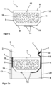
- FIG 1 shows a schematic representation of the spacer I, not according to the invention, comprising a metal base body 5 and a ribbon cable 14 on the outside of the base body 5.
- the metal base body 5 is a hollow body profile comprising two pane contact surfaces 7.1 and 7.2, a glazing interior surface 8, an outer surface 9 and a hollow chamber 10
- the base body 5 consists of aluminum.
- the outer surface 9 has an angled shape, with the portions of the outer surface adjacent to the disk contact surfaces 7.1 and 7.2 being inclined at an angle of 30° to the disk contact surfaces 7.1 and 7.2. This improves the stability of the base body 5.
- the hollow body 10 is filled with a desiccant 11. As a desiccant 11 molecular sieve is used.
- the glazing interior surface 8 of the spacer I has openings 12 which are arranged circumferentially along the glazing interior surface 8 at regular intervals in order to allow gas exchange between the interior of the insulating glazing and the hollow chamber 10 . Any humidity present in the interior is thus absorbed by the desiccant 11 .
- the openings 12 are designed as slits with a width of 0.2 mm and a length of 2 mm.
- the flat ribbon cable 14 is designed as a two-core flat ribbon conductor in the form of a flat laminated cable (FLC) made from two strips of copper foil, surrounded by insulation 18 made from polyethylene terephthalate and attached to the outside 9 of the spacer I.
- FLC flat laminated cable
- the current-carrying wires of the ribbon conductor 14 are surrounded by the insulation 18, which insulates the wires from each other and from the base body 5 and the environment.
- the ribbon cable 14 is attached by means of a hot-melt adhesive, which materially connects the outer surface 9 of the spacer I to the insulation 18 .
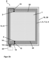
- FIG 2a shows insulating glazing II, not according to the invention, with a spacer I, not according to the invention.
- the sealant 4 connects the pane contact surfaces 7.1 and 7.2 of the spacer I with the panes 19 and 20.
- the glazing interior 3 adjoining the glazing interior surface 8 of the spacer I is defined as the space delimited by the panes 19, 20 and the spacer I.
- the outer space 13 between the panes adjoining the outer surface 9 of the spacer I is a strip-shaped circumferential section of the glazing which is bounded on one side by the two panes 19, 20 and on another side by the spacer I and whose fourth edge is open.
- the glazing interior 3 is filled with argon.
- a sealant 4 is introduced between a respective pane contact surface 7.1 or 7.2 and the adjacent pane 19 or 20, which seals the gap between pane 19, 20 and spacer I.
- the sealant 4 is polyisobutylene.
- An outer seal 6 is fitted on the outer surface 9 in the outer space 13 between the panes and serves to bond the first pane 19 and the second pane 20 .
- the outer seal 6 consists of silicone.
- the outer seal 6 ends flush with the pane edges of the first pane 19 and the second pane 20 .
- the second pane 20 has an electrically switchable functional element 1 on the pane surface facing the glazing interior 3 , which is equipped with a bus bar 22 for making electrical contact with the functional element 1 . With the electrically switchable functional element 1 it is an electrochromic layer.
- spacer I corresponds in figure 1 described. In contrast to this, it is a spacer with a polymeric base body 5.
- the polymeric base body 5 contains styrene-acrylic-nitrile (SAN) and about 35% by weight glass fiber.
- a barrier film (not shown) is applied to the outer surface 9 of the spacer I, which reduces the heat transfer through the polymer base body 5 into the interior of the glazing.
- the barrier film comprises four polymeric layers of polyethylene terephthalate with a thickness of 12 ⁇ m and three metallic layers of aluminum with a thickness of 50 nm. The metallic layers and the polymeric layers are applied alternately, with the two outer layers being formed by polymeric layers .
- the ribbon cable 14 of Figure 2a designed in the form of two copper foil strips as cores without further insulation. Since the outer layer of the barrier film is formed by a polymeric layer and this is non-conductive for the electric current, no insulation of the ribbon cable 14 is necessary.
- the outer seal 6 made of silicone introduced in the outer space between the panes 13 also serves as electrical insulation from the environment.
- the ribbon cable 14 is in cross section according to Figure 2a contacted by an electrical connection cable 15.
- the connection cable 15 is soldered onto a core of the ribbon cable 14 and is thus electrically conductively contacted. Both wires of the ribbon cable have different polarities. Starting from the ribbon cable 14 , the electrical connecting cable 15 is routed along the second pane contact surface 7 .
- the electrical connection cable 15 is contacted there via a contact element 2 with the bus bar 22 .
- the contact element 2 is what is known as a crimp connector, the connection between the electrical connecting cable 15 and the contact element 2 being achieved by squeezing the cable into the crimp connector and the opposite end of the crimp connector being soldered onto the busbar 22 . Due to the routing of the ribbon cable 14 according to the invention in a materially integral manner with the outer surface 9, the outer space 13 between the panes is largely free of lines, so that an unhindered automated filling with the outer seal 6 can take place.
- FIG. 2b shows an overall view of the insulating glazing II according to FIG Figure 2a .
- a running on the outer surface 9 of the spacer I ribbon cable 14 with the busbar 22 of the electrically switchable functional element 1 takes place on two opposite edges of the insulating glazing II, with wires of the ribbon cable 14 from both edges opposite polarity are contacted via an electrical connection cable 15.
- An electrical connection cable 15, as shown in Figure 2a described enters the glazing interior 3 along the second pane contact surface 7.2 and is electrically conductively contacted with the busbar 22 via a contact element 2.
- the spacer I is bent at the corners of the insulating glazing II, so that the ribbon cable 14 on the outside 9 of the spacer I is also continuous at the corners of the glazing.
- Both cores of the ribbon cable 14 are connected in the vicinity of each other to a further electrical connection cable 15 and connected to a voltage source 23 via this.
- the voltage source 23 is a DC voltage source for operating the electrochromic functional element 1 and is located outside the glazing.
- the electrical connecting cables 15 that make contact with one wire of the ribbon conductor 14 are connected to different poles of the voltage source, so that a potential difference arises between the two opposite bus bars 22 .
- the voltage applied to the busbars 22 causes ion migration within the active layer of the electrochromic functional element, as a result of which its transmission is influenced.
- the ribbon cable 14 encompasses the base body 5 along its entire circumference, since a spacer I that was already provided with an integrated ribbon cable 14 was used to produce the spacer frame. For the sake of clarity, in Figure 2a only the sections of the ribbon cable 14 that serve to connect the electrochromic functional element 1 are shown.
- Figure 3a and 3b show a detail of the water- and vapour-tight barrier film 16 on the outside 9 of a polymeric base body 5 of the spacer I according to the invention, with ribbon cables 14 each comprising two cores of copper foil conductors being attached at different points on the barrier film 16.
- the geometry and material composition of the spacer I corresponds to that in Figure 2a described.
- a water- and vapor-tight barrier film is applied, which reduces the heat transfer through the polymer base body 5 into the interior of the glazing.
- the barrier film 16 comprises three polymer layers 16.1 made of polyethylene terephthalate with a thickness of 12 ⁇ m and three metallic layers 16.2 made of aluminum with a thickness of 50 nm.
- the metallic layers 16.2 and the polymer layers 16.1 are each applied alternately, the two outer layers of polymer layers 16.1 are formed.
- the ribbon cable 14 is laminated onto the base body 5 together with the watertight and vapor-tight barrier film 16 ( Figure 3a ).
- the polymeric layer 16.1 adjacent to the base body 5 encloses the ribbon cable 14 and, together with the polymeric base body 5, ensures electrical insulation of the ribbon cable from the environment.
- the barrier film 16 comprises two metallic layers 16.2 attached to both surfaces of a polymeric layer 16.1.
- the ribbon cable 14 is applied to the surface of the barrier film 16 pointing in the direction of the outer space between the panes, insulation 18 being applied between the adjacent metallic layer 16.2 and the ribbon cable 14.
- the insulation 18 is formed by an adhesive layer, here a polyurethane adhesive.
- the adhesive layer is applied to the barrier film 16 and the ribbon cable 14 is introduced into the adhesive layer that has not yet hardened.
- the adhesive layer serves as electrical insulation of the ribbon cable 14 from the underlying metallic layer 16.2.
- FIG 4 shows an embodiment of a triple insulating glazing not according to the invention with a double spacer in cross section.
- the basic structure of the insulating glazing II corresponds to that in Figure 2a and 2 B described.
- the polymer base body 5 has a groove 17 between the first disc contact surface 7.1 and the second disc contact surface 7.2, with a first hollow chamber 10.1 between the groove 17 and the first disc contact surface 7.1 and a second hollow chamber between the groove 17 and the second disc contact surface 7.2 10.2 lies.
- the side flanks of the groove 17 are formed by the walls of the two hollow chambers 10.1 and 10.2, while the bottom surface of the groove 17 borders directly on the outer surface 9.
- the groove 17 runs parallel to the disk contact surfaces 7.
- a third disk 21 is inserted into the groove 17 of the spacer I, which carries an electrically switchable functional element 1, here also an electrochromic functional element, with a bus bar 22 on a disk surface.
- a contact element 2 which is designed as a spring contact.
- the contact element 2 is fitted in the groove 17 before the third disk 21 is inserted.
- an entry opening 25 in the form of a drilled hole. This is produced before the contact element 2 is inserted, so that the contact element 2 can be inserted into it and the contact element protrudes through the base body 5 to the outer surface.
- the third disk 21 is inserted into the groove 17 in such a way that the bus bar 22 points in the direction of the contact element 2 .
- the spring contact is against 21 when inserting the third disc pressed the bus bar 22, whereby the desired electrical contacting comes about.
- the groove 17 also includes an insert 24 which encircles the edge of the third disc 21 and fits flush within the groove 17.
- the insert 24 consists of ethylene-propylene-diene rubber and is cut out in the area of the contact element 2 .
- the insert 24 fixes the third pane 21 free of stress and compensates for thermal expansion of the pane. Furthermore, the insert 24 prevents the development of noise due to the third pane 21 slipping.
- the insulating glazing II according to FIG figure 4 enables electrical contacting of the electrically switchable functional element that is invisible to the observer, the busbar 22 also lying completely inside the groove 17 and being covered by it.
- step IV in the case of double glazing, a first pane 19 or second pane 20 with an electrochromic functional element is attached to a pane contact surface 7 of the spacer I via a sealant 4 .
- the electrochromic functional element is directed in the direction of the later glazing interior 3 .
- step V the second pane 20 is then attached to the pane contact surface 7 that is still available, also using a sealant 4 .
- step IV a third pane 21 is inserted into the groove 17 of the spacer I and in step V the first and second panes 19 and 20 are attached to the pane contact surfaces 7 using a sealant 4.
Description
Die Erfindung betrifft einen Abstandhalter mit integriertem Flachbandkabel eine Isolierverglasung umfassend einen solchen Abstandhalter, ein Verfahren zu dessen Herstellung und dessen Verwendung.The invention relates to a spacer with an integrated ribbon cable, insulating glazing comprising such a spacer, a method for its production and its use.
Isolierverglasungen sind vor allem im Zuge immer strengerer Umweltschutzauflagen nicht mehr aus dem Gebäudebau wegzudenken. Diese werden dabei aus mindestens zwei Scheiben gefertigt, die über mindestens einen umlaufenden Abstandshalter miteinander verbunden sind. Je nach Ausführungsform ist der als Verglasungsinnenraum bezeichnete Zwischenraum der beiden Scheiben luft- oder gasgefüllt, in jedem Fall jedoch frei von Feuchtigkeit. Ein zu hoher Gehalt an Feuchtigkeit im Verglasungszwischenraum führt besonders bei kalten Außentemperaturen zur Kondensation von Wassertropfen im Scheibenzwischenraum, was unbedingt zu vermeiden ist. Zur Aufnahme der nach der Montage im System verbleibenden Restfeuchtigkeit können beispielsweise mit einem Trockenmittel gefüllte Hohlkörperabstandshalter verwendet werden. Da die Aufnahmekapazität des Trockenmittels jedoch begrenzt ist, ist auch in diesem Fall die Abdichtung des Systems von enormer Wichtigkeit um das Eindringen weiterer Feuchtigkeit zu vermeiden.Insulating glazing has become indispensable in building construction, especially in the course of ever stricter environmental protection regulations. These are made from at least two panes, which are connected to one another via at least one circumferential spacer. Depending on the embodiment, the space between the two panes, referred to as the glazing interior, is filled with air or gas, but in any case is free of moisture. Excessive moisture content in the space between the glazing leads to water droplets condensing in the space between the panes, especially when the outside temperature is cold. This must be avoided at all costs. Hollow body spacers filled with a desiccant can be used, for example, to absorb the residual moisture remaining in the system after installation. However, since the absorption capacity of the desiccant is limited, the sealing of the system is also of enormous importance in this case in order to prevent further moisture from penetrating.
Isolierverglasungen können über ihre grundsätzliche Funktion hinausgehend auch weitere Elemente in Form von Einbauten oder Scheiben mit steuerbaren Zusatzfunktionen enthalten. Eine Art von modernen, aktiven Verglasungen sind Verglasungen mit schaltbaren oder regelbaren optischen Eigenschaften. Bei solchen Verglasungen kann beispielsweise die Transmission von Licht in Abhängigkeit einer angelegten elektrischen Spannung aktiv beeinflusst werden. Der Benutzer kann beispielsweise von einen transparenten in einen nicht transparenten Zustand der Verglasung schalten, um den Einblick in einen Raum von außen zu verhindern. Bei anderen Verglasungen kann die Transmission stufenlos geregelt werden, beispielsweise um den Eintrag von Sonnenenergie in einem Raum zu regulieren. Dadurch wird eine unerwünschte Erwärmung von Gebäuden oder Fahrzeuginnenräumen vermieden und der durch Klimaanlagen verursachte Energieverbrauch bzw. COz-Ausstoß reduziert. Aktive Verglasungen dienen folglich nicht nur der optisch ansprechenden Gestaltung von Fassaden und einer angenehmen Lichtgestaltung in Innenräumen, sondern sind auch unter energetischen und ökologischen Gesichtspunkten vorteilhaft.In addition to their basic function, insulating glazing can also contain other elements in the form of built-in components or panes with controllable additional functions. One type of modern, active glazing is glazing with switchable or controllable optical properties. With such glazing, for example, the transmission of light can be actively influenced as a function of an applied electrical voltage. For example, the user can switch the glazing from a transparent to a non-transparent state in order to prevent a view into a room from the outside. With other types of glazing, the transmission can be infinitely adjusted, for example to regulate the entry of solar energy into a room. This prevents unwanted heating of buildings or vehicle interiors and reduces the energy consumption and CO2 emissions caused by air conditioning systems. Active glazing is therefore not only used for the visually appealing design of facades and a pleasant lighting design in interior rooms, but is also advantageous from an energetic and ecological point of view.
Aktive Verglasungen enthalten ein Funktionselement, welches typischerweise eine aktive Schicht zwischen zwei Flächenelektroden umfasst. Die optischen Eigenschaften der aktiven Schicht können durch eine an die Flächenelektroden angelegte Spannung verändert werden. Ein Beispiel hierfür sind elektrochrome Funktionselemente, die beispielsweise aus
Wird eine aktive Verglasung in einer Isolierverglasung integriert, so ist die Spannungszufuhr der aktiven Verglasung gas- und wasserdicht auszugestalten um eine hinreichende Qualität und Lebensdauer der Isolierverglasung zu gewährleisten. In
Darüber hinaus ist in der Praxis häufig eine elektrische Kontaktierung an mehreren Stellen der Isolierverglasung notwendig. Dabei wird das Anschlusskabel nach dem Stand der Technik im äußeren Scheibenzwischenraum um den Abstandhalterrahmen herumgeführt. Der Abstandhalter ist über ein sogenanntes primäres Dichtmittel mit den Scheiben der Isolierverglasung verklebt, während im äußeren Scheibenzwischenraum ein sekundäres Dichtmittel eingebracht ist, das diesen ausfüllt und eventuell vorhandene elektrische Anschlusskabel umgibt. Das automatisierte Verfüllen des äußeren Scheibenzwischenraums in Gegenwart elektrischer Anschlusskabel erweist sich jedoch als problematisch, da diese beispielsweise einen Roboterarm mit Extrusionsdüse räumlich behindern können. Ferner dürfen keine Luftblasen im äußeren Scheibenzwischenraum verbleiben, beispielsweise zwischen Anschlusskabel und Abstandhalter. Das Volumen der eingeschlossenen Luft variiert mit sich ändernden klimatischen Bedingungen und führt dauerhaft zu Undichtigkeiten der Isolierverglasung im Bereich des Lufteinschlusses.In addition, in practice it is often necessary to make electrical contacts at several points on the insulating glazing. According to the prior art, the connecting cable is routed around the spacer frame in the outer space between the panes. The spacer is bonded to the panes of the insulating glazing using a so-called primary sealant, while a secondary sealant is inserted in the outer space between the panes, which fills it and surrounds any electrical connection cables that may be present. However, the automated filling of the outer space between the panes in the presence of electrical connection cables has proven to be problematic, since these can spatially obstruct a robot arm with an extrusion nozzle, for example. Furthermore, no air bubbles may remain in the outer space between the panes, for example between the connection cable and the spacer. The volume of trapped air varies with changing climatic conditions and permanently leads to leaks in the insulating glazing in the area of the trapped air.
Um eine verbesserte Dichtigkeit von Isolierverglasungen zu gewährleisten sind bereits die verschiedensten Modifikationen im Bereich der Abstandshalter bekannt. Eine Maßnahme zur Verbesserung der Dichtigkeit von Isolierverglasungen ist die Beschichtung von polymeren Abstandshaltern mit Metallfolien oder alternierenden Metall-Polymer-Schichtsystemen, wie beispielsweise in
Flachbandkabel sind auf dem Gebiet der Elektrotechnik bekannt und werden beispielsweise zur elektrischen Kontaktierung in Computern verwendet. Unter dem Begriff Flachbandkabel sind dem Fachmann mehradrige Kabel, deren Adern parallel geführt sind, bekannt. Im Gegensatz zu einer zylindrischen Bauweise verfügen Flachbandkabel über eine wesentlich geringere Aufbauhöhe. Die Adern eines Flachbandkabels können beispielsweise als parallel verlaufende Litzen mit Isolierung ausgeführt sein, wobei die Isolierung die Formgebung des Kabels und den Abstand der Adern zueinander (sogenanntes Rastermaß) bestimmt.Ribbon cables are known in the field of electrical engineering and are used, for example, for electrical contacting in computers. The term flat cable is known to those skilled in the art for multi-wire cables whose wires are routed in parallel. In contrast to a cylindrical design, ribbon cables have a significantly lower installation height. The cores of a ribbon cable can be designed, for example, as parallel strands with insulation, with the insulation determining the shape of the cable and the distance between the cores (so-called pitch).
Eine Untergruppe der Flachbandkabel sind die Flachbandleitungen, auch als Flat Flex Cable (FFC) bekannt. Diese verfügen ebenfalls über parallel verlaufende Adern, die jedoch als Metallfolien ausgeführt sind. Als die Adern trennende Isolation wird in der Regel eine Kunststofffolie eingesetzt. Als mögliche Bauformen der FFC sind laminierte Flachbandleitungen, sogenannte Flat Laminated Cable (FLC), und extrudierte Flachbandleitungen, sogenannte Flat Extruded Cable (FEC), bekannt. Bei der laminierten Ausführungsform (FLC) befindet sich dabei ein Klebstoff zwischen Metallfolie und umgebender Isolierung, während die Adern bei extrudierten Flachbandleitern (FEC) unmittelbar von der Isolierung umgeben sind. Darüber hinaus sind flexible strukturierte Leiterplatten (Flexible Printed Circuit, FPC) als weitere mögliche Bauform bekannt, die vor allem bei komplexen Leiterstrukturen zum Einsatz kommt.A subgroup of flat ribbon cables are flat ribbon cables, also known as flat flex cables (FFC). These also have parallel wires, but these are designed as metal foils. A plastic foil is usually used as the insulation separating the wires. Laminated ribbon cables, so-called flat laminated cables (FLC), and extruded ribbon cables, so-called flat extruded cables (FEC), are known as possible designs of the FFC. In the laminated version (FLC), there is an adhesive between the metal foil and the surrounding insulation, while the wires in extruded flat conductors (FEC) are directly surrounded by the insulation. In addition, flexible structured printed circuit boards (Flexible Printed Circuit, FPC) are known as another possible design, which is mainly used for complex conductor structures.
Flachbandleitungen (FFC) werden aufgrund ihrer platzsparenden Bauweise auch gerne in Kabelbäumen von Kraftfahrzeugen verwendet. So wird beispielsweise in
In
Aufgabe der vorliegenden Erfindung ist es, einen Abstandshalter, der zu einer verbesserten Abdichtung von Isolierverglasungen mit elektrischen Zuleitungen führt, eine Isolierverglasung mit diesem Abstandshalter, sowie ein wirtschaftliches Verfahren zur Herstellung der Isolierverglasung bereitzustellen.The object of the present invention is to provide a spacer that leads to improved sealing of insulating glazing with electrical supply lines, insulating glazing with this spacer, and an economical method for producing the insulating glazing.
Die Aufgabe der vorliegenden Erfindung wird erfindungsgemäß durch einen Abstandhalter mit integriertem Flachbandkabel, eine Isolierverglasung mit Abstandhalter, ein Verfahren zu deren Herstellung und der Verwendung des Abstandhalters nach den unabhängigen Ansprüchen 1, 11 und 13 gelöst. Bevorzugte Ausführungen der Erfindung gehen aus den Unteransprüchen hervor.The object of the present invention is achieved according to the invention by a spacer with an integrated ribbon cable, insulating glazing with a spacer, a method for its production and the use of the spacer according to
Der erfindungsgemäße Abstandhalter mit integrierten Flachbandkabel für Isolierverglasungen umfasst mindestens einen polymeren Grundkörper umfassend zwei Scheibenkontaktflächen, eine Verglasungsinnenraumfläche und eine Außenfläche. Das mindestens eine Flachbandkabel verläuft an der Außenfläche und ist direkt oder indirekt stoffschlüssig mit der Außenfläche verbunden. Als direkte Verbindung ist dabei eine unmittelbare Anbindung zwischen Flachbandkabel und Grundkörper zu verstehen. Diese tritt beispielsweise ein, wenn die Komponenten ohne Zwischenlage anderer Schichten verbunden sind. Dies ist beispielsweise mittels Coextrusion, Verschweißen oder Laminieren ohne Klebstoff der Fall. Eine indirekte Verbindung entsteht sowohl bei Verkleben oder Laminieren unter Verwendung eines Klebstoffes als auch bei Zwischenlage anderer Komponenten wie beispielsweise einer Barrierefolie. In jedem Fall wird eine stoffschlüssige und vollflächige Verbindung zwischen Grundkörper und Flachbandkabel geschaffen, wobei keine Hohlräume und kein Dichtmittel zwischen Grundkörper und Flachbandkabel vorhanden sind. Hohlräume könnten durch Ausdehnung der darin enthaltenen Luft zu Undichtigkeiten der Isolierverglasung führen. Dichtmittel sind zur Verfüllung des Zwischenraums zwischen Grundkörper und Flachbandkabel ungeeignet, da diese schmale Hohlräume in der Regel nur schlecht ausfüllen und luftgefüllte Hohlräume zurückbleiben. Als Dichtmittel werden in diesem Sinne sowohl die gängigen Dichtmittel zum Anbringen der Scheiben an den Scheibenkontaktflächen des Abstandhalters (oft als primäres Dichtmittel bezeichnet) als auch die äußere Abdichtung (oft als sekundäres Dichtmittel bezeichnet) gesehen.The spacer according to the invention with integrated ribbon cable for insulating glazing comprises at least one polymer base body comprising two pane contact surfaces, a glazing interior surface and an outer surface. The at least one ribbon cable runs on the outer surface and is directly or indirectly connected to the outer surface with a material fit. A direct connection is to be understood as an immediate connection between the ribbon cable and the base body. This occurs, for example, when the components are connected without the interposition of other layers. This is the case, for example, by means of coextrusion, welding or laminating without adhesive. An indirect connection occurs both when gluing or laminating using an adhesive and when other components are interposed, such as a barrier film. In any case, an integral and full-surface connection is created between the base body and the ribbon cable, with no cavities and no sealant being present between the base body and the ribbon cable. Cavities could lead to leaks in the insulating glazing due to the expansion of the air contained in them. Sealants are unsuitable for filling the space between the base body and the ribbon cable, since they generally fill narrow cavities poorly and air-filled cavities remain. In this sense, sealants are seen as both the standard sealants for attaching the discs to the disc contact surfaces of the spacer (often referred to as the primary sealant) and the outer seal (often referred to as the secondary sealant).
Die Scheibenkontaktflächen, die Verglasungsinnenraumfläche und die Außenfläche des Grundkörpers bilden gemeinsam einen umlaufend geschlossenen Körper. Dadurch wird die strukturelle Integrität sowie die Dichtheit gegenüber Gasen und Wasser gewährleistet. Der polymere Grundkörper ist mit einer gas- und wasserdichten Barrierefolie versehen.The pane contact surfaces, the glazing interior surface and the outer surface of the base body together form a body that is closed all the way round. This ensures structural integrity and gas and water tightness. The polymer body is provided with a gas- and water-tight barrier film.
Die stoffschlüssige Verbindung von Grundkörper und Flachbandkabel ermöglicht eine hohlraumfreie Anbindung des Flachbandkabels an den Abstandhalter, so dass bei Verfüllen des äußeren Scheibenzwischenraums der Isolierverglasung keine Luftblasen in der äußeren Abdichtung verbleiben, die bei thermischer Ausdehnung der eingeschlossenen Luft eine Undichtigkeit des Randverbunds der Isolierverglasung hervorrufen.The integral connection of the base body and the ribbon cable allows the ribbon cable to be connected to the spacer without cavities, so that when the outer space between the panes of the insulating glazing is filled, no air bubbles remain in the outer seal, which could cause the edge seal of the insulating glazing to leak if the enclosed air thermally expands.
Ferner ermöglicht der erfindungsgemäße Abstandhalter die industriell automatisierbare Weiterverarbeitung eines Abstandhalterrahmens umfassend den erfindungsgemäßen Abstandhalter. Da das als elektrische Zuleitung dienende Flachbandkabel stoffschlüssig an der Außenfläche des Abstandhalters geführt wird, kann eine automatisierte Verfüllung des Randbereichs der Verglasung erfolgen, ohne dass die elektrische Zuleitung ein Hindernis für die entlang der Außenseite des Abstandhalters geführte Materialdüse darstellt.Furthermore, the spacer according to the invention enables the industrially automated further processing of a spacer frame comprising the spacer according to the invention spacers. Since the ribbon cable serving as the electrical supply line is routed in a materially bonded manner on the outer surface of the spacer, the edge area of the glazing can be automatically filled without the electrical supply line representing an obstacle for the material nozzle routed along the outside of the spacer.
Im Sinne der Erfindung wird der Abstandhalter mit integriertem Flachbandkabel insbesondere dann angewandt, wenn beispielsweise eine Spannungsversorgung an mehreren Stellen der Isolierverglasung notwendig ist und ein nach dem Stand der Technik frei im äußeren Scheibenzwischenraum geführtes Anschlusskabel die automatisierte Weiterverarbeitung stark beeinträchtigen würde.According to the invention, the spacer with an integrated ribbon cable is used in particular when, for example, a power supply is required at several points on the insulating glazing and a connection cable that is routed freely in the outer space between the panes according to the prior art would severely impair automated further processing.
Ein wesentlicher Vorteil der Erfindung liegt auch im hohen Vorfertigungsgrad des erfindungsgemäßen Abstandhalters mit integrierter elektrischer Zuleitung. Die Leitungen werden dabei bereits im Fertigungsprozess des Abstandhalters in diesem integriert, so dass während der Herstellung der Isolierverglasung keine manuelle Installation der Zuleitungen mehr erforderlich ist. Bei Herstellung der Isolierverglasung sind die bereits auf der Außenfläche des Abstandhalters vorhandenen Zuleitungen lediglich an den erforderlichen Stellen zu kontaktieren. Dazu kann das Flachbandkabel beispielsweise mit einem elektrischen Anschlusskabel elektrisch leitend kontaktiert werden, das zum Anschluss des elektrisch schaltbaren Funktionselementes dient. Da die manuelle Installation der Zuleitungen entfällt, kann der Automatisierungsgrad der Isolierglasherstellung weiter erhöht werden. Ferner ist die Position der elektrischen Zuleitungen exakt zu bestimmen, da diese nicht als lose Kabel im Randverbund liegen, sondern in einer definierten Position auf dem Grundkörper angebracht sind. Dies erleichtert die elektrische Kontaktierung.An essential advantage of the invention also lies in the high degree of prefabrication of the spacer according to the invention with an integrated electrical supply line. The lines are already integrated into the spacer during the manufacturing process, so that manual installation of the supply lines is no longer necessary during the manufacture of the insulating glazing. When producing the insulating glazing, the supply lines already present on the outer surface of the spacer only have to be contacted at the required points. For this purpose, the ribbon cable can be electrically conductively contacted, for example, with an electrical connection cable that is used to connect the electrically switchable functional element. Since the manual installation of the supply lines is no longer necessary, the degree of automation in insulating glass production can be further increased. Furthermore, the position of the electrical supply lines must be determined precisely, as these are not loose cables in the edge bond, but are attached in a defined position on the base body. This facilitates electrical contacting.
Die erste Scheibenkontaktfläche und die zweite Scheibenkontaktfläche stellen die Seiten des Abstandhalters dar, an denen beim Einbau des Abstandhalters die Montage der äußeren Scheiben (erste Scheibe und zweite Scheibe) einer Isolierverglasung erfolgt. Die erste Scheibenkontaktfläche und die zweite Scheibenkontaktfläche verlaufen parallel zueinander.The first pane contact surface and the second pane contact surface represent the sides of the spacer on which the outer panes (first pane and second pane) of insulating glazing are mounted when the spacer is installed. The first disk contact surface and the second disk contact surface are parallel to one another.
Die Verglasungsinnenraumfläche ist als die Fläche des Abstandhaltergrundkörpers definiert, die nach Einbau des Abstandhalters in einer Isolierverglasung in Richtung des Innenraums der Verglasung weisen. Die Verglasungsinnenraumfläche liegt dabei zwischen der ersten und der zweiten Scheibe.The glazing interior area is defined as the area of the spacer body which, after installation of the spacer in insulating glazing, faces towards the interior of the glazing. The glazing interior surface lies between the first and the second pane.
Die Außenfläche des Abstandhaltergrundkörpers ist die der Verglasungsinnenraumfläche gegenüberliegende Seite, die vom Innenraum der Isolierverglasung weg in Richtung einer äußeren Versiegelung weist.The outer surface of the spacer body is the side opposite the glazing interior surface, facing away from the interior of the insulating glazing toward an exterior seal.
Die Außenfläche des Abstandhalters kann in einer möglichen Ausführungsform jeweils benachbart zu den Scheibenkontaktflächen abgewinkelt sein, wodurch eine erhöhte Stabilität des Grundkörpers erzielt wird. Die Außenfläche kann benachbart zu den Scheibenkontaktflächen beispielsweise um jeweils 30-60°, relativ zur Außenfläche, abgewinkelt sein.In one possible embodiment, the outer surface of the spacer can be angled in each case adjacent to the pane contact surfaces, as a result of which increased stability of the base body is achieved. The outer surface may be angled adjacent to the disk contact surfaces, for example by 30-60° each time relative to the outer surface.
Das erfindungsgemäß an der Außenfläche des Abstandhalters eingebrachte Flachbandkabel ist ein ein- oder mehradriges Kabel, dessen Adern parallel geführt sind. Dadurch verfügt das Flachbandkabel über eine wesentlich geringere Aufbauhöhe als die üblicherweise im äußeren Scheibenzwischenraum verwendeten zylindrischen Anschlusskabel. Alle gängigen Flachbandkabel sind aufgrund ihrer flachen Bauweise im Sinne der Erfindung geeignet. Durch ihre flache Bauweise liegen Flachbandkabel bei stoffschlüssiger Verbindung mit der Außenfläche des Abstandhalters bündig an diesem an ohne einen Lufteinschluss zwischen Grundkörper und Kabel oder nach Verfüllung seitlich des Kabels hervorzurufen.The ribbon cable introduced according to the invention on the outer surface of the spacer is a single-core or multi-core cable whose cores are routed in parallel. As a result, the flat ribbon cable has a significantly lower installation height than the cylindrical connection cables usually used in the outer space between the panes. All common ribbon cables are suitable for the purposes of the invention due to their flat design. Due to their flat design, ribbon cables lie flush with the outer surface of the spacer when they are firmly bonded to the latter without causing an air pocket between the base body and the cable or, after filling, on the side of the cable.
In einer möglichen Ausführungsform des Flachbandkabels umfasst dieses mehrere parallel verlaufende Litzen. Diese sind bevorzugt von einer Isolierung umgeben, die die Litzen zueinander beabstandet und neben ihren isolierenden Eigenschaften auch die Formstabilität des Kabels gewährleistet. Aufgrund der runden Form der benachbarten Litzen ergibt sich eine strukturierte, geriffelte, Oberfläche eines Flachbandkabels enthaltend Litzenleiter. Vor diesem Hintergrund wird ein Flachbandkabel umfassend Litzenleiter bevorzugt mittels eines Klebers auf der Außenfläche des Abstandhalters angebracht, da der Klebstoff die durch die geriffelte Oberfläche entstehenden Hohlräume ausfüllt.In one possible embodiment of the ribbon cable, this comprises a plurality of parallel strands. These are preferably surrounded by an insulation that keeps the strands at a distance from one another and, in addition to their insulating properties, also ensures the dimensional stability of the cable. Due to the round shape of the adjacent strands, a structured, corrugated surface of a ribbon cable containing stranded conductors results. Against this background, a ribbon cable comprising stranded conductors is preferably attached to the outer surface of the spacer by means of an adhesive, since the adhesive fills the cavities created by the corrugated surface.
Bevorzugt gehört das im Sinne der Erfindung verwendete Flachbandkabel zur Gruppe der Flachbandleitungen, einer Sonderbauform der Flachbandkabel. Flachbandleitungen (oder Flachbandleiter) sind auch unter den Begriffen Folienleiter, flexible Flachkabel, oder Flachleiter bekannt. Besonders gebräuchlich ist der international verwendete Ausdruck Flat Flex Cable (FFC). Diese verfügen ebenfalls über parallel verlaufende Adern, die jedoch als Metallfolien ausgeführt sind. Je nach Anwendung kann der Flachbandleiter auch eine einzelne Ader umfassen.The ribbon cable used within the meaning of the invention preferably belongs to the group of ribbon cables, a special type of ribbon cable. Ribbon cables (or ribbon conductors) are also known by the terms foil conductors, flexible flat cables, or flat conductors. The internationally used expression Flat Flex Cable (FFC) is particularly common. These also have parallel wires, but these are designed as metal foils. Depending on the application, the ribbon cable can also include a single core.
Flachbandleiter sind in verschiedenen Ausführungsformen mit einer oder mehreren als Metallfolie ausgeführten Adern kommerziell erhältlich. In der Regel umfassen diese eine Isolation in Form einer Kunststofffolie, die die mindestens eine Ader umgibt. Die Verbindung des Leiters (Metallfolienstreifen) und der Isolierung (Kunststofffolie) erfolgt dabei durch Lamination (sogenannte Flat Laminated Cable (FLC)) oder Extrusion (sogenannte Flat Extruded Cable (FEC)). Bei der laminierten Ausführungsform (FLC) befindet sich dabei ein Klebstoff zwischen Metallfolie und umgebender Isolierung, während die Adern bei extrudierten Flachbandleitern (FEC) unmittelbar von der Isolierung umgeben sind. Diese bereits mit einer isolierenden Kunststofffolie ummantelten Flachbandleiter beider Ausführungsformen sind bevorzugt über einen Klebstoff, über Schweißtechniken (z.B. Ultraschallschweißen) oder Lamination auf der Außenseite des Abstandhalters montierbar. Auf diese Art und Weise ist ein bestehender Abstandhalter einfach mit einem Flachbandleiter nachzurüsten. Da Flachbandleiter über Metallfolien anstelle von Litzen verfügen, kann die Aufbauhöhe der Leitungen weiter verringert werden. Ferner weisen Flachbandleiter eine ebene Oberfläche auf, so dass das Risiko von Lufteinschlüssen weiter vermindert wird.Ribbon conductors are commercially available in various embodiments with one or more cores designed as a metal foil. As a rule, these include insulation in the form of a plastic film that surrounds the at least one wire. The conductor (metal foil strips) and the insulation (plastic foil) are connected by lamination (so-called Flat Laminated Cable (FLC)) or extrusion (so-called Flat Extruded Cable (FEC)). In the laminated version (FLC), there is an adhesive between the metal foil and the surrounding insulation, while the wires in extruded flat conductors (FEC) are directly surrounded by the insulation. These flat ribbon conductors, which are already encased in an insulating plastic film, in both embodiments can be mounted on the outside of the spacer, preferably using an adhesive, using welding techniques (eg ultrasonic welding) or lamination. In this way, an existing spacer can easily be retrofitted with a ribbon cable. Since ribbon conductors have metal foils instead of strands, the overall height of the cables can be further reduced. Furthermore, ribbon conductors have a flat surface, so that the risk of air pockets is further reduced.
Eine weitere Bauform der Flachbandleiter sind strukturierte Leiterplatten (sogenannte Flexible Printed Circuits (FPC)). Diese werden in alternativen Ausführungsformen der Erfindung eingesetzt, beispielsweise wenn eine komplexe Leiterstruktur mit mehreren Abzweigungen gewünscht ist.Structured circuit boards (so-called Flexible Printed Circuits (FPC)) are another type of ribbon conductor. These are used in alternative embodiments of the invention, for example when a complex conductor structure with multiple branches is desired.
Flachbandleiter enthalten bevorzugt Kupfer und/oder Kupferlegierungen. Alternativ können auch andere elektrisch leitende Materialien verwendet werden. Beispiele hierfür sind Aluminium, Gold, Silber oder Zinn sowie Legierungen davon.Ribbon conductors preferably contain copper and/or copper alloys. Alternatively, other electrically conductive materials can also be used. Examples of this are aluminum, gold, silver or tin and alloys thereof.
Die elektrische Zuleitung besitzt bevorzugt einen Leitungsquerschnitt von 0,08 mm2 bis 2,5 mm2.The electrical supply line preferably has a line cross-section of 0.08 mm 2 to 2.5 mm 2 .
Beispiele für Folienleiter werden in
Flachbandleiter bestehen bevorzugt aus einem verzinnten Kupferband mit einer Dicke von 0,03 mm bis 0,45 mm und einer Breite von 0,2 mm bis 6,6 mm. Kupfer hat sich für solche Leiterbahnen bewährt, da es eine gute elektrische Leitfähigkeit sowie eine gute Verarbeitbarkeit zu Folien besitzt. Gleichzeitig sind die Materialkosten niedrig.Ribbon conductors preferably consist of a tinned copper strip with a thickness of 0.03 mm to 0.45 mm and a width of 0.2 mm to 6.6 mm. Copper has proven itself for such conductor tracks because it has good electrical conductivity and good processing properties to form foils. At the same time, the material costs are low.
Im Sinne der Erfindung werden besonders bevorzugt Flachbandleiter mit einer Dicke von 0,1 mm bis 0,45 mm und einer Breite von 1,0 mm bis 7,0 mm verwendet. Dadurch ist sowohl eine eine gute elektrische Kontaktierbarkeit als auch eine ausreichende Stromtragfähigkeit gewährleistet. Der im Rahmen dieser Abmaße entstehende rechteckige Querschnitt ist ferner vorteilhaft um eine ausreichend große Anbindungsfläche an den Grundkörper über die Breite des Flachbandkabels und eine nur geringe Aufbauhöhe, gegeben durch die geringe Dicke des Flachbandkabels, zu gewährleisten.According to the invention, it is particularly preferred to use ribbon conductors with a thickness of 0.1 mm to 0.45 mm and a width of 1.0 mm to 7.0 mm. This ensures both good electrical contactability and sufficient current-carrying capacity. The resulting rectangular cross-section within these dimensions is also advantageous in order to ensure a sufficiently large connection area to the base body across the width of the ribbon cable and only a small installation height, given the small thickness of the ribbon cable.
Sofern der Flachbandleiter mehrere Leiterbahnen umfasst, stellt das sogenannte Rastermaß eine weitere wichtige Kenngröße zur Beschreibung des Flachbandleiters dar. Das Rastermaß bezeichnet dabei den Abstand zweier paralleler Leiterbahnen, jeweils gemessen von der Mitte der Leiterbahnen, und beträgt für gängige Flachbandleiter 0,5 mm bis 2,54 mm.If the ribbon conductor comprises several conductor tracks, the so-called grid dimension is another important parameter for describing the ribbon conductor. The grid dimension describes the distance between two parallel conductor tracks, measured from the center of the conductor tracks, and is 0.5 mm to 2 mm for common ribbon conductors .54mm.
In einer möglichen Ausführungsform weist die erfindungsgemäße Isolierverglasung einen Abstandhalter mit polymerem Grundkörper umfassend mindestens eine Hohlkammer auf. Ein geeigneter Abstandhalter mit polymerem Grundkörper ist beispielsweise in
Dem Fachmann bekannte Hohlprofilabstandhalter enthalten mindestens eine Hohlkammer in einem in der Regel polymeren oder metallischen Grundkörper. Die Hohlkammer grenzt an die Verglasungsinnenraumfläche, wobei die Verglasungsinnenraumfläche sich oberhalb der Hohlkammer befindet und die Außenfläche des Abstandhalters sich unterhalb der Hohlkammer befindet. Oberhalb ist in diesem Zusammenhang als dem inneren Scheibenzwischenraum der Isolierverglasung zugewandt und unterhalb als dem Scheibeninnenraum abgewandt definiert.Hollow profile spacers known to those skilled in the art contain at least one hollow chamber in a generally polymeric or metallic base body. The plenum abuts the glazing interior surface with the glazing interior surface being above the plenum and the outer surface of the spacer being below the plenum. In this context, above is defined as facing towards the inner space between the panes of the insulating glazing and below as facing away from the interior of the pane.
Die Hohlkammer des Abstandhalters führt zu einer Gewichtsreduktion im Vergleich zu einem massiv ausgeformten Abstandhalter und steht zur Aufnahme von weiteren Komponenten, wie beispielsweise eines Trockenmittels, zur Verfügung.The hollow chamber of the spacer results in a weight reduction compared to a solidly formed spacer and is available for accommodating other components, such as a desiccant.
In der erfindungsgemäßen Ausführungsform des Abstandhalters umfasst dieser einen polymeren Grundkörper. Dies ist vorteilhaft, da die Wärmeleitfähigkeit von Kunststoffen wesentlich geringer ist als die Wärmeleitfähigkeit von Metallen. Des Weiteren weist der Kunststoff des polymeren Grundkörpers einen spezifischen Widerstand von mindestens 108 Ω cm auf und ist somit nichtleitend für elektrischen Strom. Dies ist besonders vorteilhaft, da es in diesem Fall keiner weiteren Isolierung zwischen Grundkörper und elektrischem Leiter des Flachbandkabels bedarf. Auch in diesem Fall kann ein Flachbandkabel, bevorzugt ein Flachbandleiter, mit oder ohne eine äußere Isolierung auf den polymeren Grundkörper aufgebracht werden. Die sich ergebenen Vorteile wurden bereits beschrieben.In the embodiment of the spacer according to the invention, this comprises a polymer base body. This is advantageous because the thermal conductivity of plastics is significantly lower than the thermal conductivity of metals. Furthermore, the plastic of the polymer base body has a specific resistance of at least 10 8 Ω cm and is therefore non-conductive for electric current. This is particularly advantageous since in this case, no further insulation is required between the base body and the electrical conductor of the ribbon cable. In this case, too, a ribbon cable, preferably a ribbon conductor, can be applied to the polymer base body with or without external insulation. The resulting advantages have already been described.
Die Verwendung von Abstandhaltern mit polymerem Grundkörper hat sich als besonders vorteilhaft erwiesen, da in diesem Fall stoffschlüssige Anbindung innerhalb einer Barrierefolie des Grundkörpers auf einfache Art und Weise möglich ist. Ferner können wichtige Kernfunktionen des Randverbundes, wie Gas- und Wasserdichtigkeit, geringer Wärmedurchgangskoeffizient, Aufnahme von Trockenmittel und Zuleitungen zur elektrischen Kontaktierung, in Form eines einzelnen Bauteils zur Verfügung gestellt werden. Dadurch wird die Produktion der Isolierverglasung entscheidend vereinfacht.The use of spacers with a polymeric base body has proven to be particularly advantageous, since in this case a cohesive connection within a barrier film of the base body is possible in a simple manner. Furthermore, important core functions of the edge compound, such as gas and water tightness, low heat transfer coefficient, absorption of desiccant and supply lines for electrical contacting, can be provided in the form of a single component. This significantly simplifies the production of the insulating glazing.
Sofern das Flachbandkabel eine Isolierung umfasst, so besitzt diese einen spezifischen Widerstand von größer oder gleich 108 Ω cm. Die Isolierung umfasst bevorzugt Polyvinylchlorid, Polyethernaphthalat, Polyethylen, Polyimid, Gummi, Polyurethan und/oder Polymere aus der Gruppe der Polyester. Insbesondere Polyesterisolationen sind sowohl kostengünstig als auch umweltverträglich und werden vor allem in Form einer den Flachbandleiter umgebenden Folie verwendet.If the ribbon cable includes insulation, this has a specific resistance of greater than or equal to 10 8 Ω cm. The insulation preferably comprises polyvinyl chloride, polyether naphthalate, polyethylene, polyimide, rubber, polyurethane and/or polymers from the polyester group. In particular, polyester insulation is both inexpensive and environmentally friendly and is used primarily in the form of a film surrounding the ribbon conductor.
Da der erfindungsgemäße Abstandhalter einen polymeren Grundkörper aufweist, werden weitere Maßnahmen zur Verbesserung der Gasdichtigkeit des Grundkörpers vorgesehen. Erfindungsgemäß ist mindestens auf der Außenfläche des polymeren Grundkörpers, bevorzugt auf der Außenfläche und auf einem Teil der Scheibenkontaktflächen, eine gas- und dampfdichte Barriere aufgebracht. Die gas- und dampfdichte Barriere verbessert die Dichtigkeit des Abstandhalters gegen Gasverlust und Eindringen von Feuchtigkeit. Bevorzugt ist die Barriere auf etwa der Hälfte bis zwei Drittel der Scheibenkontaktflächen aufgebracht. Ein geeigneter Abstandhalter mit polymerem Grundkörper ist beispielsweise in
Die gas- und dampfdichte Barriere ist auf der Außenfläche des polymeren Abstandhalters als Folie ausgeführt. Diese Barrierefolie enthält mindestens eine polymere Schicht sowie eine metallische Schicht oder eine keramische Schicht. Dabei beträgt die Schichtdicke der polymeren Schicht zwischen 5 µm und 80 µm, während metallische Schichten und/oder keramische Schichten mit einer Dicke von 10 nm bis 200 nm eingesetzt werden. Innerhalb der genannten Schichtdicken wird eine besonders gute Dichtigkeit der Barrierefolie erreicht. Die Barrierefolie kann auf dem polymeren Grundkörper aufgebracht werden, beispielsweise geklebt werden. Alternativ kann die Folie mit dem Grundkörper zusammen co-extrudiert werden.The gas-tight and vapor-tight barrier is designed as a film on the outer surface of the polymer spacer. This barrier film contains at least one polymeric layer and a metallic layer or a ceramic layer. The layer thickness of the polymer layer is between 5 μm and 80 μm, while metallic layers and/or ceramic layers with a thickness of 10 nm to 200 nm are used. A particularly good impermeability of the barrier film is achieved within the layer thicknesses mentioned. The barrier film can be applied to the polymer base body, for example glued. Alternatively, the film can be co-extruded with the base body.
Besonders bevorzugt enthält die Barrierefolie mindestens zwei metallische Schichten und/oder keramische Schichten, die alternierend mit mindestens einer polymeren Schicht angeordnet sind. Die Schichtdicken der einzelnen Schichten sind bevorzugt wie im vorhergehenden Absatz beschrieben. Bevorzugt werden die außenliegenden Schichten dabei von der polymeren Schicht gebildet. In dieser Anordnung sind die metallischen Schichten besonders gut vor Beschädigung geschützt. Die alternierenden Schichten der Barrierefolie können auf die verschiedensten nach dem Stand der Technik bekannten Methoden verbunden bzw. aufeinander aufgetragen werden. Methoden zur Abscheidung metallischer oder keramischer Schichten sind dem Fachmann hinlänglich bekannt. Die Verwendung einer Barrierefolie mit alternierender Schichtenabfolge ist besonders vorteilhaft im Hinblick auf die Dichtigkeit des Systems. Ein Fehler in einer der Schichten führt dabei nicht zu einem Funktionsverlust der Barrierefolie. Im Vergleich dazu kann bei einer Einzelschicht bereits ein kleiner Defekt zu einem vollständigen Versagen führen. Des Weiteren ist die Auftragung mehrerer dünner Schichten im Vergleich zu einer dicken Schicht vorteilhaft, da mit steigender Schichtdicke die Gefahr interner Haftungsprobleme ansteigt. Ferner verfügen dickere Schichten über eine höhere Leitfähigkeit, so dass eine derartige Folie thermodynamisch weniger geeignet ist.The barrier film particularly preferably contains at least two metallic layers and/or ceramic layers which are arranged alternating with at least one polymeric layer. The layer thicknesses of the individual layers are preferably as described in the previous paragraph. The outer layers are preferably formed by the polymeric layer. In this arrangement, the metallic layers are particularly well protected from damage. The alternating layers of the barrier film can be connected or applied to one another using a wide variety of methods known in the prior art. Methods for depositing metallic or ceramic layers are well known to those skilled in the art. The use of a barrier film with an alternating sequence of layers is particularly advantageous with regard to the tightness of the system. A defect in one of the layers does not lead to a loss of function of the barrier film. In comparison, even a small defect in a single layer can lead to complete failure. Furthermore, the application of several thin layers is advantageous compared to one thick layer, since the risk of internal adhesion problems increases with increasing layer thickness. Furthermore, thicker layers have a higher conductivity, so that such a film is thermodynamically less suitable.
Die polymere Schicht der Folie umfasst bevorzugt Polyethylenterephthalat, Ethylenvinylalkohol, Polyvinylidenchlorid, Polyamide, Polyethylen, Polypropylen, Silikone, Acrylonitrile, Polyacrylate, Polymethylacrylate und/oder Copolymere oder Gemische davon. Die metallische Schicht enthält bevorzugt Eisen, Aluminium, Silber, Kupfer, Gold, Chrom und/oder Legierungen oder Oxide davon. Die keramische Schicht der Folie enthält bevorzugt Siliziumoxide und/oder Siliziumnitride.The polymeric layer of the film preferably comprises polyethylene terephthalate, ethylene vinyl alcohol, polyvinylidene chloride, polyamides, polyethylene, polypropylene, silicones, acrylonitriles, polyacrylates, polymethyl acrylates and/or copolymers or mixtures thereof. The metallic layer preferably contains iron, aluminum, silver, copper, gold, chromium and/or alloys or oxides thereof. The ceramic layer of the foil preferably contains silicon oxides and/or silicon nitrides.
In einer besonders bevorzugten Ausführungsform weist die gas- und dampfdichte Barriere mindestens eine metallische Schicht oder keramische Schicht auf, die als Beschichtung ausgeführt ist und Aluminium, Aluminiumoxide und / oder Siliciumoxide enthält und bevorzugt über ein PVD-Verfahren (physikalische Gasphasenabscheidung) aufgebracht ist.In a particularly preferred embodiment, the gas-tight and vapor-tight barrier has at least one metallic layer or ceramic layer that is designed as a coating and contains aluminum, aluminum oxides and/or silicon oxides and is preferably applied using a PVD method (physical vapor deposition).
Der polymere Grundkörper enthält bevorzugt Polyethylen (PE), Polycarbonate (PC), Polypropylen (PP), Polystyrol, Polybutadien, Polynitrile, Polyester, Polyurethane, Polymethylmetacrylate, Polyacrylate, Polyamide, Polyethylenterephthalat (PET), Polybutylenterephthalat (PBT), bevorzugt Acrylnitril-Butadien-Styrol (ABS), Acrylester-Styrol-Acrylnitril (ASA), Acrylnitril-Butadien-Styrol/Polycarbonat (ABS/PC), Styrol-Acrylnitril (SAN), PET/PC, PBT/PC und/oder Copolymere oder Gemische davon. Mit diesen Materialien werden besonders gute Ergebnisse erzielt.The polymeric base preferably contains polyethylene (PE), polycarbonate (PC), polypropylene (PP), polystyrene, polybutadiene, polynitrile, polyester, polyurethane, polymethylmetacrylate, polyacrylate, polyamide, polyethylene terephthalate (PET), polybutylene terephthalate (PBT), preferably acrylonitrile butadiene -Styrene (ABS), acrylester-styrene-acrylonitrile (ASA), acrylonitrile-butadiene-styrene/polycarbonate (ABS/PC), styrene-acrylonitrile (SAN), PET/PC, PBT/PC and/or copolymers or mixtures thereof. Particularly good results are achieved with these materials.
Bevorzugt ist der polymere Grundkörper glasfaserverstärkt. Durch die Wahl des Glasfaseranteils im Grundkörper kann der Wärmeausdehnungskoeffizient des Grundkörpers variiert und angepasst werden. Durch Anpassung des Wärmeausdehnungskoeffizienten des polymeren Grundkörpers und der Barrierefolie lassen sich temperaturbedingte Spannungen zwischen den unterschiedlichen Materialien und ein Abplatzen der Barrierefolie oder vermeiden. Der Grundkörper weist bevorzugt einen Glasfaseranteil von 20 % bis 50 %, besonders bevorzugt von 30 % bis 40 % auf. Der Glasfaseranteil im polymeren Grundkörper verbessert gleichzeitig die Festigkeit und Stabilität.The polymer base body is preferably glass fiber reinforced. The thermal expansion coefficient of the base body can be varied and adjusted by selecting the glass fiber content in the base body. Temperature-related stresses between the different materials and flaking of the barrier film can be avoided by adapting the coefficient of thermal expansion of the polymer base body and the barrier film. The base body preferably has a glass fiber content of 20% to 50%, particularly preferably 30% to 40%. The glass fiber content in the polymer body improves strength and stability at the same time.
In einer weiteren bevorzugten Ausführungsform ist der polymere Grundkörper gefüllt durch Glashohlkugeln oder Glasblasen. Diese Glashohlkugeln haben einen Durchmesser von 10 µm bis 20 µm und verbessern die Stabilität des polymeren Hohlprofils. Geeignete Glaskugeln sind unter dem Namen "3M™ Glass Bubbles" käuflich erhältlich. Besonders bevorzugt enthält der polymere Grundkörper Polymere, Glasfasern und Glaskugeln. Eine Beimischung von Glaskugeln führt zu einer Verbesserung der thermischen Eigenschaften des Hohlprofils.In a further preferred embodiment, the polymeric base body is filled with hollow glass spheres or glass bubbles. These hollow glass spheres have a diameter of 10 µm to 20 µm and improve the stability of the polymer hollow profile. Suitable glass beads are commercially available under the name "3M ™ Glass Bubbles". The polymeric base particularly preferably contains polymers, glass fibers and glass beads. Adding glass beads leads to an improvement in the thermal properties of the hollow profile.
Das Flachbandkabel ist unmittelbar über die gas- und dampfdichte Barrierefolie in den Abstandhalter mit polymerem Grundkörper integriert. Dabei werden aufgrund ihrer geringen Bauhöhe bevorzugt Flachbandleiter verwendet.The ribbon cable is integrated directly into the spacer with a polymer body via the gas-tight and vapour-tight barrier film. Because of their low overall height, flat conductors are preferably used.
In einer ersten erfindungsgemäßen Ausführungsform ist ein Flachbandkabel zwischen der Außenfläche des polymeren Grundkörpers und der gas- und dampfdichten Barrierefolie integriert. Dabei kann beispielsweise mindestens ein Metallfolienleiter vor Anbringen der gas- und dampfdichten Barrierefolie auf den Grundkörper aufgebracht werden und die gas- und dampfdichte Barriere so auf den Metallfolienleiter aufgelegt werden, dass eine polymere Schicht benachbart zum Metallfolienleiter liegt. Somit wird bereits alleinig durch die Anordnung der Komponenten eine elektrische Isolation des elektrischen Leiters zur Umgebung erreicht. Sofern ein Flachbandkabel in Nachbarschaft zu einer metallischen Schicht der Barrierefolie angebracht werden soll, so wird eine Isolierung oder ein isolierender Klebstoff zwischen der metallischen Schicht und dem elektrischen Leiter des Flachbandkabels vorgesehen. Die Integration eines Flachbandkabels zwischen Grundkörper und Barrierefolie hat den Vorteil, dass kein gesonderter Prozessschritt zur Integration des Flachbandkabels notwendig ist und dieses gleichzeitig mit der Barrierefolie mit dem Grundkörper verklebt, verschweißt (bevorzugt mittels Ultraschallschweißen), laminiert oder coextrudiert werden kann.In a first embodiment according to the invention, a ribbon cable is integrated between the outer surface of the polymer base body and the gas-tight and vapor-tight barrier film. For example, at least one metal foil conductor can be applied to the base body before the gas-tight and vapor-tight barrier film is attached, and the gas-tight and vapor-tight barrier can be placed on the metal foil conductor in such a way that a polymeric layer is adjacent to the metal foil conductor. Electrical insulation of the electrical conductor from the environment is thus achieved simply by the arrangement of the components. If a ribbon cable is to be attached in the vicinity of a metallic layer of the barrier film, insulation or an insulating adhesive is provided between the metallic layer and the electrical conductor of the ribbon cable. The integration of a ribbon cable between the base body and the barrier film has the advantage that no separate process step is necessary to integrate the ribbon cable and that it can be glued, welded (preferably by means of ultrasonic welding), laminated or coextruded to the base body with the barrier film at the same time.
In einer zweiten erfindungsgemäßen Ausführungsform verläuft das Flachbandkabel, auch hier aufgrund der Aufbauhöhe bevorzugt ein Flachbandleiter, innerhalb der gas- und dampfdichten Barrierefolie und grenzt bevorzugt an zwei polymere Schichten. Bezüglich der Verbindung der Komponenten gelten die für die erste erfindungsgemäße Ausführungsform beschriebenen Details. Die zweite erfindungsgemäße Ausführungsform ist vorteilhaft, da beispielsweise bei Verkleben, Laminieren oder Verschweißen der Barrierefolie und des Grundkörpers das Flachbandkabel bereits in der Barrierefolie integriert ist. So muss das Flachbandkabel nicht als einzelne Komponente zwischengelegt werden, sondern wird zusammen mit der Barrierefolie bereitgestellt.In a second embodiment according to the invention, the ribbon cable, here also preferably a ribbon conductor due to the structural height, runs within the gas-tight and vapor-tight barrier film and preferably borders on two polymer layers. With regard to the connection of the components, the details described for the first embodiment according to the invention apply. The second embodiment according to the invention is advantageous because, for example, when the barrier film and the base body are glued, laminated or welded, the ribbon cable is already integrated in the barrier film. The ribbon cable does not have to be inserted as an individual component, but is provided together with the barrier film.
In einer dritten erfindungsgemäßen Ausführungsform ist das Flachbandkabel an der der Außenfläche des Grundkörpers abgewandten Oberfläche der gas- und dampfdichten Barrierefolie angebracht. Bezüglich möglicher Verbindetechniken, der Notwendigkeit einer Isolation des elektrischen Leiters und weiterer Details gelten die Ausführungen zur ersten und zweiten erfindungsgemäßen Ausführungsform. Die dritte erfindungsgemäße Ausführungsform ist vorteilhaft, da die gas- und dampfdichte Barrierefolie bei Kontaktierung des elektrischen Leiters nicht punktuell im Bereich der Kontaktierung entfernt werden muss. Ein Entfernen der Folie birgt das Risiko auch benachbarte Bereiche der Außenfläche zu beschädigen und so eine Undichtigkeit des Abstandhalters herbeizuführen. Ferner kann das Flachbandkabel in dieser Ausführungsform auch als an mindestens einer Oberfläche nicht isolierter Metallfolienstreifen ausgeführt werden. Dieser wird so auf den Grundkörper mit Barrierefolie aufgebracht, dass die Oberfläche ohne Isolierung in Richtung des äußeren Scheibenzwischenraums weist und somit das Abisolieren des elektrischen Leiters entfällt.In a third embodiment according to the invention, the ribbon cable is attached to the surface of the gas-tight and vapor-tight barrier film that faces away from the outer surface of the base body. With regard to possible connection techniques, the need for insulation of the electrical conductor and other details, the statements on the first apply and second embodiment of the invention. The third embodiment of the invention is advantageous because the Gas and vapour-tight barrier film does not have to be selectively removed in the contact area when contacting the electrical conductor. Removing the film carries the risk of also damaging adjacent areas of the outer surface and thus causing the spacer to leak. Furthermore, the ribbon cable in this embodiment can also be designed as a metal foil strip that is not insulated on at least one surface. This is applied to the base body with the barrier film in such a way that the surface without insulation points in the direction of the outer space between the panes, meaning that the electrical conductor does not have to be stripped.
Besonders bevorzugt ist das Flachbandkabel gemäß der beschriebenen ersten, zweiten oder dritten Ausführungsform gemeinsam mit der Barrierrefolie auf den polymeren Grundkörper aufgeklebt, auflaminiert oder bei Coextrusion von polymerem Grundkörper und Barrierefolie innerhalb der Barrierefolie oder auf einer der Oberflächen der Barrierefolie in den Schichtstapel integriert.The ribbon cable according to the first, second or third embodiment described is particularly preferably glued or laminated to the polymeric base body together with the barrier film or, in the case of coextrusion of polymeric base body and barrier film, is integrated into the layer stack within the barrier film or on one of the surfaces of the barrier film.
Das Flachbandkabel verläuft bevorzugt auf einer Länge von mindestens 10 cm, besonders bevorzugt mindestens 20 cm, insbesondere mindestens 30 cm entlang der Außenfläche eines aus dem erfindungsgemäßen Abstandhalter zusammengesetzten Abstandhalterrahmen. Die Vorteile der Erfindung kommen besonders zum Tragen, wenn längere Abschnitte einer frei im äußeren Scheibenzwischenraum liegenden Zuleitung vermieden werden können, da diese im weiteren Verarbeitungsprozess der Isolierverglasung besonders hinderlich sind.The ribbon cable preferably runs over a length of at least 10 cm, particularly preferably at least 20 cm, in particular at least 30 cm, along the outer surface of a spacer frame composed of the spacer according to the invention. The advantages of the invention are particularly evident when longer sections of a supply line lying freely in the outer space between the panes can be avoided, since these are particularly obstructive in the further processing of the insulating glazing.
Das Flachbandkabel ist geeignet um mit einer Spannungsversorgung und einem elektrischen Verbraucher kontaktiert zu werden. Nach Montage des erfindungsgemäßen Abstandhalters in einer Isolierverglasung liegt die Spannungsversorgung dabei außerhalb des Verglasungsinnenraums und der elektrische Verbraucher innerhalb des Verglasungsinnenraums.The ribbon cable is suitable for contacting a power supply and an electrical consumer. After the spacer according to the invention has been installed in insulating glazing, the power supply is outside the interior of the glazing and the electrical load is inside the interior of the glazing.
Das Flachbandkabel ist bevorzugt mittels jeweils mindestens eines elektrischen Anschlusskabels an dem elektrischen Verbraucher und der Spannungsversorgung kontaktiert. Dem Fachmann sind diverse als elektrische Anschlusskabel geeignete Kabelformen bekannt. Das mindestens eine elektrische Anschlusskabel kann beispielsweise als Litzenleiter oder Flachbandleiter, bevorzugt als Flachbandleiter, ausgeführt sein. Die in einer bevorzugten Ausführungsform an der Außenseite des Grundkörpers aufgebrachten Flachbandleiter eignen sich aufgrund ihrer flachen Bauform sehr gut zur Verwendung als elektrische Anschlusskabel. Ein elektrisches Anschlusskabel kann nach Montage einer Isolierverglasung mit erfindungsgemäßem Abstandhalter beispielsweise entlang der ersten oder zweiten Scheibenkontaktfläche in den Verglasungsinnenraum geführt werden. Eine flache Bauart des Anschlusskabels ist dabei vorteilhaft um auch an der Stelle, an der das Anschlusskabel in den Verglasungsinnenraum eingeführt wird, eine möglichst hohe Schichtdicke des die Scheiben und den Abstandhalter verbindenden Dichtmittels zu erreichen. Ferner liegt ein Flachbandleiter als elektrisches Anschlusskabel auch an der Kontaktierungsstelle zwischen an der Außenfläche verlaufendem Flachbandkabel und Anschlusskabel sehr flach an der Außenfläche des Grundkörpers an. Bevorzugt werden alle elektrischen Anschlusskabel und das an der Außenfläche des Grundkörpers verlaufende Flachbandkabel als Flachbandleiter (umfassend Metallfolien) ausgeführt. Dies ist vorteilhaft um in Summe einen möglichst flachen Aufbau sowie eine optimale elektrische Kontaktierung zu erreichen.The ribbon cable is preferably contacted by means of at least one electrical connection cable on the electrical consumer and the power supply. A person skilled in the art is familiar with various cable shapes suitable as electrical connection cables. The at least one electrical connection cable can be designed, for example, as a stranded wire or flat cable, preferably as a flat cable. In a preferred embodiment, the flat ribbon conductors applied to the outside of the base body are very well suited for use as electrical connection cables. After installing insulating glazing with a spacer according to the invention, an electrical connection cable can be routed, for example, along the first or second pane contact surface into the interior of the glazing. A flat design of the connection cable is advantageous in order to achieve the greatest possible layer thickness of the sealant connecting the panes and the spacer at the point at which the connection cable is inserted into the interior of the glazing. Furthermore, a ribbon conductor as an electrical connection cable also lies very flat against the outer surface of the base body at the contact point between the ribbon cable running on the outer surface and the connection cable. All electrical connection cables and the flat ribbon cable running on the outer surface of the base body are preferably designed as flat ribbon conductors (comprising metal foils). This is advantageous in order to achieve the flattest possible overall structure and optimal electrical contacting.
Das mindestens eine elektrische Anschlusskabel ist durch Löten, Kleben mittels eines elektrisch leitfähigen Klebstoffs, Schweißen (z.B. Ultraschallschweißen) oder mittels anderer dem Fachmann bekannter Verfahren zum Verbinden elektrischer Leiter elektrisch leitend mit dem an der Außenfläche des Abstandhalters befindlichen Flachbandkabel verbunden.The at least one electrical connecting cable is electrically conductively connected to the flat cable located on the outer surface of the spacer by soldering, gluing using an electrically conductive adhesive, welding (e.g. ultrasonic welding) or using other methods known to those skilled in the art for connecting electrical conductors.
Bevorzugt wird eine Isolierung des Flachbandkabels in dem Bereich, in dem die Kontaktierung des elektrischen Anschlusskabels erfolgen soll, entfernt. Geeignete Verfahren zum Entfernen der Isolierung sind dem Fachmann hinreichend bekannt. Dazu zählen beispielsweise mechanische Verfahren wie Schaben, Schleifen und Fräsen oder auch thermische Verfahren wie thermische Abisolation mit Prozessgas oder thermische Abisolation mittels Laserverfahren (beispielsweise mittels eines COz-Lasers).An insulation of the ribbon cable is preferably removed in the area in which the electrical connection cable is to be contacted. Suitable methods for removing the insulation are well known to those skilled in the art. These include, for example, mechanical processes such as scraping, grinding and milling or also thermal processes such as thermal stripping with process gas or thermal stripping using laser processes (for example using a CO2 laser).
In einer möglichen Ausführungsform ist das mindestens eine elektrische Anschlusskabel über einen elektrisch leitenden Kontaktstift, beispielsweise einen Metallstift, der im Bereich des Flachbandkabels in den Abstandhalter eingepresst wird, mit dem Flachbandkabel kontaktiert. Das Anschlusskabel wird dabei mittels gängiger Methoden zur elektrischen Kontaktierung an den Kontaktstift angebunden. Eine Kontaktierung über einen in die Außenfläche eingedrückten Kontaktstift ist insbesondere bei Verwendung polymerer Grundkörper mit Barrierefolien vorteilhaft. Eine Entfernung eventuell vorhandener elektrischer Isolierungen, die mit einer unerwünschten Beschädigung der Barrierefolie einhergehen kann, entfällt dabei.In one possible embodiment, the at least one electrical connection cable is in contact with the flat cable via an electrically conductive contact pin, for example a metal pin, which is pressed into the spacer in the area of the flat cable. The connection cable is connected to the contact pin using common methods for electrical contacting. Contacting via a contact pin pressed into the outer surface is particularly advantageous when using polymer base bodies with barrier films. There is no need to remove any electrical insulation that may be present, which could result in unwanted damage to the barrier film.
In einer besonders bevorzugten Ausführungsform ist der Abstandhalter ein Doppelabstandhalter, der mindestens eine zusätzliche Scheibe in einer Nut aufnehmen kann. Diese werden beispielsweise für Dreifachverglasungen verwendet, bei denen die dritte Scheibe in einer Nut zwischen der ersten Scheibe und der zweiten Scheibe eingesetzt wird. Derartige Abstandhalter sind unter anderem aus
Der Doppelabstandhalter umfasst einen Grundkörper mit erster Scheibenkontaktfläche und einer parallel dazu verlaufenden zweiten Scheibenkontaktfläche, eine Verglasungsinnenraumfläche und eine Außenfläche. Der Grundaufbau entspricht dem beschriebenen Abstandhalter für Doppelverglasungen. Die Verglasungsinnenraumfläche wird durch die Nut in zwei Teilbereiche unterteilt. In den Grundkörper sind optional eine erste Hohlkammer und eine zweite Hohlkammer eingebracht, die durch die Nut voneinander getrennt sind. Die erste Hohlkammer grenzt in diesem Fall an einen ersten Teilbereich der Verglasungsinnenraumfläche, während die zweite Hohlkammer an einen zweiten Teilbereich der Verglasungsinnenraumfläche angrenzt, wobei die Verglasungsinnenraumfläche sich oberhalb der Hohlkammern befinden und die Außenfläche sich unterhalb der Hohlkammern befindet. Oberhalb ist in diesem Zusammenhang als dem Scheibeninnenraum einer Isolierverglasung mit erfindungsgemäßem Abstandshalter zugewandt und unterhalb als dem Scheibeninnenraum abgewandt definiert. Da die Nut zwischen der ersten Verglasungsinnenraumfläche und zweiten Verglasungsinnenraumfläche verläuft, begrenzt sie diese seitlich und trennt die erste Hohlkammer und die zweite Hohlkammer voneinander. Die Seitenflanken der Nut werden dabei von den Wänden der ersten Hohlkammer und der zweiten Hohlkammer gebildet. Alternativ kann der Raum seitlich der Nut auch massiv ausgestaltet sein anstelle von Hohlkammern. Die Nut bildet eine Vertiefung, die geeignet ist die mittlere Scheibe (dritte Scheibe) einer Isolierverglasung aufzunehmen. Dadurch wird die Position der dritten Scheibe über zwei Seitenflanken der Nut sowie die Bodenfläche der Nut fixiert. Eine erste und eine zweite Scheibe können an der ersten und zweiten Scheibenkontaktfläche des Abstandhalters angebracht werden.The double spacer comprises a base body with a first pane contact surface and a second pane contact surface running parallel thereto, a glazing interior surface and an outer surface. The basic structure corresponds to the spacer described for double glazing. The glazing interior surface is divided into two sections by the groove. A first hollow chamber and a second hollow chamber, which are separated from one another by the groove, are optionally introduced into the base body. In this case, the first cavity borders on a first partial area of the glazing interior surface, while the second cavity borders on a second partial region of the glazing interior surface, with the glazing interior surface being located above the cavities and the outer surface being located below the cavities. In this context, above is defined as facing towards the pane interior of insulating glazing with a spacer according to the invention and below as facing away from the pane interior. Since the groove runs between the first interior glazing surface and the second interior glazing surface, it delimits them laterally and separates the first cavity and the second cavity from one another. The side flanks of the groove are formed by the walls of the first hollow chamber and the second hollow chamber. Alternatively, the space on the side of the groove can also be solid instead of hollow chambers. The groove forms a depression that is suitable for receiving the middle pane (third pane) of insulating glazing. This fixes the position of the third disk over two side flanks of the groove and the bottom surface of the groove. A first and second disc can be attached to the first and second disc contacting surfaces of the spacer.
Die Führung des Flachbandkabels an der Außenfläche eines Doppelabstandhalters sowie dessen Ausführungsdetails sind analog zu den bereits beschriebenen Details des Abstandhalters ohne Nut. Im Falle eines Abstandhalters für Dreifach- oder Mehrfachisolierverglasungen besteht jedoch eine zusätzliche Möglichkeit zur Einführung eines elektrischen Anschlusskabels in den Verglasungsinnenraum. Ein elektrisches Anschlusskabel kann nicht nur entlang der ersten oder zweiten Scheibenkontaktfläche in den Verglasungsinnenraum geführt werden, sondern auch in die Nut eingeführt werden. Dies ist vorteilhaft, da auf diese Weise ein auf der dritten Scheibe einer Isolierverglasung befindliches elektrisch schaltbares Funktionselement für den Betrachter unsichtbar innerhalb der Nut elektrisch kontaktiert werden kann.The routing of the ribbon cable on the outer surface of a double spacer and its design details are analogous to the details of the spacer without a groove already described. In the case of a spacer for triple or multiple insulating glazing, however, there is an additional possibility of introducing an electrical connection cable into the interior of the glazing. An electrical connection cable can not only be routed along the first or second pane contact surface into the interior of the glazing, but also inserted into the groove. This is advantageous because in this way an electrically switchable functional element located on the third pane of insulating glazing can be electrically contacted within the groove so that it is invisible to the viewer.
Optional umfasst die Nut eines erfindungsgemäßen Doppelabstandhalters eine Einlage. Die Einlage verhindert ein Verrutschen der Scheibe und eine dadurch bedingte Geräuschentwicklung beim Öffnen und Schließen des Fensters. Die Einlage kompensiert des Weiteren die thermische Ausdehnung der dritten Scheibe bei Erwärmung, so dass unabhängig von den klimatischen Bedingungen eine spannungsfreie Fixierung gewährleistet ist. Die Einlage kann im Bereich der elektrischen Kontaktierung ausgespart sein um den für die Kontaktierung benötigten Platz zur Verfügung zu stellen.Optionally, the groove of a double spacer according to the invention includes an insert. The insert prevents the pane from slipping and the resulting noise when opening and closing the window. The insert also compensates for the thermal expansion of the third pane when it heats up, so that tension-free fixing is guaranteed regardless of the climatic conditions. The insert can be cut out in the area of the electrical contact in order to provide the space required for the contact.
In einer besonders bevorzugten Ausführungsform der Erfindung ist der Abstandhalter ein Abstandhalter für Dreifachverglasungen umfassend mindestens eine Nut zur Aufnahme einer dritten Scheibe, wobei die Nut eine Eintrittsöffnung, bevorzugt in der Bodenfläche der Nut, umfasst. Dies ist vorteilhaft, da die Eintrittsöffnung im Einbauzustand des Abstandhalters für den Betrachter nicht sichtbar ist und gleichzeitig die Verklebung des Abstandhalters mit den benachbarten Scheiben nicht durch ein hindurchtretendes Kabel beeinflusst wird.In a particularly preferred embodiment of the invention, the spacer is a spacer for triple glazing comprising at least one groove for receiving a third pane, the groove comprising an entry opening, preferably in the bottom surface of the groove. This is advantageous because the entry opening is not visible to the observer when the spacer is installed and at the same time the bonding of the spacer to the adjacent panes is not influenced by a cable passing through.
Bevorzugt umfasst die Nut ein Kontaktelement, das ein elektrisch schaltbares Funktionselement der dritten Scheibe elektrisch leitend kontaktiert. Besonders bevorzugt ragt das Kontaktelement durch die Eintrittsöffnung der Nut hindurch und tritt an der Außenfläche des Abstandhalters aus diesem heraus. Dieser Teil des Kontaktelements befindet sich demnach in direkter Nachbarschaft zum an der Außenseite des Grundkörpers befindlichen Flachbandkabel und kann somit auf einfache Art und Weise über ein elektrisches Anschlusskabel mit diesem kontaktiert werden.The groove preferably includes a contact element which makes electrically conductive contact with an electrically switchable functional element of the third pane. Particularly preferably, the contact element protrudes through the entry opening of the groove and emerges from the spacer on the outer surface of the latter. This part of the contact element is therefore located in the direct vicinity of the ribbon cable located on the outside of the base body and can therefore be contacted with it in a simple manner via an electrical connection cable.
Bevorzugt weist die Verglasungsinnenraumfläche des Abstandhalters mindestens eine Öffnung auf. Bevorzugt sind mehrere Öffnungen in der Verglasungsinnenraumfläche angebracht. Die Gesamtzahl der Öffnungen hängt dabei von der Größe der Isolierverglasung ab. Die Öffnungen verbinden die Hohlkammer mit dem inneren Scheibenzwischenraum, wodurch ein Gasaustausch zwischen diesen möglich wird. Dadurch wird eine Aufnahme von Luftfeuchtigkeit durch ein in der Hohlkammer befindliches Trockenmittel erlaubt und somit ein Beschlagen der Scheiben verhindert. Die Öffnungen sind bevorzugt als Schlitze ausgeführt, besonders bevorzugt als Schlitze mit einer Breite von 0,2 mm und einer Länge von 2 mm. Die Schlitze gewährleisten einen optimalen Luftaustausch ohne dass Trockenmittel aus der Hohlkammer in den inneren Scheibenzwischenraum eindringen kann.Preferably, the interior glazing surface of the spacer has at least one opening. Preferably, multiple openings are provided in the glazing interior surface. The total number of openings depends on the size of the insulating glazing. The openings connect the hollow chamber with the inner space between the panes, which enables gas exchange between them. This allows the moisture in the air to be absorbed by a desiccant in the hollow chamber, thus preventing the windows from fogging up. The openings are preferably designed as slits, particularly preferably as slits with a width of 0.2 mm and a length of 2 mm. The slits ensure an optimal exchange of air without desiccant from the hollow chamber being able to penetrate into the inner space between the panes.
Der Abstandhalter weist bevorzugt entlang der Scheibenkontaktflächen eine Höhe von 5 mm bis 15 mm, besonders bevorzugt von 5 mm bis 10 mm, auf.The spacer preferably has a height of 5 mm to 15 mm, particularly preferably 5 mm to 10 mm, along the pane contact surfaces.
Die Breite der Verglasungsinnenraumfläche, beziehungsweise die Breite der Teilbereiche der Verglasungsinnenraumfläche, die den Abstand zweier benachbarter Scheiben der Isolierverglasung definiert, beträgt 4 mm bis 30 mm, bevorzugt 8 mm bis 16 mm.The width of the interior glazing surface, or the width of the partial areas of the interior glazing surface, which defines the distance between two adjacent panes of the insulating glazing, is 4 mm to 30 mm, preferably 8 mm to 16 mm.
Die Erfindung umfasst des Weiteren eine Isolierverglasung mit erfindungsgemäßem Abstandhalter. Die Isolierverglasung umfassend mindestens eine erste Scheibe, eine zweite Scheibe und einen die Scheiben umfassenden umlaufenden erfindungsgemäßen Abstandhalter mit Flachbandkabel.The invention also includes insulating glazing with a spacer according to the invention. The insulating glazing comprises at least a first pane, a second pane and a circumferential spacer with ribbon cable according to the invention, which encompasses the panes.
An die Verglasungsinnenraumfläche des Abstandhalters angrenzend befindet sich der Verglasungsinnenraum der Isolierverglasung. Die Außenfläche des Abstandhalters grenzt hingegen an den äußeren Scheibenzwischenraum. Die erste Scheibe ist dabei an der ersten Scheibenkontaktfläche des Abstandhalters und die zweite Scheibe an der zweiten Scheibenkontaktfläche des Abstandhalters angebracht.Adjacent to the glazing interior surface of the spacer is the glazing interior of the insulating glazing. The outer surface of the spacer, on the other hand, borders on the outer space between the panes. The first pane is attached to the first pane contact surface of the spacer and the second pane is attached to the second pane contact surface of the spacer.
Im Verglasungsinnenraum der Isolierverglasung befindet sich ein elektrisch schaltbares Funktionselement, dessen Spannungsversorgung über das an der Außenfläche des Abstandhalters befindliche Flachbandkabel gewährleistet werden soll. Dazu wird das Flachbandkabel an einer Stelle über ein elektrisches Anschlusskabel mit der Spannungsversorgung kontaktiert und an mindestens einer anderen Stelle über ein elektrisches Anschlusskabel mit dem elektrisch schaltbaren Funktionselement im Verglasungsinnenraum elektrisch leitend verbunden. Die verschiedenen Adern des Flachbandkabels können beispielsweise zur Trennung verschiedener Polaritäten genutzt werden.In the glazing interior of the insulating glazing there is an electrically switchable functional element, the power supply of which is to be ensured via the ribbon cable located on the outer surface of the spacer. For this purpose, the ribbon cable is contacted at one point via an electrical connecting cable with the power supply and at least one other point via an electrical connecting cable with the electrically switchable functional element in the glazing interior is electrically conductively connected. The different strands of the ribbon cable can be used to separate different polarities, for example.
Die erste und die zweite Scheibe sind an den Scheibenkontaktflächen bevorzugt über ein Dichtmittel angebracht, das zwischen der ersten Scheibenkontaktfläche und der ersten Scheibe und/oder der zweiten Scheibenkontaktfläche und der zweiten Scheibe angebracht ist.The first and second discs are attached to the disc contacting surfaces preferably via a sealant attached between the first disc contacting surface and the first disc and/or the second disc contacting surface and the second disc.
Das Dichtmittel enthält bevorzugt Butylkautschuk, Polyisobutylen, Polyethylenvinylalkohol, Ethylenvinylacetat, Polyolefin-Kautschuk, Polypropylen, Polyethylen, Copolymere und/oder Gemische davon.The sealant preferably contains butyl rubber, polyisobutylene, polyethylene vinyl alcohol, ethylene vinyl acetate, polyolefin rubber, polypropylene, polyethylene, copolymers and/or mixtures thereof.
Das Dichtmittel ist bevorzugt in mit einer Dicke von 0,1 mm bis 0,8 mm, besonders bevorzugt 0,2 mm bis 0,4 mm in den Spalt zwischen Abstandhalter und Scheiben eingebracht.The sealant is preferably introduced into the gap between spacer and panes with a thickness of 0.1 mm to 0.8 mm, particularly preferably 0.2 mm to 0.4 mm.
Der äußere Scheibenzwischenraum der Isolierverglasung ist bevorzugt mit einer äußeren Abdichtung verfüllt. Diese äußere Abdichtung dient vor allem der Verklebung der beiden Scheiben und somit der mechanischen Stabilität der Isolierverglasung.The outer space between the panes of the insulating glazing is preferably filled with an outer seal. This outer seal is primarily used to bond the two panes and thus the mechanical stability of the insulating glazing.
Die äußere Abdichtung enthält bevorzugt Polysulfide, Silikone, Silikonkautschuk, Polyurethane, Polyacrylate, Copolymere und/oder Gemische davon. Derartige Stoffe haben eine sehr gute Haftung auf Glas, so dass die äußere Abdichtung eine sichere Verklebung der Scheiben gewährleistet. Die Dicke der äußeren Abdichtung beträgt bevorzugt 2 mm bis 30 mm, besonders bevorzugt 5 mm bis 10 mm.The outer seal preferably contains polysulfides, silicones, silicone rubber, polyurethanes, polyacrylates, copolymers and/or mixtures thereof. Such substances have very good adhesion to glass, so that the outer seal ensures that the panes are securely bonded. The thickness of the outer seal is preferably 2 mm to 30 mm, particularly preferably 5 mm to 10 mm.
Die äußere Abdichtung kann zusätzlich auch der Isolation des Flachbandkabels gegenüber der Umgebung dienen. Dies ist der Fall, wenn auf der der Außenseite des Abstandhalters abgewandten Oberfläche des Flachbandkabels keine gesonderte Isolierung angebracht ist. Dies ist vorteilhaft, da das Flachbandkabel mit elektrischen Anschlusskabeln kontaktiert werden kann ohne zunächst eine Isolierung entfernen zu müssen. Die Isolierung der Anordnung gegenüber der Umgebung findet somit erst bei Verfüllen des äußeren Scheibenzwischenraums statt. Bei der Materialauswahl der äußeren Abdichtung muss gegebenenfalls die Größe der anliegenden Spannung beachtet werden, um ein Abdichtungsmaterial mit hinreichenden Isolationseigenschaften auszuwählen. Der elektrische Widerstand der genannten Abdichtungsmaterialien ist aus der Literatur bekannt, so dass der Fachmann eine derartige Abschätzung mit geringem Aufwand treffen kann. Viele der in Verglasungen gängigen elektrisch schaltbaren Funktionselemente benötigen jedoch nur geringe Spannungen, so dass eine ausreichende Isolierung in der Regel mit allen der genannten Materialien problemlos möglich ist.The outer seal can also serve to insulate the ribbon cable from the environment. This is the case when no separate insulation is applied to the surface of the ribbon cable facing away from the outside of the spacer. This is advantageous since the ribbon cable can be contacted with electrical connection cables without first having to remove insulation. The isolation of the arrangement from the environment therefore only takes place when the outer space between the panes is filled. When selecting the material for the outer seal, the magnitude of the applied voltage may have to be taken into account in order to select a sealing material with sufficient insulating properties. The electrical resistance of the sealing materials mentioned is known from the literature, so that a person skilled in the art can make such an assessment with little effort. However, many of the electrically switchable functional elements commonly used in glazing require only low voltages, so that sufficient insulation is usually possible without any problems using all of the materials mentioned.
Je nach Ausgestaltung des elektrisch schaltbaren Funktionselements können mehrere Flachbandkabel oder Adern eines Flachbandkabels unterschiedlicher Polarität bestehen, die an verschiedenen Positionen des elektrisch schaltbaren Funktionselements mit diesem kontaktiert werden.Depending on the configuration of the electrically switchable functional element, there can be a plurality of flat ribbon cables or wires of a flat ribbon cable of different polarity, which are contacted with the electrically switchable functional element at different positions of the latter.
Das eigentliche Funktionselement mit elektrisch schaltbaren optischen Eigenschaften wird mindestens durch zwei elektrisch leitfähige Schichten und eine aktive Schicht gebildet. Die elektrisch leitfähigen Schichten bilden dabei Flächenelektroden. Durch Anlegen einer Spannung an die Flächenelektroden, beziehungsweise durch Änderung der an den Flächenelektroden anliegenden Spannung können die optischen Eigenschaften der aktiven Schicht, insbesondere die Transmission und/oder die Streuung von sichtbarem Licht beeinflusst werden.The actual functional element with electrically switchable optical properties is formed by at least two electrically conductive layers and one active layer. The electrically conductive layers form surface electrodes. The optical properties of the active layer, in particular the transmission and/or the scattering of visible light, can be influenced by applying a voltage to the surface electrodes or by changing the voltage present at the surface electrodes.
Die elektrisch leitfähigen Schichten sind bevorzugt transparent. Die elektrisch leitfähigen Schichten enthalten bevorzugt zumindest ein Metall, eine Metalllegierung oder ein transparentes leitfähiges Oxid (transparent conducting oxide, TCO). Die elektrisch leitfähigen Schichten enthalten bevorzugt zumindest ein transparentes leitfähiges Oxid.The electrically conductive layers are preferably transparent. The electrically conductive layers preferably contain at least one metal, one metal alloy or one transparent conductive oxide ( transparent conducting oxide, TCO). The electrically conductive layers preferably contain at least one transparent conductive oxide.
Die elektrisch leitfähigen Schichten weisen bevorzugt eine Dicke von 10 nm bis 2 µm auf, besonders bevorzugt von 20 nm bis 1 µm, ganz besonders bevorzugt von 30 nm bis 500 nm und insbesondere von 50 nm bis 200 nm. Damit wird eine vorteilhafte elektrische Kontaktierung der aktiven Schicht erreicht.The electrically conductive layers preferably have a thickness of 10 nm to 2 μm, particularly preferably from 20 nm to 1 μm, very particularly preferably from 30 nm to 500 nm and in particular from 50 nm to 200 nm active layer reached.
Die elektrisch leitfähigen Schichten sind dafür vorgesehen, mit zumindest einer externen Spannungsquelle elektrisch leitend verbunden zu werden, um als Flächenelektroden des schaltbaren Funktionselements zu dienen.The electrically conductive layers are intended to be electrically conductively connected to at least one external voltage source in order to serve as surface electrodes of the switchable functional element.
Das eigentliche schaltbare Funktionselement kann prinzipiell jedes dem Fachmann an sich bekannte Funktionselement mit elektrisch schaltbaren optischen Eigenschaften sein. Die Ausgestaltung der aktiven Schicht richtet sich nach der Art des Funktionselements.In principle, the actual switchable functional element can be any functional element with electrically switchable optical properties that is known per se to a person skilled in the art. The design of the active layer depends on the type of functional element.
In einer vorteilhaften Ausgestaltung der Erfindung ist im inneren Scheibenzwischenraum ein elektrochromes Funktionselement enthalten. Dabei ist die aktive Schicht der Mehrschichtfolie eine elektrochemisch aktive Schicht. Die Transmission von sichtbarem Licht ist vom Einlagerungsgrad von Ionen in die aktive Schicht abhängig, wobei die Ionen beispielsweise durch eine Ionenspeicherschicht zwischen aktiver Schicht und einer Flächenelektrode bereitgestellt werden. Die Transmission kann durch die an die Flächenelektroden angelegte Spannung, welche eine Wanderung der Ionen hervorruft, beeinflusst werden. Geeignete aktive Schichten enthalten beispielsweise zumindest Wolframoxid oder Vanadiumoxid. Elektrochrome Funktionselemente sind beispielsweise aus
In einer weiteren vorteilhaften Ausgestaltung der Erfindung ist im inneren Scheibenzwischenraum ein PDLC-Funktionselement (Polymer dispersed liquid crystal) angebracht. Dabei enthält die aktive Schicht Flüssigkristalle, welche beispielsweise in eine Polymermatrix eingelagert sind. Wird an die Flächenelektroden keine Spannung angelegt, so sind die Flüssigkristalle ungeordnet ausgerichtet, was zu einer starken Streuung des durch die aktive Schicht tretenden Lichts führt. Wird an die Flächenelektroden eine Spannung angelegt, so richten sich die Flüssigkristalle in einer gemeinsamen Richtung aus und die Transmission von Licht durch die aktive Schicht wird erhöht. Ein solches Funktionselement ist beispielsweise aus
In einer weiteren vorteilhaften Ausgestaltung der Erfindung umfasst die Isolierverglasung im inneren Scheibenzwischenraum ein elektrolumineszentes Funktionselement. Dabei enthält die aktive Schicht elektrolumineszente Materialen, welche anorganisch oder organisch (OLED) sein können. Durch Anlegen einer Spannung an die Flächenelektroden wird die Lumineszenz der aktiven Schicht angeregt. Solche Funktionselemente sind beispielsweise aus
In einer weiteren vorteilhaften Ausgestaltung der Erfindung ist das elektrisch schaltbare Funktionselement ein SPD-Funktionselement (suspended particle device). Dabei enthält die aktive Schicht suspendierte Partikel, welche bevorzugt in eine zähflüssige Matrix eingelagert sind. Die Absorption von Licht durch die aktive Schicht ist durch das Anlegen einer Spannung an die Flächenelektroden veränderbar, welche zu einer Orientierungsänderung der suspendierten Partikel führt. Solche Funktionselemente sind beispielsweise aus
Das elektrisch schaltbare Funktionselement kann natürlich außer der aktiven Schicht und den elektrisch leitfähigen Schichten weitere an sich bekannte Schichten aufweisen, beispielsweise Barriereschichten, Blockerschichten, Antireflexions- oder Reflexionsschichten, Schutzschichten und/oder Glättungsschichten.In addition to the active layer and the electrically conductive layers, the electrically switchable functional element can of course have other layers known per se, for example barrier layers, blocker layers, antireflection or reflection layers, protective layers and/or smoothing layers.
Das elektrisch schaltbare Funktionselement kann alternativ auch eine elektrisch beheizbare Beschichtung, eine in der Isolierverglasung integrierte photovoltaische Beschichtung und/oder ein dünnschichttransistorbasiertes Flüssigkristalldisplay (TFT-basiertes LCD) umfassen.Alternatively, the electrically switchable functional element can also include an electrically heatable coating, a photovoltaic coating integrated in the insulating glazing and/or a thin-film transistor-based liquid crystal display (TFT-based LCD).
Das elektrisch schaltbare Funktionselement kann an beliebiger Stelle innerhalb des inneren Scheibenzwischenraums angeordnet sein. Bevorzugt befindet sich das elektrisch schaltbare Funktionselement auf einer der im inneren Scheibenzwischenraum befindlichen Oberflächen der Scheiben der Isolierverglasung.The electrically switchable functional element can be arranged anywhere within the inner space between the panes. The electrically switchable functional element is preferably located on one of the surfaces of the panes of the insulating glazing located in the inner space between the panes.
Bei einer Doppelisolierverglasung ist das elektrisch schaltbare Funktionselement bevorzugt auf der zum inneren Scheibenzwischenraum gerichteten Oberfläche der ersten Scheibe und/oder der zweiten Scheibe angebracht.In the case of double insulating glazing, the electrically switchable functional element is preferably attached to the surface of the first pane and/or the second pane facing towards the inner space between the panes.
Besonders bevorzugt handelt es sich bei der erfindungsgemäßen Isolierverglasung um eine Dreifach- oder Mehrfachisolierverglasung. In diesem Fall ist das elektrisch schaltbare Funktionselement bevorzugt auf der dritten Scheibe oder darüberhinausgehenden weiteren Scheiben, die zwischen der ersten Scheibe und der zweiten Scheibe angeordnet sind, aufgebracht.The insulating glazing according to the invention is particularly preferably triple or multiple insulating glazing. In this case, the electrically switchable functional element is preferably applied to the third pane or further panes that go beyond it and are arranged between the first pane and the second pane.
In einer besonders bevorzugten Ausführungsform der Erfindung umfasst die Isolierverglasung mindestens drei Scheiben und einen Doppelabstandhalter mit Nut, in dessen Nut die dritte Scheibe eingesetzt ist. Die erste und die zweite Scheibe liegen an den Scheibenkontaktflächen an. Das elektrisch schaltbare Funktionselement ist in diesem Fall auf einer der Oberflächen der dritten Scheibe aufgebracht. Die elektrische Kontaktierung zwischen Flachbandkabel und elektrisch schaltbarem Funktionselement erfolgt dabei in besonders vorteilhafter Weise durch ein die Außenfläche des Abstandhalters durchtretendes Kontaktelement. Alternativ dazu kann auch ein elektrisches Anschlusskabel durch die Eintrittsöffnung in die Nut geführt werden und dort an das Kontaktelement angebunden werden. Ein Herausführen des Kontaktelementes aus der Nut gestaltet sich jedoch einfacher, da das Kontaktelement in der Regel eine höhere mechanische Steifigkeit besitzt als das Anschlusskabel. Ferner ist eine elektrische Kontaktierung zwischen Anschlusskabel und Kontaktelement an der Außenfläche des Abstandhalters aus Platzgründen einfacher zu bewerkstelligen als innerhalb der Nut. Die elektrische Kontaktierung des Funktionselements über das Kontaktelement befindet sich dabei vollständig innerhalb der Nut und ist für den Betrachter nach Montage der Isolierverglasung nicht sichtbar.In a particularly preferred embodiment of the invention, the insulating glazing comprises at least three panes and a double spacer with a groove, in whose groove the third pane is inserted. The first and second disks abut against the disk contact surfaces. In this case, the electrically switchable functional element is applied to one of the surfaces of the third pane. The electrical contacting between the ribbon cable and the electrically switchable functional element takes place in a particularly advantageous manner by a contact element that penetrates the outer surface of the spacer. As an alternative to this, an electrical connection cable can also be routed through the entry opening into the groove and connected there to the contact element. However, it is easier to guide the contact element out of the groove, since the contact element generally has a higher mechanical rigidity than the connecting cable. Furthermore, for reasons of space, it is easier to make electrical contact between the connecting cable and the contact element on the outer surface of the spacer than inside the groove. The electrical contacting of the functional element via the contact element is located completely within the groove and is not visible to the viewer after the insulating glazing has been installed.
Die elektrische Verbindung des Kontaktelements und der elektrisch leitfähigen Schichten des Funktionselements erfolgt bevorzugt über sogenannte Sammelleiter, beispielsweise Streifen eines elektrisch leitfähigen Materials oder elektrisch leitfähige Aufdrucke, mit denen die elektrisch leitfähigen Schichten verbunden werden. Die Sammelleiter, auch als bus bars bezeichnet, dienen der Übertragung elektrischer Leistung und ermöglichen eine homogene Spannungsverteilung. Die Sammelleiter werden vorteilhaft durch Aufdrucken einer leitfähigen Paste hergestellt. Die leitfähige Paste enthält bevorzugt Silber-Partikel und Glasfritten. Die Schichtdicke der leitfähigen Paste beträgt bevorzugt von 5 µm bis 20 µm.The electrical connection of the contact element and the electrically conductive layers of the functional element is preferably made via so-called busbars, for example strips of an electrically conductive material or electrically conductive imprints, with which the electrically conductive layers are connected. The bus bars, also known as bus bars, are used to transmit electrical power and enable homogeneous voltage distribution. The busbars are advantageously produced by printing a conductive paste. The conductive paste preferably contains silver particles and glass frits. The layer thickness of the conductive paste is preferably from 5 μm to 20 μm.
In einer alternativen Ausgestaltung werden dünne und schmale Metallfolienstreifen oder Metalldrähte als Sammelleiter verwendet, die bevorzugt Kupfer und / oder Aluminium enthalten, insbesondere werden Kupferfolienstreifen mit einer Dicke von beispielsweise etwa 50 µm verwendet. Die Breite der Kupferfolienstreifen beträgt bevorzugt 1 mm bis 10 mm. Der elektrische Kontakt zwischen einer als Flächenelektrode dienenden elektrisch leitfähigen Schicht des Funktionselements und dem Sammelleiter kann beispielsweise durch Auflöten oder Kleben mit einem elektrisch leitfähigen Kleber hergestellt werden.In an alternative embodiment, thin and narrow strips of metal foil or metal wires, preferably copper and/or aluminum, are used as busbars included, in particular copper foil strips are used with a thickness of, for example, about 50 microns. The width of the copper foil strips is preferably 1 mm to 10 mm. The electrical contact between an electrically conductive layer of the functional element serving as a surface electrode and the busbar can be produced, for example, by soldering or gluing with an electrically conductive adhesive.
In einer vorteilhaften Ausführungsform der Erfindung ist eine dritte Scheibe mit elektrisch schaltbarem Funktionselement in die Nut eines Doppelabstandhalters eingesetzt, wobei ein Sammelleiter entlang der Scheibenkante der dritten Scheibe aufgedruckt ist. Der Sammelleiter ist dabei so bemessen, dass dieser nach Einsetzen der Scheibe in die Nut des Abstandhalters vollständig von der Nut verdeckt wird. Demnach ergibt sich die Höhe des Sammelleiters, gemessen senkrecht zur nächstliegenden Scheibenkante, aus der Höhe der Nut des Abstandhalters abzüglich des Abstandes von Sammelleiter und nächstliegender Scheibenkante. Bevorzugt weist die Nut eine Höhe von 3 mm bis 10 mm, besonders bevorzugt 3 mm bis 6 mm, beispielsweise 5 mm auf, und die Höhe des Sammelleiters beträgt 2 mm bis 9 mm, bevorzugt 2 mm bis 5 mm. Der Abstand des Sammelleiters zur nächstliegenden Scheibenkante beträgt beispielsweise 1 mm.In an advantageous embodiment of the invention, a third pane with an electrically switchable functional element is inserted into the groove of a double spacer, with a bus bar being printed along the pane edge of the third pane. The bus bar is dimensioned in such a way that it is completely covered by the groove after the pane has been inserted into the groove of the spacer. Accordingly, the height of the bus bar, measured perpendicularly to the nearest edge of the pane, results from the height of the groove of the spacer minus the distance between the bus bar and the nearest edge of the pane. The groove preferably has a height of 3 mm to 10 mm, particularly preferably 3 mm to 6 mm, for example 5 mm, and the height of the busbar is 2 mm to 9 mm, preferably 2 mm to 5 mm. The distance from the bus bar to the nearest pane edge is 1 mm, for example.
Auch unter Verwendung von Sammelleitern ist somit eine für den Betrachter unsichtbare Kontaktierung innerhalb der Nut möglich. Alternativ kann der Sammelleiter weiterhin im sichtbaren Bereich der Scheibe liegen und dabei beliebig weit von der nächstliegenden Scheibenkante entfernt sein. Optional kann der Sammelleiter dabei von dekorativen Elementen, beispielsweise einem Siebdruck verdeckt sein.Contacting within the groove that is invisible to the observer is thus also possible when using busbars. Alternatively, the busbar can still be in the visible area of the pane and be as far away from the nearest pane edge as you like. Optionally, the busbar can be covered by decorative elements, such as a screen print.
Erfindungsgemäß besitzt der Doppelabstandhalter mit Nut einen polymeren Grundkörper, wodurch ein Kurzschluss zwischen stromführenden Bauteilen innerhalb der Nut des Abstandhalters und einem metallischen Grundkörper des Abstandhalters vermieden wird. Nicht erfindungsgemäß kann auch ein metallischer Grundkörper verwendet werden sofern eine entsprechende Isolierung in die Nut des metallischen Grundkörpers eingelegt wird, die einen direkten Kontakt des metallischen Grundkörpers mit stromführenden Komponenten verhindert. Dies ist jedoch im Herstellungsprozess aufwändig und birgt potentielle Fehlerquellen, so dass die Verwendung polymerer Grundkörper bevorzugt ist, auch im Hinblick auf deren weitere Vorteile hinsichtlich einer verminderten Wärmeleitfähigkeit.According to the invention, the double spacer with a groove has a polymer base body, as a result of which a short circuit between current-carrying components within the groove of the spacer and a metal base body of the spacer is avoided. A metallic base body cannot also be used according to the invention if appropriate insulation is placed in the groove of the metallic base body, which prevents direct contact of the metallic base body with current-carrying components. However, this is complex in the production process and harbors potential sources of error, so that the use of polymer base bodies is preferred, also with regard to their further advantages in terms of reduced thermal conductivity.
Die elektrische Kontaktierung zwischen elektrischem Anschlusskabel und Sammelleiter kann sowohl mittelbar über Kontaktelemente als auch unmittelbar erfolgen. Kontaktelemente werden verwendet um eine möglichst gute Anbindung an den Sammelleiter im Hinblick auf mechanische Stabilität der Verbindung und Minimierung eines unerwünschten Spannungsabfalls zu erzielen. Dem Fachmann sind geeignete Mittel bekannt um das Kontaktelement beispielsweise durch Löten oder Kleben mittels eines leitfähigen Klebstoffs elektrisch leitend am Sammelleiter zu fixieren.The electrical contacting between the electrical connecting cable and the busbar can take place both indirectly via contact elements and directly. contact elements are used to ensure the best possible connection to the busbar in terms of mechanical stability of the connection and minimization of an undesirable achieve voltage drop. Those skilled in the art are familiar with suitable means for fixing the contact element in an electrically conductive manner on the busbar, for example by soldering or gluing using a conductive adhesive.
Bevorzugt ist das Kontaktelement als Federkontakt ausgeführt. Dies ist besonders vorteilhaft, da auf diese Weise eine reversible Verbindung von Kontaktelement und Sammelleiter besteht und der elektrische Kontakt zwischen Kontaktelement und Sammelleiter bereits unmittelbar durch Einsetzen der den Sammelleiter tragenden Scheibe in die Nut des Abstandhalters zustande kommt.The contact element is preferably designed as a spring contact. This is particularly advantageous because in this way there is a reversible connection between the contact element and the busbar and the electrical contact between the contact element and the busbar is established directly by inserting the disk carrying the busbar into the groove of the spacer.
Die erste Scheibe, die zweite Scheibe und/oder die dritte Scheibe der Isolierverglasung enthalten bevorzugt Glas, besonders bevorzugt Quarzglas, Borosilikatglas, Kalk-Natron-Glas und/oder Gemische davon. Die erste und/oder zweite Scheibe der Isolierverglasung können auch thermoplastische polymere Scheiben umfassen. Thermoplastische polymere Scheiben umfassen bevorzugt Polycarbonat, Polymethylmethacrylat und/oder Copolymere und/oder Gemische davon. Darüberhinausgehende Scheiben der Isolierverglasung können die gleiche Zusammensetzung haben wie für die erste, zweite und dritte Scheibe erwähnt.The first pane, the second pane and/or the third pane of the insulating glazing preferably contain glass, particularly preferably quartz glass, borosilicate glass, soda-lime glass and/or mixtures thereof. The first and/or second pane of the insulating glazing can also comprise thermoplastic polymeric panes. Thermoplastic polymeric discs preferably comprise polycarbonate, polymethyl methacrylate and/or copolymers and/or mixtures thereof. Additional panes of the insulating glazing can have the same composition as mentioned for the first, second and third pane.
Die erste Scheibe und die zweite Scheibe verfügen über eine Dicke von 2 mm bis 50 mm, bevorzugt 2 mm bis 10 mm, besonders bevorzugt 4 mm bis 6 mm, wobei beide Scheiben auch unterschiedliche Dicken haben können.The first pane and the second pane have a thickness of 2 mm to 50 mm, preferably 2 mm to 10 mm, particularly preferably 4 mm to 6 mm, with the two panes also being able to have different thicknesses.
Die erste Scheibe, die zweite Scheibe und weitere Scheiben können aus Einscheibensicherheitsglas, aus thermisch oder chemisch vorgespanntem Glas, aus Floatglas, aus extraklarem eisenarmem Floatglas, gefärbtem Glas, oder aus Verbundsicherheitsglas enthaltend eine oder mehrere dieser Komponenten ausgeführt sein. Die Scheiben können beliebige weitere Komponenten oder Beschichtungen, beispielsweise Low-E-Schichten oder anderweitige Sonnenschutzbeschichtungen, aufweisen.The first pane, the second pane and other panes can be made of toughened safety glass, thermally or chemically toughened glass, float glass, extra-clear low-iron float glass, colored glass, or laminated safety glass containing one or more of these components. The panes can have any other components or coatings, for example low-E layers or other sun protection coatings.
Der äußere Scheibenzwischenraum, begrenzt durch erste Scheibe, zweite Scheibe und Außenfläche des Abstandhalters, ist zumindest teilweise, bevorzugt vollständig, mit einer äußeren Versiegelung verfüllt. Dadurch wird eine sehr gute mechanische Stabilisierung des Randverbunds erzielt.The outer space between the panes, delimited by the first pane, the second pane and the outer surface of the spacer, is at least partially, preferably completely, filled with an outer seal. This achieves very good mechanical stabilization of the edge seal.
Bevorzugt enthält die äußere Versiegelung Polymere oder silanmodifizierte Polymere, besonders bevorzugt organische Polysulfide, Silikone, raumtemperaturvernetzenden (RTV) Silikonkautschuk, peroxidischvernetzten Silikonkautschuk und/oder additions-vernetzten Silikonkautschuk, Polyurethane und/oder Butylkautschuk.The outer seal preferably contains polymers or silane-modified polymers, particularly preferably organic polysulfides, silicones, room-temperature-vulcanizing (RTV) Silicone rubber, peroxide-crosslinked silicone rubber and/or addition-crosslinked silicone rubber, polyurethanes and/or butyl rubber.
Das Dichtmittel zwischen der ersten Scheibenkontaktfläche und der ersten Scheibe, beziehungsweise zwischen der zweiten Scheibenkontaktfläche und der zweiten Scheibe, enthält bevorzugt ein Polyisobutylen. Das Polyisobutylen kann ein vernetzendes oder nicht vernetzendes Polyisobutylen sein.The sealant between the first pane contact surface and the first pane, or between the second pane contact surface and the second pane, preferably contains a polyisobutylene. The polyisobutylene can be crosslinking or non-crosslinking polyisobutylene.
Die Isolierverglasung ist optional mit einem Schutzgas, bevorzugt mit einem Edelgas, vorzugsweise Argon oder Krypton befüllt, die den Wärmeübergangswert im Isolierverglasungszwischenraum reduzieren.The insulating glazing is optionally filled with a protective gas, preferably with an inert gas, preferably argon or krypton, which reduces the heat transfer value in the space between the insulating glazing.
Grundsätzlich sind verschiedenste Geometrien der Isolierverglasung möglich, beispielsweise rechteckige, trapezförmige und abgerundete Formen. Zur Herstellung runder Geometrien kann der Abstandhalter beispielsweise im erwärmten Zustand gebogen werden.In principle, the most diverse geometries of the insulating glazing are possible, for example rectangular, trapezoidal and rounded shapes. To produce round geometries, the spacer can be bent in the heated state, for example.
An den Ecken der Isolierverglasung sind die Abstandhalter beispielsweise über Eckverbinder miteinander verknüpft. Derartige Eckverbinder können beispielsweise als Kunststoffformteil mit Dichtung ausgeführt sein, in dem zwei Abstandhalter zusammenstoßen. Die Flachbandkabel zweier, über einen Eckverbinder zusammengesteckter, Abstandhalter können im Eckbereich beispielsweise über ein im äußeren Scheibenzwischenraum verlaufendes elektrisches Anschlusskabel verbunden sein.At the corners of the insulating glazing, the spacers are linked to one another, for example using corner connectors. Such corner connectors can be designed, for example, as a plastic molded part with a seal, in which two spacers collide. The ribbon cables of two spacers plugged together via a corner connector can be connected in the corner area, for example via an electrical connection cable running in the outer space between the panes.
In einer weiteren bevorzugten Ausführungsform wird der Abstandhalter an den Ecken der Verglasung nicht zertrennt und im erforderlichen Winkel über Eckverbinder verbunden, sondern wird unter Erwärmung in die entsprechende Eckgeometrie gebogen. Dies ist vorteilhaft, da sich auf diese Weise ein durchgängiges Flachbandkabel umlaufend entlang der Kante der Verglasung ergibt. Die elektrische Zuleitung ist somit auch im Eckbereich gesichert.In a further preferred embodiment, the spacer is not severed at the corners of the glazing and connected at the required angle via corner connectors, but is bent into the corresponding corner geometry while being heated. This is advantageous because it results in a continuous ribbon cable running all the way around the edge of the glazing. The electrical supply is thus also secured in the corner area.
Die Erfindung umfasst ferner ein Verfahren zur Herstellung einer erfindungsgemäßen Isolierverglasung umfassend die Schritte:
- a) Bereitstellung eines Abstandhalters mit integriertem Flachbandkabel,
- b) Anbringen des Abstandhalters zwischen einer ersten Scheibe und einer zweiten Scheibe über jeweils eine Scheibenkontaktfläche des Abstandhalters mittels eines Dichtmittels und Einbringen eines elektrisch schaltbaren Funktionselements in den Verglasungsinnenraum,
- c) Verpressen der Scheibenanordnung,
- d) Einbringen einer äußeren Abdichtung in den äußeren Scheibenzwischenraum.
- a) Provision of a spacer with integrated ribbon cable,
- b) Attaching the spacer between a first pane and a second pane via a respective pane contact surface of the spacer by means of a sealant and introducing an electrically switchable functional element into the interior of the glazing,
- c) pressing the disk assembly,
- d) introducing an outer seal into the outer space between the panes.
Das Flachbandkabel wird in Schritt b) elektrisch leitend mit dem elektrisch schaltbaren Funktionselement kontaktiert. Dazu wird ein Abschnitt des Flachbandkabels über ein elektrisches Anschlusskabel mit dem elektrisch schaltbaren Funktionselement kontaktiert.In step b), the ribbon cable is electrically conductively contacted with the electrically switchable functional element. For this purpose, a section of the ribbon cable is contacted with the electrically switchable functional element via an electrical connection cable.
Das elektrisch schaltbare Funktionselement wird gleichzeitig mit dem Anbringen der Scheiben in Schritt b) in den Verglasungsinnenraum eingebracht, da dieses in der Regel auf einer der nach Montage im Innenraum der Isolierverglasung liegenden Oberflächen der Scheiben angebracht ist.The electrically switchable functional element is introduced into the interior of the glazing simultaneously with the attachment of the panes in step b), since this is generally attached to one of the surfaces of the panes lying in the interior of the insulating glazing after assembly.
Die Verklebung der Scheiben an den Scheibenkontaktflächen gemäß Schritt b) kann in einer beliebigen Reihenfolge durchgeführt werden. Optional kann die Verklebung beider Scheiben an den Scheibenkontaktflächen auch gleichzeitig erfolgen.The panes can be glued to the pane contact surfaces according to step b) in any order. Optionally, the two panes can also be glued together at the pane contact surfaces at the same time.
In Schritt d) wird der äußere Scheibenzwischenraum zumindest teilweise, bevorzugt vollständig, mit einer äußeren Abdichtung verfüllt. Die äußere Abdichtung wird bevorzugt direkt in den äußeren Scheibenzwischenraum hinein extrudiert, beispielsweise in Form einer plastischen Abdichtmasse.In step d), the outer space between the panes is at least partially, preferably completely, filled with an outer seal. The outer seal is preferably extruded directly into the outer space between the panes, for example in the form of a plastic sealing compound.
Bevorzugt wird der Verglasungsinnenraum zwischen den Scheiben vor dem Verpressen der Anordnung (Schritt c)) mit einem Schutzgas gefüllt.The glazing interior between the panes is preferably filled with an inert gas before the arrangement is pressed (step c)).
Handelt es sich bei der herzustellenden Verglasung um eine Mehrfachverglasung mit Doppelabstandhalter umfassend mindestens eine Nut, so wird mindestens eine dritte Scheibe vor Schritt b) in die Nut des Abstandhalters eingesetzt.If the glazing to be produced is multiple glazing with a double spacer comprising at least one groove, then at least a third pane is inserted into the groove of the spacer before step b).
Die Erfindung umfasst des Weiteren die Verwendung eines erfindungsgemäßen Abstandhalters in Isolierverglasungen umfassend elektrisch schaltbare Funktionselemente, besonders bevorzugt in Doppel- oder Dreifachisolierverglasungen, insbesondere in Doppel- oder Dreifachisolierverglasungen umfassend ein SPD-, ein PDLC-, ein elektrochromes oder ein elektrolumineszentes Funktionselement. In sämtlichen dieser Verglasungen mit elektrisch schaltbaren Komponenten wird eine Stromversorgung im Verglasungsinnenraum benötigt, so dass eine elektrische Zuleitung vom äußeren Scheibenzwischenraum in den Verglasungsinnenraum geführt werden muss, was durch die Verwendung des erfindungsgemäßen Abstandhalters wesentlich verbessert wird.The invention also includes the use of a spacer according to the invention in insulating glazing comprising electrically switchable functional elements, particularly preferably in double or triple insulating glazing, in particular in double or triple insulating glazing comprising an SPD, a PDLC, an electrochromic or an electroluminescent functional element. In all of these glazings with electrically switchable components, a power supply is required in the glazing interior, so that an electrical supply line from the outer space between the panes into the Glazing interior must be performed, which is significantly improved by using the spacer according to the invention.
Im Folgenden wird die Erfindung anhand von Zeichnungen näher erläutert. Die Zeichnungen sind rein schematische Darstellungen und nicht maßstabsgetreu. Sie schränken die Erfindung in keiner Weise ein. Es zeigen:
-
Figur 1 -
Figur 2a eine schematische Darstellung einer nicht erfindungsgemäßen Isolierverglasung im Querschnitt, -
Figur 2b die nicht erfindungsgemäße Isolierverglasung gemäßFigur 2a in Gesamtansicht, -
Figur 3a eine Detailansicht der Außenseite eines erfindungsgemäßen Abstandhalters mit wasser- und dampfdichter Barrierefolie und integrierten Flachbandleitern, -
Figur 3b eine Detailansicht der Außenseite eines erfindungsgemäßen Abstandhalters mit wasser- und dampfdichter Barrierefolie und darauf aufgebrachten Flachbandleitern, -
Figur 4 -
Figur 5
-
figure 1 a schematic representation of the spacer not according to the invention in cross section, -
Figure 2a a schematic representation of a non-inventive insulating glazing in cross section, -
Figure 2b according to the non-inventive insulating glazingFigure 2a in overall view, -
Figure 3a a detailed view of the outside of a spacer according to the invention with a watertight and vapor-tight barrier film and integrated ribbon conductors, -
Figure 3b a detailed view of the outside of a spacer according to the invention with a watertight and vapor-tight barrier film and ribbon conductors applied thereto, -
figure 4 an embodiment of a triple insulating glazing not according to the invention with a double spacer in cross section, -
figure 5 a flowchart of a possible embodiment of the method according to the invention.
- I Bereitstellen eines polymeren Abstandhalters I
mit integriertem Flachbandkabel 14, - II Vorfertigung eines umlaufenden Abstandhalterrahmens,
- III elektrisches Kontaktieren mindestens eines elektrischen Anschlusskabels 15 an einer Ader des
Flachbandkabels 14, - IV Anbringen einer Scheibe mit elektrisch schaltbarem Funktionselement 1 am Abstandhalter I und elektrische Kontaktierung
von elektrischem Anschlusskabel 15 und Funktionselement 1, - V Anbringen mindestens einer weiteren Scheibe am Abstandhalter,
- VI Verpressen der Scheibenanordnung und
- VII Einbringen einer äußeren Abdichtung 6 in
den äußeren Scheibenzwischenraum 13.
- I providing a polymer spacer I with
integrated ribbon cable 14, - II Prefabrication of a surrounding spacer frame,
- III electrical contacting of at least one
electrical connection cable 15 to a core of theribbon cable 14, - IV Attaching a pane with an electrically switchable
functional element 1 to the spacer I and making electrical contact between theelectrical connection cable 15 and thefunctional element 1, - V attaching at least one additional pane to the spacer,
- VI pressing the disc assembly and
- VII Introduction of an
outer seal 6 in the outer space between thepanes 13.
In Schritt IV wird im Fall einer Doppelverglasung eine erste Scheibe 19 oder zweite Scheibe 20 mit elektrochromem Funktionselement über ein Dichtmittel 4 an einer Scheibenkontaktfläche 7 des Abstandhalters I angebracht. Das elektrochrome Funktionselement ist dabei in Richtung des späteren Verglasungsinnenraums 3 gerichtet. In Schritt V wird daraufhin die zweite Scheibe 20 ebenfalls über ein Dichtmittel 4 an der noch zur Verfügung stehenden Scheibenkontaktfläche 7 angebracht.In step IV, in the case of double glazing, a
Handelt es sich um eine Dreifachverglasung mit Doppelabstandhalter, so wird in Schritt IV eine dritte Scheibe 21 in die Nut 17 des Abstandhalters I eingesetzt und in Schritt V die erste und die zweite Scheibe 19 und 20 über ein Dichtmittel 4 an den Scheibenkontaktflächen 7 angebracht.If it is triple glazing with a double spacer, then in step IV a
- II
- Abstandhalterspacers
- IIII
- Isolierverglasungdouble glazing
- 11
- elektrisch schaltbares Funktionselementelectrically switchable functional element
- 22
- Kontaktelementcontact element
- 33
- Verglasungsinnenraumglazing interior
- 44
- Dichtmittelsealant
- 55
- polymerer Grundkörperpolymer body
- 66
- äußere Abdichtungouter seal
- 77
- Scheibenkontaktflächendisc contact surfaces
- 7.17.1
- erste Scheibenkontaktflächefirst disc contact area
- 7.27.2
- zweite Scheibenkontaktflächesecond disc contact surface
- 88th
- Verglasungsinnenraumflächeglazing interior surface
- 99
- Außenflächeouter surface
- 1010
- Hohlkammernhollow chambers
- 10.110.1
- erste Hohlkammerfirst cavity
- 10.210.2
- zweite Hohlkammersecond cavity
- 1111
- Trockenmitteldesiccant
- 1212
- Öffnungenopenings
- 1313
- äußerer Scheibenzwischenraumouter space between the panes
- 1414
- Flachbandkabelribbon cable
- 1515
- elektrisches Anschlusskabelelectrical connection cable
- 1616
- gas- und dampfdichte BarrierefolieGas and vapour-tight barrier film
- 16.116.1
- polymere Schicht der gas- und dampfdichten Barrierefoliepolymeric layer of the gas and vapour-tight barrier film
- 16.216.2
- metallische oder keramische Schicht der gas- und dampfdichten BarrierefolieMetallic or ceramic layer of the gas and vapour-tight barrier film
- 1717
- Nutgroove
- 1818
- elektrische Isolierungelectrical insulation
- 1919
- erste Scheibefirst disc
- 2020
- zweite Scheibesecond disc
- 2121
- dritte Scheibethird disc
- 2222
- Sammelleiterbusbar
- 2323
- Spannungsquellevoltage source
- 2424
- Einlageinlay
- 2525
- Eintrittsöffnungentry opening
Claims (13)
- Spacer (I) with an integrated ribbon cable (14) for insulating glazings at least comprising- a polymeric main body (5) comprising two pane contact surfaces (7.1, 7.2), a glazing interior surface (8), an outer surface (9), and- at least one ribbon cable (14) on the outer surface (9),- wherein the ribbon cable (14) is materially bonded to the outer surface (9), is integrated directly via a gas- and vapor-tight barrier film (16) into the spacer (I) with a polymeric main body (5), and the gas- and vapor-tight barrier film (16) is applied at least on the outer surface (9) of the polymeric main body (5), and- wherein the ribbon cable (14) runs between the outer surface (9) of the main body (5) and the gas- and vapor-tight barrier film (16) or within the gas- and vapor-tight barrier film (16) or on the surface of the gas- and vapor-tight barrier film (16) facing away from the outer surface (9) of the main body (5).
- Spacer (I) according to claim 1, wherein the ribbon cable (14) is glued, welded, or laminated to the outer surface (9) of the spacer (I), or is coextruded therewith.
- Spacer (I) according to claim 1 or 2, wherein the ribbon cable (14) includes at least one wire in the form of a metal foil.
- Spacer (I) according to one of claims 1 through 3, wherein the gas- and water-tight barrier film (16) contains an alternating sequence of metallic layers (16.1) and polymeric layers (16.2).
- Spacer (I) according to claim 4, wherein the ribbon cable (14) runs within the gas- and vapor-tight barrier film (16) and is preferably adjacent two polymeric layers (16.2) or a polymeric layer (16.2) and the polymeric main body (5).
- Spacer (I) according to one of claims 1 through 5, wherein the ribbon cable (14) is laminated together with the barrier film (16) onto the polymeric main body (5), or the ribbon cable (14) is applied on the polymeric main body (5) by coextrusion of the polymeric main body (5) and the polymeric barrier film (16).
- Spacer (I) according to one of claims 1 through 6, wherein the spacer (I) includes a groove (17) for receiving a pane, which extends parallel to the first pane contact surface (7.1) and the second pane contact surface (7.2).
- Insulating glazing (II) at least comprising a first pane (19) and a second pane (20), a circumferential spacer (I) according to one of claims 1 through 7 surrounding the panes, and an electrically switchable functional element (1) in the glazing interior (3),
wherein- the first pane (19) rests against the first pane contact surface (7.1),- the second pane (20) rests against the second pane contact surface (7.2),- an electrical connection cable (15) makes electrically conductive contact with the ribbon cable (14),- the electrical connection cable (15) runs between a first pane (19) and a first pane contact surface (7.1) or between a second pane (20) and a second pane contact surface (7.2) and enters the glazing interior (3), and- the electrical connection cable (15) makes electrically conductive contact with the electrically switchable functional element (1) in the glazing interior (3). - Insulating glazing (II) at least comprising a first pane (19), a second pane (20), and a third pane (21), a circumferential spacer (I) according to claim 7 surrounding the panes, and an electrically switchable functional element (1) on at least one surface of the third pane (21)
wherein- the first pane (19) rests against the first pane contact surface (7.1),- the second pane (20) rests against the second pane contact surface (7.2),- the third pane (21) is inserted into the groove (17) of the spacer (I),- an electrical connection cable (15) makes electrically conductive contact with the ribbon cable (14), and- the electrical connection cable (15) makes electrically conductive contact with the electrically switchable functional element (1) via an entry opening in the bottom surface of the groove (17). - Insulating glazing (II) according to claim 8 or 9, wherein the electrical connection cable (15) makes electrically conductive contact with the electrically switchable functional element (1) via a contact element (2), preferably via a spring contact.
- Method for producing an insulating glazing (II) according to one of claims 8 through 10, wherein at leasta) a spacer (I) having an integrated ribbon cable (14) is provided,b) the spacer (I) is attached by means of a sealant (4) via a pane contact surface (7.1, 7.2) in each case between a first pane (1) and a second pane (2), and an electrically switchable functional element (1) is inserted into the glazing interior (3),c) the assembly is pressed, andd) an outer seal (6) is introduced into the outer interpane space (13),wherein, in step b), the ribbon cable (14) makes electrically conductive contact with the electrically switchable functional element (1).
- Method according to claim 11, wherein, before step b), a third pane (21) is inserted into a groove (17) of the spacer (I).
- Use of a spacer (I) according to one of claims 1 through 7 in insulating glazings (II) including electrically switchable functional elements (22), preferably including an SPD, a PDLC, an electrochromic, or an electroluminescent functional element.
Applications Claiming Priority (2)
| Application Number | Priority Date | Filing Date | Title |
|---|---|---|---|
| EP18152708 | 2018-01-22 | ||
| PCT/EP2019/051088 WO2019141749A1 (en) | 2018-01-22 | 2019-01-17 | Spacer for insulating glazings, comprising an integrated ribbon cable |
Publications (2)
| Publication Number | Publication Date |
|---|---|
| EP3743584A1 EP3743584A1 (en) | 2020-12-02 |
| EP3743584B1 true EP3743584B1 (en) | 2023-04-05 |
Family
ID=61007630
Family Applications (1)
| Application Number | Title | Priority Date | Filing Date |
|---|---|---|---|
| EP19700600.0A Active EP3743584B1 (en) | 2018-01-22 | 2019-01-17 | Spacer for insulated glazing units with integrated flat wire |
Country Status (5)
| Country | Link |
|---|---|
| US (1) | US11168514B2 (en) |
| EP (1) | EP3743584B1 (en) |
| JP (1) | JP7032552B6 (en) |
| CN (1) | CN111655960B (en) |
| WO (1) | WO2019141749A1 (en) |
Families Citing this family (15)
| Publication number | Priority date | Publication date | Assignee | Title |
|---|---|---|---|---|
| US11314139B2 (en) | 2009-12-22 | 2022-04-26 | View, Inc. | Self-contained EC IGU |
| US10303035B2 (en) | 2009-12-22 | 2019-05-28 | View, Inc. | Self-contained EC IGU |
| US10180606B2 (en) | 2010-12-08 | 2019-01-15 | View, Inc. | Connectors for smart windows |
| US8643933B2 (en) | 2011-12-14 | 2014-02-04 | View, Inc. | Connectors for smart windows |
| EP3444664A1 (en) | 2010-12-08 | 2019-02-20 | View, Inc. | Improved spacers for insulated glass units |
| US10175549B2 (en) | 2011-03-16 | 2019-01-08 | View, Inc. | Connectors for smart windows |
| US11719039B2 (en) | 2011-12-14 | 2023-08-08 | View, Inc. | Connectors for smart windows |
| US11255120B2 (en) | 2012-05-25 | 2022-02-22 | View, Inc. | Tester and electrical connectors for insulated glass units |
| EP3842613A1 (en) | 2012-08-23 | 2021-06-30 | View, Inc. | Photonic powered electrochromic devices |
| WO2016100075A1 (en) | 2014-12-15 | 2016-06-23 | View, Inc. | Seals for electrochromic windows |
| EP3477035B1 (en) * | 2017-10-30 | 2020-07-22 | Technoform Glass Insulation Holding GmbH | Spacer for photovoltaic applications |
| RU2751326C1 (en) * | 2018-01-22 | 2021-07-13 | Сэн-Гобэн Гласс Франс | Insulating glazing, window and manufacturing method |
| EP3818232B1 (en) | 2018-07-04 | 2022-12-28 | Saint-Gobain Glass France | Cover element for busbar |
| WO2021151705A1 (en) * | 2020-01-28 | 2021-08-05 | Saint-Gobain Glass France | Spacer comprising an interrupted adhesive layer |
| GB202207366D0 (en) | 2022-05-19 | 2022-07-06 | Pilkington Group Ltd | Laminated pane comprising an electrical element |
Family Cites Families (28)
| Publication number | Priority date | Publication date | Assignee | Title |
|---|---|---|---|---|
| DE3330305A1 (en) | 1983-08-23 | 1985-03-14 | Rainer 6072 Dreieich Bauer | Window |
| US5773135A (en) | 1991-04-22 | 1998-06-30 | Lafond; Luc | Insulated assembly incorporating a thermoplastic barrier member |
| DE4235063A1 (en) | 1992-10-17 | 1994-04-21 | Ver Glaswerke Gmbh | Car glass made of laminated glass with wires embedded in the intermediate layer and a connection cable |
| DE9313394U1 (en) | 1992-10-17 | 1993-10-28 | Ver Glaswerke Gmbh | Car window pane made of laminated glass with wires embedded in the intermediate layer and a connection cable |
| DE19544127C1 (en) | 1995-11-27 | 1997-03-20 | Gimsa Jan Dr | Suspended particle micro-manipulation |
| ATE256242T1 (en) | 1996-12-20 | 2003-12-15 | Saint Gobain Vitrage Suisse Ag | SPACER FOR MULTI-PANES INSULATED GLAZING |
| US7071617B2 (en) | 2003-05-16 | 2006-07-04 | Kabushiki Kaisha Toyota Jidoshokki | Light-emitting apparatus and method for forming the same |
| DE10361184B3 (en) | 2003-12-24 | 2005-02-03 | Glaswerke Arnold Gmbh & Co. Kg | Photovoltaic insulating glass panel for building external cladding or window with bypass diodes connected between photovoltaic modules housed in peripheral frame supporting relatively spaced outer and inner glass panes |
| DE202004019286U1 (en) | 2004-12-14 | 2006-04-20 | Saint-Gobain Sekurit Deutschland Gmbh & Co. Kg | Flat, electrically conductive connector element for window panes incorporates a local wear resistant reinforcement which consists of a material capable of self-healing of surface damage |
| FR2901891B1 (en) | 2006-05-30 | 2008-09-26 | Schefenacker Vision Systems Fr | ELECTROCHROME CELL, ITS USE IN THE PRODUCTION OF A GLASS OR A MIRROR AND ITS PRODUCTION METHOD |
| DE102008026339A1 (en) | 2008-05-31 | 2009-12-03 | Saint-Gobain Sekurit Deutschland Gmbh & Co. Kg | Electrically switchable privacy glass pane for glazing of e.g. vehicle, has two transparent electrically conductive layers on either sides of liquid crystal layer, embedded between respective transparent dielectric layers |
| FR2944148B1 (en) | 2009-04-02 | 2012-03-02 | Saint Gobain | METHOD FOR MANUFACTURING TEXTURED SURFACE STRUCTURE FOR ORGANIC ELECTROLUMINESCENT DIODE DEVICE AND TEXTURED SURFACE STRUCTURE OBTAINED BY THIS METHOD |
| PT104635A (en) | 2009-06-16 | 2010-12-16 | Univ Nova De Lisboa | ELECTROCROMIC DEVICE AND METHOD FOR PRODUCING IT |
| GB0916379D0 (en) | 2009-09-18 | 2009-10-28 | Pilkington Group Ltd | Laminated glazing |
| FR2962818B1 (en) | 2010-07-13 | 2013-03-08 | Saint Gobain | ELECTROCHEMICAL DEVICE HAVING ELECTRO - CONTROLLABLE OPTICAL AND / OR ENERGY TRANSMISSION PROPERTIES. |
| US8270059B2 (en) | 2010-08-05 | 2012-09-18 | Soladigm, Inc. | Multi-pane electrochromic windows |
| US8164818B2 (en) | 2010-11-08 | 2012-04-24 | Soladigm, Inc. | Electrochromic window fabrication methods |
| US9442339B2 (en) * | 2010-12-08 | 2016-09-13 | View, Inc. | Spacers and connectors for insulated glass units |
| KR101766175B1 (en) * | 2012-01-13 | 2017-08-07 | 쌩-고벵 글래스 프랑스 | Spacer for insulating glazing units |
| US9281672B2 (en) | 2012-01-20 | 2016-03-08 | Sage Electrochromics, Inc. | Electrical connectivity within architectural glazing frame systems |
| KR101885418B1 (en) | 2013-06-14 | 2018-08-03 | 쌩-고벵 글래스 프랑스 | Spacer for triple insulated glazing |
| US10301868B2 (en) | 2014-06-27 | 2019-05-28 | Saint-Gobain Glass France | Insulated glazing comprising a spacer, and production method |
| PL3198101T3 (en) | 2014-09-25 | 2019-01-31 | Saint-Gobain Glass France | Spacer for insulating glazing |
| WO2016091646A1 (en) | 2014-12-08 | 2016-06-16 | Saint-Gobain Glass France | Spacer for insulated glazing |
| DE102014119720A1 (en) | 2014-12-30 | 2016-06-30 | Lisa Dräxlmaier GmbH | Insulated flat conductor and flat conductor composite |
| JP2016141573A (en) * | 2015-01-29 | 2016-08-08 | パナソニックIpマネジメント株式会社 | Double glazing and optical device |
| JP6671478B2 (en) | 2015-12-15 | 2020-03-25 | セイジ・エレクトロクロミクス,インコーポレイテッド | Insulation glazing unit and electrical feedthrough |
| CN206693883U (en) | 2016-12-28 | 2017-12-01 | 成都中建材光电材料有限公司 | A kind of solar energy Low emissivity changeable colour windowpane, the automobile provided with its windowpane |
-
2019
- 2019-01-17 WO PCT/EP2019/051088 patent/WO2019141749A1/en unknown
- 2019-01-17 JP JP2020540577A patent/JP7032552B6/en active Active
- 2019-01-17 US US16/963,717 patent/US11168514B2/en active Active
- 2019-01-17 EP EP19700600.0A patent/EP3743584B1/en active Active
- 2019-01-17 CN CN201980009696.5A patent/CN111655960B/en active Active
Also Published As
| Publication number | Publication date |
|---|---|
| CN111655960A (en) | 2020-09-11 |
| JP7032552B2 (en) | 2022-03-08 |
| EP3743584A1 (en) | 2020-12-02 |
| US20210079715A1 (en) | 2021-03-18 |
| WO2019141749A1 (en) | 2019-07-25 |
| US11168514B2 (en) | 2021-11-09 |
| JP7032552B6 (en) | 2022-03-22 |
| JP2021513014A (en) | 2021-05-20 |
| CN111655960B (en) | 2022-12-20 |
Similar Documents
| Publication | Publication Date | Title |
|---|---|---|
| EP3743584B1 (en) | Spacer for insulated glazing units with integrated flat wire | |
| EP3743583B1 (en) | Spacer for insulated glazing units with electrical wire integrated in hollow chamber | |
| EP3803017B1 (en) | Corner joint for insulating glass with electric line | |
| EP2879869B1 (en) | Laminated glass pane with electric contacts | |
| WO2020007638A1 (en) | Covering element for bus bar | |
| EP3676661B1 (en) | Insulating glass with electric connection element | |
| WO2020094380A1 (en) | Insulating glazing with double spacer | |
| EP2721238B1 (en) | Insulating glazing with electrical connection element | |
| EP3815462A1 (en) | Pane having an electrical connection element and connection cable | |
| EP1049958A1 (en) | Electrochrome cell | |
| EP3702572A1 (en) | Insulating glazing with electrochromic functional element and infrared-reflective coating | |
| EP4101030B1 (en) | Flat conductor connection element | |
| EP4100251B1 (en) | Flexible flat cable | |
| EP4106992B1 (en) | Laminated panel with multiple functional elements and busbar on barrier film | |
| EP3743581A1 (en) | Insulating glazing and window | |
| EP4298306A1 (en) | Connection element for insulated glazing units, comprising an electrically conductive coating and/or an electrically controllable functional element | |
| WO2024012876A1 (en) | Electric line connection for establishing electric contact | |
| WO2024012877A1 (en) | Electric line connection for establishing electric contact | |
| WO2024017641A1 (en) | Connection arrangement with flat-conductor connection element, and an electrical circuit connection | |
| WO2024002685A1 (en) | Ribbon cable, electrical connecting line, substrate, and composite pane | |
| WO2022063535A1 (en) | Insulated glazing unit having an electrically conductive coating and/or an electrically controllable functional element | |
| WO2022069293A1 (en) | Electrical line connection for making electrical contact with a surface electrode | |
| EP4214049A1 (en) | Pane with a functional element having electrically controllable optical properties and model for high-frequency transmission | |
| EP4288832A1 (en) | Method for producing an electrochromic device, electrochromic device, and insulating glazing | |
| EP3702571A1 (en) | Insulating glazing with electrically conductive coating and/or electrically conductive functional element |
Legal Events
| Date | Code | Title | Description |
|---|---|---|---|
| STAA | Information on the status of an ep patent application or granted ep patent |
Free format text: STATUS: UNKNOWN |
|
| STAA | Information on the status of an ep patent application or granted ep patent |
Free format text: STATUS: THE INTERNATIONAL PUBLICATION HAS BEEN MADE |
|
| PUAI | Public reference made under article 153(3) epc to a published international application that has entered the european phase |
Free format text: ORIGINAL CODE: 0009012 |
|
| STAA | Information on the status of an ep patent application or granted ep patent |
Free format text: STATUS: REQUEST FOR EXAMINATION WAS MADE |
|
| 17P | Request for examination filed |
Effective date: 20200629 |
|
| AK | Designated contracting states |
Kind code of ref document: A1 Designated state(s): AL AT BE BG CH CY CZ DE DK EE ES FI FR GB GR HR HU IE IS IT LI LT LU LV MC MK MT NL NO PL PT RO RS SE SI SK SM TR |
|
| AX | Request for extension of the european patent |
Extension state: BA ME |
|
| DAV | Request for validation of the european patent (deleted) | ||
| DAX | Request for extension of the european patent (deleted) | ||
| STAA | Information on the status of an ep patent application or granted ep patent |
Free format text: STATUS: EXAMINATION IS IN PROGRESS |
|
| 17Q | First examination report despatched |
Effective date: 20210820 |
|
| GRAP | Despatch of communication of intention to grant a patent |
Free format text: ORIGINAL CODE: EPIDOSNIGR1 |
|
| STAA | Information on the status of an ep patent application or granted ep patent |
Free format text: STATUS: GRANT OF PATENT IS INTENDED |
|
| INTG | Intention to grant announced |
Effective date: 20220719 |
|
| GRAJ | Information related to disapproval of communication of intention to grant by the applicant or resumption of examination proceedings by the epo deleted |
Free format text: ORIGINAL CODE: EPIDOSDIGR1 |
|
| STAA | Information on the status of an ep patent application or granted ep patent |
Free format text: STATUS: EXAMINATION IS IN PROGRESS |
|
| GRAP | Despatch of communication of intention to grant a patent |
Free format text: ORIGINAL CODE: EPIDOSNIGR1 |
|
| INTC | Intention to grant announced (deleted) | ||
| STAA | Information on the status of an ep patent application or granted ep patent |
Free format text: STATUS: GRANT OF PATENT IS INTENDED |
|
| INTG | Intention to grant announced |
Effective date: 20221222 |
|
| RIN1 | Information on inventor provided before grant (corrected) |
Inventor name: MORVAN, GUENAEL Inventor name: KUSTER, HANS-WERNER Inventor name: MARJAN, CHRISTOPHER Inventor name: NEANDER, MARCUS |
|
| GRAS | Grant fee paid |
Free format text: ORIGINAL CODE: EPIDOSNIGR3 |
|
| GRAA | (expected) grant |
Free format text: ORIGINAL CODE: 0009210 |
|
| STAA | Information on the status of an ep patent application or granted ep patent |
Free format text: STATUS: THE PATENT HAS BEEN GRANTED |
|
| AK | Designated contracting states |
Kind code of ref document: B1 Designated state(s): AL AT BE BG CH CY CZ DE DK EE ES FI FR GB GR HR HU IE IS IT LI LT LU LV MC MK MT NL NO PL PT RO RS SE SI SK SM TR |
|
| REG | Reference to a national code |
Ref country code: GB Ref legal event code: FG4D Free format text: NOT ENGLISH |
|
| REG | Reference to a national code |
Ref country code: CH Ref legal event code: EP |
|
| REG | Reference to a national code |
Ref country code: AT Ref legal event code: REF Ref document number: 1558375 Country of ref document: AT Kind code of ref document: T Effective date: 20230415 |
|
| REG | Reference to a national code |
Ref country code: DE Ref legal event code: R096 Ref document number: 502019007391 Country of ref document: DE |
|
| REG | Reference to a national code |
Ref country code: IE Ref legal event code: FG4D Free format text: LANGUAGE OF EP DOCUMENT: GERMAN |
|
| REG | Reference to a national code |
Ref country code: NL Ref legal event code: FP |
|
| P01 | Opt-out of the competence of the unified patent court (upc) registered |
Effective date: 20230515 |
|
| REG | Reference to a national code |
Ref country code: LT Ref legal event code: MG9D |
|
| PG25 | Lapsed in a contracting state [announced via postgrant information from national office to epo] |
Ref country code: SE Free format text: LAPSE BECAUSE OF FAILURE TO SUBMIT A TRANSLATION OF THE DESCRIPTION OR TO PAY THE FEE WITHIN THE PRESCRIBED TIME-LIMIT Effective date: 20230405 Ref country code: PT Free format text: LAPSE BECAUSE OF FAILURE TO SUBMIT A TRANSLATION OF THE DESCRIPTION OR TO PAY THE FEE WITHIN THE PRESCRIBED TIME-LIMIT Effective date: 20230807 Ref country code: NO Free format text: LAPSE BECAUSE OF FAILURE TO SUBMIT A TRANSLATION OF THE DESCRIPTION OR TO PAY THE FEE WITHIN THE PRESCRIBED TIME-LIMIT Effective date: 20230705 Ref country code: ES Free format text: LAPSE BECAUSE OF FAILURE TO SUBMIT A TRANSLATION OF THE DESCRIPTION OR TO PAY THE FEE WITHIN THE PRESCRIBED TIME-LIMIT Effective date: 20230405 |
|
| PG25 | Lapsed in a contracting state [announced via postgrant information from national office to epo] |
Ref country code: RS Free format text: LAPSE BECAUSE OF FAILURE TO SUBMIT A TRANSLATION OF THE DESCRIPTION OR TO PAY THE FEE WITHIN THE PRESCRIBED TIME-LIMIT Effective date: 20230405 Ref country code: PL Free format text: LAPSE BECAUSE OF FAILURE TO SUBMIT A TRANSLATION OF THE DESCRIPTION OR TO PAY THE FEE WITHIN THE PRESCRIBED TIME-LIMIT Effective date: 20230405 Ref country code: LV Free format text: LAPSE BECAUSE OF FAILURE TO SUBMIT A TRANSLATION OF THE DESCRIPTION OR TO PAY THE FEE WITHIN THE PRESCRIBED TIME-LIMIT Effective date: 20230405 Ref country code: LT Free format text: LAPSE BECAUSE OF FAILURE TO SUBMIT A TRANSLATION OF THE DESCRIPTION OR TO PAY THE FEE WITHIN THE PRESCRIBED TIME-LIMIT Effective date: 20230405 Ref country code: IS Free format text: LAPSE BECAUSE OF FAILURE TO SUBMIT A TRANSLATION OF THE DESCRIPTION OR TO PAY THE FEE WITHIN THE PRESCRIBED TIME-LIMIT Effective date: 20230805 Ref country code: HR Free format text: LAPSE BECAUSE OF FAILURE TO SUBMIT A TRANSLATION OF THE DESCRIPTION OR TO PAY THE FEE WITHIN THE PRESCRIBED TIME-LIMIT Effective date: 20230405 Ref country code: GR Free format text: LAPSE BECAUSE OF FAILURE TO SUBMIT A TRANSLATION OF THE DESCRIPTION OR TO PAY THE FEE WITHIN THE PRESCRIBED TIME-LIMIT Effective date: 20230706 |
|
| PG25 | Lapsed in a contracting state [announced via postgrant information from national office to epo] |
Ref country code: FI Free format text: LAPSE BECAUSE OF FAILURE TO SUBMIT A TRANSLATION OF THE DESCRIPTION OR TO PAY THE FEE WITHIN THE PRESCRIBED TIME-LIMIT Effective date: 20230405 |
|
| REG | Reference to a national code |
Ref country code: DE Ref legal event code: R097 Ref document number: 502019007391 Country of ref document: DE |
|
| PG25 | Lapsed in a contracting state [announced via postgrant information from national office to epo] |
Ref country code: SK Free format text: LAPSE BECAUSE OF FAILURE TO SUBMIT A TRANSLATION OF THE DESCRIPTION OR TO PAY THE FEE WITHIN THE PRESCRIBED TIME-LIMIT Effective date: 20230405 |
|
| PG25 | Lapsed in a contracting state [announced via postgrant information from national office to epo] |
Ref country code: SM Free format text: LAPSE BECAUSE OF FAILURE TO SUBMIT A TRANSLATION OF THE DESCRIPTION OR TO PAY THE FEE WITHIN THE PRESCRIBED TIME-LIMIT Effective date: 20230405 Ref country code: SK Free format text: LAPSE BECAUSE OF FAILURE TO SUBMIT A TRANSLATION OF THE DESCRIPTION OR TO PAY THE FEE WITHIN THE PRESCRIBED TIME-LIMIT Effective date: 20230405 Ref country code: RO Free format text: LAPSE BECAUSE OF FAILURE TO SUBMIT A TRANSLATION OF THE DESCRIPTION OR TO PAY THE FEE WITHIN THE PRESCRIBED TIME-LIMIT Effective date: 20230405 Ref country code: EE Free format text: LAPSE BECAUSE OF FAILURE TO SUBMIT A TRANSLATION OF THE DESCRIPTION OR TO PAY THE FEE WITHIN THE PRESCRIBED TIME-LIMIT Effective date: 20230405 Ref country code: DK Free format text: LAPSE BECAUSE OF FAILURE TO SUBMIT A TRANSLATION OF THE DESCRIPTION OR TO PAY THE FEE WITHIN THE PRESCRIBED TIME-LIMIT Effective date: 20230405 Ref country code: CZ Free format text: LAPSE BECAUSE OF FAILURE TO SUBMIT A TRANSLATION OF THE DESCRIPTION OR TO PAY THE FEE WITHIN THE PRESCRIBED TIME-LIMIT Effective date: 20230405 |
|
| PGFP | Annual fee paid to national office [announced via postgrant information from national office to epo] |
Ref country code: NL Payment date: 20231215 Year of fee payment: 6 Ref country code: FR Payment date: 20231212 Year of fee payment: 6 |
|
| PLBE | No opposition filed within time limit |
Free format text: ORIGINAL CODE: 0009261 |
|
| STAA | Information on the status of an ep patent application or granted ep patent |
Free format text: STATUS: NO OPPOSITION FILED WITHIN TIME LIMIT |
|
| PGFP | Annual fee paid to national office [announced via postgrant information from national office to epo] |
Ref country code: BE Payment date: 20231219 Year of fee payment: 6 |
|
| 26N | No opposition filed |
Effective date: 20240108 |