EP3740797B1 - Connecteur de fibre optique avec obturateur - Google Patents
Connecteur de fibre optique avec obturateur Download PDFInfo
- Publication number
- EP3740797B1 EP3740797B1 EP19741689.4A EP19741689A EP3740797B1 EP 3740797 B1 EP3740797 B1 EP 3740797B1 EP 19741689 A EP19741689 A EP 19741689A EP 3740797 B1 EP3740797 B1 EP 3740797B1
- Authority
- EP
- European Patent Office
- Prior art keywords
- fiber optic
- optic connector
- shutter
- adapter
- shroud
- Prior art date
- Legal status (The legal status is an assumption and is not a legal conclusion. Google has not performed a legal analysis and makes no representation as to the accuracy of the status listed.)
- Active
Links
- 239000000835 fiber Substances 0.000 title claims description 163
- 238000007373 indentation Methods 0.000 claims description 11
- 239000013307 optical fiber Substances 0.000 claims description 7
- 239000000428 dust Substances 0.000 description 17
- 238000003780 insertion Methods 0.000 description 4
- 230000037431 insertion Effects 0.000 description 4
- 230000003287 optical effect Effects 0.000 description 3
- 238000013461 design Methods 0.000 description 2
- 230000013011 mating Effects 0.000 description 2
- 238000012986 modification Methods 0.000 description 2
- 230000004048 modification Effects 0.000 description 2
- 238000013459 approach Methods 0.000 description 1
- 230000001419 dependent effect Effects 0.000 description 1
- 230000008030 elimination Effects 0.000 description 1
- 238000003379 elimination reaction Methods 0.000 description 1
- 238000009434 installation Methods 0.000 description 1
- 239000002245 particle Substances 0.000 description 1
- 230000001681 protective effect Effects 0.000 description 1
- 238000012546 transfer Methods 0.000 description 1
Images


Classifications
-
- G—PHYSICS
- G02—OPTICS
- G02B—OPTICAL ELEMENTS, SYSTEMS OR APPARATUS
- G02B6/00—Light guides; Structural details of arrangements comprising light guides and other optical elements, e.g. couplings
- G02B6/24—Coupling light guides
- G02B6/36—Mechanical coupling means
- G02B6/38—Mechanical coupling means having fibre to fibre mating means
- G02B6/3807—Dismountable connectors, i.e. comprising plugs
- G02B6/3833—Details of mounting fibres in ferrules; Assembly methods; Manufacture
- G02B6/3847—Details of mounting fibres in ferrules; Assembly methods; Manufacture with means preventing fibre end damage, e.g. recessed fibre surfaces
- G02B6/3849—Details of mounting fibres in ferrules; Assembly methods; Manufacture with means preventing fibre end damage, e.g. recessed fibre surfaces using mechanical protective elements, e.g. caps, hoods, sealing membranes
-
- G—PHYSICS
- G02—OPTICS
- G02B—OPTICAL ELEMENTS, SYSTEMS OR APPARATUS
- G02B6/00—Light guides; Structural details of arrangements comprising light guides and other optical elements, e.g. couplings
- G02B6/24—Coupling light guides
- G02B6/36—Mechanical coupling means
- G02B6/38—Mechanical coupling means having fibre to fibre mating means
- G02B6/3807—Dismountable connectors, i.e. comprising plugs
- G02B6/381—Dismountable connectors, i.e. comprising plugs of the ferrule type, e.g. fibre ends embedded in ferrules, connecting a pair of fibres
- G02B6/3825—Dismountable connectors, i.e. comprising plugs of the ferrule type, e.g. fibre ends embedded in ferrules, connecting a pair of fibres with an intermediate part, e.g. adapter, receptacle, linking two plugs
-
- G—PHYSICS
- G02—OPTICS
- G02B—OPTICAL ELEMENTS, SYSTEMS OR APPARATUS
- G02B6/00—Light guides; Structural details of arrangements comprising light guides and other optical elements, e.g. couplings
- G02B6/24—Coupling light guides
- G02B6/36—Mechanical coupling means
- G02B6/38—Mechanical coupling means having fibre to fibre mating means
- G02B6/3807—Dismountable connectors, i.e. comprising plugs
- G02B6/389—Dismountable connectors, i.e. comprising plugs characterised by the method of fastening connecting plugs and sockets, e.g. screw- or nut-lock, snap-in, bayonet type
- G02B6/3893—Push-pull type, e.g. snap-in, push-on
Definitions
- the invention relates to a fiber optic connector and to a system of the fiber optic connector and an adapter.
- WO 2015/103726 A1 describes a fiber optic connector comprising an inner housing and a shroud from which a shutter extends. The ferrule holds only one optical fiber and an additional outer housing is not disclosed. A corresponding design can also be found in EP 1 072 917 A1 .
- JP 4327063 B2 relates to an optical connector with a shutter.
- a plug connector for an optical fiber with a protective flap is known from EP 0 893 716 A1 .
- the subject of EP 1 271 204 A1 is a socket part and a plug part for an optical connector.
- Applicant has a new design for a fiber optic connector with a shutter that function in unison to trap any dust and debris between shutters.
- the present invention is directed to a fiber optic connector, comprising an outer housing, a shroud disposed at the front end of the fiber optic connector, a fiber optic connector shutter rotatably mounted to the shroud about a first axis, the fiber optic connector shutter having an outer surface and an inner surface, the outer surface having an outer surface plane and the inner surface having an inner surface plane; and a notch in the fiber optic connector shutter, the notch having an outer portion extending forward from the outer surface beyond the outer surface plane and a corresponding inner indentation extending into the fiber optic connector shutter forward of the inner surface plane, and a fiber optic ferrule, wherein the fiber optic connector further comprises an inner housing that contains the fiber optic ferrule holding optical fibers, and the shroud is disposed between the outer housing and the inner housing.
- the notch is configured to receive a portion of a fiber optic ferrule from the fiber optic connector in the inner indentation.
- a portion of a connector housing engages the fiber optic connector shutter to rotate the fiber optic connector shutter when the connector housing moves relative to a shroud.
- the shroud has a stop surface to engage an adapter stop surface.
- the shroud has pivot sleeves and the fiber optic connector shutter has pivot sleeves, the shroud pivot sleeves and the fiber optic connector shutter pivot sleeves receiving a pin therethrough to rotatably attach the fiber optic connector shutter to the fiber optic connector along a first axis.
- the invention is directed to a system of the fiber optic connector mentioned before and an adapter, wherein the notch in the fiber optic connector shutter engages a portion of an adapter shutter in the adapter into which the fiber optic connector is inserted, wherein the fiber optic connector shutter and the adapter shutter rotate about the same axis as the fiber optic connector is inserted into the adapter, and wherein the fiber optic connector shutter and the adapter shutter are adjacent to one another and move together when the fiber optic connector and adapter are mated.
- the adapter shutter has a groove to receive pivot sleeves on the shroud and pivot sleeves on the fiber optic connector shutter.
- the adapter shutter has an adapter notch configured to receive at least a portion of the notch in the fiber optic connector shutter.
- front or forward means that direction where the fiber optic connector would meet with another fiber optic connector or device
- rear or “rearward” is used to mean the direction from which the optical fibers enter into thefiber-optic ferrule or fiber optic connector.
- front is that part of the fiber optic connector or adapter is where the shutters are located.
- the “rear” or “back” is the opposite side for the fiber optic connectors.
- the adapters if there are two shutters, then the rear or back is the portion between the two fronts. However, the adapter may be shown as having only one entrance for a fiber optic connector and then the rear or back would be the opposite end.
- adjacent is used herein to mean that the two components are next to one another with no intervening objects. However, the two components may or may not be contiguous or touching one another. Thus, there may be some space between the objects and they will still be adjacent as long as no other object (excluding air and dust particles) comes between the two components.
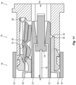
- the shutter system 100 includes a fiber optic connector shutter 110 and an adapter shutter 112.
- the fiber optic connector shutter 110 engages the adapter shutter 112 as the fiberoptic connector 102 is inserted into the adapter 104.
- the two shutters move together, preferably about a common axis, thereby locking dust and debris therebetween, which are pushed out of the way by the fiber optic connector 102 as it is inserted into the adapter 104.
- the fiber optic connector 102 includes an outer housing 120 and an inner housing 122 that contains a fiber optic ferrule 124. See, e.g. Fig. 2 .
- the fiber optic ferrule 124 holds the optical fibers 126, which are secured therein.
- the fiber optic connector 102 also includes a shroud 128 that is disposed between the outer housing 120 and the inner housing 122.
- the fiber optic connector 102 may include other parts that are not explicitly illustrated or discussed herein. For example, there may be a spring to bias the fiber optic ferrule 124, a spring push, a crimp body, etc.
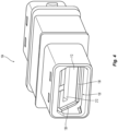
- the adapter 104 has an opening 130 at the front end 132 to receive the fiber optic connector 102.
- a second fiber optic connector may be inserted into the adapter 104 from an opposite end to mate with the fiber optic connector 102.
- the adapter 104 may also include a chamfered front portion 134 to assist in aligning the fiber optic connector 102 with the adapter 104.
- the chamfered front portion 134 may be removable (using tabs 136 to connect with the adapter 104), permanently attached, or integral with the remainder of the adapter 104.
- the adapter 104 may have other structures that assist in the mating of the fiber optic connector 102 with the adapter 104.
- adapter stop surfaces 138 in the opening 130 of the adapter 104 (see, e.g., Figs. 1 , 2 , and 5 ), guide pins 140 ( Fig. 2 ), and/or other alignment and stop features.
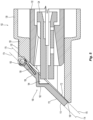
- the shroud 128 has shroud pivot sleeves 142, preferably two shroud pivot sleeves 142, that are spaced apart. There are also shutter pivot sleeves 144 on the fiber optic connector shutter 110 that are also spaced apart, the shroud pivot sleeves 142 being disposed between the two shutter pivot sleeves 144. However, it is also possible that the shutter pivot sleeves 144 are between the shroud pivot sleeves 142.
- a pin 146 passes through openings 148 of the sleeves, 142,144 and defines a first axis A of rotation for the fiber optic connector shutter 110 on the shroud 128.
- a spring element 150 is disposed around the pin 146 and engages a shroud tab 152 with one end 154 thereof and the second end 156 of the spring element 150 is inserted into a shutter door opening 158 ( Fig. 5 ) on the fiber optic connector shutter 110. It should be understood that other spring elements 150 could be used and could engage the shroud 128 and the fiber optic connector shutter 110 in other ways and still fall within the scope of the present invention.
- the shroud 128 has a front face 160 that surrounds the shroud 128.
- the front face 160 also functions as stop surface and as a fiber optic connector shutter 110 stop surface as well.
- the front face 160 of the shroud 128 is at an angle of about 45 degrees to an axis through the fiber optic connector 102 (along the optical fibers 126) but could be disposed at other angles as well.
- the fiber optic connector shutter 110 rests on the front face 160 when disengaged from the adapter 104.
- This arrangement provides the dust and debris elimination function for the fiber optic connector 102. Any dust or debris that falls on the fiber optic connector 102 or on the fiber optic connector shutter 110 does not end up on the end face of the fiber optic ferrule 124.
- the front face 160 also engages the adapter stop surfaces 138 in the opening 130 when the fiber optic connector 102 is inserted into the adapter 104. See, e.g., Fig. 2 . This will be described in more detail below.
- the fiber optic connector shutter 110 has an outer surface 170 and an inner surface 172.
- the majority of the outer surface 170 lies in an outer surface plane 174, while the majority of the inner surface 172 lies in an inner surface plane 176.
- the shutter door opening 158 for the spring element 150 may provide some structure that prevents it from lying in the outer surface plane 174.
- the majority of the inner surface 172 lies on the inner surface plane 176, there may also be pads 178 on the inner surface 172 that extend away from the inner surface 172. The pads 178 are used by the fiber optic connector 102 during insertion into the adapter to rotate the fiber optic connector shutter 110 out of the way of the fiber optic ferrule 124.
- a notch 190 on the fiber optic connector shutter 110 is a notch 190 on the fiber optic connector shutter 110.
- the notch 190 will engage a similar structure on the adapter shutter 112 to move in unison and to capture the dust and debris therebetween.
- the notch 190 has an outer portion 192 extending forward from the outer surface 170 and beyond the outer surface plane 174.
- the notch 190 also has a corresponding inner indentation 194 extending into the fiber optic connector shutter 110 forward of the inner surface plane 176.
- the inner indentation 194 corresponds to a front portion of the fiber optic ferrule 124.
- the fiber optic connector 102 when the fiber optic connector 102 is inserted into the adapter 104, an upper portion of the inner housing 122 engages the fiber optic connector shutter 110, and the pads 178 in particular and causes the fiber optic connector shutter 110 to rotate about the first axis A. See Figs. 9 and 10 .
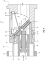
- the adapter shutter 112 has an outer surface 200 and an inner surface 202, the outer surface 200 has an outer surface plane 204 and the inner surface 202 has an inner surface plane 206.
- At the top of the adapter shutter 112 is generally circular pivot 208 that is disposed in a cavity in the adapter 104 and in the chamfered front portion 134 in particular.
- the generally circular pivot 208 rotates about a second axis B within the adapter 104.
- the generally circular pivot 208 has a groove 208A (see Figs. 7 and 8 ) to receive shroud pivot sleeves 140 and shutter pivot sleeves 142 of the fiber optic connector shutter 110.
- the adapter shutter 112 also has a notch 210 that has an indentation 212 extending from the outer surface 200 into the adapter shutter 112 rearwardly of the outer surface plane 204 and a corresponding inner projection 214 extending from the inner surface 202 rearwardly beyond the inner surface plane 206 and into the opening 130 of the adapter 104.
- the configuration of the indentation 212 corresponds to configuration of the notch 190 on the fiber optic connector shutter 110 and the outer portion 192 in particular. This allows the fiber optic connector shutter 110 and the adapter shutter 112 to nest and capture the dust and debris between the two shutters.
- the adapter 104 also includes a spring element 220, a torsion spring is illustrated but other resilient elements could be used, that has two arms 222,224 to bias the adapter shutter 112 in a closed position.
- the first arm 222 engages an inside surface 226 of the adapter 104, while the second arm 224 engages the projection 214 on the inner surface 202 of the adapter shutter 112.
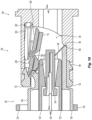
- the mating of the fiber optic connector 102 with the adapter 104 and the movement of the fiber optic connector shutter 110 and an adapter shutter 112 will be discussed with reference to Figs. 9-11 .
- the upper portion of inner housing 112 makes contact with the fiber optic connector shutter 110 and the pads 178 as shown in Fig. 9 .
- the fiber optic ferrule 124 is disposed within the inner indentation 194.
- the shroud 128 has made contact with the adapter stop surfaces 138, preventing the shroud 128 from moving forward and into the adapter 104 any farther.
- inner housing 122 in the fiber optic ferrule 124 can still move forward into the adapter 104.
- the shroud pivot sleeves 142 and the shutter pivots sleeves 144 have moved into the groove 208A of the circular pivot 208, thereby aligning first axis A with second axis B.
- the outer portion 192 of the notch 190 on fiber optic connector shutter 110 is disposed within the indentation 122 of the notch 210 of the adapter shutter 112.
- the two outer surfaces 170, 200 of the fiber optic connector shutter 110 and the adapter shutter 112, respectively, are adjacent to one another and in close proximity.
- the fiber optic connector shutter 110 and the adapter shutter 112 have space 230 where the dust and debris are captured during the insertion and removal of the fiber optic connector 102 from the adapter 104.
- the fiber optic connector shutter 110 and the adapter shutter 112 now rotate about a combined first axis A and second axis B that forms a rotation axis. It should be noted that the fiber optic connector shutter 110 and an adapter shutter 112 could have different configurations to allow for a larger and/or smaller space 230 therebetween.
- the fiber optic connector shutter 110 and an adapter shutter 112 could have separate axes of the rotation, but the fiber optic connector shutter 110 and an adapter shutter 112 should always move in unison with one another to prevent the dust and debris from contaminating a joining point or area of the fiber optic connectors 102.
- the fiber optic connector 102 has been inserted farther into the adapter 104.
- the fiber optic connector shutter 110 and an adapter shutter 112 continue to rotate about the rotation axis and up and out of the way of the inner housing 122 and fiber optic ferrule 124. It should be noted that while the fiber optic connector shutter 110 and an adapter shutter 112 are disposed on the top of the fiber optic connector 102 and the adapter 104, they can also be disposed on the bottom thereof.
- the inner housing 122 and fiber optic ferrule 124 have been inserted past the shutters 110,112 in Fig. 11 .
- the fiber optic ferrule 124 can now be mated with another fiber optic ferrule or optical component in a dust and debris-free environment.
- FIGs. 12A-12E Illustrated in Figs. 12A-12E is the progression of the insertion of the fiber optic connector 102 into the adapter 104 (or the unmating of the fiber optic connector 102 and the adapter 104 if viewed in reverse).
- the shroud 128 of fiber optic connectors 102 approach the ends of an adapter 104.
- the fiber optic connector shutters 110 and an adapter shutters 112 have engaged one another and the shrouds 128 have made contact with the adapter stop surfaces 138 in the adapter.
- the inner housings 122 have contacted the pads 178 on the inner surface 172 of the fiber optic connector shutters 110.
- Fig. 12A-12E Illustrated in Figs. 12A-12E is the progression of the insertion of the fiber optic connector 102 into the adapter 104 (or the unmating of the fiber optic connector 102 and the adapter 104 if viewed in reverse).
- the shroud 128 of fiber optic connectors 102 approach the ends of an adapter
- Fig. 12E shows the fiber optic connectors 102 are in a mated condition in a clean environment.
- shutters have been illustrated as moving and rotating towards the adapter, it is also possible that the shutters rotate towards the fiber optic connector as well.
Landscapes
- Physics & Mathematics (AREA)
- General Physics & Mathematics (AREA)
- Optics & Photonics (AREA)
- Mechanical Coupling Of Light Guides (AREA)
- Mechanical Light Control Or Optical Switches (AREA)
Claims (9)
- Connecteur de fibre optique (102), comprenant un boîtier externe (120), un embout de protection (128) disposé à l'extrémité avant du connecteur de fibre optique,un obturateur de connecteur de fibre optique (110) monté en rotation sur l'embout de protection autour d'un premier axe (A), l'obturateur de connecteur de fibre optique ayant une surface extérieure (107) et une surface intérieure (172), la surface extérieure ayant un plan de surface extérieure (174) et la surface intérieure ayant un plan de surface intérieure (176); etune encoche (190) dans l'obturateur de connecteur de fibre optique, l'encoche ayant une partie extérieure (192) s'étendant à l'avant depuis la surface extérieure au-delà du plan de surface extérieure et une indentation intérieure correspondante (194) s'étendant dans l'obturateur de connecteur de fibre optique à l'avant du plan de surface intérieure, etune ferrule de fibre optique (124) maintenant des fibres optiques (126),dans lequel le connecteur de fibre optique (102) comprend en outreun boîtier interne (122) qui contient la ferrule de fibre optique (124), et l'embout de protection (128) est disposé entre le boîtier externe (120) et le boîtier interne (122).
- Connecteur de fibre optique selon la revendication 1, dans lequel l'encoche (190) est configurée pour recevoir une partie d'une ferrule de fibre optique (124) à partir du connecteur de fibre optique (102) dans l'indentation intérieure (194).
- Connecteur de fibre optique selon la revendication 1, dans lequel l'embout de protection (128) a une surface de butée pour venir en prise avec une surface de butée (138) d'un adaptateur (104).
- Connecteur de fibre optique selon la revendication 1, dans lequel une partie du boîtier interne vient en prise avec l'obturateur de connecteur de fibre optique (110) pour faire pivoter l'obturateur de connecteur de fibre optique quand le boîtier de connecteur (120) se déplace par rapport à l'embout de protection (128).
- Connecteur de fibre optique selon la revendication 1, dans lequel l'embout de protection (128) comporte des fourreaux de pivot (142) et l'obturateur de connecteur de fibre optique (110) comporte des fourreaux de pivot (144), les fourreaux de pivot de l'embout de protection et les fourreaux de pivot de l'obturateur de connecteur de fibre optique recevant à travers ceux-ci une broche (146) pour attacher d'une façon permettant la rotation l'obturateur de connecteur de fibre optique (102) au connecteur de fibre optique sur un premier axe (A).
- Système constitué du connecteur de fibre optique selon la revendication 1 et d'un adaptateur (104), dans lequel l'encoche (190) dans l'obturateur de connecteur de fibre optique (110) vient en prise avec une partie d'un obturateur d'adaptateur (112) dans l'adaptateur (104) à l'intérieur duquel le connecteur de fibre optique (102) est inséré, dans lequel l'obturateur de connecteur de fibre optique (110) et l'obturateur d'adaptateur (112) pivotent autour du même axe lorsque le connecteur de fibre optique (102) est inséré dans l'adaptateur (104), et dans lequel l'obturateur de connecteur de fibre optique (110) et l'obturateur d'adaptateur (112) sont adjacents l'un à l'autre et se déplacent ensemble lorsque le connecteur de fibre optique (102) et l'adaptateur (104) sont accouplés.
- Système selon la revendication 6, dans lequel l'obturateur d'adaptateur (112) comporte une rainure (208A) pour recevoir les fourreaux de pivot (142) sur l'embout de protection et les fourreaux de pivot (144) sur l'obturateur de connecteur de fibre optique (110).
- Système selon la revendication 6, dans lequel l'obturateur d'adaptateur (112) comporte une encoche d'adaptateur (210) configurée pour recevoir au moins une partie de l'encoche dans l'obturateur de connecteur de fibre optique (110).
- Système selon la revendication 8, dans lequel l'obturateur d'adaptateur (112) comporte une surface extérieure (170) et une surface intérieure (172), la surface extérieure a un plan de surface extérieure (174) et la surface intérieure a un plan de surface intérieure (176), et
dans lequel l'encoche de l'obturateur d'adaptateur (210) comporte une indentation (194) s'étendant à l'arrière à partir de la surface extérieure à l'intérieur de l'obturateur d'adaptateur à l'arrière du plan de surface extérieure et une partie intérieure correspondante s'étendant à l'arrière à partir de la surface intérieure au-delà du plan de surface intérieure et à l'intérieur de l'adaptateur.
Priority Applications (1)
| Application Number | Priority Date | Filing Date | Title |
|---|---|---|---|
| EP24152140.0A EP4332651A2 (fr) | 2018-01-17 | 2019-01-17 | Connecteur de fibres optiques comprenant un obturateur |
Applications Claiming Priority (2)
| Application Number | Priority Date | Filing Date | Title |
|---|---|---|---|
| US201862618193P | 2018-01-17 | 2018-01-17 | |
| PCT/US2019/013957 WO2019143786A2 (fr) | 2018-01-17 | 2019-01-17 | Système d'obturateur à double verrouillage pour un connecteur et un adaptateur de fibre optique |
Related Child Applications (2)
| Application Number | Title | Priority Date | Filing Date |
|---|---|---|---|
| EP24152140.0A Division-Into EP4332651A2 (fr) | 2018-01-17 | 2019-01-17 | Connecteur de fibres optiques comprenant un obturateur |
| EP24152140.0A Division EP4332651A2 (fr) | 2018-01-17 | 2019-01-17 | Connecteur de fibres optiques comprenant un obturateur |
Publications (3)
| Publication Number | Publication Date |
|---|---|
| EP3740797A2 EP3740797A2 (fr) | 2020-11-25 |
| EP3740797A4 EP3740797A4 (fr) | 2021-09-22 |
| EP3740797B1 true EP3740797B1 (fr) | 2024-02-28 |
Family
ID=67301593
Family Applications (2)
| Application Number | Title | Priority Date | Filing Date |
|---|---|---|---|
| EP19741689.4A Active EP3740797B1 (fr) | 2018-01-17 | 2019-01-17 | Connecteur de fibre optique avec obturateur |
| EP24152140.0A Pending EP4332651A2 (fr) | 2018-01-17 | 2019-01-17 | Connecteur de fibres optiques comprenant un obturateur |
Family Applications After (1)
| Application Number | Title | Priority Date | Filing Date |
|---|---|---|---|
| EP24152140.0A Pending EP4332651A2 (fr) | 2018-01-17 | 2019-01-17 | Connecteur de fibres optiques comprenant un obturateur |
Country Status (4)
| Country | Link |
|---|---|
| US (3) | US11307360B2 (fr) |
| EP (2) | EP3740797B1 (fr) |
| CN (1) | CN111630422B (fr) |
| WO (1) | WO2019143786A2 (fr) |
Families Citing this family (4)
| Publication number | Priority date | Publication date | Assignee | Title |
|---|---|---|---|---|
| EP3698185A4 (fr) * | 2017-10-17 | 2021-07-14 | Commscope Technologies LLC | Configuration d'obturateur pour un port de connecteur de fibres optiques avec des supports de fibres modulaires ; et système de connexion |
| CN111630422B (zh) | 2018-01-17 | 2023-01-31 | 美国康涅克有限公司 | 用于光纤连接器及适配器的双互锁快门系统 |
| JP6724094B2 (ja) * | 2018-09-18 | 2020-07-15 | 株式会社フジクラ | 光コネクタシステム及びシャッター付き光コネクタ |
| US11815723B2 (en) | 2021-10-26 | 2023-11-14 | Sumitomo Electric Industries, Ltd. | Optical connection structure, optical connector, and optical connecting method |
Family Cites Families (19)
| Publication number | Priority date | Publication date | Assignee | Title |
|---|---|---|---|---|
| AU660859B2 (en) * | 1992-11-26 | 1995-07-06 | Diamond S.A. | Sleeve portion for an optical fibre plug connector |
| US5687268A (en) * | 1995-11-27 | 1997-11-11 | Lucent Technologies Inc. | Pivotable optical shutter for blocking emission from a lightguide adapter #5 |
| EP0800100A1 (fr) | 1996-04-04 | 1997-10-08 | US Conec Ltd | Assemblage d'embout pour l'insertion sans jeu d'une tige de guidage |
| US6039585A (en) * | 1997-03-10 | 2000-03-21 | Reynolds Industries Incorporated | Connector assembly with self activating environmental seal |
| US5883995A (en) * | 1997-05-20 | 1999-03-16 | Adc Telecommunications, Inc. | Fiber connector and adapter |
| US6142676A (en) | 1997-05-20 | 2000-11-07 | Adc Telecommunications, Inc. | Fiber connector and adaptor |
| EP0893716A1 (fr) * | 1997-07-21 | 1999-01-27 | Diamond S.A. | Douille en particulier pour une connexion optique et connecteur pour fibres optiques |
| US6081647A (en) | 1998-01-05 | 2000-06-27 | Molex Incorporated | Fiber optic connector receptacle |
| EP1072917A1 (fr) * | 1999-07-26 | 2001-01-31 | Diamond SA | Connecteur avec clapet de protection pour connexion à fibre optique |
| EP1271204B1 (fr) * | 2001-06-29 | 2005-03-23 | Diamond SA | Prise mâle et femelle pour un connecteur optique |
| AU2003203125A1 (en) | 2002-05-14 | 2003-11-11 | Huber+Suhner Ag | Optical connector |
| JP4327063B2 (ja) | 2004-10-26 | 2009-09-09 | 本多通信工業株式会社 | シャッター付き光コネクタ |
| US7785018B2 (en) | 2008-08-29 | 2010-08-31 | Corning Cable Systems Llc | Fiber optic adapters with integrated shutter |
| GB2506890B (en) * | 2012-10-10 | 2017-03-22 | Fibrefab Ltd | Fibre optic adaptor |
| US9798092B2 (en) | 2013-09-30 | 2017-10-24 | Hewlett Packard Enterprise Development Lp | Optical blind-mate connector and adapter |
| WO2015103726A1 (fr) * | 2014-01-07 | 2015-07-16 | 深圳日海通讯技术股份有限公司 | Connecteur de fibre optique |
| TWI608261B (zh) | 2016-11-29 | 2017-12-11 | 普泰光電股份有限公司 | 具有遮蔽件之光纖適配器 |
| CN111630422B (zh) | 2018-01-17 | 2023-01-31 | 美国康涅克有限公司 | 用于光纤连接器及适配器的双互锁快门系统 |
| JP6724094B2 (ja) | 2018-09-18 | 2020-07-15 | 株式会社フジクラ | 光コネクタシステム及びシャッター付き光コネクタ |
-
2019
- 2019-01-17 CN CN201980009031.4A patent/CN111630422B/zh active Active
- 2019-01-17 WO PCT/US2019/013957 patent/WO2019143786A2/fr unknown
- 2019-01-17 US US16/961,511 patent/US11307360B2/en active Active
- 2019-01-17 EP EP19741689.4A patent/EP3740797B1/fr active Active
- 2019-01-17 EP EP24152140.0A patent/EP4332651A2/fr active Pending
-
2022
- 2022-04-18 US US17/723,223 patent/US11822130B2/en active Active
-
2023
- 2023-11-20 US US18/514,221 patent/US20240094473A1/en active Pending
Also Published As
| Publication number | Publication date |
|---|---|
| WO2019143786A2 (fr) | 2019-07-25 |
| US11822130B2 (en) | 2023-11-21 |
| WO2019143786A3 (fr) | 2019-08-29 |
| US20200341209A1 (en) | 2020-10-29 |
| US20240094473A1 (en) | 2024-03-21 |
| CN111630422A (zh) | 2020-09-04 |
| US11307360B2 (en) | 2022-04-19 |
| EP3740797A4 (fr) | 2021-09-22 |
| EP4332651A2 (fr) | 2024-03-06 |
| CN111630422B (zh) | 2023-01-31 |
| EP3740797A2 (fr) | 2020-11-25 |
| US20220244466A1 (en) | 2022-08-04 |
Similar Documents
| Publication | Publication Date | Title |
|---|---|---|
| EP3740797B1 (fr) | Connecteur de fibre optique avec obturateur | |
| KR101607906B1 (ko) | 셔터 달린 lc 어댑터 | |
| EP0613030B1 (fr) | Connecteur fibre-optique | |
| JP5559863B2 (ja) | プッシュ−プッシュ式の挿入/引抜き機構、シャッターモジュラーコネクタおよびシャッターアダプタを有する超小型フォームファクターの単芯光ファイバ相互接続システム、並びにその使用方法 | |
| JP6400892B2 (ja) | Lc形光コネクタの防塵シャッタ内蔵アダプタ | |
| US6688780B2 (en) | Cantilevered shutter for optical adapter | |
| JP2001296453A (ja) | アダプタ | |
| US20090028507A1 (en) | Fiber optic adapter with integrated shutter | |
| CA2593819A1 (fr) | Systeme d'interconnexion a monofibre optique et facteur de forme tres compact, dote d'un mecanisme d'insertion/retrait du type a poussoir, d'un connecteur modulaire a obturateur et d'un adaptateur a obturateur, et procede d'utilisation du systeme | |
| JP6038666B2 (ja) | Lc形光コネクタ相互接続用アダプタ | |
| KR19990067932A (ko) | 광섬유 커넥터 리셉터클 | |
| US11086083B2 (en) | Optical connector with dust ingress mitigating cover | |
| EP0962799A2 (fr) | Connecteur optique avec volet d'obturation | |
| US20210231884A1 (en) | Optical connector | |
| JP6724094B2 (ja) | 光コネクタシステム及びシャッター付き光コネクタ | |
| US10444441B1 (en) | Pivotable housing for a fiber optic connector | |
| JP2022547821A (ja) | 光ファイバコネクタおよび光ファイバ接続システム | |
| JP2011150260A (ja) | 光コネクタ及びその組立方法 | |
| CA2594549A1 (fr) | Systeme d'interconnexion a fibres optiques multiples dote d'un mecanisme d'insertion/retrait du type a poussoir, d'un connecteur du type mt et d'un adaptateur a obturateur, et procede d'utilisation du systeme | |
| JPH10300985A (ja) | 多心光コネクタ | |
| EP3028080A1 (fr) | Sous-ensembles de connecteur de fibres optiques ayant un organe de maintien de ferrule à verrouillage à chargement par l'avant et composants de fibre optique, dispositifs et procédés associés |
Legal Events
| Date | Code | Title | Description |
|---|---|---|---|
| STAA | Information on the status of an ep patent application or granted ep patent |
Free format text: STATUS: THE INTERNATIONAL PUBLICATION HAS BEEN MADE |
|
| PUAI | Public reference made under article 153(3) epc to a published international application that has entered the european phase |
Free format text: ORIGINAL CODE: 0009012 |
|
| STAA | Information on the status of an ep patent application or granted ep patent |
Free format text: STATUS: REQUEST FOR EXAMINATION WAS MADE |
|
| 17P | Request for examination filed |
Effective date: 20200813 |
|
| AK | Designated contracting states |
Kind code of ref document: A2 Designated state(s): AL AT BE BG CH CY CZ DE DK EE ES FI FR GB GR HR HU IE IS IT LI LT LU LV MC MK MT NL NO PL PT RO RS SE SI SK SM TR |
|
| AX | Request for extension of the european patent |
Extension state: BA ME |
|
| DAV | Request for validation of the european patent (deleted) | ||
| DAX | Request for extension of the european patent (deleted) | ||
| REG | Reference to a national code |
Ref country code: DE Ref legal event code: R079 Ref document number: 602019047327 Country of ref document: DE Free format text: PREVIOUS MAIN CLASS: G02B0006245000 Ipc: G02B0006380000 Ref country code: DE Ref legal event code: R079 Free format text: PREVIOUS MAIN CLASS: G02B0006245000 Ipc: G02B0006380000 |
|
| A4 | Supplementary search report drawn up and despatched |
Effective date: 20210819 |
|
| RIC1 | Information provided on ipc code assigned before grant |
Ipc: G02B 6/38 20060101AFI20210813BHEP |
|
| GRAP | Despatch of communication of intention to grant a patent |
Free format text: ORIGINAL CODE: EPIDOSNIGR1 |
|
| STAA | Information on the status of an ep patent application or granted ep patent |
Free format text: STATUS: GRANT OF PATENT IS INTENDED |
|
| INTG | Intention to grant announced |
Effective date: 20230915 |
|
| GRAS | Grant fee paid |
Free format text: ORIGINAL CODE: EPIDOSNIGR3 |
|
| GRAA | (expected) grant |
Free format text: ORIGINAL CODE: 0009210 |
|
| STAA | Information on the status of an ep patent application or granted ep patent |
Free format text: STATUS: THE PATENT HAS BEEN GRANTED |
|
| P01 | Opt-out of the competence of the unified patent court (upc) registered |
Effective date: 20231222 |
|
| AK | Designated contracting states |
Kind code of ref document: B1 Designated state(s): AL AT BE BG CH CY CZ DE DK EE ES FI FR GB GR HR HU IE IS IT LI LT LU LV MC MK MT NL NO PL PT RO RS SE SI SK SM TR |
|
| REG | Reference to a national code |
Ref country code: GB Ref legal event code: FG4D |
|
| REG | Reference to a national code |
Ref country code: CH Ref legal event code: EP |
|
| REG | Reference to a national code |
Ref country code: DE Ref legal event code: R096 Ref document number: 602019047327 Country of ref document: DE |
|
| REG | Reference to a national code |
Ref country code: IE Ref legal event code: FG4D |