EP3740428B1 - An unmanned aerial vehicle - Google Patents
An unmanned aerial vehicle Download PDFInfo
- Publication number
- EP3740428B1 EP3740428B1 EP19704894.5A EP19704894A EP3740428B1 EP 3740428 B1 EP3740428 B1 EP 3740428B1 EP 19704894 A EP19704894 A EP 19704894A EP 3740428 B1 EP3740428 B1 EP 3740428B1
- Authority
- EP
- European Patent Office
- Prior art keywords
- battery
- arm
- aerial vehicle
- unmanned aerial
- backbone
- Prior art date
- Legal status (The legal status is an assumption and is not a legal conclusion. Google has not performed a legal analysis and makes no representation as to the accuracy of the status listed.)
- Active
Links
Images


Classifications
-
- B—PERFORMING OPERATIONS; TRANSPORTING
- B64—AIRCRAFT; AVIATION; COSMONAUTICS
- B64C—AEROPLANES; HELICOPTERS
- B64C29/00—Aircraft capable of landing or taking-off vertically, e.g. vertical take-off and landing [VTOL] aircraft
- B64C29/0008—Aircraft capable of landing or taking-off vertically, e.g. vertical take-off and landing [VTOL] aircraft having its flight directional axis horizontal when grounded
- B64C29/0016—Aircraft capable of landing or taking-off vertically, e.g. vertical take-off and landing [VTOL] aircraft having its flight directional axis horizontal when grounded the lift during taking-off being created by free or ducted propellers or by blowers
- B64C29/0033—Aircraft capable of landing or taking-off vertically, e.g. vertical take-off and landing [VTOL] aircraft having its flight directional axis horizontal when grounded the lift during taking-off being created by free or ducted propellers or by blowers the propellers being tiltable relative to the fuselage
-
- B—PERFORMING OPERATIONS; TRANSPORTING
- B64—AIRCRAFT; AVIATION; COSMONAUTICS
- B64U—UNMANNED AERIAL VEHICLES [UAV]; EQUIPMENT THEREFOR
- B64U20/00—Constructional aspects of UAVs
- B64U20/50—Foldable or collapsible UAVs
-
- B—PERFORMING OPERATIONS; TRANSPORTING
- B64—AIRCRAFT; AVIATION; COSMONAUTICS
- B64U—UNMANNED AERIAL VEHICLES [UAV]; EQUIPMENT THEREFOR
- B64U10/00—Type of UAV
- B64U10/10—Rotorcrafts
- B64U10/13—Flying platforms
- B64U10/14—Flying platforms with four distinct rotor axes, e.g. quadcopters
-
- B—PERFORMING OPERATIONS; TRANSPORTING
- B60—VEHICLES IN GENERAL
- B60L—PROPULSION OF ELECTRICALLY-PROPELLED VEHICLES; SUPPLYING ELECTRIC POWER FOR AUXILIARY EQUIPMENT OF ELECTRICALLY-PROPELLED VEHICLES; ELECTRODYNAMIC BRAKE SYSTEMS FOR VEHICLES IN GENERAL; MAGNETIC SUSPENSION OR LEVITATION FOR VEHICLES; MONITORING OPERATING VARIABLES OF ELECTRICALLY-PROPELLED VEHICLES; ELECTRIC SAFETY DEVICES FOR ELECTRICALLY-PROPELLED VEHICLES
- B60L50/00—Electric propulsion with power supplied within the vehicle
- B60L50/50—Electric propulsion with power supplied within the vehicle using propulsion power supplied by batteries or fuel cells
- B60L50/60—Electric propulsion with power supplied within the vehicle using propulsion power supplied by batteries or fuel cells using power supplied by batteries
- B60L50/64—Constructional details of batteries specially adapted for electric vehicles
-
- B—PERFORMING OPERATIONS; TRANSPORTING
- B60—VEHICLES IN GENERAL
- B60L—PROPULSION OF ELECTRICALLY-PROPELLED VEHICLES; SUPPLYING ELECTRIC POWER FOR AUXILIARY EQUIPMENT OF ELECTRICALLY-PROPELLED VEHICLES; ELECTRODYNAMIC BRAKE SYSTEMS FOR VEHICLES IN GENERAL; MAGNETIC SUSPENSION OR LEVITATION FOR VEHICLES; MONITORING OPERATING VARIABLES OF ELECTRICALLY-PROPELLED VEHICLES; ELECTRIC SAFETY DEVICES FOR ELECTRICALLY-PROPELLED VEHICLES
- B60L50/00—Electric propulsion with power supplied within the vehicle
- B60L50/50—Electric propulsion with power supplied within the vehicle using propulsion power supplied by batteries or fuel cells
- B60L50/60—Electric propulsion with power supplied within the vehicle using propulsion power supplied by batteries or fuel cells using power supplied by batteries
- B60L50/66—Arrangements of batteries
-
- B—PERFORMING OPERATIONS; TRANSPORTING
- B60—VEHICLES IN GENERAL
- B60L—PROPULSION OF ELECTRICALLY-PROPELLED VEHICLES; SUPPLYING ELECTRIC POWER FOR AUXILIARY EQUIPMENT OF ELECTRICALLY-PROPELLED VEHICLES; ELECTRODYNAMIC BRAKE SYSTEMS FOR VEHICLES IN GENERAL; MAGNETIC SUSPENSION OR LEVITATION FOR VEHICLES; MONITORING OPERATING VARIABLES OF ELECTRICALLY-PROPELLED VEHICLES; ELECTRIC SAFETY DEVICES FOR ELECTRICALLY-PROPELLED VEHICLES
- B60L58/00—Methods or circuit arrangements for monitoring or controlling batteries or fuel cells, specially adapted for electric vehicles
- B60L58/10—Methods or circuit arrangements for monitoring or controlling batteries or fuel cells, specially adapted for electric vehicles for monitoring or controlling batteries
-
- B—PERFORMING OPERATIONS; TRANSPORTING
- B64—AIRCRAFT; AVIATION; COSMONAUTICS
- B64D—EQUIPMENT FOR FITTING IN OR TO AIRCRAFT; FLIGHT SUITS; PARACHUTES; ARRANGEMENT OR MOUNTING OF POWER PLANTS OR PROPULSION TRANSMISSIONS IN AIRCRAFT
- B64D27/00—Arrangement or mounting of power plants in aircraft; Aircraft characterised by the type or position of power plants
- B64D27/40—Arrangements for mounting power plants in aircraft
- B64D27/402—Arrangements for mounting power plants in aircraft comprising box like supporting frames, e.g. pylons or arrangements for embracing the power plant
-
- B—PERFORMING OPERATIONS; TRANSPORTING
- B64—AIRCRAFT; AVIATION; COSMONAUTICS
- B64U—UNMANNED AERIAL VEHICLES [UAV]; EQUIPMENT THEREFOR
- B64U20/00—Constructional aspects of UAVs
- B64U20/80—Arrangement of on-board electronics, e.g. avionics systems or wiring
- B64U20/87—Mounting of imaging devices, e.g. mounting of gimbals
-
- B—PERFORMING OPERATIONS; TRANSPORTING
- B64—AIRCRAFT; AVIATION; COSMONAUTICS
- B64U—UNMANNED AERIAL VEHICLES [UAV]; EQUIPMENT THEREFOR
- B64U30/00—Means for producing lift; Empennages; Arrangements thereof
- B64U30/20—Rotors; Rotor supports
- B64U30/29—Constructional aspects of rotors or rotor supports; Arrangements thereof
- B64U30/293—Foldable or collapsible rotors or rotor supports
-
- B—PERFORMING OPERATIONS; TRANSPORTING
- B64—AIRCRAFT; AVIATION; COSMONAUTICS
- B64U—UNMANNED AERIAL VEHICLES [UAV]; EQUIPMENT THEREFOR
- B64U50/00—Propulsion; Power supply
- B64U50/10—Propulsion
- B64U50/13—Propulsion using external fans or propellers
-
- B—PERFORMING OPERATIONS; TRANSPORTING
- B64—AIRCRAFT; AVIATION; COSMONAUTICS
- B64U—UNMANNED AERIAL VEHICLES [UAV]; EQUIPMENT THEREFOR
- B64U50/00—Propulsion; Power supply
- B64U50/10—Propulsion
- B64U50/19—Propulsion using electrically powered motors
-
- H—ELECTRICITY
- H01—ELECTRIC ELEMENTS
- H01M—PROCESSES OR MEANS, e.g. BATTERIES, FOR THE DIRECT CONVERSION OF CHEMICAL ENERGY INTO ELECTRICAL ENERGY
- H01M50/00—Constructional details or processes of manufacture of the non-active parts of electrochemical cells other than fuel cells, e.g. hybrid cells
- H01M50/20—Mountings; Secondary casings or frames; Racks, modules or packs; Suspension devices; Shock absorbers; Transport or carrying devices; Holders
-
- B—PERFORMING OPERATIONS; TRANSPORTING
- B60—VEHICLES IN GENERAL
- B60L—PROPULSION OF ELECTRICALLY-PROPELLED VEHICLES; SUPPLYING ELECTRIC POWER FOR AUXILIARY EQUIPMENT OF ELECTRICALLY-PROPELLED VEHICLES; ELECTRODYNAMIC BRAKE SYSTEMS FOR VEHICLES IN GENERAL; MAGNETIC SUSPENSION OR LEVITATION FOR VEHICLES; MONITORING OPERATING VARIABLES OF ELECTRICALLY-PROPELLED VEHICLES; ELECTRIC SAFETY DEVICES FOR ELECTRICALLY-PROPELLED VEHICLES
- B60L2200/00—Type of vehicles
- B60L2200/10—Air crafts
-
- B—PERFORMING OPERATIONS; TRANSPORTING
- B64—AIRCRAFT; AVIATION; COSMONAUTICS
- B64U—UNMANNED AERIAL VEHICLES [UAV]; EQUIPMENT THEREFOR
- B64U30/00—Means for producing lift; Empennages; Arrangements thereof
- B64U30/20—Rotors; Rotor supports
- B64U30/29—Constructional aspects of rotors or rotor supports; Arrangements thereof
-
- B—PERFORMING OPERATIONS; TRANSPORTING
- B64—AIRCRAFT; AVIATION; COSMONAUTICS
- B64U—UNMANNED AERIAL VEHICLES [UAV]; EQUIPMENT THEREFOR
- B64U60/00—Undercarriages
- B64U60/50—Undercarriages with landing legs
-
- H—ELECTRICITY
- H01—ELECTRIC ELEMENTS
- H01M—PROCESSES OR MEANS, e.g. BATTERIES, FOR THE DIRECT CONVERSION OF CHEMICAL ENERGY INTO ELECTRICAL ENERGY
- H01M2220/00—Batteries for particular applications
- H01M2220/20—Batteries in motive systems, e.g. vehicle, ship, plane
-
- Y—GENERAL TAGGING OF NEW TECHNOLOGICAL DEVELOPMENTS; GENERAL TAGGING OF CROSS-SECTIONAL TECHNOLOGIES SPANNING OVER SEVERAL SECTIONS OF THE IPC; TECHNICAL SUBJECTS COVERED BY FORMER USPC CROSS-REFERENCE ART COLLECTIONS [XRACs] AND DIGESTS
- Y02—TECHNOLOGIES OR APPLICATIONS FOR MITIGATION OR ADAPTATION AGAINST CLIMATE CHANGE
- Y02E—REDUCTION OF GREENHOUSE GAS [GHG] EMISSIONS, RELATED TO ENERGY GENERATION, TRANSMISSION OR DISTRIBUTION
- Y02E60/00—Enabling technologies; Technologies with a potential or indirect contribution to GHG emissions mitigation
- Y02E60/10—Energy storage using batteries
-
- Y—GENERAL TAGGING OF NEW TECHNOLOGICAL DEVELOPMENTS; GENERAL TAGGING OF CROSS-SECTIONAL TECHNOLOGIES SPANNING OVER SEVERAL SECTIONS OF THE IPC; TECHNICAL SUBJECTS COVERED BY FORMER USPC CROSS-REFERENCE ART COLLECTIONS [XRACs] AND DIGESTS
- Y02—TECHNOLOGIES OR APPLICATIONS FOR MITIGATION OR ADAPTATION AGAINST CLIMATE CHANGE
- Y02T—CLIMATE CHANGE MITIGATION TECHNOLOGIES RELATED TO TRANSPORTATION
- Y02T10/00—Road transport of goods or passengers
- Y02T10/60—Other road transportation technologies with climate change mitigation effect
- Y02T10/70—Energy storage systems for electromobility, e.g. batteries
-
- Y—GENERAL TAGGING OF NEW TECHNOLOGICAL DEVELOPMENTS; GENERAL TAGGING OF CROSS-SECTIONAL TECHNOLOGIES SPANNING OVER SEVERAL SECTIONS OF THE IPC; TECHNICAL SUBJECTS COVERED BY FORMER USPC CROSS-REFERENCE ART COLLECTIONS [XRACs] AND DIGESTS
- Y02—TECHNOLOGIES OR APPLICATIONS FOR MITIGATION OR ADAPTATION AGAINST CLIMATE CHANGE
- Y02T—CLIMATE CHANGE MITIGATION TECHNOLOGIES RELATED TO TRANSPORTATION
- Y02T50/00—Aeronautics or air transport
- Y02T50/60—Efficient propulsion technologies, e.g. for aircraft
Definitions
- the present invention relates to an unmanned aerial vehicle (UAV), as specified in the accompanying patent claims.
- UAV unmanned aerial vehicle
- WO 2008/147484 A2 describes a modular vehicle having an air vehicle that can be coupled to cargo containers, land vehicles, sea vehicles, medical transport modules, etc.
- the air vehicle has a plurality of propellers positioned around a main airframe, which can provide vertical thrust and/or horizontal thrust.
- One or more of the propellers may be configured to tilt forward, backward, and/or side-to-side with respect to the airframe.
- the prior art also includes KR 10-1527544 B1 , which describes a drone which can reduce its volume when it is not in use.
- the drone airframe has an oblong shape, and the drone arms (to which the rotors are mounted) are pivotable to fold along the airframe.
- the width of the frontal part of the airframe is greater than that of the rear part, thereby allowing the front and rear arms to be folded side-by-side, and not overlapping with each other.
- the prior art also includes WO 2017/185487 A1 , which describes a battery fixing and mounting structure for a battery self-dismounting unmanned aerial vehicle, comprising an unmanned aerial vehicle mainly body and a battery cover.
- a battery chamber used for accommodating a battery is formed in the bottom of the unmanned aerial vehicle mainly body.
- a hinged connection hole is formed in one side of the battery chamber.
- a hinged connection pillar matching the hinged connection hole is disposed on one corresponding side on the battery cover. The hinged connection pillar is hingedly connected in the hinged connection hole and enables the battery cover to be hingedly connected onto the unmanned aerial vehicle mainly body.
- An object of the present invention is to provide a highly reliable and long-term stable rotor-wing multicopter type and rapidly deployable aerial vehicle with a plurality of motors, advantageously operable as a drone, and designed to carry heavy cargo loads, fixed to the fuselage or connected to the drone by slings.
- the loads may be in a range from about 5kg to about 500kg.
- a rapidly deployable aerial vehicle having a rotating wing lift generating means advantageously a rapidly deployable unmanned aerial vehicle (UAV), such as rapidly deployable unmanned multicopter, embodied with a unitary main fuselage and advantageously embodied with a swingable arm mount as illustrated and described herein, exhibits advantageous properties and capabilities that makes it highly desirable for use in applications where a manned aircraft, such as a manned airplane or a manned helicopter, involves high risk or high cost on personnel or equipment or meets other substantial limitations on its operation that prohibits its use, in particular in an emergency situation under adverse operating conditions.
- the apparatus of the present invention in particular capable of providing fast deployment and be ready for action in a matter of minutes with a stability that remains substantially unchanged over time.
- an unmanned aerial vehicle having a main body comprising at least an elongate main frame, also referred to as a backbone, with a forward end piece and a rearward end piece, said end pieces being wider than the backbone and comprising coupling facilities for respective rotor arms, each said rotor arm configured for supporting motor and propeller assemblies;
- the unmanned aerial vehicle further comprises a pair of elongated batteries; the end pieces and at least a portion of the backbone form receptacles on both sides of the backbone for releasably receiving respective electric batteries, wherein the batteries, backbone and end pieces form an elongate and substantially rectangular body assembly.
- each rotor arm comprises an arm inner part having on one end a coupling arrangement adapted for coupling to respective end pieces of the main body and on a second end a first part of an arm folding hinge, and an arm outer part having on one end an adapter for said motor and propeller assemblies and on a second end a second part of the arm folding hinge, and a displace
- the invention provides a swingable arm mount for an aerial vehicle having a lift generating means, the aerial vehicle being advantageously a multicopter.
- an example concerns an unmanned multicopter having a main body comprising
- the assembly comprising a complete rotor arm and a rotor assembly comprising motor mount, motors and propellers is frequently referred to as the "arm”.
- the drone body comprising a main frame (commonly referred to as a “backbone”), end pieces, end caps and components mounted thereon, but without the batteries, arms and undercarriage, is frequently referred to as the "body”.
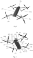
- FIG. 1 shows main assemblies and components such as the body 100 with a pair of batteries 500 mounted thereon, so as to form an elongate and substantially rectangular body assembly.
- Figure 2 shows components and sub-assemblies of the body 100, such as a forward endcap 110 with sensor windows 111, an optional forward adapter plate 120, a forward end piece 130, a backbone 140, a rearward end piece 150, an optional rearward adapter plate 160, a stern endcap 170, battery locking arrangements 190, components and subassemblies of the arms 200, such as arm inner part 210, arm outer part 220, and arm folding hinge locking arrangement 230, and components and subassemblies of the rotor assemblies 400, such as rotor mounts 410, upper motor and propeller assemblies 420A, and lower motor and propeller assemblies 420B.
- a forward endcap 110 with sensor windows 111 such as a forward endcap 110 with sensor windows 111, an optional forward adapter plate 120, a forward end piece 130, a backbone 140, a rearward end piece 150, an optional rearward adapter plate 160, a stern endcap 170, battery locking arrangements 190, components and subass
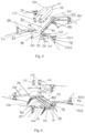
- Figures 3 and 4 show the body backbone 140 and forward shoulders 131 and 132, comprising adapters arranged on the forward end piece 130 arranged to provide for secure attachment of forward arms 200 to the body 100.
- the rearward end piece 150 includes rearward shoulders 151 and 152 comprising adapters arranged on the rearward end piece 150 arranged to provide for secure attachment of rearward arms 200 to the body 100.
- a battery connector 180 for electric connection is provided on at least one side of the backbone 140, adapted to provide electrical connection with a mating electrical connector 580 on the battery.
- Battery holding and locking means first parts 190 are disposed on respective ones of sides of the forward 130 and rearward 150 end pieces that are substantially perpendicular to a longitudinal axis of the body 100 and facing each other.
- Battery holding and locking means second parts 514 designed to cooperate and engage with the battery holding and locking means first parts 190, are disposed on respective ends of each battery 500.
- levers of the battery holding and locking means 190 are shown in a position for unlocking and releasing the batteries, and are seen as L-shaped elements protruding from lower edges of sides of the forward 130 and rearward 150 end pieces that are facing each other and are visible when batteries 500 are not installed between these sides on the body.
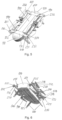
- FIGS 5 to 8 illustrating a rotor-wing multicopter according to the invention in a configuration with arms 200 folded against the body 100 and locked in a folded state, ready for storage or transportation.
- Figures 5 to 8 identify the lock slider 231 and the lock pin 232 of the arm folding hinge lock arrangement 230, the end portion 218 of the arm inner part 210 and the end portion 225 of the arm outer part 220 which both are of a shape that correspond to sections of a toroid, and the portion 215 of the arm inner part 210 and the portion 228 of the arm outer part 220 which are hollow toroidal sections and matchingly shaped to the end portions 225 and 218 so as to receive respective ones of the end portions 225 and 218, respectively, when the arm is rotated about the folding hinge from a folded to a deployed state.
- forces such as torque and shear acting around and across the longitudinal axis of the arm are coupled directly between inner and outer arm parts 210, 220 without stressing the hinge pin around which the arm outer part is rotated when
- Figure 8 also identifies a mounting track 145 in the unitary backbone 140 into which auxiliary equipment such as e.g. a camera foot may be mounted.
- auxiliary equipment such as e.g. a camera foot
- levers of the battery holding and locking means 190 are in position for locking and holding the batteries in place on the body, and that the L-shaped lever elements shown in figures 3 and 4 protruding from lower edges of sides of the forward 130 and rearward 150 end pieces are in figures 5 and 6 , as well as in figures 1 and 2 , positioned in recesses in the forward 130 and rearward 150 end pieces and substantially hidden between these and respective adjacent end sides 514 of the batteries when batteries 500 are fully installed on the body.
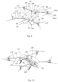
- Figure 9 shows elements and subassemblies of the body 100, such as bow end cap 110, optional forward adapter plate 120, forward end piece 130, body backbone 140 with electrical connector 180 for connecting to battery, rearward end piece 150 with parts of battery holding and locking arrangement 190, optional rearward adapter plate 160, and stern end cap 170, and elements and subassemblies of the rotor arm 200, such as arm inner part 210, arm folding hinge arrangement 230, and arm outer part 220, and elements and subassemblies of the rotors 400, such as motor mount 410, upper rotor assembly 420A, and lower rotor assembly 420B.
- the body 100 such as bow end cap 110, optional forward adapter plate 120, forward end piece 130, body backbone 140 with electrical connector 180 for connecting to battery, rearward end piece 150 with parts of battery holding and locking arrangement 190, optional rearward adapter plate 160, and stern end cap 170
- elements and subassemblies of the rotor arm 200 such as arm inner part 210
- Figure 10 illustrates and identifies the end portions 218 of the arm inner parts 210 and the end portions 225 of the arm outer parts 220 which are both of a shape that correspond to partial sections of a toroid, and the portions 215 of the arm inner parts 210 and the portions 228 of the arm outer parts 220 which are in part hollow toroidal like shaped sections, matchingly shaped as complements to the end portions 225 and 218, so as to be capable of receiving respective ones of the end portions 225 and 218, respectively, when the arm is rotated about the folding hinge from a folded to a deployed state.
- FIGS 11 and 12 illustrate and identify elements and sub-assemblies of battery locking means 190 parts to be disposed at a side of the forward 130 and rearward 150 end pieces of a multicopter embodiment of the aerial vehicle of the invention, and to figure 13 in which are illustrated and identified elements and sub-assemblies of battery holding and locking arrangement parts located at short sides 514 at ends of the elongate battery 500.
- Figures 11 and 12 illustrate and identify a rail 191, and a lever 192 with finger grab opening 196, lever rotation axis and bearing 195, carrier stud 193, and lever latching cam 194, and a lever latching pin and release button assembly 198.
- figure 13 illustrate and identifies features of battery 500 including a top long side 510, an inner long side 511, an outer long side 512, a bottom long side 513, and an end short side 514 of a battery 500, and on the end short side 514 comprising parts of the battery holding and locking means including a straight first recessed track 515 and an L-shaped second recessed track 516, both tracks having end openings at an edge of the bottom long side 513.
- the straight first recessed track 515 is dimensioned to receive at its opening the rail 191 to control the battery 500 to slide onto the body 100 and is positioned on the end short side 514 of the battery so as to position the battery next to a long side of the backbone 140 and position the electrical connector 580 of the battery in alignment with the electrical connector 180 of the body 100.
- the opening of the L-shaped second recessed track 516 is positioned on the end short side 514 of the battery so as to be capable of receiving the carrier stud 193 on the lever 192 positioned in the unlock and release position as illustrated in figure 11 .
- the corner of the L-shaped second recessed track 516 is positioned so as to meet the carrier stud 193 when the battery has sledded along the rail 191 till the point where the electrical connector 580 is about to make contact with the electrical connector 180, at which point the carrier stud 193 stops further movement of the battery until the lever is rotated about its rotation axis and bearing 195.
- the carrier stud 193 follows the circular path in an opposite direction, and limited by horizontal portion of the L-shaped second recessed track 516, the carrier stud 193 brings the battery 500 along and with leverage drives it to move further to a point at which the top 510 and bottom 513 long sides of the battery are elevated with respective top and bottom long sides of the backbone 140 and the electrical connector 580 of the battery is fully lifted out and disconnected to the electrical connector 180 of the body.
- the lever latching cam 194 contacts the spring biased lever latching pin of the lever latching pin and release button assembly 198, and displaces the lever latching pin until the lever is rotated to the point at which the lever latching pin drops into a recessed portion of the cam at a root of the cam, thereby latching the lever 192 secured in its position for holding and locking the battery 500 in place on the body 100.
- the displacement of the lever latching pin by the cam also displaces the release button of the lever latching pin and release button assembly 198 for the release button to be retracted into the respective end piece 130, 150.
- Sides of the release body that become hidden as the cam effects retraction of the release button are advantageously painted in a signal colour, thus providing when not retracted into the respective end piece a clearly visible signal of incorrectly positioned and non-latched lever.
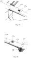
- FIGS 14 and 15 illustrate and identify in more detail forward 131 and rearward 151 shoulder portions of the forward 130 and rearward 150 end pieces that are adapted to receive and secure to the body 100 inner ends of arm inner parts 210, and constellation of arm inner parts 210, arm outer parts 220 and arm folding hinge arrangement 230 when arms 200 are fully unfolded and deployed ready for flight.
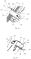
- FIGS 16 and 17 illustrate and identify in more detail forward 131 and rearward 151 shoulder portions of the forward 130 and rearward 150 end pieces that are adapted to receive and secure to the body 100 inner ends of arm inner parts 210, and constellation of arm inner parts 210, arm outer parts 220 and arm folding hinge arrangement 230 when arms 200 are fully folded in and ready for storage or transportation.
- locking means slider 231 operable to bring arm locking pin 232 in from its idle position at which it protrudes from an outer end of the arm inner part 210, and arm locking pin receiving opening 221 on the arm outer part 220 into which the arm locking pin 232 is protruding to secure the arm 200 in the fully unfolded and deployed ready for flight position.
- Figures 16 and 17 further illustrate release buttons fully retracted into respective end piece 130, 150, indicating levers 192 of the respective battery holding and locking means 190 are properly positioned to hold and lock battery 500.
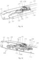
- FIGS. 18 and 19 illustrate and identify in more detail arm folding hinge and locking arrangements with rotor arms in the fully unfolded and deployed and locked in this position when ready for flight.
- Axis of rotation for the folding of arms 200 is defined by a hinge ring 235 which is attached to inner arm part 210 by ring mount 235A positioned within arm outer part 220.
- a ring shaped cavity of the arm inner part 210 forms a race for the hinge ring 235, thereby providing a hinge allowing the arm inner 210 and outer 220 parts to remain connected and rotatable with respect to each other in all positions from fully folded in to fully unfolded and deployed positions.
- Arm locking pin 232 is connected to slider 231, and springs 233 provides bias to the arm lock slider 231 so as to keep it in an idling position at which the arm locking pin 232 is protruding into arm locking opening 221 arranged in the arm outer part 220.
- An interlock button 231A is provided in the arm lock slider 231 to blocking of any inadvertent movement the slider 231 until unblocked by a pushing of the interlock button 231A.
- a locking cam 234 is connected to slider 231 and positioned for lodging into one of a plurality of locking slot 236 provided on the hinge ring 235. Thereby, locking cam 234 and locking slot 236 proved a further means for keeping the arm parts locked in position in the fully unfolded and deployed position.
- At least one locking slot 236 is provided at an angular position of the hinge ring for allowing the locking cam to be lodged in the locking slot when the arm is fully folded, thereby proving locking of an arm outer part relative to a respective arm inner part also in the folded position to block the arms from unfolding inadvertently, e.g. during handling for transportation, maintenance, storage or other situations.
- Figures 18 and 19 also show inner portion 211 of the arm inner parts 210, constituted by a tapered off section shaped to fit with a matchingly shaped tapered off opening in an end piece part of the body, such as e.g. shoulder 131, shoulder 132 and shoulder 151.
- the end portion 211 of the arm inner parts 210 has a cross section outline corresponding to the shape of a trapezium, with a cross section at a tip of the end portion 211 that is smaller than cross section further in from the tip.
- a UAV implementing the invention may be an embodiment in which only upper motor and propeller assemblies 420A or only lower motor and propeller assemblies 420B are included.
- motor supports may be oriented differently from what has been disclosed herein, and the arm parts may be of different design, although only one design has been shown to illustrate and explain the invention.
Landscapes
- Engineering & Computer Science (AREA)
- Mechanical Engineering (AREA)
- Aviation & Aerospace Engineering (AREA)
- Remote Sensing (AREA)
- Chemical & Material Sciences (AREA)
- Combustion & Propulsion (AREA)
- Sustainable Energy (AREA)
- Transportation (AREA)
- Power Engineering (AREA)
- Life Sciences & Earth Sciences (AREA)
- Sustainable Development (AREA)
- General Chemical & Material Sciences (AREA)
- Electrochemistry (AREA)
- Chemical Kinetics & Catalysis (AREA)
- Microelectronics & Electronic Packaging (AREA)
- Battery Mounting, Suspending (AREA)
- Air Bags (AREA)
- Forklifts And Lifting Vehicles (AREA)
Applications Claiming Priority (2)
| Application Number | Priority Date | Filing Date | Title |
|---|---|---|---|
| NO20180080A NO344274B1 (en) | 2018-01-17 | 2018-01-17 | An unmanned aerial vehicle having rotating wing lift generating means, advantageously a multicopter with a unitary main fuselage and foldable rotor arms. |
| PCT/NO2019/050008 WO2019143255A1 (en) | 2018-01-17 | 2019-01-17 | An unmanned aerial vehicle |
Publications (2)
| Publication Number | Publication Date |
|---|---|
| EP3740428A1 EP3740428A1 (en) | 2020-11-25 |
| EP3740428B1 true EP3740428B1 (en) | 2023-11-29 |
Family
ID=65409446
Family Applications (1)
| Application Number | Title | Priority Date | Filing Date |
|---|---|---|---|
| EP19704894.5A Active EP3740428B1 (en) | 2018-01-17 | 2019-01-17 | An unmanned aerial vehicle |
Country Status (11)
| Country | Link |
|---|---|
| US (1) | US11993373B2 (pl) |
| EP (1) | EP3740428B1 (pl) |
| JP (1) | JP7285847B2 (pl) |
| KR (1) | KR102652241B1 (pl) |
| CN (1) | CN111615488A (pl) |
| AU (1) | AU2019209760B2 (pl) |
| CA (1) | CA3088981A1 (pl) |
| ES (1) | ES2971586T3 (pl) |
| NO (1) | NO344274B1 (pl) |
| PL (1) | PL3740428T3 (pl) |
| WO (1) | WO2019143255A1 (pl) |
Families Citing this family (31)
| Publication number | Priority date | Publication date | Assignee | Title |
|---|---|---|---|---|
| CN112912310B (zh) * | 2018-09-11 | 2025-02-25 | 马克·霍尔布洛克·汉纳 | 具有分布式电池的运输飞行器及其供电方法 |
| CN114514417A (zh) * | 2019-10-11 | 2022-05-17 | 统治者视觉传播公司 | 水取样装置 |
| JP6976304B2 (ja) * | 2019-11-18 | 2021-12-08 | 株式会社NTT e−Drone Technology | 無人飛行体 |
| US20210214067A1 (en) * | 2020-01-13 | 2021-07-15 | Skydio, Inc. | Autonomous Unmanned Aerial Vehicle With Folding Collapsible Arms |
| DE102020104783A1 (de) * | 2020-02-24 | 2021-08-26 | Volocopter Gmbh | Batteriehaltevorrichtung, Batteriesystem, Fluggerät und Verfahren zum Wechseln einer Batterie für ein Fluggerät |
| WO2021230957A1 (en) * | 2020-05-14 | 2021-11-18 | Massachusetts Institute Of Technology | Aerial vehicle with tape spring arms |
| NO346040B1 (en) * | 2020-05-28 | 2022-01-17 | Griff Aviation As | A battery connector |
| KR102347832B1 (ko) * | 2020-07-02 | 2022-01-05 | 한국항공우주연구원 | 멀티콥터 |
| US20230278731A1 (en) * | 2020-09-03 | 2023-09-07 | Aerial Response Solutions, Llc ("Ars") | Airframe and motor assembly for an unmanned aircraft |
| WO2022058903A1 (fr) * | 2020-09-16 | 2022-03-24 | Dpendent - Drone Independent System Sàrl | Station logistique pour drones |
| CN112224396A (zh) * | 2020-10-20 | 2021-01-15 | 北京理工大学 | 机臂双层错列布置、可横向折叠的六旋翼无人机 |
| US11845544B2 (en) * | 2020-12-28 | 2023-12-19 | Textron Innovations, Inc. | Foldable aircraft |
| KR102314218B1 (ko) * | 2021-04-06 | 2021-10-18 | 주식회사 보라스카이 | 정찰용 접이식 드론 |
| DE102021110636A1 (de) * | 2021-04-26 | 2022-10-27 | Wingcopter GmbH | Fluggerät mit einem Batterieblock |
| GB2623016B (en) * | 2021-06-20 | 2024-08-21 | Norouzi Ramin | Reconfiguring vertical takeoff and landing aircraft |
| US12134466B2 (en) * | 2021-08-09 | 2024-11-05 | Insitu, Inc. | Unmanned aerial vehicles including wing capture devices and related methods |
| CN113415407B (zh) * | 2021-08-10 | 2022-11-29 | 珠海紫燕无人飞行器有限公司 | 一种可折叠无人机 |
| WO2023019404A1 (zh) * | 2021-08-16 | 2023-02-23 | 深圳市大疆创新科技有限公司 | 飞行器的机臂组件及飞行器 |
| US11970293B2 (en) * | 2022-03-26 | 2024-04-30 | Epazz, Inc. | Drone with extendable and rotatable wings and multiple accessory securing panel |
| CN114489145B (zh) * | 2022-04-13 | 2022-07-12 | 山东亿华天产业发展集团有限公司 | 无人机摄影测量路径规划方法及低空飞行无人机系统 |
| KR102804421B1 (ko) * | 2022-12-22 | 2025-05-13 | (주)프리뉴 | 드론 캐노피 |
| CN115924143B (zh) * | 2022-12-26 | 2025-05-06 | 中国兵器工业计算机应用技术研究所 | 一种可展收多旋翼无人机平台 |
| KR102789661B1 (ko) * | 2023-01-31 | 2025-04-03 | (주)프리뉴 | 폴딩 드론 |
| WO2024176845A1 (ja) * | 2023-02-20 | 2024-08-29 | ソニーグループ株式会社 | 飛行体 |
| CN116176896B (zh) * | 2023-03-27 | 2025-08-08 | 广州市华科尔科技股份有限公司 | 一种遥控消防直升飞机主体结构 |
| CN116280309A (zh) * | 2023-04-04 | 2023-06-23 | 威海广泰空港设备股份有限公司 | 大载重长航时多旋翼无人机 |
| CN116873248B (zh) * | 2023-07-18 | 2025-08-15 | 黑龙江惠达科技股份有限公司 | 无人机折叠机臂锁紧关节、机臂和无人机 |
| US20250153870A1 (en) * | 2023-11-15 | 2025-05-15 | Virginia Tech Intellectual Properties, Inc. | Novel extended range vertical take-off and landing drone |
| KR102671070B1 (ko) * | 2023-12-22 | 2024-05-30 | (주)프리뉴 | 모듈형 드론 |
| KR102712192B1 (ko) * | 2023-12-22 | 2024-09-27 | (주)프리뉴 | 수평 유지 드론 |
| US12176565B1 (en) * | 2024-02-27 | 2024-12-24 | Core SWX, LLC | Mounting system for a cinematography battery |
Family Cites Families (25)
| Publication number | Priority date | Publication date | Assignee | Title |
|---|---|---|---|---|
| US8453962B2 (en) * | 2007-02-16 | 2013-06-04 | Donald Orval Shaw | Modular flying vehicle |
| US8288035B2 (en) * | 2009-01-09 | 2012-10-16 | Electrochem Solutions, Inc. | Modular battery pack |
| US20140061376A1 (en) | 2010-05-26 | 2014-03-06 | Aerovironment Inc | Reconfigurable battery-operated vehicle system |
| US8774982B2 (en) * | 2010-08-26 | 2014-07-08 | Leptron Industrial Robotic Helicopters, Inc. | Helicopter with multi-rotors and wireless capability |
| KR101527544B1 (ko) * | 2015-01-10 | 2015-06-10 | 최종필 | 접이식 무인비행기 |
| US9409645B1 (en) * | 2015-03-02 | 2016-08-09 | Google, Inc. | Unmanned aerial vehicle for collaboration |
| US9738380B2 (en) * | 2015-03-16 | 2017-08-22 | XCraft Enterprises, LLC | Unmanned aerial vehicle with detachable computing device |
| KR101773674B1 (ko) * | 2015-09-10 | 2017-08-31 | 이미란 | 배터리 탈착 구조 및 이를 포함하는 드론 |
| US10807731B2 (en) * | 2015-09-25 | 2020-10-20 | Amazon Technologies, Inc. | Floating motor mount for unmanned aerial vehicles |
| WO2017131451A1 (ko) | 2016-01-26 | 2017-08-03 | 주식회사 아모그린텍 | 무인 비행 장치 |
| WO2017143501A1 (en) * | 2016-02-22 | 2017-08-31 | SZ DJI Technology Co., Ltd. | Foldable multi-rotor aerial vehicle |
| FR3048187A1 (fr) * | 2016-02-25 | 2017-09-01 | Parrot Drones | Drone muni d'un bloc batterie |
| US10870477B1 (en) * | 2016-04-05 | 2020-12-22 | Fpv Manuals Llc | Foldable arm mechanism for rotary wing aircraft |
| US10780970B2 (en) * | 2016-04-06 | 2020-09-22 | Harris Aerial Llc | Folding heavy-lift unmanned vehicle frame |
| KR102151787B1 (ko) * | 2016-04-27 | 2020-09-03 | 한화디펜스 주식회사 | 비행 이동 장치 |
| CN106564582B (zh) * | 2016-04-27 | 2022-06-24 | 北京远度互联科技有限公司 | 无人机 |
| CN205633009U (zh) * | 2016-04-28 | 2016-10-12 | 深圳市龙云创新航空科技有限公司 | 一种可自卸电池式无人机电池固定安装结构 |
| KR101919574B1 (ko) * | 2016-05-27 | 2018-11-19 | 주식회사 유비파이 | 무인항공기 |
| KR20170136309A (ko) * | 2016-06-01 | 2017-12-11 | 정명률 | 드론 |
| US10710701B2 (en) * | 2016-12-19 | 2020-07-14 | Haoxiang Electric Energy (Kunshan) Co., Ltd. | Foldable multi-rotor UAV |
| CN206476093U (zh) * | 2016-12-27 | 2017-09-08 | 歌尔科技有限公司 | 一种无人机 |
| CN106995052B (zh) | 2017-03-23 | 2020-01-24 | 沈阳无距科技有限公司 | 多轴无人机 |
| KR102323447B1 (ko) * | 2017-06-08 | 2021-11-08 | 삼성전자주식회사 | 가변형 무인비행체 |
| IL252808B2 (en) * | 2017-06-11 | 2023-06-01 | Spear U A V Ltd | Unmanned aircraft launched |
| FR3070607B1 (fr) * | 2017-09-07 | 2020-09-04 | Parrot Drones | Drone a voilure tournante comprenant une structure de drone pliable |
-
2018
- 2018-01-17 NO NO20180080A patent/NO344274B1/en unknown
-
2019
- 2019-01-17 KR KR1020207023562A patent/KR102652241B1/ko active Active
- 2019-01-17 US US16/962,491 patent/US11993373B2/en active Active
- 2019-01-17 CA CA3088981A patent/CA3088981A1/en active Pending
- 2019-01-17 PL PL19704894.5T patent/PL3740428T3/pl unknown
- 2019-01-17 JP JP2020539262A patent/JP7285847B2/ja active Active
- 2019-01-17 WO PCT/NO2019/050008 patent/WO2019143255A1/en not_active Ceased
- 2019-01-17 ES ES19704894T patent/ES2971586T3/es active Active
- 2019-01-17 EP EP19704894.5A patent/EP3740428B1/en active Active
- 2019-01-17 CN CN201980008757.6A patent/CN111615488A/zh active Pending
- 2019-01-17 AU AU2019209760A patent/AU2019209760B2/en active Active
Also Published As
| Publication number | Publication date |
|---|---|
| JP7285847B2 (ja) | 2023-06-02 |
| WO2019143255A1 (en) | 2019-07-25 |
| NO20180080A1 (en) | 2019-07-18 |
| KR20200106197A (ko) | 2020-09-11 |
| CN111615488A (zh) | 2020-09-01 |
| JP2021512002A (ja) | 2021-05-13 |
| NO344274B1 (en) | 2019-10-21 |
| AU2019209760B2 (en) | 2024-08-08 |
| EP3740428A1 (en) | 2020-11-25 |
| US20210078704A1 (en) | 2021-03-18 |
| ES2971586T3 (es) | 2024-06-06 |
| KR102652241B1 (ko) | 2024-03-28 |
| PL3740428T3 (pl) | 2024-04-22 |
| AU2019209760A1 (en) | 2020-09-03 |
| US11993373B2 (en) | 2024-05-28 |
| CA3088981A1 (en) | 2019-07-25 |
Similar Documents
| Publication | Publication Date | Title |
|---|---|---|
| EP3740428B1 (en) | An unmanned aerial vehicle | |
| US12139257B2 (en) | Air-launched unmanned aerial vehicle | |
| US11167848B2 (en) | Unmanned aerial vehicle with enhanced cargo storage | |
| US10399703B2 (en) | Articulated support for unmanned aircraft system | |
| US5779190A (en) | Portable unmanned aerial vehicle | |
| US7338010B2 (en) | Air-launchable aircraft and method of use | |
| US10549850B1 (en) | Portable multithruster unmanned aircraft | |
| KR101456035B1 (ko) | 멀티로터형 무인비행기의 로터암장치 | |
| US12583599B2 (en) | Connectors and joints for dual engine vertical take off and landing collapsible fixed wing aircraft | |
| BR102016022821B1 (pt) | Conjuntos e métodos para reconfigurar portas de fuselagem de aeronave | |
| WO2015115913A1 (en) | Multipurpose aircraft | |
| US12576997B2 (en) | Drone arm folding/locking mechanism | |
| US11702187B2 (en) | Collapsible pylons for drone aircraft | |
| CN115503934B (zh) | 用于箱式发射的固定翼无人机折叠机翼及其解锁折叠方法 | |
| CN210852886U (zh) | 一种无人机折叠用的折叠件 | |
| CN117342008A (zh) | 一种可快速拆装的高航速混合翼无人机 |
Legal Events
| Date | Code | Title | Description |
|---|---|---|---|
| STAA | Information on the status of an ep patent application or granted ep patent |
Free format text: STATUS: UNKNOWN |
|
| STAA | Information on the status of an ep patent application or granted ep patent |
Free format text: STATUS: THE INTERNATIONAL PUBLICATION HAS BEEN MADE |
|
| PUAI | Public reference made under article 153(3) epc to a published international application that has entered the european phase |
Free format text: ORIGINAL CODE: 0009012 |
|
| STAA | Information on the status of an ep patent application or granted ep patent |
Free format text: STATUS: REQUEST FOR EXAMINATION WAS MADE |
|
| 17P | Request for examination filed |
Effective date: 20200814 |
|
| AK | Designated contracting states |
Kind code of ref document: A1 Designated state(s): AL AT BE BG CH CY CZ DE DK EE ES FI FR GB GR HR HU IE IS IT LI LT LU LV MC MK MT NL NO PL PT RO RS SE SI SK SM TR |
|
| AX | Request for extension of the european patent |
Extension state: BA ME |
|
| DAV | Request for validation of the european patent (deleted) | ||
| DAX | Request for extension of the european patent (deleted) | ||
| STAA | Information on the status of an ep patent application or granted ep patent |
Free format text: STATUS: EXAMINATION IS IN PROGRESS |
|
| 17Q | First examination report despatched |
Effective date: 20220518 |
|
| REG | Reference to a national code |
Ref country code: DE Ref country code: DE Ref legal event code: R079 Ref document number: 602019042305 Country of ref document: DE Free format text: PREVIOUS MAIN CLASS: B64C0039020000 Ipc: B64U0030293000 |
|
| GRAP | Despatch of communication of intention to grant a patent |
Free format text: ORIGINAL CODE: EPIDOSNIGR1 |
|
| STAA | Information on the status of an ep patent application or granted ep patent |
Free format text: STATUS: GRANT OF PATENT IS INTENDED |
|
| RIC1 | Information provided on ipc code assigned before grant |
Ipc: B64U 20/50 20230101ALI20230612BHEP Ipc: B64U 30/293 20230101AFI20230612BHEP |
|
| INTG | Intention to grant announced |
Effective date: 20230705 |
|
| GRAS | Grant fee paid |
Free format text: ORIGINAL CODE: EPIDOSNIGR3 |
|
| GRAA | (expected) grant |
Free format text: ORIGINAL CODE: 0009210 |
|
| STAA | Information on the status of an ep patent application or granted ep patent |
Free format text: STATUS: THE PATENT HAS BEEN GRANTED |
|
| AK | Designated contracting states |
Kind code of ref document: B1 Designated state(s): AL AT BE BG CH CY CZ DE DK EE ES FI FR GB GR HR HU IE IS IT LI LT LU LV MC MK MT NL NO PL PT RO RS SE SI SK SM TR |
|
| REG | Reference to a national code |
Ref country code: GB Ref legal event code: FG4D |
|
| REG | Reference to a national code |
Ref country code: CH Ref legal event code: EP |
|
| REG | Reference to a national code |
Ref country code: DE Ref legal event code: R096 Ref document number: 602019042305 Country of ref document: DE |
|
| REG | Reference to a national code |
Ref country code: IE Ref legal event code: FG4D |
|
| REG | Reference to a national code |
Ref country code: SE Ref legal event code: TRGR |
|
| REG | Reference to a national code |
Ref country code: LT Ref legal event code: MG9D |
|
| REG | Reference to a national code |
Ref country code: NL Ref legal event code: MP Effective date: 20231129 |
|
| PG25 | Lapsed in a contracting state [announced via postgrant information from national office to epo] |
Ref country code: GR Free format text: LAPSE BECAUSE OF FAILURE TO SUBMIT A TRANSLATION OF THE DESCRIPTION OR TO PAY THE FEE WITHIN THE PRESCRIBED TIME-LIMIT Effective date: 20240301 |
|
| PG25 | Lapsed in a contracting state [announced via postgrant information from national office to epo] |
Ref country code: IS Free format text: LAPSE BECAUSE OF FAILURE TO SUBMIT A TRANSLATION OF THE DESCRIPTION OR TO PAY THE FEE WITHIN THE PRESCRIBED TIME-LIMIT Effective date: 20240329 |
|
| PG25 | Lapsed in a contracting state [announced via postgrant information from national office to epo] |
Ref country code: LT Free format text: LAPSE BECAUSE OF FAILURE TO SUBMIT A TRANSLATION OF THE DESCRIPTION OR TO PAY THE FEE WITHIN THE PRESCRIBED TIME-LIMIT Effective date: 20231129 |
|
| PG25 | Lapsed in a contracting state [announced via postgrant information from national office to epo] |
Ref country code: LT Free format text: LAPSE BECAUSE OF FAILURE TO SUBMIT A TRANSLATION OF THE DESCRIPTION OR TO PAY THE FEE WITHIN THE PRESCRIBED TIME-LIMIT Effective date: 20231129 Ref country code: IS Free format text: LAPSE BECAUSE OF FAILURE TO SUBMIT A TRANSLATION OF THE DESCRIPTION OR TO PAY THE FEE WITHIN THE PRESCRIBED TIME-LIMIT Effective date: 20240329 Ref country code: GR Free format text: LAPSE BECAUSE OF FAILURE TO SUBMIT A TRANSLATION OF THE DESCRIPTION OR TO PAY THE FEE WITHIN THE PRESCRIBED TIME-LIMIT Effective date: 20240301 Ref country code: BG Free format text: LAPSE BECAUSE OF FAILURE TO SUBMIT A TRANSLATION OF THE DESCRIPTION OR TO PAY THE FEE WITHIN THE PRESCRIBED TIME-LIMIT Effective date: 20240229 |
|
| REG | Reference to a national code |
Ref country code: AT Ref legal event code: MK05 Ref document number: 1635895 Country of ref document: AT Kind code of ref document: T Effective date: 20231129 |
|
| PG25 | Lapsed in a contracting state [announced via postgrant information from national office to epo] |
Ref country code: NL Free format text: LAPSE BECAUSE OF FAILURE TO SUBMIT A TRANSLATION OF THE DESCRIPTION OR TO PAY THE FEE WITHIN THE PRESCRIBED TIME-LIMIT Effective date: 20231129 |
|
| PG25 | Lapsed in a contracting state [announced via postgrant information from national office to epo] |
Ref country code: RS Free format text: LAPSE BECAUSE OF FAILURE TO SUBMIT A TRANSLATION OF THE DESCRIPTION OR TO PAY THE FEE WITHIN THE PRESCRIBED TIME-LIMIT Effective date: 20231129 Ref country code: NO Free format text: LAPSE BECAUSE OF FAILURE TO SUBMIT A TRANSLATION OF THE DESCRIPTION OR TO PAY THE FEE WITHIN THE PRESCRIBED TIME-LIMIT Effective date: 20240229 Ref country code: NL Free format text: LAPSE BECAUSE OF FAILURE TO SUBMIT A TRANSLATION OF THE DESCRIPTION OR TO PAY THE FEE WITHIN THE PRESCRIBED TIME-LIMIT Effective date: 20231129 Ref country code: LV Free format text: LAPSE BECAUSE OF FAILURE TO SUBMIT A TRANSLATION OF THE DESCRIPTION OR TO PAY THE FEE WITHIN THE PRESCRIBED TIME-LIMIT Effective date: 20231129 Ref country code: HR Free format text: LAPSE BECAUSE OF FAILURE TO SUBMIT A TRANSLATION OF THE DESCRIPTION OR TO PAY THE FEE WITHIN THE PRESCRIBED TIME-LIMIT Effective date: 20231129 |
|
| REG | Reference to a national code |
Ref country code: ES Ref legal event code: FG2A Ref document number: 2971586 Country of ref document: ES Kind code of ref document: T3 Effective date: 20240606 |
|
| PG25 | Lapsed in a contracting state [announced via postgrant information from national office to epo] |
Ref country code: DK Free format text: LAPSE BECAUSE OF FAILURE TO SUBMIT A TRANSLATION OF THE DESCRIPTION OR TO PAY THE FEE WITHIN THE PRESCRIBED TIME-LIMIT Effective date: 20231129 |
|
| PG25 | Lapsed in a contracting state [announced via postgrant information from national office to epo] |
Ref country code: AT Free format text: LAPSE BECAUSE OF FAILURE TO SUBMIT A TRANSLATION OF THE DESCRIPTION OR TO PAY THE FEE WITHIN THE PRESCRIBED TIME-LIMIT Effective date: 20231129 Ref country code: CZ Free format text: LAPSE BECAUSE OF FAILURE TO SUBMIT A TRANSLATION OF THE DESCRIPTION OR TO PAY THE FEE WITHIN THE PRESCRIBED TIME-LIMIT Effective date: 20231129 |
|
| PG25 | Lapsed in a contracting state [announced via postgrant information from national office to epo] |
Ref country code: SK Free format text: LAPSE BECAUSE OF FAILURE TO SUBMIT A TRANSLATION OF THE DESCRIPTION OR TO PAY THE FEE WITHIN THE PRESCRIBED TIME-LIMIT Effective date: 20231129 |
|
| PG25 | Lapsed in a contracting state [announced via postgrant information from national office to epo] |
Ref country code: SM Free format text: LAPSE BECAUSE OF FAILURE TO SUBMIT A TRANSLATION OF THE DESCRIPTION OR TO PAY THE FEE WITHIN THE PRESCRIBED TIME-LIMIT Effective date: 20231129 Ref country code: SK Free format text: LAPSE BECAUSE OF FAILURE TO SUBMIT A TRANSLATION OF THE DESCRIPTION OR TO PAY THE FEE WITHIN THE PRESCRIBED TIME-LIMIT Effective date: 20231129 Ref country code: RO Free format text: LAPSE BECAUSE OF FAILURE TO SUBMIT A TRANSLATION OF THE DESCRIPTION OR TO PAY THE FEE WITHIN THE PRESCRIBED TIME-LIMIT Effective date: 20231129 Ref country code: EE Free format text: LAPSE BECAUSE OF FAILURE TO SUBMIT A TRANSLATION OF THE DESCRIPTION OR TO PAY THE FEE WITHIN THE PRESCRIBED TIME-LIMIT Effective date: 20231129 Ref country code: DK Free format text: LAPSE BECAUSE OF FAILURE TO SUBMIT A TRANSLATION OF THE DESCRIPTION OR TO PAY THE FEE WITHIN THE PRESCRIBED TIME-LIMIT Effective date: 20231129 Ref country code: CZ Free format text: LAPSE BECAUSE OF FAILURE TO SUBMIT A TRANSLATION OF THE DESCRIPTION OR TO PAY THE FEE WITHIN THE PRESCRIBED TIME-LIMIT Effective date: 20231129 Ref country code: AT Free format text: LAPSE BECAUSE OF FAILURE TO SUBMIT A TRANSLATION OF THE DESCRIPTION OR TO PAY THE FEE WITHIN THE PRESCRIBED TIME-LIMIT Effective date: 20231129 |
|
| PG25 | Lapsed in a contracting state [announced via postgrant information from national office to epo] |
Ref country code: PT Free format text: LAPSE BECAUSE OF FAILURE TO SUBMIT A TRANSLATION OF THE DESCRIPTION OR TO PAY THE FEE WITHIN THE PRESCRIBED TIME-LIMIT Effective date: 20240401 |
|
| P01 | Opt-out of the competence of the unified patent court (upc) registered |
Free format text: CASE NUMBER: APP_41631/2024 Effective date: 20240715 |
|
| PG25 | Lapsed in a contracting state [announced via postgrant information from national office to epo] |
Ref country code: MC Free format text: LAPSE BECAUSE OF FAILURE TO SUBMIT A TRANSLATION OF THE DESCRIPTION OR TO PAY THE FEE WITHIN THE PRESCRIBED TIME-LIMIT Effective date: 20231129 |
|
| PG25 | Lapsed in a contracting state [announced via postgrant information from national office to epo] |
Ref country code: PT Free format text: LAPSE BECAUSE OF FAILURE TO SUBMIT A TRANSLATION OF THE DESCRIPTION OR TO PAY THE FEE WITHIN THE PRESCRIBED TIME-LIMIT Effective date: 20240401 Ref country code: MC Free format text: LAPSE BECAUSE OF FAILURE TO SUBMIT A TRANSLATION OF THE DESCRIPTION OR TO PAY THE FEE WITHIN THE PRESCRIBED TIME-LIMIT Effective date: 20231129 |
|
| REG | Reference to a national code |
Ref country code: DE Ref legal event code: R097 Ref document number: 602019042305 Country of ref document: DE Ref country code: CH Ref legal event code: PL |
|
| PG25 | Lapsed in a contracting state [announced via postgrant information from national office to epo] |
Ref country code: LU Free format text: LAPSE BECAUSE OF NON-PAYMENT OF DUE FEES Effective date: 20240117 |
|
| PG25 | Lapsed in a contracting state [announced via postgrant information from national office to epo] |
Ref country code: LU Free format text: LAPSE BECAUSE OF NON-PAYMENT OF DUE FEES Effective date: 20240117 |
|
| PLBE | No opposition filed within time limit |
Free format text: ORIGINAL CODE: 0009261 |
|
| STAA | Information on the status of an ep patent application or granted ep patent |
Free format text: STATUS: NO OPPOSITION FILED WITHIN TIME LIMIT |
|
| PG25 | Lapsed in a contracting state [announced via postgrant information from national office to epo] |
Ref country code: BE Free format text: LAPSE BECAUSE OF NON-PAYMENT OF DUE FEES Effective date: 20240131 |
|
| PG25 | Lapsed in a contracting state [announced via postgrant information from national office to epo] |
Ref country code: CH Free format text: LAPSE BECAUSE OF NON-PAYMENT OF DUE FEES Effective date: 20240131 |
|
| PG25 | Lapsed in a contracting state [announced via postgrant information from national office to epo] |
Ref country code: SI Free format text: LAPSE BECAUSE OF FAILURE TO SUBMIT A TRANSLATION OF THE DESCRIPTION OR TO PAY THE FEE WITHIN THE PRESCRIBED TIME-LIMIT Effective date: 20231129 |
|
| PG25 | Lapsed in a contracting state [announced via postgrant information from national office to epo] |
Ref country code: SI Free format text: LAPSE BECAUSE OF FAILURE TO SUBMIT A TRANSLATION OF THE DESCRIPTION OR TO PAY THE FEE WITHIN THE PRESCRIBED TIME-LIMIT Effective date: 20231129 Ref country code: CH Free format text: LAPSE BECAUSE OF NON-PAYMENT OF DUE FEES Effective date: 20240131 Ref country code: BE Free format text: LAPSE BECAUSE OF NON-PAYMENT OF DUE FEES Effective date: 20240131 |
|
| REG | Reference to a national code |
Ref country code: BE Ref legal event code: MM Effective date: 20240131 |
|
| 26N | No opposition filed |
Effective date: 20240830 |
|
| PG25 | Lapsed in a contracting state [announced via postgrant information from national office to epo] |
Ref country code: IE Free format text: LAPSE BECAUSE OF NON-PAYMENT OF DUE FEES Effective date: 20240117 |
|
| PG25 | Lapsed in a contracting state [announced via postgrant information from national office to epo] |
Ref country code: IE Free format text: LAPSE BECAUSE OF NON-PAYMENT OF DUE FEES Effective date: 20240117 |
|
| PGFP | Annual fee paid to national office [announced via postgrant information from national office to epo] |
Ref country code: DE Payment date: 20241217 Year of fee payment: 7 |
|
| PGFP | Annual fee paid to national office [announced via postgrant information from national office to epo] |
Ref country code: ES Payment date: 20250320 Year of fee payment: 7 |
|
| PGFP | Annual fee paid to national office [announced via postgrant information from national office to epo] |
Ref country code: IT Payment date: 20241210 Year of fee payment: 7 |
|
| PG25 | Lapsed in a contracting state [announced via postgrant information from national office to epo] |
Ref country code: CY Free format text: LAPSE BECAUSE OF FAILURE TO SUBMIT A TRANSLATION OF THE DESCRIPTION OR TO PAY THE FEE WITHIN THE PRESCRIBED TIME-LIMIT; INVALID AB INITIO Effective date: 20190117 |
|
| PG25 | Lapsed in a contracting state [announced via postgrant information from national office to epo] |
Ref country code: HU Free format text: LAPSE BECAUSE OF FAILURE TO SUBMIT A TRANSLATION OF THE DESCRIPTION OR TO PAY THE FEE WITHIN THE PRESCRIBED TIME-LIMIT; INVALID AB INITIO Effective date: 20190117 |
|
| PG25 | Lapsed in a contracting state [announced via postgrant information from national office to epo] |
Ref country code: FI Free format text: LAPSE BECAUSE OF FAILURE TO SUBMIT A TRANSLATION OF THE DESCRIPTION OR TO PAY THE FEE WITHIN THE PRESCRIBED TIME-LIMIT Effective date: 20231129 |
|
| PG25 | Lapsed in a contracting state [announced via postgrant information from national office to epo] |
Ref country code: TR Free format text: LAPSE BECAUSE OF FAILURE TO SUBMIT A TRANSLATION OF THE DESCRIPTION OR TO PAY THE FEE WITHIN THE PRESCRIBED TIME-LIMIT Effective date: 20231129 |
|
| PGFP | Annual fee paid to national office [announced via postgrant information from national office to epo] |
Ref country code: GB Payment date: 20251117 Year of fee payment: 8 |
|
| PGFP | Annual fee paid to national office [announced via postgrant information from national office to epo] |
Ref country code: FR Payment date: 20251120 Year of fee payment: 8 |
|
| PGFP | Annual fee paid to national office [announced via postgrant information from national office to epo] |
Ref country code: SE Payment date: 20251118 Year of fee payment: 8 |
|
| PGFP | Annual fee paid to national office [announced via postgrant information from national office to epo] |
Ref country code: PL Payment date: 20251205 Year of fee payment: 8 |