EP3740428B1 - An unmanned aerial vehicle - Google Patents
An unmanned aerial vehicle Download PDFInfo
- Publication number
- EP3740428B1 EP3740428B1 EP19704894.5A EP19704894A EP3740428B1 EP 3740428 B1 EP3740428 B1 EP 3740428B1 EP 19704894 A EP19704894 A EP 19704894A EP 3740428 B1 EP3740428 B1 EP 3740428B1
- Authority
- EP
- European Patent Office
- Prior art keywords
- battery
- arm
- aerial vehicle
- unmanned aerial
- backbone
- Prior art date
- Legal status (The legal status is an assumption and is not a legal conclusion. Google has not performed a legal analysis and makes no representation as to the accuracy of the status listed.)
- Active
Links
- 238000000429 assembly Methods 0.000 claims description 17
- 230000000712 assembly Effects 0.000 claims description 13
- 230000008878 coupling Effects 0.000 claims description 11
- 238000010168 coupling process Methods 0.000 claims description 11
- 238000005859 coupling reaction Methods 0.000 claims description 11
- 241000826860 Trapezium Species 0.000 description 1
- 230000002411 adverse Effects 0.000 description 1
- 230000000903 blocking effect Effects 0.000 description 1
- 230000001419 dependent effect Effects 0.000 description 1
- 238000006073 displacement reaction Methods 0.000 description 1
- 230000000694 effects Effects 0.000 description 1
- 230000007774 longterm Effects 0.000 description 1
- 238000012423 maintenance Methods 0.000 description 1
- 230000013011 mating Effects 0.000 description 1
- 239000002184 metal Substances 0.000 description 1
Images


Classifications
-
- B—PERFORMING OPERATIONS; TRANSPORTING
- B64—AIRCRAFT; AVIATION; COSMONAUTICS
- B64U—UNMANNED AERIAL VEHICLES [UAV]; EQUIPMENT THEREFOR
- B64U20/00—Constructional aspects of UAVs
- B64U20/50—Foldable or collapsible UAVs
-
- B—PERFORMING OPERATIONS; TRANSPORTING
- B64—AIRCRAFT; AVIATION; COSMONAUTICS
- B64C—AEROPLANES; HELICOPTERS
- B64C39/00—Aircraft not otherwise provided for
- B64C39/02—Aircraft not otherwise provided for characterised by special use
- B64C39/024—Aircraft not otherwise provided for characterised by special use of the remote controlled vehicle type, i.e. RPV
-
- B—PERFORMING OPERATIONS; TRANSPORTING
- B64—AIRCRAFT; AVIATION; COSMONAUTICS
- B64C—AEROPLANES; HELICOPTERS
- B64C29/00—Aircraft capable of landing or taking-off vertically, e.g. vertical take-off and landing [VTOL] aircraft
- B64C29/0008—Aircraft capable of landing or taking-off vertically, e.g. vertical take-off and landing [VTOL] aircraft having its flight directional axis horizontal when grounded
- B64C29/0016—Aircraft capable of landing or taking-off vertically, e.g. vertical take-off and landing [VTOL] aircraft having its flight directional axis horizontal when grounded the lift during taking-off being created by free or ducted propellers or by blowers
- B64C29/0033—Aircraft capable of landing or taking-off vertically, e.g. vertical take-off and landing [VTOL] aircraft having its flight directional axis horizontal when grounded the lift during taking-off being created by free or ducted propellers or by blowers the propellers being tiltable relative to the fuselage
-
- B—PERFORMING OPERATIONS; TRANSPORTING
- B60—VEHICLES IN GENERAL
- B60L—PROPULSION OF ELECTRICALLY-PROPELLED VEHICLES; SUPPLYING ELECTRIC POWER FOR AUXILIARY EQUIPMENT OF ELECTRICALLY-PROPELLED VEHICLES; ELECTRODYNAMIC BRAKE SYSTEMS FOR VEHICLES IN GENERAL; MAGNETIC SUSPENSION OR LEVITATION FOR VEHICLES; MONITORING OPERATING VARIABLES OF ELECTRICALLY-PROPELLED VEHICLES; ELECTRIC SAFETY DEVICES FOR ELECTRICALLY-PROPELLED VEHICLES
- B60L50/00—Electric propulsion with power supplied within the vehicle
- B60L50/50—Electric propulsion with power supplied within the vehicle using propulsion power supplied by batteries or fuel cells
- B60L50/60—Electric propulsion with power supplied within the vehicle using propulsion power supplied by batteries or fuel cells using power supplied by batteries
- B60L50/64—Constructional details of batteries specially adapted for electric vehicles
-
- B—PERFORMING OPERATIONS; TRANSPORTING
- B60—VEHICLES IN GENERAL
- B60L—PROPULSION OF ELECTRICALLY-PROPELLED VEHICLES; SUPPLYING ELECTRIC POWER FOR AUXILIARY EQUIPMENT OF ELECTRICALLY-PROPELLED VEHICLES; ELECTRODYNAMIC BRAKE SYSTEMS FOR VEHICLES IN GENERAL; MAGNETIC SUSPENSION OR LEVITATION FOR VEHICLES; MONITORING OPERATING VARIABLES OF ELECTRICALLY-PROPELLED VEHICLES; ELECTRIC SAFETY DEVICES FOR ELECTRICALLY-PROPELLED VEHICLES
- B60L50/00—Electric propulsion with power supplied within the vehicle
- B60L50/50—Electric propulsion with power supplied within the vehicle using propulsion power supplied by batteries or fuel cells
- B60L50/60—Electric propulsion with power supplied within the vehicle using propulsion power supplied by batteries or fuel cells using power supplied by batteries
- B60L50/66—Arrangements of batteries
-
- B—PERFORMING OPERATIONS; TRANSPORTING
- B60—VEHICLES IN GENERAL
- B60L—PROPULSION OF ELECTRICALLY-PROPELLED VEHICLES; SUPPLYING ELECTRIC POWER FOR AUXILIARY EQUIPMENT OF ELECTRICALLY-PROPELLED VEHICLES; ELECTRODYNAMIC BRAKE SYSTEMS FOR VEHICLES IN GENERAL; MAGNETIC SUSPENSION OR LEVITATION FOR VEHICLES; MONITORING OPERATING VARIABLES OF ELECTRICALLY-PROPELLED VEHICLES; ELECTRIC SAFETY DEVICES FOR ELECTRICALLY-PROPELLED VEHICLES
- B60L58/00—Methods or circuit arrangements for monitoring or controlling batteries or fuel cells, specially adapted for electric vehicles
- B60L58/10—Methods or circuit arrangements for monitoring or controlling batteries or fuel cells, specially adapted for electric vehicles for monitoring or controlling batteries
-
- B—PERFORMING OPERATIONS; TRANSPORTING
- B64—AIRCRAFT; AVIATION; COSMONAUTICS
- B64C—AEROPLANES; HELICOPTERS
- B64C1/00—Fuselages; Constructional features common to fuselages, wings, stabilising surfaces or the like
- B64C1/30—Parts of fuselage relatively movable to reduce overall dimensions of aircraft
-
- B—PERFORMING OPERATIONS; TRANSPORTING
- B64—AIRCRAFT; AVIATION; COSMONAUTICS
- B64C—AEROPLANES; HELICOPTERS
- B64C27/00—Rotorcraft; Rotors peculiar thereto
- B64C27/04—Helicopters
- B64C27/08—Helicopters with two or more rotors
-
- B—PERFORMING OPERATIONS; TRANSPORTING
- B64—AIRCRAFT; AVIATION; COSMONAUTICS
- B64D—EQUIPMENT FOR FITTING IN OR TO AIRCRAFT; FLIGHT SUITS; PARACHUTES; ARRANGEMENTS OR MOUNTING OF POWER PLANTS OR PROPULSION TRANSMISSIONS IN AIRCRAFT
- B64D27/00—Arrangement or mounting of power plant in aircraft; Aircraft characterised thereby
- B64D27/02—Aircraft characterised by the type or position of power plant
- B64D27/24—Aircraft characterised by the type or position of power plant using steam, electricity, or spring force
-
- B64D27/40—
-
- B—PERFORMING OPERATIONS; TRANSPORTING
- B64—AIRCRAFT; AVIATION; COSMONAUTICS
- B64D—EQUIPMENT FOR FITTING IN OR TO AIRCRAFT; FLIGHT SUITS; PARACHUTES; ARRANGEMENTS OR MOUNTING OF POWER PLANTS OR PROPULSION TRANSMISSIONS IN AIRCRAFT
- B64D47/00—Equipment not otherwise provided for
- B64D47/08—Arrangements of cameras
-
- B—PERFORMING OPERATIONS; TRANSPORTING
- B64—AIRCRAFT; AVIATION; COSMONAUTICS
- B64U—UNMANNED AERIAL VEHICLES [UAV]; EQUIPMENT THEREFOR
- B64U10/00—Type of UAV
- B64U10/10—Rotorcrafts
-
- B—PERFORMING OPERATIONS; TRANSPORTING
- B64—AIRCRAFT; AVIATION; COSMONAUTICS
- B64U—UNMANNED AERIAL VEHICLES [UAV]; EQUIPMENT THEREFOR
- B64U10/00—Type of UAV
- B64U10/10—Rotorcrafts
- B64U10/13—Flying platforms
- B64U10/14—Flying platforms with four distinct rotor axes, e.g. quadcopters
-
- B—PERFORMING OPERATIONS; TRANSPORTING
- B64—AIRCRAFT; AVIATION; COSMONAUTICS
- B64U—UNMANNED AERIAL VEHICLES [UAV]; EQUIPMENT THEREFOR
- B64U50/00—Propulsion; Power supply
- B64U50/10—Propulsion
- B64U50/13—Propulsion using external fans or propellers
-
- H—ELECTRICITY
- H01—ELECTRIC ELEMENTS
- H01M—PROCESSES OR MEANS, e.g. BATTERIES, FOR THE DIRECT CONVERSION OF CHEMICAL ENERGY INTO ELECTRICAL ENERGY
- H01M50/00—Constructional details or processes of manufacture of the non-active parts of electrochemical cells other than fuel cells, e.g. hybrid cells
- H01M50/20—Mountings; Secondary casings or frames; Racks, modules or packs; Suspension devices; Shock absorbers; Transport or carrying devices; Holders
-
- B—PERFORMING OPERATIONS; TRANSPORTING
- B60—VEHICLES IN GENERAL
- B60L—PROPULSION OF ELECTRICALLY-PROPELLED VEHICLES; SUPPLYING ELECTRIC POWER FOR AUXILIARY EQUIPMENT OF ELECTRICALLY-PROPELLED VEHICLES; ELECTRODYNAMIC BRAKE SYSTEMS FOR VEHICLES IN GENERAL; MAGNETIC SUSPENSION OR LEVITATION FOR VEHICLES; MONITORING OPERATING VARIABLES OF ELECTRICALLY-PROPELLED VEHICLES; ELECTRIC SAFETY DEVICES FOR ELECTRICALLY-PROPELLED VEHICLES
- B60L2200/00—Type of vehicles
- B60L2200/10—Air crafts
-
- B—PERFORMING OPERATIONS; TRANSPORTING
- B64—AIRCRAFT; AVIATION; COSMONAUTICS
- B64U—UNMANNED AERIAL VEHICLES [UAV]; EQUIPMENT THEREFOR
- B64U10/00—Type of UAV
- B64U10/10—Rotorcrafts
- B64U10/13—Flying platforms
-
- B—PERFORMING OPERATIONS; TRANSPORTING
- B64—AIRCRAFT; AVIATION; COSMONAUTICS
- B64U—UNMANNED AERIAL VEHICLES [UAV]; EQUIPMENT THEREFOR
- B64U20/00—Constructional aspects of UAVs
- B64U20/80—Arrangement of on-board electronics, e.g. avionics systems or wiring
- B64U20/87—Mounting of imaging devices, e.g. mounting of gimbals
-
- B—PERFORMING OPERATIONS; TRANSPORTING
- B64—AIRCRAFT; AVIATION; COSMONAUTICS
- B64U—UNMANNED AERIAL VEHICLES [UAV]; EQUIPMENT THEREFOR
- B64U30/00—Means for producing lift; Empennages; Arrangements thereof
- B64U30/20—Rotors; Rotor supports
-
- B—PERFORMING OPERATIONS; TRANSPORTING
- B64—AIRCRAFT; AVIATION; COSMONAUTICS
- B64U—UNMANNED AERIAL VEHICLES [UAV]; EQUIPMENT THEREFOR
- B64U30/00—Means for producing lift; Empennages; Arrangements thereof
- B64U30/20—Rotors; Rotor supports
- B64U30/29—Constructional aspects of rotors or rotor supports; Arrangements thereof
-
- B—PERFORMING OPERATIONS; TRANSPORTING
- B64—AIRCRAFT; AVIATION; COSMONAUTICS
- B64U—UNMANNED AERIAL VEHICLES [UAV]; EQUIPMENT THEREFOR
- B64U50/00—Propulsion; Power supply
- B64U50/10—Propulsion
- B64U50/19—Propulsion using electrically powered motors
-
- B—PERFORMING OPERATIONS; TRANSPORTING
- B64—AIRCRAFT; AVIATION; COSMONAUTICS
- B64U—UNMANNED AERIAL VEHICLES [UAV]; EQUIPMENT THEREFOR
- B64U60/00—Undercarriages
- B64U60/50—Undercarriages with landing legs
-
- H—ELECTRICITY
- H01—ELECTRIC ELEMENTS
- H01M—PROCESSES OR MEANS, e.g. BATTERIES, FOR THE DIRECT CONVERSION OF CHEMICAL ENERGY INTO ELECTRICAL ENERGY
- H01M2220/00—Batteries for particular applications
- H01M2220/20—Batteries in motive systems, e.g. vehicle, ship, plane
-
- Y—GENERAL TAGGING OF NEW TECHNOLOGICAL DEVELOPMENTS; GENERAL TAGGING OF CROSS-SECTIONAL TECHNOLOGIES SPANNING OVER SEVERAL SECTIONS OF THE IPC; TECHNICAL SUBJECTS COVERED BY FORMER USPC CROSS-REFERENCE ART COLLECTIONS [XRACs] AND DIGESTS
- Y02—TECHNOLOGIES OR APPLICATIONS FOR MITIGATION OR ADAPTATION AGAINST CLIMATE CHANGE
- Y02E—REDUCTION OF GREENHOUSE GAS [GHG] EMISSIONS, RELATED TO ENERGY GENERATION, TRANSMISSION OR DISTRIBUTION
- Y02E60/00—Enabling technologies; Technologies with a potential or indirect contribution to GHG emissions mitigation
- Y02E60/10—Energy storage using batteries
-
- Y—GENERAL TAGGING OF NEW TECHNOLOGICAL DEVELOPMENTS; GENERAL TAGGING OF CROSS-SECTIONAL TECHNOLOGIES SPANNING OVER SEVERAL SECTIONS OF THE IPC; TECHNICAL SUBJECTS COVERED BY FORMER USPC CROSS-REFERENCE ART COLLECTIONS [XRACs] AND DIGESTS
- Y02—TECHNOLOGIES OR APPLICATIONS FOR MITIGATION OR ADAPTATION AGAINST CLIMATE CHANGE
- Y02T—CLIMATE CHANGE MITIGATION TECHNOLOGIES RELATED TO TRANSPORTATION
- Y02T10/00—Road transport of goods or passengers
- Y02T10/60—Other road transportation technologies with climate change mitigation effect
- Y02T10/70—Energy storage systems for electromobility, e.g. batteries
-
- Y—GENERAL TAGGING OF NEW TECHNOLOGICAL DEVELOPMENTS; GENERAL TAGGING OF CROSS-SECTIONAL TECHNOLOGIES SPANNING OVER SEVERAL SECTIONS OF THE IPC; TECHNICAL SUBJECTS COVERED BY FORMER USPC CROSS-REFERENCE ART COLLECTIONS [XRACs] AND DIGESTS
- Y02—TECHNOLOGIES OR APPLICATIONS FOR MITIGATION OR ADAPTATION AGAINST CLIMATE CHANGE
- Y02T—CLIMATE CHANGE MITIGATION TECHNOLOGIES RELATED TO TRANSPORTATION
- Y02T50/00—Aeronautics or air transport
- Y02T50/60—Efficient propulsion technologies, e.g. for aircraft
Definitions
- the present invention relates to an unmanned aerial vehicle (UAV), as specified in the accompanying patent claims.
- UAV unmanned aerial vehicle
- WO 2008/147484 A2 describes a modular vehicle having an air vehicle that can be coupled to cargo containers, land vehicles, sea vehicles, medical transport modules, etc.
- the air vehicle has a plurality of propellers positioned around a main airframe, which can provide vertical thrust and/or horizontal thrust.
- One or more of the propellers may be configured to tilt forward, backward, and/or side-to-side with respect to the airframe.
- the prior art also includes KR 10-1527544 B1 , which describes a drone which can reduce its volume when it is not in use.
- the drone airframe has an oblong shape, and the drone arms (to which the rotors are mounted) are pivotable to fold along the airframe.
- the width of the frontal part of the airframe is greater than that of the rear part, thereby allowing the front and rear arms to be folded side-by-side, and not overlapping with each other.
- the prior art also includes WO 2017/185487 A1 , which describes a battery fixing and mounting structure for a battery self-dismounting unmanned aerial vehicle, comprising an unmanned aerial vehicle mainly body and a battery cover.
- a battery chamber used for accommodating a battery is formed in the bottom of the unmanned aerial vehicle mainly body.
- a hinged connection hole is formed in one side of the battery chamber.
- a hinged connection pillar matching the hinged connection hole is disposed on one corresponding side on the battery cover. The hinged connection pillar is hingedly connected in the hinged connection hole and enables the battery cover to be hingedly connected onto the unmanned aerial vehicle mainly body.
- An object of the present invention is to provide a highly reliable and long-term stable rotor-wing multicopter type and rapidly deployable aerial vehicle with a plurality of motors, advantageously operable as a drone, and designed to carry heavy cargo loads, fixed to the fuselage or connected to the drone by slings.
- the loads may be in a range from about 5kg to about 500kg.
- a rapidly deployable aerial vehicle having a rotating wing lift generating means advantageously a rapidly deployable unmanned aerial vehicle (UAV), such as rapidly deployable unmanned multicopter, embodied with a unitary main fuselage and advantageously embodied with a swingable arm mount as illustrated and described herein, exhibits advantageous properties and capabilities that makes it highly desirable for use in applications where a manned aircraft, such as a manned airplane or a manned helicopter, involves high risk or high cost on personnel or equipment or meets other substantial limitations on its operation that prohibits its use, in particular in an emergency situation under adverse operating conditions.
- the apparatus of the present invention in particular capable of providing fast deployment and be ready for action in a matter of minutes with a stability that remains substantially unchanged over time.
- an unmanned aerial vehicle having a main body comprising at least an elongate main frame, also referred to as a backbone, with a forward end piece and a rearward end piece, said end pieces being wider than the backbone and comprising coupling facilities for respective rotor arms, each said rotor arm configured for supporting motor and propeller assemblies;
- the unmanned aerial vehicle further comprises a pair of elongated batteries; the end pieces and at least a portion of the backbone form receptacles on both sides of the backbone for releasably receiving respective electric batteries, wherein the batteries, backbone and end pieces form an elongate and substantially rectangular body assembly.
- each rotor arm comprises an arm inner part having on one end a coupling arrangement adapted for coupling to respective end pieces of the main body and on a second end a first part of an arm folding hinge, and an arm outer part having on one end an adapter for said motor and propeller assemblies and on a second end a second part of the arm folding hinge, and a displace
- the invention provides a swingable arm mount for an aerial vehicle having a lift generating means, the aerial vehicle being advantageously a multicopter.
- an example concerns an unmanned multicopter having a main body comprising
- the assembly comprising a complete rotor arm and a rotor assembly comprising motor mount, motors and propellers is frequently referred to as the "arm”.
- the drone body comprising a main frame (commonly referred to as a “backbone”), end pieces, end caps and components mounted thereon, but without the batteries, arms and undercarriage, is frequently referred to as the "body”.
- FIG. 1 shows main assemblies and components such as the body 100 with a pair of batteries 500 mounted thereon, so as to form an elongate and substantially rectangular body assembly.
- Figure 2 shows components and sub-assemblies of the body 100, such as a forward endcap 110 with sensor windows 111, an optional forward adapter plate 120, a forward end piece 130, a backbone 140, a rearward end piece 150, an optional rearward adapter plate 160, a stern endcap 170, battery locking arrangements 190, components and subassemblies of the arms 200, such as arm inner part 210, arm outer part 220, and arm folding hinge locking arrangement 230, and components and subassemblies of the rotor assemblies 400, such as rotor mounts 410, upper motor and propeller assemblies 420A, and lower motor and propeller assemblies 420B.
- a forward endcap 110 with sensor windows 111 such as a forward endcap 110 with sensor windows 111, an optional forward adapter plate 120, a forward end piece 130, a backbone 140, a rearward end piece 150, an optional rearward adapter plate 160, a stern endcap 170, battery locking arrangements 190, components and subass
- Figures 3 and 4 show the body backbone 140 and forward shoulders 131 and 132, comprising adapters arranged on the forward end piece 130 arranged to provide for secure attachment of forward arms 200 to the body 100.
- the rearward end piece 150 includes rearward shoulders 151 and 152 comprising adapters arranged on the rearward end piece 150 arranged to provide for secure attachment of rearward arms 200 to the body 100.
- a battery connector 180 for electric connection is provided on at least one side of the backbone 140, adapted to provide electrical connection with a mating electrical connector 580 on the battery.
- Battery holding and locking means first parts 190 are disposed on respective ones of sides of the forward 130 and rearward 150 end pieces that are substantially perpendicular to a longitudinal axis of the body 100 and facing each other.
- Battery holding and locking means second parts 514 designed to cooperate and engage with the battery holding and locking means first parts 190, are disposed on respective ends of each battery 500.
- levers of the battery holding and locking means 190 are shown in a position for unlocking and releasing the batteries, and are seen as L-shaped elements protruding from lower edges of sides of the forward 130 and rearward 150 end pieces that are facing each other and are visible when batteries 500 are not installed between these sides on the body.
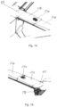
- FIGS 5 to 8 illustrating a rotor-wing multicopter according to the invention in a configuration with arms 200 folded against the body 100 and locked in a folded state, ready for storage or transportation.
- Figures 5 to 8 identify the lock slider 231 and the lock pin 232 of the arm folding hinge lock arrangement 230, the end portion 218 of the arm inner part 210 and the end portion 225 of the arm outer part 220 which both are of a shape that correspond to sections of a toroid, and the portion 215 of the arm inner part 210 and the portion 228 of the arm outer part 220 which are hollow toroidal sections and matchingly shaped to the end portions 225 and 218 so as to receive respective ones of the end portions 225 and 218, respectively, when the arm is rotated about the folding hinge from a folded to a deployed state.
- forces such as torque and shear acting around and across the longitudinal axis of the arm are coupled directly between inner and outer arm parts 210, 220 without stressing the hinge pin around which the arm outer part is rotated when
- Figure 8 also identifies a mounting track 145 in the unitary backbone 140 into which auxiliary equipment such as e.g. a camera foot may be mounted.
- auxiliary equipment such as e.g. a camera foot
- levers of the battery holding and locking means 190 are in position for locking and holding the batteries in place on the body, and that the L-shaped lever elements shown in figures 3 and 4 protruding from lower edges of sides of the forward 130 and rearward 150 end pieces are in figures 5 and 6 , as well as in figures 1 and 2 , positioned in recesses in the forward 130 and rearward 150 end pieces and substantially hidden between these and respective adjacent end sides 514 of the batteries when batteries 500 are fully installed on the body.
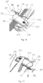
- Figure 9 shows elements and subassemblies of the body 100, such as bow end cap 110, optional forward adapter plate 120, forward end piece 130, body backbone 140 with electrical connector 180 for connecting to battery, rearward end piece 150 with parts of battery holding and locking arrangement 190, optional rearward adapter plate 160, and stern end cap 170, and elements and subassemblies of the rotor arm 200, such as arm inner part 210, arm folding hinge arrangement 230, and arm outer part 220, and elements and subassemblies of the rotors 400, such as motor mount 410, upper rotor assembly 420A, and lower rotor assembly 420B.
- the body 100 such as bow end cap 110, optional forward adapter plate 120, forward end piece 130, body backbone 140 with electrical connector 180 for connecting to battery, rearward end piece 150 with parts of battery holding and locking arrangement 190, optional rearward adapter plate 160, and stern end cap 170
- elements and subassemblies of the rotor arm 200 such as arm inner part 210
- Figure 10 illustrates and identifies the end portions 218 of the arm inner parts 210 and the end portions 225 of the arm outer parts 220 which are both of a shape that correspond to partial sections of a toroid, and the portions 215 of the arm inner parts 210 and the portions 228 of the arm outer parts 220 which are in part hollow toroidal like shaped sections, matchingly shaped as complements to the end portions 225 and 218, so as to be capable of receiving respective ones of the end portions 225 and 218, respectively, when the arm is rotated about the folding hinge from a folded to a deployed state.
- FIGS 11 and 12 illustrate and identify elements and sub-assemblies of battery locking means 190 parts to be disposed at a side of the forward 130 and rearward 150 end pieces of a multicopter embodiment of the aerial vehicle of the invention, and to figure 13 in which are illustrated and identified elements and sub-assemblies of battery holding and locking arrangement parts located at short sides 514 at ends of the elongate battery 500.
- Figures 11 and 12 illustrate and identify a rail 191, and a lever 192 with finger grab opening 196, lever rotation axis and bearing 195, carrier stud 193, and lever latching cam 194, and a lever latching pin and release button assembly 198.
- figure 13 illustrate and identifies features of battery 500 including a top long side 510, an inner long side 511, an outer long side 512, a bottom long side 513, and an end short side 514 of a battery 500, and on the end short side 514 comprising parts of the battery holding and locking means including a straight first recessed track 515 and an L-shaped second recessed track 516, both tracks having end openings at an edge of the bottom long side 513.
- the straight first recessed track 515 is dimensioned to receive at its opening the rail 191 to control the battery 500 to slide onto the body 100 and is positioned on the end short side 514 of the battery so as to position the battery next to a long side of the backbone 140 and position the electrical connector 580 of the battery in alignment with the electrical connector 180 of the body 100.
- the opening of the L-shaped second recessed track 516 is positioned on the end short side 514 of the battery so as to be capable of receiving the carrier stud 193 on the lever 192 positioned in the unlock and release position as illustrated in figure 11 .
- the corner of the L-shaped second recessed track 516 is positioned so as to meet the carrier stud 193 when the battery has sledded along the rail 191 till the point where the electrical connector 580 is about to make contact with the electrical connector 180, at which point the carrier stud 193 stops further movement of the battery until the lever is rotated about its rotation axis and bearing 195.
- the carrier stud 193 follows the circular path in an opposite direction, and limited by horizontal portion of the L-shaped second recessed track 516, the carrier stud 193 brings the battery 500 along and with leverage drives it to move further to a point at which the top 510 and bottom 513 long sides of the battery are elevated with respective top and bottom long sides of the backbone 140 and the electrical connector 580 of the battery is fully lifted out and disconnected to the electrical connector 180 of the body.
- the lever latching cam 194 contacts the spring biased lever latching pin of the lever latching pin and release button assembly 198, and displaces the lever latching pin until the lever is rotated to the point at which the lever latching pin drops into a recessed portion of the cam at a root of the cam, thereby latching the lever 192 secured in its position for holding and locking the battery 500 in place on the body 100.
- the displacement of the lever latching pin by the cam also displaces the release button of the lever latching pin and release button assembly 198 for the release button to be retracted into the respective end piece 130, 150.
- Sides of the release body that become hidden as the cam effects retraction of the release button are advantageously painted in a signal colour, thus providing when not retracted into the respective end piece a clearly visible signal of incorrectly positioned and non-latched lever.
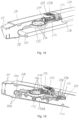
- FIGS 14 and 15 illustrate and identify in more detail forward 131 and rearward 151 shoulder portions of the forward 130 and rearward 150 end pieces that are adapted to receive and secure to the body 100 inner ends of arm inner parts 210, and constellation of arm inner parts 210, arm outer parts 220 and arm folding hinge arrangement 230 when arms 200 are fully unfolded and deployed ready for flight.
- FIGS 16 and 17 illustrate and identify in more detail forward 131 and rearward 151 shoulder portions of the forward 130 and rearward 150 end pieces that are adapted to receive and secure to the body 100 inner ends of arm inner parts 210, and constellation of arm inner parts 210, arm outer parts 220 and arm folding hinge arrangement 230 when arms 200 are fully folded in and ready for storage or transportation.
- locking means slider 231 operable to bring arm locking pin 232 in from its idle position at which it protrudes from an outer end of the arm inner part 210, and arm locking pin receiving opening 221 on the arm outer part 220 into which the arm locking pin 232 is protruding to secure the arm 200 in the fully unfolded and deployed ready for flight position.
- Figures 16 and 17 further illustrate release buttons fully retracted into respective end piece 130, 150, indicating levers 192 of the respective battery holding and locking means 190 are properly positioned to hold and lock battery 500.
- FIGS. 18 and 19 illustrate and identify in more detail arm folding hinge and locking arrangements with rotor arms in the fully unfolded and deployed and locked in this position when ready for flight.
- Axis of rotation for the folding of arms 200 is defined by a hinge ring 235 which is attached to inner arm part 210 by ring mount 235A positioned within arm outer part 220.
- a ring shaped cavity of the arm inner part 210 forms a race for the hinge ring 235, thereby providing a hinge allowing the arm inner 210 and outer 220 parts to remain connected and rotatable with respect to each other in all positions from fully folded in to fully unfolded and deployed positions.
- Arm locking pin 232 is connected to slider 231, and springs 233 provides bias to the arm lock slider 231 so as to keep it in an idling position at which the arm locking pin 232 is protruding into arm locking opening 221 arranged in the arm outer part 220.
- An interlock button 231A is provided in the arm lock slider 231 to blocking of any inadvertent movement the slider 231 until unblocked by a pushing of the interlock button 231A.
- a locking cam 234 is connected to slider 231 and positioned for lodging into one of a plurality of locking slot 236 provided on the hinge ring 235. Thereby, locking cam 234 and locking slot 236 proved a further means for keeping the arm parts locked in position in the fully unfolded and deployed position.
- At least one locking slot 236 is provided at an angular position of the hinge ring for allowing the locking cam to be lodged in the locking slot when the arm is fully folded, thereby proving locking of an arm outer part relative to a respective arm inner part also in the folded position to block the arms from unfolding inadvertently, e.g. during handling for transportation, maintenance, storage or other situations.
- Figures 18 and 19 also show inner portion 211 of the arm inner parts 210, constituted by a tapered off section shaped to fit with a matchingly shaped tapered off opening in an end piece part of the body, such as e.g. shoulder 131, shoulder 132 and shoulder 151.
- the end portion 211 of the arm inner parts 210 has a cross section outline corresponding to the shape of a trapezium, with a cross section at a tip of the end portion 211 that is smaller than cross section further in from the tip.
- a UAV implementing the invention may be an embodiment in which only upper motor and propeller assemblies 420A or only lower motor and propeller assemblies 420B are included.
- motor supports may be oriented differently from what has been disclosed herein, and the arm parts may be of different design, although only one design has been shown to illustrate and explain the invention.
Description
- The present invention relates to an unmanned aerial vehicle (UAV), as specified in the accompanying patent claims.
- Unmanned, remotely operated or autonomous, aerial vehicles have gained much popularity in recent years. Such vehicles, which are commonly referred to as drones, are now widely used for aerial photography and surveillance, transportation of cargo, etc., by professionals in law enforcement agencies and rescue organizations. There is thus a demand for drones that can carry comparably heavy loads, may be transported to a site in a compact state, and rapidly be deployed and ready for flight.
- The prior art includes
WO 2008/147484 A2 , which describes a modular vehicle having an air vehicle that can be coupled to cargo containers, land vehicles, sea vehicles, medical transport modules, etc. In one embodiment the air vehicle has a plurality of propellers positioned around a main airframe, which can provide vertical thrust and/or horizontal thrust. One or more of the propellers may be configured to tilt forward, backward, and/or side-to-side with respect to the airframe. - The prior art also includes
KR 10-1527544 B1 - The prior art also includes
WO 2017/185487 A1 , which describes a battery fixing and mounting structure for a battery self-dismounting unmanned aerial vehicle, comprising an unmanned aerial vehicle mainly body and a battery cover. A battery chamber used for accommodating a battery is formed in the bottom of the unmanned aerial vehicle mainly body. A hinged connection hole is formed in one side of the battery chamber. A hinged connection pillar matching the hinged connection hole is disposed on one corresponding side on the battery cover. The hinged connection pillar is hingedly connected in the hinged connection hole and enables the battery cover to be hingedly connected onto the unmanned aerial vehicle mainly body. - An object of the present invention is to provide a highly reliable and long-term stable rotor-wing multicopter type and rapidly deployable aerial vehicle with a plurality of motors, advantageously operable as a drone, and designed to carry heavy cargo loads, fixed to the fuselage or connected to the drone by slings. The loads may be in a range from about 5kg to about 500kg.
- The inventors have found that a rapidly deployable aerial vehicle having a rotating wing lift generating means, advantageously a rapidly deployable unmanned aerial vehicle (UAV), such as rapidly deployable unmanned multicopter, embodied with a unitary main fuselage and advantageously embodied with a swingable arm mount as illustrated and described herein, exhibits advantageous properties and capabilities that makes it highly desirable for use in applications where a manned aircraft, such as a manned airplane or a manned helicopter, involves high risk or high cost on personnel or equipment or meets other substantial limitations on its operation that prohibits its use, in particular in an emergency situation under adverse operating conditions. The apparatus of the present invention in particular capable of providing fast deployment and be ready for action in a matter of minutes with a stability that remains substantially unchanged over time.
- The invention is set forth and characterized in the main claim, while the dependent claims describe other characteristics of the invention.
- It is thus provided an unmanned aerial vehicle, having a main body comprising at least an elongate main frame, also referred to as a backbone, with a forward end piece and a rearward end piece, said end pieces being wider than the backbone and comprising coupling facilities for respective rotor arms, each said rotor arm configured for supporting motor and propeller assemblies; the unmanned aerial vehicle further comprises a pair of elongated batteries; the end pieces and at least a portion of the backbone form receptacles on both sides of the backbone for releasably receiving respective electric batteries, wherein the batteries, backbone and end pieces form an elongate and substantially rectangular body assembly.Each rotor arm comprises an arm inner part having on one end a coupling arrangement adapted for coupling to respective end pieces of the main body and on a second end a first part of an arm folding hinge, and an arm outer part having on one end an adapter for said motor and propeller assemblies and on a second end a second part of the arm folding hinge, and a displaceable and spring biased hinge lock arrangement disposed at the respective second ends of the arm inner and outer parts. The arm may further comprise a spring biased cotter pin adapted to enter a hole in the arm outer part when aligned in an unfolded position.
- The invention provides a swingable arm mount for an aerial vehicle having a lift generating means, the aerial vehicle being advantageously a multicopter.
- Accordingly, an example concerns an unmanned multicopter having a main body comprising
- an elongate "backbone" (central body/fuselage) made from a unitary piece of light metal extruded profile having a first end and a second end and therein four elongate cavities and at least one outer "backbone" long side and other profile features, such as for example a mounting track for attaching thereto equipment like a camera foot and the like,
- a forward end piece for mounting on the first end of the "backbone", and which has a width where it is to be mounted to the "backbone" that is wider than the backbone and provides at least a first and a second forward shoulder which each comprises a coupling facility for a rotor arm, optionally also a forward mounting facility for an undercarriage (at least one leg),
- a rearward end piece for mounting on the second end of the "backbone", and which has a width where it is to be mounted to the "backbone" that is wider than the backbone and provides at least a first and a second rearward shoulder which each comprises a coupling facility for a rotor arm, optionally also a rearward mounting facility for an undercarriage (at least one leg),
- a bow end cap, a stern end cap,
- an optional forward adapter plate providing a forward mounting facility for and an adapter between the forward end piece and the bow end cap,
- an optional rearward adapter plate providing a forward mounting facility for and an adapter between the rearward end piece and the stern end cap, and
- four foldable rotor arms, each comprising an inner arm part having on one end a coupling arrangement adapted for coupling to the coupling facility of an end piece and on a second end a first part of an arm folding hinge, and an outer arm part having on one end an adapter for a rotor assembly and on a second end a second part of the arm folding hinge, and a displaceable and spring biased hinge lock arrangement disposed in a first one of the inner and outer arm parts and comprising a spring biased cotter pin adapted to enter a hole in the other one of the inner and outer arm parts when aligned in an unfolded position, and four rotor assemblies each comprising at least a propeller on a motor on a rotor mount attached to a respective one of the adapters for a rotor assembly. Preferably, the invention can provide an unmanned multicopter having at least one elongate energy container, preferably an electric battery, having a first end, a second end and an outer battery long side adapted for being positioned adjacent to at least one long side of the "backbone", and which has on at least one of the first and second ends an attaching arrangement being adapted to be in fastening engagement with at least one co-operating attaching means arranged on at least one of the forward and rearward end pieces.
- The above and other characteristics of the invention will become clear from the following description of a preferential form of embodiment, given as a non-restrictive example, with reference to the attached schematic drawings, wherein:
-
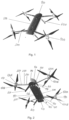
Figure 1 is a first perspective view drawing, illustrating seen from above an embodiment of a multicopter drone according to the invention complete and ready for flight; -
Figure 2 is a second perspective view drawing, illustrating seen from below the embodiment of a multicopter drone according to the invention illustrated infigure 1 ; -
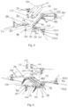
Figure 3 is a third perspective view drawing, illustrating seen from above the embodiment of a multicopter drone according to the invention illustrated infigures 1 and 2 , modified with batteries removed from and elevated above the body of the drone; -
Figure 4 is a fourth perspective view drawing, illustrating seen from below the embodiment of a multicopter drone according to the invention illustrated infigures 1, 2 and3 modified with batteries removed from and elevated above the body of the drone; -
Figure 5 is a first perspective view drawing, illustrating seen from above an embodiment of a multicopter drone according to the invention complete and folded for storage or transportation; -
Figure 6 is a second perspective view drawing, illustrating seen from below the embodiment of a multicopter drone according to the invention illustrated infigure 5 ; -
Figure 7 is a third perspective view drawing illustrating seen from above the embodiment of a multicopter drone according to the invention illustrated infigures 5 and 6 modified with batteries removed from the body of the drone; -
Figure 8 is a fourth perspective view drawing illustrating seen from below the embodiment of a multicopter drone according to the invention illustrated infigures 5, 6 and7 modified with batteries removed from the body of the drone; -
Figure 9 is a first exploded view drawing illustrating seen in perspective from above the main components of the embodiment of a multicopter drone according to the invention illustrated infigures 1, 2 ,3 and 4 ; -
Figure 10 is a second exploded view drawing illustrating seen in perspective from below the main components of the embodiment of a multicopter drone according to the invention illustrated infigures 1, 2 ,3, 4 and9 ; -
Figure 11 is a first perspective view detail drawing illustrating in a released state a battery holding and locking arrangement of the multicopter drone according to the invention; -
Figure 12 is a second perspective view detail drawing illustrating in a locked state the battery holding and locking arrangement of the multicopter drone according to the invention also illustrated infigure 11 ; -
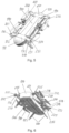
Figure 13 is a first perspective view detail drawing of elements of the battery locking arrangement on an end portion of a battery for a multicopter drone according to the invention; -
Figure 14 is a first perspective view detail drawing illustrating in a deployed state a forward arm folding hinge portion of a rotor arm for a multicopter drone according to the invention; -
Figure 15 is a first perspective view detail drawing illustrating in a deployed state a rearward arm folding in hinge portion of a rotor arm for a multicopter drone according to the invention; -
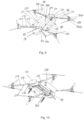
Figure 16 is a first perspective view detail drawing illustrating in a folded state a forward arm folding hinge portion of a rotor arm for a multicopter drone according to the invention; -
Figure 17 is a first perspective view detail drawing illustrating in a folded state a rearward arm folding in hinge portion of a rotor arm for a multicopter drone according to the invention; -
Figure 18 is a first cross section view detail drawing illustrating seen in a first perspective from above in a deployed state a forward arm folding hinge portion of a rotor arm for a multicopter drone according to the invention; -
Figure 19 is a second cross section view detail drawing illustrating seen in a second perspective from above in a deployed state the rearward arm folding in hinge portion of a rotor arm for a multicopter drone according to the invention also illustrated infigure 17 . - The following description may use terms such as "horizontal", "vertical", "lateral", "back and forth", "up and down", "upper", "lower", "inner", "outer", "forward", "rearward", etc. These terms generally refer to the views and orientations as shown in the drawings and that are associated with a normal use of the invention. The terms are used for the reader's convenience only and shall not be limiting.
- For simplicity in the following description, the assembly comprising a complete rotor arm and a rotor assembly comprising motor mount, motors and propellers is frequently referred to as the "arm". The drone body comprising a main frame (commonly referred to as a "backbone"), end pieces, end caps and components mounted thereon, but without the batteries, arms and undercarriage, is frequently referred to as the "body".
- Reference is first made to the drawing of
figures 1 to 4 , illustrating a complete rotor-wing multicopter according to an embodiment of the invention in a configuration witharms 200 deployed and extending out from thebody 100 and locked in a fully deployed state, ready for flight.Figure 1 shows main assemblies and components such as thebody 100 with a pair ofbatteries 500 mounted thereon, so as to form an elongate and substantially rectangular body assembly. A plurality ofrotor arms 200 withrotor assemblies 400, and an undercarriage including a plurality oflegs 600, are mounted on thebody 100. -
Figure 2 shows components and sub-assemblies of thebody 100, such as a forward endcap 110 with sensor windows 111, an optionalforward adapter plate 120, aforward end piece 130, abackbone 140, a rearward end piece 150, an optional rearward adapter plate 160, astern endcap 170,battery locking arrangements 190, components and subassemblies of thearms 200, such as arminner part 210, armouter part 220, and arm foldinghinge locking arrangement 230, and components and subassemblies of therotor assemblies 400, such as rotor mounts 410, upper motor andpropeller assemblies 420A, and lower motor and propeller assemblies 420B. -
Figures 3 and 4 show thebody backbone 140 andforward shoulders 131 and 132, comprising adapters arranged on theforward end piece 130 arranged to provide for secure attachment offorward arms 200 to thebody 100. Correspondingly, the rearward end piece 150 includesrearward shoulders 151 and 152 comprising adapters arranged on the rearward end piece 150 arranged to provide for secure attachment ofrearward arms 200 to thebody 100. - A
battery connector 180 for electric connection is provided on at least one side of thebackbone 140, adapted to provide electrical connection with a matingelectrical connector 580 on the battery. Battery holding and locking meansfirst parts 190 are disposed on respective ones of sides of the forward 130 and rearward 150 end pieces that are substantially perpendicular to a longitudinal axis of thebody 100 and facing each other. Battery holding and locking meanssecond parts 514, designed to cooperate and engage with the battery holding and locking meansfirst parts 190, are disposed on respective ends of eachbattery 500. Referring tofigures 3 and 4 , it should be noted that levers of the battery holding and locking means 190 are shown in a position for unlocking and releasing the batteries, and are seen as L-shaped elements protruding from lower edges of sides of the forward 130 and rearward 150 end pieces that are facing each other and are visible whenbatteries 500 are not installed between these sides on the body. - Reference is made to
figures 5 to 8 , illustrating a rotor-wing multicopter according to the invention in a configuration witharms 200 folded against thebody 100 and locked in a folded state, ready for storage or transportation.Figures 5 to 8 identify thelock slider 231 and thelock pin 232 of the arm foldinghinge lock arrangement 230, theend portion 218 of the arminner part 210 and theend portion 225 of the armouter part 220 which both are of a shape that correspond to sections of a toroid, and theportion 215 of the arminner part 210 and theportion 228 of the armouter part 220 which are hollow toroidal sections and matchingly shaped to theend portions end portions outer arm parts -
Figure 8 also identifies a mounting track 145 in theunitary backbone 140 into which auxiliary equipment such as e.g. a camera foot may be mounted. It should be noted that infigures 5 to 8 , as well as infigures 1 and 2 , levers of the battery holding and locking means 190 are in position for locking and holding the batteries in place on the body, and that the L-shaped lever elements shown infigures 3 and 4 protruding from lower edges of sides of the forward 130 and rearward 150 end pieces are infigures 5 and 6 , as well as infigures 1 and 2 , positioned in recesses in the forward 130 and rearward 150 end pieces and substantially hidden between these and respectiveadjacent end sides 514 of the batteries whenbatteries 500 are fully installed on the body. - Reference is now made to
figures 9 and 10 , in which main elements and sub-assemblies of a multicopter embodiment of the aerial vehicle of the invention are illustrated and identified.Figure 9 shows elements and subassemblies of thebody 100, such as bow end cap 110, optionalforward adapter plate 120,forward end piece 130,body backbone 140 withelectrical connector 180 for connecting to battery, rearward end piece 150 with parts of battery holding and lockingarrangement 190, optional rearward adapter plate 160, andstern end cap 170, and elements and subassemblies of therotor arm 200, such as arminner part 210, armfolding hinge arrangement 230, and armouter part 220, and elements and subassemblies of therotors 400, such asmotor mount 410,upper rotor assembly 420A, and lower rotor assembly 420B.Figure 10 illustrates and identifies theend portions 218 of the arminner parts 210 and theend portions 225 of the armouter parts 220 which are both of a shape that correspond to partial sections of a toroid, and theportions 215 of the arminner parts 210 and theportions 228 of the armouter parts 220 which are in part hollow toroidal like shaped sections, matchingly shaped as complements to theend portions end portions - Reference is now made to
figures 11 and 12 , which illustrate and identify elements and sub-assemblies of battery locking means 190 parts to be disposed at a side of the forward 130 and rearward 150 end pieces of a multicopter embodiment of the aerial vehicle of the invention, and tofigure 13 in which are illustrated and identified elements and sub-assemblies of battery holding and locking arrangement parts located atshort sides 514 at ends of theelongate battery 500. -
Figures 11 and 12 illustrate and identify a rail 191, and a lever 192 with finger grab opening 196, lever rotation axis and bearing 195, carrier stud 193, and lever latching cam 194, and a lever latching pin andrelease button assembly 198. For convenience, next reference is made tofigure 13 , which illustrate and identifies features ofbattery 500 including a top long side 510, an inner long side 511, an outer long side 512, a bottom long side 513, and an endshort side 514 of abattery 500, and on the endshort side 514 comprising parts of the battery holding and locking means including a straight first recessed track 515 and an L-shaped second recessed track 516, both tracks having end openings at an edge of the bottom long side 513. The straight first recessed track 515 is dimensioned to receive at its opening the rail 191 to control thebattery 500 to slide onto thebody 100 and is positioned on the endshort side 514 of the battery so as to position the battery next to a long side of thebackbone 140 and position theelectrical connector 580 of the battery in alignment with theelectrical connector 180 of thebody 100. - The opening of the L-shaped second recessed track 516 is positioned on the end
short side 514 of the battery so as to be capable of receiving the carrier stud 193 on the lever 192 positioned in the unlock and release position as illustrated infigure 11 . The corner of the L-shaped second recessed track 516 is positioned so as to meet the carrier stud 193 when the battery has sledded along the rail 191 till the point where theelectrical connector 580 is about to make contact with theelectrical connector 180, at which point the carrier stud 193 stops further movement of the battery until the lever is rotated about its rotation axis and bearing 195. Then, rotation of the lever towards its battery locking position makes the carrier stud 193 follow a circular path, and limited by horizontal portion of the L-shaped second recessed track 516, the carrier stud 193 brings thebattery 500 along and with leverage drives it to move further to a point at which the top 510 and bottom 513 long sides of the battery are substantially flush with respective top and bottom long sides of thebackbone 140 and theelectrical connector 580 of the battery is fully mated with and connected to theelectrical connector 180 of the body. - Conversely, for a
battery 500 already installed on thebody 100 in a held and locked position, by rotation of the lever towards the unlock and release position, the carrier stud 193 follows the circular path in an opposite direction, and limited by horizontal portion of the L-shaped second recessed track 516, the carrier stud 193 brings thebattery 500 along and with leverage drives it to move further to a point at which the top 510 and bottom 513 long sides of the battery are elevated with respective top and bottom long sides of thebackbone 140 and theelectrical connector 580 of the battery is fully lifted out and disconnected to theelectrical connector 180 of the body. On entering the position for holding and locking thebattery 500, the lever latching cam 194 contacts the spring biased lever latching pin of the lever latching pin andrelease button assembly 198, and displaces the lever latching pin until the lever is rotated to the point at which the lever latching pin drops into a recessed portion of the cam at a root of the cam, thereby latching the lever 192 secured in its position for holding and locking thebattery 500 in place on thebody 100. The displacement of the lever latching pin by the cam also displaces the release button of the lever latching pin andrelease button assembly 198 for the release button to be retracted into therespective end piece 130, 150. Sides of the release body that become hidden as the cam effects retraction of the release button are advantageously painted in a signal colour, thus providing when not retracted into the respective end piece a clearly visible signal of incorrectly positioned and non-latched lever. - Reference is now made to
figures 14 and 15 , which illustrate and identify in more detail forward 131 and rearward 151 shoulder portions of the forward 130 and rearward 150 end pieces that are adapted to receive and secure to thebody 100 inner ends of arminner parts 210, and constellation of arminner parts 210, armouter parts 220 and armfolding hinge arrangement 230 whenarms 200 are fully unfolded and deployed ready for flight. - Reference is now made to
figures 16 and 17 , which illustrate and identify in more detail forward 131 and rearward 151 shoulder portions of the forward 130 and rearward 150 end pieces that are adapted to receive and secure to thebody 100 inner ends of arminner parts 210, and constellation of arminner parts 210, armouter parts 220 and armfolding hinge arrangement 230 whenarms 200 are fully folded in and ready for storage or transportation. In this constellation is also shown locking meansslider 231 operable to bringarm locking pin 232 in from its idle position at which it protrudes from an outer end of the arminner part 210, and arm locking pin receiving opening 221 on the armouter part 220 into which thearm locking pin 232 is protruding to secure thearm 200 in the fully unfolded and deployed ready for flight position.Figures 16 and 17 , further illustrate release buttons fully retracted intorespective end piece 130, 150, indicating levers 192 of the respective battery holding and locking means 190 are properly positioned to hold and lockbattery 500. - Reference is now made to
figures 18 and 19 , which illustrate and identify in more detail arm folding hinge and locking arrangements with rotor arms in the fully unfolded and deployed and locked in this position when ready for flight. Axis of rotation for the folding ofarms 200 is defined by ahinge ring 235 which is attached toinner arm part 210 byring mount 235A positioned within armouter part 220. A ring shaped cavity of the arminner part 210 forms a race for thehinge ring 235, thereby providing a hinge allowing the arm inner 210 and outer 220 parts to remain connected and rotatable with respect to each other in all positions from fully folded in to fully unfolded and deployed positions.Arm locking pin 232 is connected toslider 231, and springs 233 provides bias to thearm lock slider 231 so as to keep it in an idling position at which thearm locking pin 232 is protruding into arm locking opening 221 arranged in the armouter part 220. - An
interlock button 231A is provided in thearm lock slider 231 to blocking of any inadvertent movement theslider 231 until unblocked by a pushing of theinterlock button 231A. A lockingcam 234 is connected toslider 231 and positioned for lodging into one of a plurality of lockingslot 236 provided on thehinge ring 235. Thereby, lockingcam 234 and lockingslot 236 proved a further means for keeping the arm parts locked in position in the fully unfolded and deployed position. At least onelocking slot 236 is provided at an angular position of the hinge ring for allowing the locking cam to be lodged in the locking slot when the arm is fully folded, thereby proving locking of an arm outer part relative to a respective arm inner part also in the folded position to block the arms from unfolding inadvertently, e.g. during handling for transportation, maintenance, storage or other situations.Figures 18 and 19 also showinner portion 211 of the arminner parts 210, constituted by a tapered off section shaped to fit with a matchingly shaped tapered off opening in an end piece part of the body, such as e.g.shoulder 131, shoulder 132 and shoulder 151. Advantageously, theend portion 211 of the arminner parts 210 has a cross section outline corresponding to the shape of a trapezium, with a cross section at a tip of theend portion 211 that is smaller than cross section further in from the tip. - As an example, a UAV implementing the invention may be an embodiment in which only upper motor and
propeller assemblies 420A or only lower motor and propeller assemblies 420B are included. Similarly, motor supports may be oriented differently from what has been disclosed herein, and the arm parts may be of different design, although only one design has been shown to illustrate and explain the invention.
Claims (10)
- An unmanned aerial vehicle, having a main body (100), rotor arms (200), and motor and propeller assemblies (400, 420A,B),wherein the rotor arms are configured for supporting the motor and propeller assemblies; and wherein the main body (100) comprises at least an elongate main frame, also referred to as a backbone, (140) with a forward end piece (130) and a rearward end piece (150), wherein- said end pieces (130, 150) are wider than the backbone (140) and comprising coupling facilities for respective rotor arms (200);- the unmanned aerial vehicle further comprises a pair of elongated batteries (500);- the end pieces (130, 150) and at least a portion of the backbone (140) form receptacles on both sides of the backbone for releasably receiving respective electric batteries (500), wherein the batteries, backbone and end pieces form an elongate and substantially rectangular body assembly, said unmanned aerial vehicle being characterised in that- each rotor arm (200) comprises an arm inner part (210) having on one end a coupling arrangement adapted for coupling to respective end pieces of the main body and on a second end a first part of an arm folding hinge, and an arm outer part (220) having on one end an adapter for said motor and propeller assemblies and on a second end a second part of the arm folding hinge, and a displaceable and spring biased hinge lock arrangement (230) disposed at the respective second ends of the arm inner part and of the arm outer part.
- The unmanned aerial vehicle of claim 1, further comprising a spring biased cotter pin (232) adapted to enter a hole in the arm outer part (220) when aligned in an unfolded position.
- The unmanned aerial vehicle of any one of claims 1-2, further comprising an attaching arrangement being adapted to be in fastening engagement with at least one co-operating attaching means arranged on at least one of the forward and rearward end pieces.
- The unmanned aerial vehicle of any one of claims 1-3, further comprising battery locking means (190) parts arranged at a side of the forward (130) and rearward (150) end pieces for releasable locking engagement with corresponding battery holding and locking arrangement parts located at short sides (514) at ends of the battery (500).
- The unmanned aerial vehicle of claim 4, wherein the battery (500) comprises a top long side (510), an inner long side (511), an outer long side (512), a bottom long side (513), and an end short side (514), and wherein the end short side (514) comprises parts of the battery holding and locking means including a straight first recessed track (515) and an L-shaped second recessed track (516), both tracks having end openings at an edge of the bottom long side (513).
- The unmanned aerial vehicle of claim 5, wherein the straight first recessed track (515) is dimensioned to receive at its opening a rail (191) to control the battery (500) to slide onto the body (100) and is positioned on the end short side (514) of the battery so as to position the battery next to a long side of the backbone (140) and position an electrical connector (580) of the battery in alignment with an electrical connector (180) of the body 100.
- The unmanned aerial vehicle of claim 6, wherein an opening of the L-shaped second recessed track (516) is positioned on the end short side (514) of the battery so as to be capable of receiving a carrier stud (193) on a lever (192) positioned in the unlock and release position, wherein the corner of the L-shaped second recessed track (516) is positioned so as to meet the carrier stud (193) in a position, wherein the battery is sledded along the rail (191) to a point where an electrical connector (580) is about to make contact with the electrical connector (180), wherein the carrier stud (193) is configured to stop further movement of the battery unless the lever (192) is rotated about its rotation axis and bearing (195).
- The unmanned aerial vehicle of claim 7, wherein a rotation of the lever towards its battery locking position makes the carrier stud (193) follow a circular path, and limited by horizontal portion of the L-shaped second recessed track (516), the carrier stud (193) is configured to bring the battery (500) along and with leverage drive it to move further to a point at which the top (510) and bottom (513) long sides of the battery are substantially flush with respective top and bottom long sides of the backbone (140) and the electrical connector (580) of the battery is fully mated with and connected to the electrical connector 180 of the body.
- The unmanned aerial vehicle of claim 8, wherein when a battery (500) already is installed on the body (100) in a held and locked position, by rotation of the lever towards the unlock and release position, the carrier stud (193) is configured to follow the circular path in an opposite direction, and limited by horizontal portion of the L-shaped second recessed track (516), the carrier stud (193) is configured to bring the battery (500) along and with leverage drive it to move further to a point at which the top (510) and bottom (513) long sides of the battery are elevated with respective top and bottom long sides of the backbone (140) and the electrical connector (580) of the battery is fully lifted out and disconnected from the electrical connector (180) of the body.
- The unmanned aerial vehicle of any one of claims 1-9, wherein the backbone has therein four elongate cavities and at least one outer backbone long side for attaching thereto equipment such as a camera foot.
Applications Claiming Priority (2)
| Application Number | Priority Date | Filing Date | Title |
|---|---|---|---|
| NO20180080A NO344274B1 (en) | 2018-01-17 | 2018-01-17 | An unmanned aerial vehicle having rotating wing lift generating means, advantageously a multicopter with a unitary main fuselage and foldable rotor arms. |
| PCT/NO2019/050008 WO2019143255A1 (en) | 2018-01-17 | 2019-01-17 | An unmanned aerial vehicle |
Publications (2)
| Publication Number | Publication Date |
|---|---|
| EP3740428A1 EP3740428A1 (en) | 2020-11-25 |
| EP3740428B1 true EP3740428B1 (en) | 2023-11-29 |
Family
ID=65409446
Family Applications (1)
| Application Number | Title | Priority Date | Filing Date |
|---|---|---|---|
| EP19704894.5A Active EP3740428B1 (en) | 2018-01-17 | 2019-01-17 | An unmanned aerial vehicle |
Country Status (9)
| Country | Link |
|---|---|
| US (1) | US20210078704A1 (en) |
| EP (1) | EP3740428B1 (en) |
| JP (1) | JP7285847B2 (en) |
| KR (1) | KR102652241B1 (en) |
| CN (1) | CN111615488A (en) |
| AU (1) | AU2019209760A1 (en) |
| CA (1) | CA3088981A1 (en) |
| NO (1) | NO344274B1 (en) |
| WO (1) | WO2019143255A1 (en) |
Families Citing this family (13)
| Publication number | Priority date | Publication date | Assignee | Title |
|---|---|---|---|---|
| MA53618A (en) * | 2018-09-11 | 2021-12-15 | Douglas Morgan Hanna | UNMANNED AERIAL TRANSPORT VEHICLE WITH DISTRIBUTED BATTERIES AND METHOD FOR POWERING IT |
| WO2021072242A1 (en) * | 2019-10-11 | 2021-04-15 | Reign Maker Visual Communications Llc | Water sampling device |
| US20210214067A1 (en) * | 2020-01-13 | 2021-07-15 | Skydio, Inc. | Autonomous Unmanned Aerial Vehicle With Folding Collapsible Arms |
| DE102020104783A1 (en) * | 2020-02-24 | 2021-08-26 | Volocopter Gmbh | Battery holding device, battery system, aircraft and method for changing a battery for an aircraft |
| WO2021230957A1 (en) * | 2020-05-14 | 2021-11-18 | Massachusetts Institute Of Technology | Aerial vehicle with tape spring arms |
| KR102347832B1 (en) * | 2020-07-02 | 2022-01-05 | 한국항공우주연구원 | Multi-copter |
| CN112224396A (en) * | 2020-10-20 | 2021-01-15 | 北京理工大学 | Six-rotor unmanned aerial vehicle with double-layer staggered arms and capable of being folded transversely |
| US11845544B2 (en) * | 2020-12-28 | 2023-12-19 | Textron Innovations, Inc. | Foldable aircraft |
| KR102314218B1 (en) * | 2021-04-06 | 2021-10-18 | 주식회사 보라스카이 | Foldable drone for reconnaissance |
| US20230039018A1 (en) * | 2021-08-09 | 2023-02-09 | InSitu, Inc., a subsidiary of the Boeing Company | Unmanned aerial vehicles including wing capture devices and related methods |
| CN113415407B (en) * | 2021-08-10 | 2022-11-29 | 珠海紫燕无人飞行器有限公司 | Collapsible unmanned aerial vehicle |
| WO2023019404A1 (en) * | 2021-08-16 | 2023-02-23 | 深圳市大疆创新科技有限公司 | Arm assembly of aerial vehicle and aerial vehicle |
| CN114489145B (en) * | 2022-04-13 | 2022-07-12 | 山东亿华天产业发展集团有限公司 | Unmanned aerial vehicle photogrammetry path planning method and low-altitude flight unmanned aerial vehicle system |
Family Cites Families (25)
| Publication number | Priority date | Publication date | Assignee | Title |
|---|---|---|---|---|
| US8453962B2 (en) * | 2007-02-16 | 2013-06-04 | Donald Orval Shaw | Modular flying vehicle |
| US8288035B2 (en) * | 2009-01-09 | 2012-10-16 | Electrochem Solutions, Inc. | Modular battery pack |
| US20140061376A1 (en) * | 2010-05-26 | 2014-03-06 | Aerovironment Inc | Reconfigurable battery-operated vehicle system |
| US8774982B2 (en) * | 2010-08-26 | 2014-07-08 | Leptron Industrial Robotic Helicopters, Inc. | Helicopter with multi-rotors and wireless capability |
| KR101527544B1 (en) * | 2015-01-10 | 2015-06-10 | 최종필 | The multi-rotor type folding drone |
| US9409645B1 (en) * | 2015-03-02 | 2016-08-09 | Google, Inc. | Unmanned aerial vehicle for collaboration |
| US9738380B2 (en) * | 2015-03-16 | 2017-08-22 | XCraft Enterprises, LLC | Unmanned aerial vehicle with detachable computing device |
| KR101773674B1 (en) * | 2015-09-10 | 2017-08-31 | 이미란 | Structure for inserting and removal battery and drone including the same |
| US10807731B2 (en) * | 2015-09-25 | 2020-10-20 | Amazon Technologies, Inc. | Floating motor mount for unmanned aerial vehicles |
| WO2017131451A1 (en) | 2016-01-26 | 2017-08-03 | 주식회사 아모그린텍 | Drone |
| EP3971084A1 (en) * | 2016-02-22 | 2022-03-23 | SZ DJI Technology Co., Ltd. | Aéronef multi-rotor pliable |
| FR3048187A1 (en) * | 2016-02-25 | 2017-09-01 | Parrot Drones | DRONE WITH BATTERY PACK |
| US10870477B1 (en) * | 2016-04-05 | 2020-12-22 | Fpv Manuals Llc | Foldable arm mechanism for rotary wing aircraft |
| US10780970B2 (en) * | 2016-04-06 | 2020-09-22 | Harris Aerial Llc | Folding heavy-lift unmanned vehicle frame |
| KR102151787B1 (en) * | 2016-04-27 | 2020-09-03 | 한화디펜스 주식회사 | A flying moving apparatus |
| CN106564582B (en) * | 2016-04-27 | 2022-06-24 | 北京远度互联科技有限公司 | Unmanned plane |
| CN205633009U (en) * | 2016-04-28 | 2016-10-12 | 深圳市龙云创新航空科技有限公司 | But self -discharging battery formula unmanned aerial vehicle battery fixed mounting structure |
| KR101919574B1 (en) * | 2016-05-27 | 2018-11-19 | 주식회사 유비파이 | A unmanned aerial vehicle |
| KR20170136309A (en) * | 2016-06-01 | 2017-12-11 | 정명률 | Drone |
| US10710701B2 (en) * | 2016-12-19 | 2020-07-14 | Haoxiang Electric Energy (Kunshan) Co., Ltd. | Foldable multi-rotor UAV |
| CN206476093U (en) * | 2016-12-27 | 2017-09-08 | 歌尔科技有限公司 | A kind of unmanned plane |
| CN106995052B (en) * | 2017-03-23 | 2020-01-24 | 沈阳无距科技有限公司 | Multi-shaft unmanned aerial vehicle |
| KR102323447B1 (en) * | 2017-06-08 | 2021-11-08 | 삼성전자주식회사 | Transformable unmanned aerial vehicle |
| IL252808B2 (en) * | 2017-06-11 | 2023-06-01 | Spear U A V Ltd | Launched unmanned aerial vehicle |
| FR3070607B1 (en) * | 2017-09-07 | 2020-09-04 | Parrot Drones | ROTATING BLADE DRONE INCLUDING A FOLDABLE DRONE STRUCTURE |
-
2018
- 2018-01-17 NO NO20180080A patent/NO344274B1/en unknown
-
2019
- 2019-01-17 US US16/962,491 patent/US20210078704A1/en active Pending
- 2019-01-17 AU AU2019209760A patent/AU2019209760A1/en active Pending
- 2019-01-17 KR KR1020207023562A patent/KR102652241B1/en active IP Right Grant
- 2019-01-17 CN CN201980008757.6A patent/CN111615488A/en active Pending
- 2019-01-17 CA CA3088981A patent/CA3088981A1/en active Pending
- 2019-01-17 EP EP19704894.5A patent/EP3740428B1/en active Active
- 2019-01-17 JP JP2020539262A patent/JP7285847B2/en active Active
- 2019-01-17 WO PCT/NO2019/050008 patent/WO2019143255A1/en unknown
Also Published As
| Publication number | Publication date |
|---|---|
| US20210078704A1 (en) | 2021-03-18 |
| KR102652241B1 (en) | 2024-03-28 |
| NO344274B1 (en) | 2019-10-21 |
| WO2019143255A1 (en) | 2019-07-25 |
| CA3088981A1 (en) | 2019-07-25 |
| EP3740428A1 (en) | 2020-11-25 |
| NO20180080A1 (en) | 2019-07-18 |
| KR20200106197A (en) | 2020-09-11 |
| AU2019209760A1 (en) | 2020-09-03 |
| JP7285847B2 (en) | 2023-06-02 |
| JP2021512002A (en) | 2021-05-13 |
| CN111615488A (en) | 2020-09-01 |
Similar Documents
| Publication | Publication Date | Title |
|---|---|---|
| EP3740428B1 (en) | An unmanned aerial vehicle | |
| US11167848B2 (en) | Unmanned aerial vehicle with enhanced cargo storage | |
| US20210371081A1 (en) | Air-Launched Unmanned Aerial Vehicle | |
| US10399703B2 (en) | Articulated support for unmanned aircraft system | |
| CN110506003B (en) | Modular aircraft with vertical takeoff and landing capability and method of operating the same | |
| US5779190A (en) | Portable unmanned aerial vehicle | |
| AU2005290315B2 (en) | Air-launchable aircraft and method of use | |
| KR101456035B1 (en) | The rotor arm device of multi-rotor type drone | |
| US10549850B1 (en) | Portable multithruster unmanned aircraft | |
| CN107117285A (en) | Unmanned plane provided with foldable unmanned plane supporting member | |
| US11014647B2 (en) | Locking mechanism, propeller, motor, propulsion system assembly, and aircraft | |
| CN107021205B (en) | Assembly and method for reconfiguring a door of an aircraft fuselage | |
| US20220135217A1 (en) | Autonomous Payload Deployment Aircraft | |
| WO2015115913A1 (en) | Multipurpose aircraft | |
| JP2011042258A (en) | Ground operation method and ground operation facility for unmanned airship | |
| CN209852565U (en) | Aircraft tail, wing panel and aircraft | |
| US11702187B2 (en) | Collapsible pylons for drone aircraft | |
| CN210852886U (en) | Folding piece of folding usefulness of unmanned aerial vehicle | |
| CN214216122U (en) | Folded form unmanned aerial vehicle | |
| CN117342008A (en) | But quick assembly disassembly's high navigational speed mixes wing unmanned aerial vehicle | |
| CN114572417A (en) | Quick locking device and aircraft comprising same | |
| CN117864469A (en) | Aerial docking mechanism of unmanned aerial vehicle | |
| CN109927879A (en) | Unmanned plane equipped with foldable unmanned plane supporting member |
Legal Events
| Date | Code | Title | Description |
|---|---|---|---|
| STAA | Information on the status of an ep patent application or granted ep patent |
Free format text: STATUS: UNKNOWN |
|
| STAA | Information on the status of an ep patent application or granted ep patent |
Free format text: STATUS: THE INTERNATIONAL PUBLICATION HAS BEEN MADE |
|
| PUAI | Public reference made under article 153(3) epc to a published international application that has entered the european phase |
Free format text: ORIGINAL CODE: 0009012 |
|
| STAA | Information on the status of an ep patent application or granted ep patent |
Free format text: STATUS: REQUEST FOR EXAMINATION WAS MADE |
|
| 17P | Request for examination filed |
Effective date: 20200814 |
|
| AK | Designated contracting states |
Kind code of ref document: A1 Designated state(s): AL AT BE BG CH CY CZ DE DK EE ES FI FR GB GR HR HU IE IS IT LI LT LU LV MC MK MT NL NO PL PT RO RS SE SI SK SM TR |
|
| AX | Request for extension of the european patent |
Extension state: BA ME |
|
| DAV | Request for validation of the european patent (deleted) | ||
| DAX | Request for extension of the european patent (deleted) | ||
| STAA | Information on the status of an ep patent application or granted ep patent |
Free format text: STATUS: EXAMINATION IS IN PROGRESS |
|
| 17Q | First examination report despatched |
Effective date: 20220518 |
|
| REG | Reference to a national code |
Ref country code: DE Ref legal event code: R079 Ref document number: 602019042305 Country of ref document: DE Free format text: PREVIOUS MAIN CLASS: B64C0039020000 Ipc: B64U0030293000 Ref country code: DE Free format text: PREVIOUS MAIN CLASS: B64C0039020000 Ipc: B64U0030293000 |
|
| GRAP | Despatch of communication of intention to grant a patent |
Free format text: ORIGINAL CODE: EPIDOSNIGR1 |
|
| STAA | Information on the status of an ep patent application or granted ep patent |
Free format text: STATUS: GRANT OF PATENT IS INTENDED |
|
| RIC1 | Information provided on ipc code assigned before grant |
Ipc: B64U 20/50 20230101ALI20230612BHEP Ipc: B64U 30/293 20230101AFI20230612BHEP |
|
| INTG | Intention to grant announced |
Effective date: 20230705 |
|
| GRAS | Grant fee paid |
Free format text: ORIGINAL CODE: EPIDOSNIGR3 |
|
| GRAA | (expected) grant |
Free format text: ORIGINAL CODE: 0009210 |
|
| STAA | Information on the status of an ep patent application or granted ep patent |
Free format text: STATUS: THE PATENT HAS BEEN GRANTED |
|
| AK | Designated contracting states |
Kind code of ref document: B1 Designated state(s): AL AT BE BG CH CY CZ DE DK EE ES FI FR GB GR HR HU IE IS IT LI LT LU LV MC MK MT NL NO PL PT RO RS SE SI SK SM TR |
|
| REG | Reference to a national code |
Ref country code: GB Ref legal event code: FG4D |
|
| REG | Reference to a national code |
Ref country code: CH Ref legal event code: EP |
|
| REG | Reference to a national code |
Ref country code: DE Ref legal event code: R096 Ref document number: 602019042305 Country of ref document: DE |
|
| REG | Reference to a national code |
Ref country code: IE Ref legal event code: FG4D |
|
| REG | Reference to a national code |
Ref country code: SE Ref legal event code: TRGR |
|
| REG | Reference to a national code |
Ref country code: LT Ref legal event code: MG9D |
|
| REG | Reference to a national code |
Ref country code: NL Ref legal event code: MP Effective date: 20231129 |
|
| PG25 | Lapsed in a contracting state [announced via postgrant information from national office to epo] |
Ref country code: GR Free format text: LAPSE BECAUSE OF FAILURE TO SUBMIT A TRANSLATION OF THE DESCRIPTION OR TO PAY THE FEE WITHIN THE PRESCRIBED TIME-LIMIT Effective date: 20240301 |
|
| PG25 | Lapsed in a contracting state [announced via postgrant information from national office to epo] |
Ref country code: IS Free format text: LAPSE BECAUSE OF FAILURE TO SUBMIT A TRANSLATION OF THE DESCRIPTION OR TO PAY THE FEE WITHIN THE PRESCRIBED TIME-LIMIT Effective date: 20240329 |
|
| PG25 | Lapsed in a contracting state [announced via postgrant information from national office to epo] |
Ref country code: LT Free format text: LAPSE BECAUSE OF FAILURE TO SUBMIT A TRANSLATION OF THE DESCRIPTION OR TO PAY THE FEE WITHIN THE PRESCRIBED TIME-LIMIT Effective date: 20231129 |
|
| PGFP | Annual fee paid to national office [announced via postgrant information from national office to epo] |
Ref country code: ES Payment date: 20240216 Year of fee payment: 6 |