KR20170136309A - Drone - Google Patents
Drone Download PDFInfo
- Publication number
- KR20170136309A KR20170136309A KR1020160068233A KR20160068233A KR20170136309A KR 20170136309 A KR20170136309 A KR 20170136309A KR 1020160068233 A KR1020160068233 A KR 1020160068233A KR 20160068233 A KR20160068233 A KR 20160068233A KR 20170136309 A KR20170136309 A KR 20170136309A
- Authority
- KR
- South Korea
- Prior art keywords
- flight
- disposed
- motor
- arm
- drone
- Prior art date
Links
Images


Classifications
-
- B—PERFORMING OPERATIONS; TRANSPORTING
- B64—AIRCRAFT; AVIATION; COSMONAUTICS
- B64C—AEROPLANES; HELICOPTERS
- B64C39/00—Aircraft not otherwise provided for
- B64C39/02—Aircraft not otherwise provided for characterised by special use
- B64C39/024—Aircraft not otherwise provided for characterised by special use of the remote controlled vehicle type, i.e. RPV
-
- B—PERFORMING OPERATIONS; TRANSPORTING
- B64—AIRCRAFT; AVIATION; COSMONAUTICS
- B64C—AEROPLANES; HELICOPTERS
- B64C27/00—Rotorcraft; Rotors peculiar thereto
- B64C27/04—Helicopters
- B64C27/08—Helicopters with two or more rotors
-
- B—PERFORMING OPERATIONS; TRANSPORTING
- B64—AIRCRAFT; AVIATION; COSMONAUTICS
- B64C—AEROPLANES; HELICOPTERS
- B64C27/00—Rotorcraft; Rotors peculiar thereto
- B64C27/04—Helicopters
- B64C27/12—Rotor drives
-
- B—PERFORMING OPERATIONS; TRANSPORTING
- B64—AIRCRAFT; AVIATION; COSMONAUTICS
- B64D—EQUIPMENT FOR FITTING IN OR TO AIRCRAFT; FLIGHT SUITS; PARACHUTES; ARRANGEMENTS OR MOUNTING OF POWER PLANTS OR PROPULSION TRANSMISSIONS IN AIRCRAFT
- B64D35/00—Transmitting power from power plant to propellers or rotors; Arrangements of transmissions
- B64D35/02—Transmitting power from power plant to propellers or rotors; Arrangements of transmissions characterised by the type of power plant
-
- B—PERFORMING OPERATIONS; TRANSPORTING
- B64—AIRCRAFT; AVIATION; COSMONAUTICS
- B64D—EQUIPMENT FOR FITTING IN OR TO AIRCRAFT; FLIGHT SUITS; PARACHUTES; ARRANGEMENTS OR MOUNTING OF POWER PLANTS OR PROPULSION TRANSMISSIONS IN AIRCRAFT
- B64D47/00—Equipment not otherwise provided for
- B64D47/08—Arrangements of cameras
-
- B—PERFORMING OPERATIONS; TRANSPORTING
- B64—AIRCRAFT; AVIATION; COSMONAUTICS
- B64U—UNMANNED AERIAL VEHICLES [UAV]; EQUIPMENT THEREFOR
- B64U10/00—Type of UAV
- B64U10/10—Rotorcrafts
-
- B—PERFORMING OPERATIONS; TRANSPORTING
- B64—AIRCRAFT; AVIATION; COSMONAUTICS
- B64U—UNMANNED AERIAL VEHICLES [UAV]; EQUIPMENT THEREFOR
- B64U30/00—Means for producing lift; Empennages; Arrangements thereof
- B64U30/20—Rotors; Rotor supports
-
- B—PERFORMING OPERATIONS; TRANSPORTING
- B64—AIRCRAFT; AVIATION; COSMONAUTICS
- B64U—UNMANNED AERIAL VEHICLES [UAV]; EQUIPMENT THEREFOR
- B64U50/00—Propulsion; Power supply
- B64U50/10—Propulsion
- B64U50/13—Propulsion using external fans or propellers
-
- B—PERFORMING OPERATIONS; TRANSPORTING
- B64—AIRCRAFT; AVIATION; COSMONAUTICS
- B64U—UNMANNED AERIAL VEHICLES [UAV]; EQUIPMENT THEREFOR
- B64U50/00—Propulsion; Power supply
- B64U50/10—Propulsion
- B64U50/19—Propulsion using electrically powered motors
-
- B64C2201/024—
-
- B64C2201/042—
-
- B64C2201/108—
-
- B64C2201/127—
-
- B64C2201/146—
-
- B64C2201/165—
-
- B—PERFORMING OPERATIONS; TRANSPORTING
- B64—AIRCRAFT; AVIATION; COSMONAUTICS
- B64U—UNMANNED AERIAL VEHICLES [UAV]; EQUIPMENT THEREFOR
- B64U2101/00—UAVs specially adapted for particular uses or applications
- B64U2101/30—UAVs specially adapted for particular uses or applications for imaging, photography or videography
-
- B—PERFORMING OPERATIONS; TRANSPORTING
- B64—AIRCRAFT; AVIATION; COSMONAUTICS
- B64U—UNMANNED AERIAL VEHICLES [UAV]; EQUIPMENT THEREFOR
- B64U2201/00—UAVs characterised by their flight controls
- B64U2201/20—Remote controls
Abstract
Description
본 발명은 드론에 관한 것으로서, 보다 상세하게는 외부 커버의 교체가 용이하고, 카메라의 각도 조절이 가능한 드론에 관한 것이다.The present invention relates to a drone, and more particularly, to a dron capable of easily changing an outer cover and adjusting the angle of a camera.
드론(Drone)은 조종사 없이 무선전파의 유도에 의해서 비행 및 조종이 가능한 비행기나 헬리콥터 형태의 비행체이다. Drone is an airplane or helicopter type airplane that can fly and steer by inducing radio waves without a pilot.
드론이 개발되던 초기에는 표적드론(target drone), 정찰드론(reconnaissance drone), 감시드론(surveillance drone) 등 주로 군사용으로 많이 사용되고 있지만, In the early days when the drones were developed, they were mainly used for military purposes, such as target drone, reconnaissance drone, surveillance drone,
최근에는 드론을 활용하여 수송목적에도 활용하는 등 드론의 활용 범위가 점차 넓어지고 있고, 현재는 활용 목적에 따라 더욱 세분화된 분류가 가능하다.Recently, the range of application of drones has been gradually expanded by utilizing drones for transportation purpose. Now, it is possible to classify according to the purpose of use.
특히, 최근에는 개인의 취미활동용으로도 많이 개발되고 있다. Especially recently, it has been developed for personal hobby activities.
개인의 취미용 드론은 사용자의 취향에 따라 레이싱(racing)용 또는 촬영용으로 분류될 수 있다. An individual hobby dron can be classified for racing or shooting according to the user's taste.
레이싱용 드론은 기체의 비행 중 카메라를 이용하여 비행 방향의 영상을 촬영하여 조종자에 전송하여 비행을 용이하도록 한다. The racing dragon shoots the image of the flight direction using the camera during flight and sends it to the pilot to facilitate the flight.
여기서, 레이싱용 드론에 사용되는 카메라는 그 방향이 고정되어 있어 정해진 방향의 영상만을 얻을 수 있어, 시야각에서 벗어난 상황은 예측할 수 없어 드론의 비행 중 발생되는 상황에 미리 대처하기 어려운 문제점이 있다. Here, the camera used in the racing drone is fixed in its direction, so that only the image in the predetermined direction can be obtained. Therefore, the situation outside the viewing angle can not be predicted, and it is difficult to cope with the situation occurring during the flight of the drones in advance.
본 발명에 대한 선행기술로는 공개특허 2016-52238호를 예시할 수 있다. Prior art to the present invention may be exemplified by the disclosure of Japanese Patent Laid-Open No. 2016-52238.
본 발명은 상기한 문제점을 해결하기 위해 안출된 것으로서, 비행 중 비행 방향의 상황을 알기 쉽도록 카메라의 각도 조절이 가능한 드론을 제공하는 것을 목적으로 한다. SUMMARY OF THE INVENTION It is an object of the present invention to provide a dron capable of adjusting the angle of a camera in order to facilitate understanding of the flight direction during flight.
상기한 목적을 달성하기 위해 본 발명은, 원격지점에서 송신되는 조종 신호를 수신받아 비행을 수행하는 드론으로서, 하부에 배터리 지그가 배치되고 상부로는 신호를 수신받는 수신기와 비행 제어 회로부가 배치되는 이중 프레임 구조의 본체; 상기 본체에서 복수로 돌출되는 암; 상기 암의 단부에 상하로 각각 배치되는 추력 발생부; 상기 본체의 전방으로 배치되고 상하 좌우로 각도 조정이 가능한 카메라; 를 포함하는 드론을 제공한다.In order to achieve the above object, according to the present invention, there is provided a dron for receiving a control signal transmitted from a remote point and performing flight, wherein a battery jig is disposed at a lower portion thereof, and a receiver and a flight control circuit portion A body of a double frame structure; An arm protruding from the main body in plurality; A thrust generating unit disposed on the end of the arm, the thrust generating unit being vertically disposed; A camera disposed in front of the main body and capable of adjusting the angle of up and down and left and right; As shown in FIG.
상기 본체 상부에는, 상기 수신기와 상기 비행 제어 회로부를 보호하는 보호 커버가 교체 가능하게 배치될 수 있다.A protective cover for protecting the receiver and the flight control circuit portion may be replaceably disposed on the upper portion of the main body.
상기 추력 발생부는, 상기 배터리의 전원을 공급받아 동작하는 모터와, 상기 암과 일체로 형성되어 상기 암의 단부에 상기 모터가 고정되도록 하는 모터 마운트를 포함할 수 있다.The thrust generating unit may include a motor that is operated by receiving power from the battery, and a motor mount integrally formed with the arm and fixing the motor to the end of the arm.
상기 추력 발생부는, 상기 모터 마운트를 공유할 수 있다.The thrust generating unit may share the motor mount.
상기와 같은 본 발명은, 비행 방향의 상황을 촬영하는 카메라의 각도 조절이 가능하게 구성되어 비행 중 비행 방향의 상황을 알기 쉽게 한다. According to the present invention as described above, it is possible to adjust the angle of the camera for photographing the situation in the flight direction, thereby making it easy to understand the situation of the flight direction during the flight.
도 1은 본 발명의 일 실시예에 따른 드론의 구성을 나타내는 사시도이다.
도 2는 본 발명의 일 실시예에 따른 드론의 구성을 나타내는 평면도이다.
도 3은 본 발명의 일 실시예에 따른 드론의 구성을 나타내는 측면도이다.
도 4는 본 발명의 일 실시예에 따른 드론의 구성을 나타내는 후면도이다. 1 is a perspective view showing the construction of a drone according to an embodiment of the present invention.
2 is a plan view showing the configuration of a drones according to an embodiment of the present invention.
3 is a side view showing the construction of a drone according to an embodiment of the present invention.
4 is a rear view illustrating the construction of a drones according to an embodiment of the present invention.
이하 첨부된 도면을 참조하면서 본 발명에 따른 바람직한 실시예를 상세히 설명하기로 한다.Hereinafter, preferred embodiments of the present invention will be described in detail with reference to the accompanying drawings.
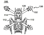
도 1은 본 발명의 일 실시예에 따른 드론의 구성을 나타내는 사시도이고, 도 2는 본 발명의 일 실시예에 따른 드론의 구성을 나타내는 평면도이며, 도 3은 본 발명의 일 실시예에 따른 드론의 구성을 나타내는 측면도이다. 또한, 도 4는 본 발명의 일 실시예에 따른 드론의 구성을 나타내는 정면도이다. FIG. 1 is a perspective view showing the construction of a drone according to an embodiment of the present invention. FIG. 2 is a plan view showing the construction of a drone according to an embodiment of the present invention. Fig. 4 is a front view showing a configuration of a drones according to an embodiment of the present invention.
도 1을 참조하면, 본 발명의 일 실시예에 따른 드론(100)은 본체(110), 암(120), 추력 발생부(130)를 포함한다.Referring to FIG. 1, a
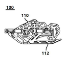
본체(110)는 소정의 크기를 갖는다. 본체(110)는 볼트 결합에 의해 조립되는 복수의 프레임을 포함할 수 있다. 여기서, 본체(110)의 조립에 사용되는 프레임은 경량화와 강도 보강을 위해 카본 재질인 것을 사용하는 것이 바람직하다. 또한, 본체(110)는 내부 구성 요소들에 대한 보호를 위해 이중 프레임 구조를 갖는 것이 바람직하다.The
본체(110)의 하부에는 드론의 이착륙시 발생되는 충격을 흡수하기 위한 랜딩 기어(112)가 배치된다. 랜딩 기어(112)는 이착륙시 발생되는 충격을 흡수할 수 있다면 사용자의 필요에 따라 다양한 형태로 이루어질 수 있다. A
본체(110)의 상부에는 본체(110) 내측으로 배치되는 수신기, 제어 회로 판넬 등을 보호하기 위한 보호 커버(114)가 배치될 수 있다. 여기서, 보호 커버(114)는 사용자의 필요에 따라 교체 가능하게 구성되는 것이 바람직하다. 본체(110)의 내측으로는 수신기(미도시), 제어 회로 판넬(미도시)과 같은 조종 계통 장비가 배치될 수 있다. A
드론(100)의 일단으로는 카메라 마운트(116)가 배치된다. 카메라 마운트(116)에 장착되는 카메라는 상하 좌우로 촬영 각도가 변화될 수 있다. 여기서, 카메라의 각도 변화는 드론을 조정하는 사용자가 소정의 조작에 의해 변화시킬 수 있다. A
본체(110)의 하부에는 비행에 필요한 전원을 공급하는 배터리가 배치되는 배터리 지그(118)가 배치될 수 있다. 배터리 지그(118)는 배터리의 형상에 대응하는 형상으로 이루어진다. 배터리 지그(118)는 본체(110) 하부에 배치되므로, 드론의 무게 중심이 하부에 위치되도록 하여 드론의 비행 안정성이 향상되도록 한다. A
암(120)은 본체(110)의 우측과 좌측의 전후로 각각 소정의 길이로 복수개가 돌출된다. 본 실시예에서 암(120)은 개수는 4개이고, 각각의 암(120)은 2시 방향, 4시 방향, 8시 방향, 10시 방향으로 각각 돌출되지만, 사용자의 필요에 따라 암(120)의 개수는 증가될 수 있고, 암(120)의 개수 증가에 따라 돌출 방향도 다양하게 변경될 수 있다. 또한, 암(120)의 돌출 길이도 사용자의 필요에 따라 다양하게 변경될 수 있다. A plurality of
추력 발생부(130)는 암(120)의 단부에 각각 배치되어, 비행에 필요로 하는 추력을 발생시킨다. 여기서, 추력 발생부(130)는 암(120)의 단부에 상하로 각각 배치된다. 암(120)의 단부 상하에 추력 발생부(130)가 각각 발생되므로, 본 실시예에 따른 드론(100)은 모두 8개의 추력 발생부(130)를 포함한다. 추력 발생부(130)의 증가에 의해, 추력이 증가되고 비행 스피드가 증가될 수 있다. The
추력 발생부(130)는 모터(M)와 모터 마운트(132)를 포함한다. The
모터(M)는 배터리(미도시)에서 공급되는 전원에 의해 소정의 회전수로 회전 동작한다. 도면에서, 모터(M)는 단일개로 도시되어 있으나, 이는 도면의 복잡화를 방지하기 위한 것으로서, 추력 발생부(130) 각각에는 모터(M)가 배치되는 것으로 이해되어야 한다. The motor M rotates at a predetermined number of revolutions by a power source supplied from a battery (not shown). It should be understood that the motor M is disposed in each of the
모터(M)의 회전축 상에는 프로펠라(propeller; 134)가 배치된다. 여기서, 모터(M)와 프로펠라 사이에는 소정의 감속 기어가 배치될 수 있다. A
도 1 내지 도 3에서는 도면의 간략화를 위해 프로펠라의 도시를 생략하였으나, 도 4에는 추력 발생부(130)가 상하로 배치되는 것을 나타내기 위하여 프로펠라를 도시하였다. In FIGS. 1 to 3, the illustration of the propeller is omitted for the sake of simplicity, but FIG. 4 shows a propeller for indicating that the
모터 마운트(132)는 모터가 고정되고, 모터(M)의 동작 중 발생되는 진동에 대한 내구성을 갖고, 모터 동작 발생하는 진동을 흡수한다. The
여기서, 모터 마운트(132)는 암(120)과 일체로 형성되도록 하여, 진동을 흡수 능력이 향상되도록 하고, 이에 따라 모터 진동에 의한 비행 성능 저하가 방지된다. 여기서, 추력 발생부(130)는 상하로 배치되므로, 모터 마운트(132)를 단일개로 배치한 후 모터 마운트(132)의 상부와 하부에 각각 모터(M)를 각각 연결하여 부품 구성수를 줄일 수도 있다. Here, the
본 발명은, 비행 방향의 상황을 촬영하는 카메라의 각도 조절이 가능하게 구성되어 비행 중 비행 방향의 상황을 알기 쉽게 한다. The present invention makes it possible to adjust the angle of the camera for photographing the situation in the flight direction, thereby making it easy to understand the situation in the flight direction during the flight.
본 발명은 도면에 도시된 실시예를 참고로 설명되었으나 이는 예시적인 것에 불과하며, 본 기술 분야의 통상의 지식을 가진 자라면 이로부터 다양한 변형 및 균등한 다른 실시예가 가능하다는 점을 이해할 것이다. 따라서, 본 발명의 진정한 기술적 보호 범위는 첨부된 특허청구범위의 기술적 사상에 의하여 정해져야 할 것이다.While the present invention has been described with reference to exemplary embodiments, it is to be understood that the invention is not limited to the disclosed exemplary embodiments, but, on the contrary, is intended to cover various modifications and equivalent arrangements included within the spirit and scope of the appended claims. Accordingly, the true scope of the present invention should be determined by the technical idea of the appended claims.
100: 드론
110: 본체
120: 암
130: 추력 발생부100: Drones
110:
120: Cancer
130:
Claims (4)
하부에 배터리 지그가 배치되고 상부로는 신호를 수신받는 수신기와 비행 제어 회로부가 배치되는 이중 프레임 구조의 본체;
상기 본체에서 복수로 돌출되는 암;
상기 암의 단부에 상하로 각각 배치되는 추력 발생부;
상기 본체의 전방으로 배치되고 상하 좌우로 각도 조정이 가능한 카메라;
를 포함하는 드론.A dron for receiving a control signal transmitted from a remote point and performing flight,
A body of a double frame structure in which a battery jig is disposed at a lower portion and a receiver and a flight control circuit portion are disposed at an upper portion;
An arm protruding from the main body in plurality;
A thrust generating unit disposed on the end of the arm, the thrust generating unit being vertically disposed;
A camera disposed in front of the main body and capable of adjusting the angle of up and down and left and right;
Lt; / RTI >
상기 본체 상부에는, 상기 수신기와 상기 비행 제어 회로부를 보호하는 보호 커버가 교체 가능하게 배치되는 드론.The method according to claim 1,
And a protective cover for protecting the receiver and the flight control circuit portion is replaceably arranged on the upper portion of the main body.
상기 추력 발생부는,
상기 배터리의 전원을 공급받아 동작하는 모터와,
상기 암과 일체로 형성되어 상기 암의 단부에 상기 모터가 고정되도록 하는 모터 마운트를 포함하는 드론.The method according to claim 1,
The thrust generating unit may include:
A motor that is operated by receiving power from the battery;
And a motor mount integrally formed with the arm to fix the motor to the end of the arm.
상기 추력 발생부는, 상기 모터 마운트를 공유하는 드론. The method of claim 3,
Wherein the thrust generating portion shares the motor mount.
Priority Applications (1)
| Application Number | Priority Date | Filing Date | Title |
|---|---|---|---|
| KR1020160068233A KR20170136309A (en) | 2016-06-01 | 2016-06-01 | Drone |
Applications Claiming Priority (1)
| Application Number | Priority Date | Filing Date | Title |
|---|---|---|---|
| KR1020160068233A KR20170136309A (en) | 2016-06-01 | 2016-06-01 | Drone |
Publications (1)
| Publication Number | Publication Date |
|---|---|
| KR20170136309A true KR20170136309A (en) | 2017-12-11 |
Family
ID=60943554
Family Applications (1)
| Application Number | Title | Priority Date | Filing Date |
|---|---|---|---|
| KR1020160068233A KR20170136309A (en) | 2016-06-01 | 2016-06-01 | Drone |
Country Status (1)
| Country | Link |
|---|---|
| KR (1) | KR20170136309A (en) |
Cited By (1)
| Publication number | Priority date | Publication date | Assignee | Title |
|---|---|---|---|---|
| KR20200106197A (en) * | 2018-01-17 | 2020-09-11 | 그리프 에이비에이션 에이에스 | Drone |
-
2016
- 2016-06-01 KR KR1020160068233A patent/KR20170136309A/en unknown
Cited By (1)
| Publication number | Priority date | Publication date | Assignee | Title |
|---|---|---|---|---|
| KR20200106197A (en) * | 2018-01-17 | 2020-09-11 | 그리프 에이비에이션 에이에스 | Drone |
Similar Documents
| Publication | Publication Date | Title |
|---|---|---|
| KR101820420B1 (en) | Hybrid system of drone | |
| EP3097014B1 (en) | Multicopters with variable flight characteristics | |
| US7273195B1 (en) | Vertical lift craft | |
| CN104527979B (en) | Space base teargas bullet automatic feeder | |
| US20140117149A1 (en) | Tetra-Propeller Aircraft | |
| EP2772429A1 (en) | Four-rotor aircraft | |
| US20140175214A1 (en) | Vtol_twin_propeller_attitude_control_air_vehicle | |
| KR101804531B1 (en) | Multicopter having multi-layered rotating wing unit | |
| US8844860B2 (en) | Foldable rise and stare vehicle | |
| JP2013531573A (en) | Reconfigurable battery-powered drone system | |
| RU2567496C1 (en) | Multirotor vtol drone | |
| WO2010005203A3 (en) | Rotational bottom blade type flight vehicle | |
| KR101552486B1 (en) | Multifunction connected flywheel propulsion module, using the same the puzzle assembled multicopter operating methods and system. | |
| KR101746945B1 (en) | Manless flight device includes launcher for fire-fighting | |
| CN105346709B (en) | A kind of multi-rotor aerocraft of deformable combination | |
| KR20170064399A (en) | Drone Equipped With Multi-Function Landing Skid | |
| CN108423153A (en) | Modularized micro unmanned plane | |
| KR20170136309A (en) | Drone | |
| KR20200061781A (en) | Multi purpose extension type unmanned aerial vehicle | |
| KR101621210B1 (en) | Tilt-Cube-In-Wing Unmanned Aerial Vehicle | |
| CN104503458A (en) | Micro individual combat unmanned plane system | |
| KR101816285B1 (en) | Easy assembling drone | |
| KR101642396B1 (en) | The drone with the landing device in the motor shaft | |
| KR20170136308A (en) | Drone | |
| CN105366065A (en) | Anti-falling unmanned aerial vehicle |