EP3738907B1 - Regallagersystem mit mehrebenen lagerregalen - Google Patents
Regallagersystem mit mehrebenen lagerregalen Download PDFInfo
- Publication number
- EP3738907B1 EP3738907B1 EP20173056.1A EP20173056A EP3738907B1 EP 3738907 B1 EP3738907 B1 EP 3738907B1 EP 20173056 A EP20173056 A EP 20173056A EP 3738907 B1 EP3738907 B1 EP 3738907B1
- Authority
- EP
- European Patent Office
- Prior art keywords
- storage
- conveyor
- vertical lift
- lift
- rack
- Prior art date
- Legal status (The legal status is an assumption and is not a legal conclusion. Google has not performed a legal analysis and makes no representation as to the accuracy of the status listed.)
- Active
Links
Images


Classifications
-
- B—PERFORMING OPERATIONS; TRANSPORTING
- B65—CONVEYING; PACKING; STORING; HANDLING THIN OR FILAMENTARY MATERIAL
- B65G—TRANSPORT OR STORAGE DEVICES, e.g. CONVEYORS FOR LOADING OR TIPPING, SHOP CONVEYOR SYSTEMS OR PNEUMATIC TUBE CONVEYORS
- B65G1/00—Storing articles, individually or in orderly arrangement, in warehouses or magazines
- B65G1/02—Storage devices
- B65G1/04—Storage devices mechanical
- B65G1/06—Storage devices mechanical with means for presenting articles for removal at predetermined position or level
- B65G1/065—Storage devices mechanical with means for presenting articles for removal at predetermined position or level with self propelled cars
-
- B—PERFORMING OPERATIONS; TRANSPORTING
- B65—CONVEYING; PACKING; STORING; HANDLING THIN OR FILAMENTARY MATERIAL
- B65G—TRANSPORT OR STORAGE DEVICES, e.g. CONVEYORS FOR LOADING OR TIPPING, SHOP CONVEYOR SYSTEMS OR PNEUMATIC TUBE CONVEYORS
- B65G1/00—Storing articles, individually or in orderly arrangement, in warehouses or magazines
- B65G1/02—Storage devices
- B65G1/04—Storage devices mechanical
- B65G1/0485—Check-in, check-out devices
-
- B—PERFORMING OPERATIONS; TRANSPORTING
- B65—CONVEYING; PACKING; STORING; HANDLING THIN OR FILAMENTARY MATERIAL
- B65G—TRANSPORT OR STORAGE DEVICES, e.g. CONVEYORS FOR LOADING OR TIPPING, SHOP CONVEYOR SYSTEMS OR PNEUMATIC TUBE CONVEYORS
- B65G1/00—Storing articles, individually or in orderly arrangement, in warehouses or magazines
- B65G1/02—Storage devices
- B65G1/04—Storage devices mechanical
- B65G1/137—Storage devices mechanical with arrangements or automatic control means for selecting which articles are to be removed
- B65G1/1373—Storage devices mechanical with arrangements or automatic control means for selecting which articles are to be removed for fulfilling orders in warehouses
- B65G1/1378—Storage devices mechanical with arrangements or automatic control means for selecting which articles are to be removed for fulfilling orders in warehouses the orders being assembled on fixed commissioning areas remote from the storage areas
Definitions
- the invention relates to a shelf storage system with multi-level storage shelves that define an aisle between them, in which shuttles travel along the shelves in the storage levels as operating devices for storing and retrieving loads from the shelves, wherein at least one vertical lift is arranged within the base area of the shelves of an aisle in such a way that the shuttles can travel past the vertical lift on rails along the front sides of the shelves facing the aisle and can deliver or pick up loads via a buffer conveyor arranged next to the vertical lift, wherein the buffer conveyor conveys loads to the lift or takes them from the lift, according to claim 1.
- Figure 8 of the AT 516231 A1 discloses a buffer conveyor which is also reversible and is arranged on one side next to a lift with a reversible lift conveyor.
- the object of the present invention is to simplify such a storage system, in particular in the storage connection level(s), and thus to save space.
- the buffer conveyor is no longer arranged on both sides of the lift, but only on one side next to it as a double conveyor and in turn has a longitudinal division such that one longitudinal half conveys towards the lift and the other longitudinal half away from the lift.
- the buffer conveyor is therefore replaced by two conveyors that are half as narrow as the double conveyor, so that when placed next to each other they do not require any more space.
- the width of the two (or more) conveyors arranged next to each other depends minimally on the width of the goods to be conveyed and as a maximum limiting element on the space available, e.g. shelf depth.
- the two (or more) conveyors can be installed within these parameters.
- the double conveyor is a multiple conveyor with more than two parallel conveyors, e.g. triple or quadruple.
- the lift has a reversible lift conveyor.
- one or more lifts can be arranged to the right or left of the rack aisle. These can be arranged both at the ends and in the shelves along the rack aisle.
- the double conveyors are therefore aligned with the halves of the lift or lift conveyor in the direction of the longitudinal alignment of the rack or aisle in the sense that the halves of the double conveyor are aligned with the "narrow" (virtual) halves of the lift when these at the same height.
- the lift or its lift conveyor can not only be virtually divided, but can also physically have two separately driven halves (see below).
- the buffer conveyors can be arranged on both sides - as is known - or alternatively, in line with the innovation, also on one side.
- buffer conveyors can also be arranged in the supply and/or disposal line.
- the shuttle can deposit the loads at suitable depths on the buffer conveyor or take them from there, e.g. using the well-known telescopic arms. Loads can also be picked up or delivered from or to the buffer conveyor in parallel by several shuttles on the same storage level.
- picking stations can also be connected via the double conveyor using a slim and therefore space-saving route (directly to the aisles or shelves).
- the lift conveyor is divided virtually or physically by guides in accordance with the double conveyor division. Also conceivable, but not according to the invention, is the use of two parallel, independent conveyors.
- Inclined roller conveyors can be arranged between the lift conveyor and the double conveyor in order to align the loads to the desired longitudinal half depending on the conveying direction.
- the figures show a shelving system, designated as a whole with 1, with multi-level storage racks 2 defining an aisle 3 between them, in which shuttles travel along the racks in the storage levels as operating devices for storing and retrieving loads L into the racks.
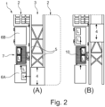
- At least one vertical lift 7 is arranged in such a way that the shuttles 4 can travel past the vertical lift 7 on rails 5 along the front sides of the shelves facing the aisle 3 and can each deliver cargo via a buffer conveyor 6A arranged next to the vertical lift 7 or pick up cargo via a buffer conveyor 6B arranged on the other side, as shown in Figure 2 shown in Figures A and B.
- the vertical lift 7 is arranged between two buffer conveyors 6A, B within the rack 2.
- the respective buffer conveyor 6A, B conveys load L to the lift 7 or takes over load from the lift 7. This decouples the movement of the lift 7 from that of the shuttle 4.
- the system is designed in such a way that in the bearing connection level (cf. Figure 1 ) goods L can only be loaded and picked up on one side I of the lift 7.
- the storage conveyor 8A and the retrieval conveyor 8B of the storage connection level are both designed on one side next to the lift 7 as a single double conveyor 9 separated by a guide 11.
- the double conveyor 9 has a Longitudinal division such that the storage conveyor 8A forming one longitudinal half conveys towards the lift 7 and the removal conveyor 8B forming the other longitudinal half conveys away from the lift 7 in the same plane.
- the lift 7 has a reversible lift conveyor 10 so that the load L can also be transported in the connection level of the Figure 1 can be picked up and released from one side, as shown in the figure in illustrations A, B and C.
- the lift conveyor 10 is in this case only virtually divided according to the double conveyor division, similar to the buffer conveyors 6A, 6B in the storage level.
- a shuttle 4 may therefore only deliver the load L once deep onto the buffer conveyor 6A and pick it up twice as deep from the buffer conveyor 6B.
- a picking station 12 is connected by means of a double conveyor 9 directly to an aisle 3 or to the one shelf 2 with the lift 7.
- the picking stations 12 are supplied with and removed from loads L by the lift 7 via the double conveyor 9.
- the picking station 12 is equipped with an order conveyor 13, on which the order containers are fed and also removed after processing. become.
- the order removal conveyor 13* is only used for removal after order containers have been processed.
- the order picking stations 12* share a common order container feed conveyor 14 arranged centrally between them.
Landscapes
- Engineering & Computer Science (AREA)
- Mechanical Engineering (AREA)
- Warehouses Or Storage Devices (AREA)
Description
- Die Erfindung betrifft ein Regallagersystem mit mehrebenen Lagerregalen, die zwischen sich eine Gasse definieren, in der in den Lagerebenen Shuttles entlang der Regale als Bediengeräte zum Ein- und Auslagern von Ladegütern in die Regale fahren, wobei innerhalb der Grundfläche der Regale einer Gasse mindestens ein Vertikallift so angeordnet ist, dass die Shuttles auf Schienen entlang der der Gasse zugewandten Regalvorderseiten an dem Vertikallift vorbeifahren können und über einen neben dem Vertikallift angeordneten Pufferförderer Ladegut abgeben bzw. aufnehmen können, wobei der Pufferförderer Ladegut an den Lift weiterfördert bzw. vom Lift übernimmt, nach Anspruch 1.
- Figur 8 der
AT 516231 A1 - Aus der
EP 2 794 431 B1 , welche ein Regallagersystem nach dem Oberbegriff des Anspruchs 1 offenbart, ist es bekannt, in einem Regallagersystem mit Lagerregalen die zwischen sich eine Gasse definieren, in der in den Lagerebenen Shuttles entlang der Regale als Bediengeräte fahren, vertikal Lifte innerhalb der Regale so anzuordnen, dass die Shuttles an diesen einerseits vorbeifahren können und andererseits über beidseitig der Lifte daneben angeordneten Pufferförderern Ladegut abgeben bzw. aufnehmen können, das an den Lift weitergefördert wird bzw. vom Lift stammt. In einer Lager-Anbindungsebene, d. h. der Zuführung zu dem Lager bzw. Abführung von dem Lager, wird der Lift dagegen zwischen einem Einlagerungsförderer und einem Auslagerungsförderer positioniert. Somit ist es möglich, dass einerseits die Shuttles vom Betrieb des Lifts entkoppelt werden und andererseits der Lift gleichzeitig Ladegüter aufnehmen und abgeben kann. - Demgegenüber besteht die Aufgabe der vorliegenden Erfindung darin, ein solches Lagersystem insbesondere in der oder den Lager-Anbindungsebene(n) zu vereinfachen und somit Platz zu sparen.
- Diese Aufgabe wird durch das in Anspruch 1 wiedergegebene Regallagersystem gelöst.
- Vorteilhafte Ausgestaltungen ergeben sich aus den Unteransprüchen.
- Erfindungsgemäß ist erkannt worden, dass, wenn lediglich auf einer Seite des Lifts in einer Ebene Ladegüter bzw. Ladehilfsmittel aufgegeben und auch aufgenommen werden, eine platzsparende Anordnung möglich ist, die sich auch in einer einfacheren Anbindung von Kommissionierplätzen in der Lager-Anbindungsebene äußert. Zudem werden kürzere Zykluszeiten ermöglicht, was zu höherer Anlagenleistung führt.
- Mit anderen Worten, der Pufferförderer ist nicht mehr beidseitig des Liftes, sondern nur noch einseitig daneben als Doppelförderer angeordnet und weist im Gegenzug eine Längsteilung derart auf, dass eine Längshälfte zum Lift hin und die andere Längshälfte vom Lift wegfördert.
- Dies kann parallel erfolgen, d.h. die Hälften des Doppelförderers sind unabhängig voneinander.
- Der Pufferförderer ist also durch zwei halb so schmale Förderer als Doppelförderer ersetzt, so dass diese nebeneinander platziert keinen größeren Platzbedarf erzeugen. Die Breite der zwei (oder mehr) nebeneinander angeordneten Förderer hängt minimal von der Fördergutbreite und als max. limitierendes Element von dem zur Verfügung stehenden Platz, z. B. Regaltiefe ab. Innerhalb dieser Parameter können die zwei (oder mehr) Förderer eingebaut werden.
- Denkbar ist also auch, dass der Doppelförderer ein Mehrfachförderer mit mehr als zwei parallelen Förderern ist, z. B. dreifach oder vierfach.
- Ermöglicht wird dies unter anderem durch die Ausrichtung der Ladegüter bzw. Ladehilfsmittel mit der Schmalseite in Förderrichtung oder alternativ der alleinigen Verwendung von schmalen Ladegütern bzw. schmalen Ladehilfsmitteln für die Ladegüter, so dass sie weniger Breite benötigen.
- Erfindungsgemäß weist der Lift einen reversierbaren Liftförderer auf. In einer Regalgasse können ein oder mehrere Lifte rechts bzw. links von der Regalgasse angeordnet werden. Diese können sowohl an den Enden als auch in den Regalen entlang der Regalgasse angeordnet sein.
- Die Doppelförderer fluchten also mit den Hälften des Lifts bzw. Liftförderers in Richtung der Längsausrichtung des Regals bzw. Gasse in dem Sinne, dass die Hälften des Doppelförderers mit den "schmalen" (virtuellen) Hälften des Lifts fluchten, wenn sich diese auf gleicher Höhe befinden.
- Der Lift bzw. dessen Liftförderer können nicht nur virtuell geteilt sein, sondern auch physikalisch zwei getrennt angetriebene Hälften aufweisen (siehe unten).
- In den Lagerebenen können die Pufferförderer dagegen - wie bekannt - beidseitig angeordnet sein oder alternativ im Sinne der Neuerung ebenfalls nur einseitig. In der oder den Lager-Anbindungsebene(n) können ebenfalls Pufferförderer in der Ver- und/oder Entsorgungsstrecke angeordnet sein.
- In beiden Fällen kann das Shuttle die Ladegüter in geeignete Tiefen auf dem Pufferförderer ablegen bzw. von dort übernehmen, z. B. mittels der bekannten Teleskoparme. Eine Aufnahme bzw. Abgabe von Ladegütern von bzw. an die Pufferförderer kann auch parallel durch mehrere Shuttles der gleichen Lagerebene erfolgen.
- In der Lager-Anbindungsebene können so auch Kommissionierstationen mittels schlanker und somit platzsparender Streckenführung (direkt an die Gassen bzw. Regale) über den Doppelförderer angeschlossen werden.
- Denkbar ist es auch, dass die Längshälften des Doppelförderers mittels einer Führung getrennt sind.
- Der Liftförderer ist erfindungsgemäß virtuell oder physikalisch durch Führungen entsprechend der Doppelfördererteilung geteilt. Auch denkbar und nicht erfindungsgemäß ist der Einsatz zweier paralleler unabhängiger Förderer.
- Zwischen dem Liftförderer und dem Doppelförderer können Schrägrollenförderer angeordnet sein, um die Ladegüter je nach Förderrichtung auf die gewünschte Längshälfte auszurichten.
- Weitere Details der Erfindung ergeben sich aus der nachfolgenden Beschreibung von Ausführungsbeispielen anhand der Zeichnung, in der
-
Fig. 1 eine schematische Ansicht auf eine Ein- und Auslagerungsebene eines Lagers im Bereich der Anbindung eines Lagerlifts an die Ein- und Auslagerfördertechnik; -
Fig. 2 eine schematische Ansicht auf eine Lagerebene des Lagers ausFigur 1 im Bereich des Lagerlifts und -
Fig. 3 eine schematische Ansicht auf eine Kommissionierebene des Lagers ausFigur 1 im Bereich der Anbindung des Lagerlifts an Kommissionierstationen zeigen. - In den Figuren ist ein als Ganzes mit 1 bezeichnetes Regallagersystem mit mehrebenen Lagerregalen 2, die zwischen sich eine Gasse 3 definieren, in der in den Lagerebenen Shuttles entlang der Regale als Bediengeräte zum Ein- und Auslagern von Ladegütern L in die Regale fahren gezeigt.
- Innerhalb der Grundfläche der Regale 2 einer Gasse 3 ist mindestens ein Vertikallift 7 so angeordnet, dass die Shuttles 4 auf Schienen 5 entlang der der Gasse 3 zugewandten Regalvorderseiten an dem Vertikallift 7 vorbeifahren können und jeweils über einen neben dem Vertikallift 7 angeordneten Pufferförderer 6A Ladegut abgeben bzw. auf der anderen Seite angeordneten Pufferförderer 6B Ladegut aufnehmen können, wie dies in
Figur 2 in den Abbildungen A und B dargestellt ist. - Mit anderen Worten in der Lagerebene (
Figur 2 ) ist der Vertikallift 7 zwischen zwei Pufferförderern 6A, B innerhalb des Regals 2 angeordnet. - Der jeweilige Pufferförderer 6A, B fördert Ladegut L an den Lift 7 weiter bzw. übernimmt vom Lift 7 Ladegut. Dies entkoppelt die Bewegung des Lifts 7 von derjenigen der Shuttle 4.
- Erfindungsgemäß ist das System derart ausgestaltet, dass in der Lager-Anbindungsebene (vgl.
Figur 1 ) lediglich auf einer Seite I des Lifts 7 Ladegüter L aufgegeben und auch aufgenommen werden. - Dazu sind der Einlagerungsförderer 8A und der Auslagerungsförderer 8B der Lager-Anbindungsebene beide einseitig neben dem Lift 7 als ein einziger über eine Führung 11 getrennter Doppelförderer 9 ausgebildet.
- Der Doppelförderer 9 weist zur unabhängigen Förderung der Ladegüter L eine Längsteilung derart auf, dass eine Längshälfte bildender Einlagerungsförderer 8A zum Lift 7 hin und die andere Längshälfte bildender Auslagerungsförderer 8B vom Lift 7 weg in derselben Ebene fördert.
- Somit werden auf dem Doppelförderer 9 Ladegüter L mit der Schmalseite S in Förderrichtung F befördert.
- Es ist somit möglich in der Aufstandsfläche nur eines Regals 2 sowohl eine Ein- als auch Auslagerung zu bewerkstelligen. Bisher üblich ist die Verwendung von einem Regal pro Gasse als Einlagerungsanbindung und dem anderen Regal als Auslagerungsanbindung.
- Der Lift 7 weist einen reversierbaren Liftförderer 10 auf, so dass die Ladegüter L auch in der Anbindungsebene der
Figur 1 einseitig aufnehmbar und abgebbar sind, wie dies anhand der Figur in den Darstellungen A, B und C gezeigt ist. - Der Liftförderer 10 ist vorliegend nur virtuell entsprechend der Doppelfördererteilung geteilt, ähnlich wie die Pufferförderer 6A, 6B in der Lagerebene.
- Ein Shuttle 4 darf die Ladegüter L also nur einfach tief auf den Pufferförderer 6A abgeben und dagegen doppelt so tief von dem Pufferförderer 6B aufnehmen.
- In der in
Figur 3 dargestellten Variante A ist in einer Lager-Anbindungsebene (Kommissionier-Ebene) jeweils eine Kommissionierstation 12 mittels eines Doppelförderers 9 direkt an eine Gasse 3 bzw. an das eine Regal 2 mit dem Lift 7 angeschlossen. - In der in
Figur 3 dargestellten Variante B sind dagegen in einer Lager-Anbindungsebene (Kommissionier-Ebene) jeweils zwei Kommissionierstationen 12* mittels jeweils eines Doppelförderers 9 direkt an eine Gasse 3 bzw. jeweils an eines der Regale 2 mit dem Lift 7 angeschlossen. - In beiden Fällen werden die Kommissionierstationen 12 von dem Lift 7 über den Doppelförderer 9 mit Ladegütern L ver- und entsorgt.
- In der Variante A ist die Kommissionierstation 12 mit einem Auftragsabförderer 13 ausgestaltet, auf dem Auftragsbehälter zu- und auch nach Abarbeitung abgefördert werden.
- In der Variante B dient der Auftragsabförderer 13* nur zur Abförderung nach Abarbeitung von Auftragsbehältern. Die Kommissionierstationen 12* teilen sich einen mittig zwischen ihnen angeordneten gemeinsamen Auftragsbehälterzuförderer 14.
-
- 1
- Regallagersystem
- 2
- Regal
- 3
- Gasse
- 4
- Shuttle
- 5
- Schiene
- 6A, 6B
- Pufferförderer
- 7
- Lift
- 8A
- Einlagerungsförderer
- 8B
- Auslagerungsförderer
- 9
- Doppelförderer
- 10
- Liftförderer
- 11
- Führung
- 12
- Kommisionierstation
- 13
- Auftragsabförderer
- 14
- Auftragsbehälterzuförderer
Claims (7)
- Regallagersystem (1) mit mehrebenen Lagerregalen (2), die zwischen sich eine Gasse (3) definieren, in der in den Lagerebenen Shuttles (4) entlang der Lagerregale (2) als Bediengeräte zum Ein- und Auslagern von Ladegütern (L) in die Lagerregale (2) fahren, wobei innerhalb der Grundfläche der Lagerregale (2) einer Gasse (3) mindestens ein Vertikallift (7) so angeordnet ist, dass die Shuttles (4) auf Schienen (5) entlang der der Gasse (3) zugewandten Regalvorderseiten an dem Vertikallift (7) vorbeifahren können und über einen neben dem Vertikallift (7) angeordneten Pufferförderer (6A, B) Ladegut (L) abgeben bzw. aufnehmen können, wobei der Pufferförderer (6A, B) Ladegut (L) an den Vertikallift (7) weiterfördert bzw. vom Vertikallift (7) übernimmt, wobei das System derart ausgestaltet ist, dass in einer im Regallagersystem enthaltenen Lager-Anbindungsebene lediglich auf einer Seite des Vertikallifts (7) Ladegüter (L) aufgegeben und auch aufgenommen werden, wobei der Vertikallift (7) einen reversierbaren Liftförderer (10) aufweist, dadurch gekennzeichnet, dass der Einlagerungsförderer (8A) und der Auslagerungsförderer (8B) der Lager-Anbindungsebene beide einseitig neben dem Vertikallift (7) als ein einziger Doppelförderer (9) in der Aufstandsfläche nur eines Lagerregals (2) angeordnet sind und dass der Doppelförderer (9) eine Längsteilung derart aufweist, dass eine Längshälfte zum Vertikallift (7) hin und die andere Längshälfte vom Vertikallift (7) weg in derselben Ebene fördert, und dass der Liftförderer virtuell oder physikalisch durch Führungen entsprechend der Doppelfördererteilung (9) geteilt ist und diese Teilung mit den Längshälften jeweils in der Lager-Anbindungsebene in Richtung der Längsausrichtung des Lagerregals (2) fluchtet, sodass die Hälften des Doppelförderers (9) mit den Hälften des Vertikallifts (7) fluchten, wenn sich diese auf gleicher Höhe befinden.
- Regallagersystem nach Anspruch 1, dadurch gekennzeichnet, dass der Doppelförderer (9) Ladegüter (L) mit der Schmalseite (S) in Förderrichtung (F) fördert.
- Regallagersystem nach einem der Ansprüche 1 oder 2, dadurch gekennzeichnet, dass der Doppelförderer (9) zwischen den Längshälften eine Führung (11) aufweist.
- Regallagersystem nach einem der vorhergehenden Ansprüche, dadurch gekennzeichnet, dass in der Lager-Anbindungsebene Kommissionierstationen (12) mittels des Doppelförderers (9) direkt an die Gassen (3) bzw. Lagerregale (2) angeschlossen sind.
- Verfahren zum Betrieb eines Regallagersystems nach einem der vorhergehenden Ansprüche, dadurch gekennzeichnet, dass lediglich auf einer Seite des Vertikallifts (7) in einer Lager-Anbindungsebene Ladegüter (L) in das Lagerregal (2) eingelagert bzw. daraus ausgelagert werden.
- Verfahren nach Anspruch 5, dadurch gekennzeichnet, dass in einzelnen LagerEbenen beidseitig des Vertikallifts (7) angeordnete Förderer eine gleichzeitige Be- und Entladung von Ladegütern (L), insbesondere entsprechend der Teilung ermöglichen.
- Verfahren nach Anspruch 5, dadurch gekennzeichnet, dass in einzelnen LagerEbenen einseitig des Vertikallifts (7) angeordnete Förderer eine gleichzeitige Be- und Entladung von Ladegütern (L), insbesondere entsprechend der Teilung ermöglichen.
Applications Claiming Priority (1)
| Application Number | Priority Date | Filing Date | Title |
|---|---|---|---|
| DE102019112642.8A DE102019112642A1 (de) | 2019-05-14 | 2019-05-14 | Regallagersystem mit mehrebenen Lagerregalen |
Publications (2)
| Publication Number | Publication Date |
|---|---|
| EP3738907A1 EP3738907A1 (de) | 2020-11-18 |
| EP3738907B1 true EP3738907B1 (de) | 2025-02-19 |
Family
ID=70553934
Family Applications (1)
| Application Number | Title | Priority Date | Filing Date |
|---|---|---|---|
| EP20173056.1A Active EP3738907B1 (de) | 2019-05-14 | 2020-05-05 | Regallagersystem mit mehrebenen lagerregalen |
Country Status (3)
| Country | Link |
|---|---|
| EP (1) | EP3738907B1 (de) |
| DE (1) | DE102019112642A1 (de) |
| ES (1) | ES3020283T3 (de) |
Families Citing this family (3)
| Publication number | Priority date | Publication date | Assignee | Title |
|---|---|---|---|---|
| CN114890036A (zh) * | 2022-06-22 | 2022-08-12 | 浙江凯乐士科技集团股份有限公司 | 一种仓储系统及货物出入库方法 |
| DE102022124753A1 (de) * | 2022-09-27 | 2024-03-28 | Gebhardt Fördertechnik GmbH | Shuttle-System und Verfahren zum Handhaben eines Ladungsträgers |
| DE102023114596B4 (de) | 2023-06-02 | 2025-07-03 | Dematic Gmbh | Regallagersystem mit mehrebenen Lagerregalen |
Family Cites Families (6)
| Publication number | Priority date | Publication date | Assignee | Title |
|---|---|---|---|---|
| AT512339B1 (de) * | 2011-12-21 | 2015-10-15 | Tgw Logistics Group Gmbh | Regallagersystem und verfahren zum betreiben desselben |
| DE102012107176A1 (de) * | 2012-08-06 | 2014-02-06 | Dematic Accounting Services Gmbh | Verfahren zum Bereitstellen von Transporteinheiten aus einem Lager |
| AT514710B1 (de) * | 2013-08-27 | 2015-06-15 | Tgw Logistics Group Gmbh | Automatisches Regallagersystem mit unabhängig voneinander verfahrbaren Förderfahrzeugen, sowie Verfahren hierzu |
| DE202014100476U1 (de) * | 2014-02-04 | 2014-03-13 | SSI Schäfer PEEM GmbH | Lagerregalanordnung mit stationären Vertikalförderern in stirnseitig angeordneter Vorzone |
| AT516231B1 (de) * | 2014-09-05 | 2016-09-15 | Tgw Mechanics Gmbh | Automatisiertes Regallagersystem und Verfahren zum sicheren Betreiben desselben |
| NL2015500B1 (nl) * | 2015-09-25 | 2017-04-20 | Vanderlande Ind Bv | Systeem voor het tijdelijk opslaan van producten zoals tubs al dan niet beladen met bagagestukken. |
-
2019
- 2019-05-14 DE DE102019112642.8A patent/DE102019112642A1/de not_active Withdrawn
-
2020
- 2020-05-05 ES ES20173056T patent/ES3020283T3/es active Active
- 2020-05-05 EP EP20173056.1A patent/EP3738907B1/de active Active
Also Published As
| Publication number | Publication date |
|---|---|
| DE102019112642A1 (de) | 2020-11-19 |
| EP3738907A1 (de) | 2020-11-18 |
| ES3020283T3 (en) | 2025-05-22 |
Similar Documents
| Publication | Publication Date | Title |
|---|---|---|
| EP2794433B1 (de) | Kommissionieranlage sowie verfahren zum kommissionieren von artikeln | |
| DE10136354B4 (de) | Verfahren und Anlage zum Kommissionieren mit einem Behälterregal und zugeordnetem Regalbediengerät | |
| EP2477913B1 (de) | Verfahren und system zum ein- und auslagern von behältern in ein oder aus einem lagerregal mittels satellitenfahrzeug | |
| EP3925908B1 (de) | Automatisiertes lagersystem und verfahren zum lagern von hängewaren in diesem lagersystem | |
| EP0241824B1 (de) | Warenumschlagsanlage und Verfahren zu deren Betrieb | |
| EP2287093B1 (de) | Regallagersystem sowie ein Verfahren zum Betreiben eines Regallagersystems | |
| EP2327644B1 (de) | Kommissioniereinrichtung und Verfahren zum Kommissionieren | |
| EP2428467B1 (de) | Kommissioniersystem und Kommissionierverfahren | |
| WO2015024935A2 (de) | Speichervorrichtung für stapelbare behälter | |
| EP1716060A1 (de) | Verfahren und system zum bedienen eines regals in einer kommissionieranlage | |
| CH687522A5 (de) | Regalbediengeraet. | |
| DE102012025163A1 (de) | Verfahren und Vorrichtung zur Kommissionierung von Gütern | |
| EP3475212A1 (de) | Hochregallager mit darin zum ein- und auslagern oder umlagern von lagergut vorgesehenen regalbediengeräten | |
| EP3738907A1 (de) | Regallagersystem mit mehrebenen lagerregalen | |
| EP2746193B1 (de) | Regalfahrzeug, Regalbediengerät, Lager und entsprechendes Verfahren | |
| EP3224161B1 (de) | Verfahren zum betreiben eines fachbodenregallagers und entsprechendes fachbodenregallager | |
| WO2015150404A1 (de) | Logistiksystem und verfahren zur übergabe und/oder übernahme von waren zwischen einem fahrzeug und einem warenlager | |
| DE19712839B4 (de) | Kommissionierverfahren, Kommissionieranlage zur Durchführung des Verfahrens sowie Sortierpuffer hierfür | |
| AT523458A1 (de) | Lagersystem | |
| DE202004007004U1 (de) | Regallager mit Mehrebenen-Lagervorzone | |
| DE202020104955U1 (de) | Aufzug und Regalsystem | |
| DE102019134776B3 (de) | Verschieberegalanordnung und Verfahren zum Betreiben der Verschieberegalanordnung | |
| DE19601953C1 (de) | Verfahren und Vorrichtung zum Ein- und Auslagern von Fördergut | |
| DE10243919B4 (de) | Regallager zur Kommissionierung von Artikeln | |
| DE102023114596B4 (de) | Regallagersystem mit mehrebenen Lagerregalen |
Legal Events
| Date | Code | Title | Description |
|---|---|---|---|
| PUAI | Public reference made under article 153(3) epc to a published international application that has entered the european phase |
Free format text: ORIGINAL CODE: 0009012 |
|
| STAA | Information on the status of an ep patent application or granted ep patent |
Free format text: STATUS: THE APPLICATION HAS BEEN PUBLISHED |
|
| AK | Designated contracting states |
Kind code of ref document: A1 Designated state(s): AL AT BE BG CH CY CZ DE DK EE ES FI FR GB GR HR HU IE IS IT LI LT LU LV MC MK MT NL NO PL PT RO RS SE SI SK SM TR |
|
| AX | Request for extension of the european patent |
Extension state: BA ME |
|
| STAA | Information on the status of an ep patent application or granted ep patent |
Free format text: STATUS: REQUEST FOR EXAMINATION WAS MADE |
|
| 17P | Request for examination filed |
Effective date: 20210504 |
|
| RBV | Designated contracting states (corrected) |
Designated state(s): AL AT BE BG CH CY CZ DE DK EE ES FI FR GB GR HR HU IE IS IT LI LT LU LV MC MK MT NL NO PL PT RO RS SE SI SK SM TR |
|
| STAA | Information on the status of an ep patent application or granted ep patent |
Free format text: STATUS: EXAMINATION IS IN PROGRESS |
|
| 17Q | First examination report despatched |
Effective date: 20221205 |
|
| GRAP | Despatch of communication of intention to grant a patent |
Free format text: ORIGINAL CODE: EPIDOSNIGR1 |
|
| STAA | Information on the status of an ep patent application or granted ep patent |
Free format text: STATUS: GRANT OF PATENT IS INTENDED |
|
| RIC1 | Information provided on ipc code assigned before grant |
Ipc: B65G 1/137 20060101ALN20241107BHEP Ipc: B65G 1/06 20060101ALI20241107BHEP Ipc: B65G 1/04 20060101AFI20241107BHEP |
|
| INTG | Intention to grant announced |
Effective date: 20241115 |
|
| GRAS | Grant fee paid |
Free format text: ORIGINAL CODE: EPIDOSNIGR3 |
|
| GRAA | (expected) grant |
Free format text: ORIGINAL CODE: 0009210 |
|
| STAA | Information on the status of an ep patent application or granted ep patent |
Free format text: STATUS: THE PATENT HAS BEEN GRANTED |
|
| AK | Designated contracting states |
Kind code of ref document: B1 Designated state(s): AL AT BE BG CH CY CZ DE DK EE ES FI FR GB GR HR HU IE IS IT LI LT LU LV MC MK MT NL NO PL PT RO RS SE SI SK SM TR |
|
| REG | Reference to a national code |
Ref country code: GB Ref legal event code: FG4D Free format text: NOT ENGLISH |
|
| REG | Reference to a national code |
Ref country code: CH Ref legal event code: EP |
|
| REG | Reference to a national code |
Ref country code: IE Ref legal event code: FG4D Free format text: LANGUAGE OF EP DOCUMENT: GERMAN |
|
| REG | Reference to a national code |
Ref country code: DE Ref legal event code: R096 Ref document number: 502020010407 Country of ref document: DE |
|
| P01 | Opt-out of the competence of the unified patent court (upc) registered |
Free format text: CASE NUMBER: APP_7008/2025 Effective date: 20250211 |
|
| REG | Reference to a national code |
Ref country code: ES Ref legal event code: FG2A Ref document number: 3020283 Country of ref document: ES Kind code of ref document: T3 Effective date: 20250522 |
|
| REG | Reference to a national code |
Ref country code: NL Ref legal event code: FP |
|
| PGFP | Annual fee paid to national office [announced via postgrant information from national office to epo] |
Ref country code: NL Payment date: 20250521 Year of fee payment: 6 |
|
| PG25 | Lapsed in a contracting state [announced via postgrant information from national office to epo] |
Ref country code: RS Free format text: LAPSE BECAUSE OF FAILURE TO SUBMIT A TRANSLATION OF THE DESCRIPTION OR TO PAY THE FEE WITHIN THE PRESCRIBED TIME-LIMIT Effective date: 20250519 |
|
| PG25 | Lapsed in a contracting state [announced via postgrant information from national office to epo] |
Ref country code: FI Free format text: LAPSE BECAUSE OF FAILURE TO SUBMIT A TRANSLATION OF THE DESCRIPTION OR TO PAY THE FEE WITHIN THE PRESCRIBED TIME-LIMIT Effective date: 20250219 |
|
| PG25 | Lapsed in a contracting state [announced via postgrant information from national office to epo] |
Ref country code: PL Free format text: LAPSE BECAUSE OF FAILURE TO SUBMIT A TRANSLATION OF THE DESCRIPTION OR TO PAY THE FEE WITHIN THE PRESCRIBED TIME-LIMIT Effective date: 20250219 |
|
| PGFP | Annual fee paid to national office [announced via postgrant information from national office to epo] |
Ref country code: DE Payment date: 20250521 Year of fee payment: 6 |
|
| REG | Reference to a national code |
Ref country code: LT Ref legal event code: MG9D |
|
| PG25 | Lapsed in a contracting state [announced via postgrant information from national office to epo] |
Ref country code: IS Free format text: LAPSE BECAUSE OF FAILURE TO SUBMIT A TRANSLATION OF THE DESCRIPTION OR TO PAY THE FEE WITHIN THE PRESCRIBED TIME-LIMIT Effective date: 20250619 Ref country code: NO Free format text: LAPSE BECAUSE OF FAILURE TO SUBMIT A TRANSLATION OF THE DESCRIPTION OR TO PAY THE FEE WITHIN THE PRESCRIBED TIME-LIMIT Effective date: 20250519 |
|
| PG25 | Lapsed in a contracting state [announced via postgrant information from national office to epo] |
Ref country code: HR Free format text: LAPSE BECAUSE OF FAILURE TO SUBMIT A TRANSLATION OF THE DESCRIPTION OR TO PAY THE FEE WITHIN THE PRESCRIBED TIME-LIMIT Effective date: 20250219 |
|
| PG25 | Lapsed in a contracting state [announced via postgrant information from national office to epo] |
Ref country code: PT Free format text: LAPSE BECAUSE OF FAILURE TO SUBMIT A TRANSLATION OF THE DESCRIPTION OR TO PAY THE FEE WITHIN THE PRESCRIBED TIME-LIMIT Effective date: 20250620 Ref country code: LV Free format text: LAPSE BECAUSE OF FAILURE TO SUBMIT A TRANSLATION OF THE DESCRIPTION OR TO PAY THE FEE WITHIN THE PRESCRIBED TIME-LIMIT Effective date: 20250219 |
|
| PGFP | Annual fee paid to national office [announced via postgrant information from national office to epo] |
Ref country code: FR Payment date: 20250528 Year of fee payment: 6 |
|
| PG25 | Lapsed in a contracting state [announced via postgrant information from national office to epo] |
Ref country code: GR Free format text: LAPSE BECAUSE OF FAILURE TO SUBMIT A TRANSLATION OF THE DESCRIPTION OR TO PAY THE FEE WITHIN THE PRESCRIBED TIME-LIMIT Effective date: 20250520 Ref country code: BG Free format text: LAPSE BECAUSE OF FAILURE TO SUBMIT A TRANSLATION OF THE DESCRIPTION OR TO PAY THE FEE WITHIN THE PRESCRIBED TIME-LIMIT Effective date: 20250219 |
|
| PGFP | Annual fee paid to national office [announced via postgrant information from national office to epo] |
Ref country code: AT Payment date: 20250522 Year of fee payment: 6 |
|
| PG25 | Lapsed in a contracting state [announced via postgrant information from national office to epo] |
Ref country code: SE Free format text: LAPSE BECAUSE OF FAILURE TO SUBMIT A TRANSLATION OF THE DESCRIPTION OR TO PAY THE FEE WITHIN THE PRESCRIBED TIME-LIMIT Effective date: 20250219 |
|
| PG25 | Lapsed in a contracting state [announced via postgrant information from national office to epo] |
Ref country code: SM Free format text: LAPSE BECAUSE OF FAILURE TO SUBMIT A TRANSLATION OF THE DESCRIPTION OR TO PAY THE FEE WITHIN THE PRESCRIBED TIME-LIMIT Effective date: 20250219 |
|
| PGFP | Annual fee paid to national office [announced via postgrant information from national office to epo] |
Ref country code: ES Payment date: 20250630 Year of fee payment: 6 |
|
| PG25 | Lapsed in a contracting state [announced via postgrant information from national office to epo] |
Ref country code: DK Free format text: LAPSE BECAUSE OF FAILURE TO SUBMIT A TRANSLATION OF THE DESCRIPTION OR TO PAY THE FEE WITHIN THE PRESCRIBED TIME-LIMIT Effective date: 20250219 |
|
| PG25 | Lapsed in a contracting state [announced via postgrant information from national office to epo] |
Ref country code: IT Free format text: LAPSE BECAUSE OF FAILURE TO SUBMIT A TRANSLATION OF THE DESCRIPTION OR TO PAY THE FEE WITHIN THE PRESCRIBED TIME-LIMIT Effective date: 20250219 |
|
| PG25 | Lapsed in a contracting state [announced via postgrant information from national office to epo] |
Ref country code: EE Free format text: LAPSE BECAUSE OF FAILURE TO SUBMIT A TRANSLATION OF THE DESCRIPTION OR TO PAY THE FEE WITHIN THE PRESCRIBED TIME-LIMIT Effective date: 20250219 Ref country code: CZ Free format text: LAPSE BECAUSE OF FAILURE TO SUBMIT A TRANSLATION OF THE DESCRIPTION OR TO PAY THE FEE WITHIN THE PRESCRIBED TIME-LIMIT Effective date: 20250219 |
|
| PG25 | Lapsed in a contracting state [announced via postgrant information from national office to epo] |
Ref country code: RO Free format text: LAPSE BECAUSE OF FAILURE TO SUBMIT A TRANSLATION OF THE DESCRIPTION OR TO PAY THE FEE WITHIN THE PRESCRIBED TIME-LIMIT Effective date: 20250219 |
|
| PG25 | Lapsed in a contracting state [announced via postgrant information from national office to epo] |
Ref country code: SK Free format text: LAPSE BECAUSE OF FAILURE TO SUBMIT A TRANSLATION OF THE DESCRIPTION OR TO PAY THE FEE WITHIN THE PRESCRIBED TIME-LIMIT Effective date: 20250219 |
|
| REG | Reference to a national code |
Ref country code: DE Ref legal event code: R097 Ref document number: 502020010407 Country of ref document: DE |
|
| REG | Reference to a national code |
Ref country code: CH Ref legal event code: H13 Free format text: ST27 STATUS EVENT CODE: U-0-0-H10-H13 (AS PROVIDED BY THE NATIONAL OFFICE) Effective date: 20251223 |
|
| PLBE | No opposition filed within time limit |
Free format text: ORIGINAL CODE: 0009261 |
|
| STAA | Information on the status of an ep patent application or granted ep patent |
Free format text: STATUS: NO OPPOSITION FILED WITHIN TIME LIMIT |
|
| PG25 | Lapsed in a contracting state [announced via postgrant information from national office to epo] |
Ref country code: LU Free format text: LAPSE BECAUSE OF NON-PAYMENT OF DUE FEES Effective date: 20250505 |
|
| PG25 | Lapsed in a contracting state [announced via postgrant information from national office to epo] |
Ref country code: CH Free format text: LAPSE BECAUSE OF NON-PAYMENT OF DUE FEES Effective date: 20250531 |
|
| 26N | No opposition filed |
Effective date: 20251120 |
|
| GBPC | Gb: european patent ceased through non-payment of renewal fee |
Effective date: 20250519 |
|
| REG | Reference to a national code |
Ref country code: BE Ref legal event code: MM Effective date: 20250531 |
|
| PG25 | Lapsed in a contracting state [announced via postgrant information from national office to epo] |
Ref country code: MC Free format text: LAPSE BECAUSE OF FAILURE TO SUBMIT A TRANSLATION OF THE DESCRIPTION OR TO PAY THE FEE WITHIN THE PRESCRIBED TIME-LIMIT Effective date: 20250219 |
|
| PG25 | Lapsed in a contracting state [announced via postgrant information from national office to epo] |
Ref country code: GB Free format text: LAPSE BECAUSE OF NON-PAYMENT OF DUE FEES Effective date: 20250519 |
|
| PG25 | Lapsed in a contracting state [announced via postgrant information from national office to epo] |
Ref country code: IE Free format text: LAPSE BECAUSE OF NON-PAYMENT OF DUE FEES Effective date: 20250505 |
|
| PG25 | Lapsed in a contracting state [announced via postgrant information from national office to epo] |
Ref country code: BE Free format text: LAPSE BECAUSE OF NON-PAYMENT OF DUE FEES Effective date: 20250531 |