EP3738472B1 - Outil de réglage des pièces, en particulier des pieds de meubles - Google Patents
Outil de réglage des pièces, en particulier des pieds de meubles Download PDFInfo
- Publication number
- EP3738472B1 EP3738472B1 EP20174477.8A EP20174477A EP3738472B1 EP 3738472 B1 EP3738472 B1 EP 3738472B1 EP 20174477 A EP20174477 A EP 20174477A EP 3738472 B1 EP3738472 B1 EP 3738472B1
- Authority
- EP
- European Patent Office
- Prior art keywords
- adjustment tool
- head piece
- adjusting
- control device
- gear wheel
- Prior art date
- Legal status (The legal status is an assumption and is not a legal conclusion. Google has not performed a legal analysis and makes no representation as to the accuracy of the status listed.)
- Active
Links
- 238000005259 measurement Methods 0.000 claims 7
- 238000000034 method Methods 0.000 description 3
- 230000005540 biological transmission Effects 0.000 description 2
- 230000008878 coupling Effects 0.000 description 1
- 238000010168 coupling process Methods 0.000 description 1
- 238000005859 coupling reaction Methods 0.000 description 1
- 238000009434 installation Methods 0.000 description 1
Images


Classifications
-
- A—HUMAN NECESSITIES
- A47—FURNITURE; DOMESTIC ARTICLES OR APPLIANCES; COFFEE MILLS; SPICE MILLS; SUCTION CLEANERS IN GENERAL
- A47B—TABLES; DESKS; OFFICE FURNITURE; CABINETS; DRAWERS; GENERAL DETAILS OF FURNITURE
- A47B91/00—Feet for furniture in general
- A47B91/02—Adjustable feet
Definitions
- the invention relates to an adjusting tool for adjusting parts, in particular provided with a toothing, of base feet for furniture such as kitchen cabinet furniture or the like in the design according to the preamble of claim 1.
- Base feet for furniture such as kitchen cabinet furniture have a height-adjustable adjustment part in order to adapt the furniture exactly to the local installation conditions of the furniture.
- precise adjustment work must be carried out on site in order to precisely adjust and align the furniture to be set up using base feet or similar support parts.
- an adjusting tool is provided with a head piece having a receptacle and with a handle connected to the head piece, which has a rotatable control element at the end, via which the gear wheel protruding into the receiving space can be rotated via a non-rotatable connection.
- this gear meshes a toothing that is provided on the adjustment part, namely on an outer 360 ° collar, so that in the case of the base foot with the adjustment part arranged on it, this toothing is aligned essentially horizontally and therefore parallel to a mounting surface.
- the adjustment tool of the type mentioned is characterized in that the electromotive drive is connected to a measuring and control device, the measuring and control device determining the angle of inclination of a piece of furniture or the like supported on the base feet to the horizontal or another Orientation determined, with the electric motor drive being controlled as a function of the determined angle of inclination via the measuring and control device.
- the gear wheel of the head piece of the adjusting tool can be driven autonomously by the electric motor drive after it has been switched on and therefore used for an adjusting movement.
- the user no longer has to perform any twisting movement on a control unit, but only needs to operate a switch for one direction of rotation in order to be able to carry out the desired adjustment in one or the other direction.
- the electromotive drive is connected to the measuring and control device in such a way that the measuring and control device determines the angle of inclination of, for example, a piece of furniture to the horizontal, after which the measuring and control device controls the electromotive drive as a function of the inclination angle determined.
- An adjustment and thus a height compensation can thus take place in an automatic manner via this measuring and control device.
- the corresponding data and control commands can be transmitted over various transmission routes, e.g. B. via radio, USB, cable or the like ..
- the adjustment and thus height leveling usually only requires a short time, with readjustment by an operator is not necessary because the exact height setting is done automatically.
- the electromotive drive can advantageously be switched in such a way that it can rotate in opposite directions, that is, once in a clockwise direction and once in an anti-clockwise direction. It is particularly preferred if the toothing on the gear and also on the adjustment part is aligned exactly 90 ° differently from the known adjustment part, i.e. with a horizontal alignment of the adjustment tool in the vertical direction, with which the toothing of the gearwheel both in the case of the gearwheel of the head piece and the toothing on the adjustment part can be made much longer than in the known prior art, with the result that a decoupling of the adjustment tool and the adjustment part during an operating process is almost impossible. In addition, a larger gear coupling is to be implemented.
- not only one gear is provided in the head piece, but two, which are in turn driven by a common gear, so that a significantly larger gear contact surface can be made available via both gears on the adjustment part.
- the common toothed wheel can in turn be connected to a worm wheel via a further toothed wheel, which in turn is driven by the electric motor drive.
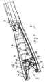
- 1 is an adjustment tool which has a handle 2, a head piece 4 and a receiving space 5 in the head piece.
- a receiving space 3 is provided within the head piece 4, in which an electric motor drive 6 is arranged. This is supplied with electrical energy by batteries (not shown) or an accumulator.
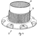
- the adjustment part V ( Fig. 4 ) is aligned with a vertically aligned toothing Z - based on a horizontal reference plane.
- This toothing Z can be of two gears 7 and 8, which are in the receptacle 5 ( Fig. 3 ) protrude, be driven. These two gears 7 and 8 are driven by a further gear 9.
- This further gear 9 is drivingly coupled to a further gear 11 via a connection 10.
- This further gear 11 is driven by a worm wheel 12, which in turn is driven by the electric motor drive.
- a holder part 13 is provided in the receptacle 5, which in the exemplary embodiment shown is designed as a stationary roller.
- a further holder part 14 is provided, which is also designed as a roller, but which is arranged to be pivotable and loaded by a spring 15, so that the roller 14 can initially give way to an adjustment part V with the aid of the spring 15 when the adjustment tool 1 is applied and is then pressed against the toothing Z with the aid of the spring 15 after placement.
- the electromotive drive 6 can now be switched on in order to move the adjustment part V via the thread G ( Fig. 4 ) to be adjusted on a base (not shown). This is possible with a simple operating effort.
- Fig. 5 shows the adjustment tool, which is basically constructed like the adjustment tool, as it is in the Figs. 1 to 4 is described.
- a cabinet 20 is shown, which can be placed on the floor of a building via adjustable feet 21 and which can be adjusted with regard to the height level via the adjustment tool 1.
- the control measuring device 22 is provided, which contains an electronic balance. This can be connected to the adjustment tool via various connecting plugs or via other transmission techniques. In the illustrated embodiment according to Fig. 5 should this be done via a radio link. A desired state can be set and also displayed via a keyboard.
- the electronic measuring and control unit controls the electric drive of the adjustment tool over the radio link so that this drive stops when the exact height adjustment has been made and the cabinet is set to an exact horizontal alignment.
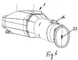
- the embodiment according to Fig. 6 shows on the adjustment tool 1 once again a socket 23 for receiving a plug for a cable connection between the control and measuring unit 22 and the adjustment tool 1. Furthermore, a connection to a PCT can be provided.
Claims (16)
- Outil de réglage (1) de pièces (V) dotées en particulier d'une denture (Z) de pieds de meubles comme par exemple des meubles de cuisine ou similaires avec un élément de tête (4) présentant un logement (5) pour la pièce (V) ainsi qu'au moins une roue dentée (7) pouvant être entraînée ainsi qu'avec une poignée (2) reliée à l'élément de tête (4), dans lequel un entraînement à moteur électrique (6) alimenté en énergie électrique par une batterie ou un accumulateur, par lequel la roue dentée (7) de l'élément de tête (4) peut être mise en mouvements de rotation pour le réglage de la pièce (V), est agencé dans un espace de logement (3) de la poignée (2) et/ou de l'élément de tête (4), caractérisé en ce que l'entraînement à moteur électrique (6) est relié à un dispositif de mesure et de commande (22), dans lequel le dispositif de mesure et de commande (22) détermine l'angle d'inclinaison d'un meuble reposant sur des pieds (21) ou similaire par rapport à l'horizontale ou à une autre orientation, dans lequel l'entraînement à moteur électrique (6) est commandé en fonction de l'angle d'inclinaison déterminé par le biais du dispositif de mesure et de commande (22).
- Outil de réglage (1) selon la revendication 1, caractérisé en ce que la roue dentée (7) de l'élément de tête (4) peut être mise en mouvements de rotation opposés par l'entraînement à moteur électrique (6) pour le réglage de la pièce (V).
- Outil de réglage (1) selon la revendication 1 ou 2, caractérisé en ce que les mouvements de rotation opposés sont activables par le biais d'un interrupteur (16) prévu sur la poignée (2).
- Outil de réglage (1) selon l'une quelconque des revendications 1 à 3, caractérisé en ce que les dents de la roue dentée (7) de l'élément de tête (4) sont orientées perpendiculairement à un plan médian longitudinal horizontal de l'outil de réglage (1) et ainsi parallèlement à l'extension en hauteur d'une pièce (V) d'un pied ou d'un élément d'appui similaire.
- Outil de réglage (1) selon l'une quelconque des revendications 1 à 4, caractérisé en ce que deux roues dentées (7, 8), qui sont entraînées par une roue dentée commune (9), sont prévues pour le réglage de la pièce (V) dans le logement (5) de l'élément de tête (4).
- Outil de réglage (1) selon la revendication 5, caractérisé en ce que la roue dentée commune (9) et/ou une autre roue dentée est reliée par le biais d'une liaison rigide (10) à une autre roue dentée (11), qui est entraînée par une roue à vis sans fin (17) par l'entraînement à moteur électrique (6).
- Outil de réglage (1) selon l'une quelconque des revendications 1 à 6, caractérisé en ce qu'au moins un support (13, 14) pour la fixation de la pièce (V) fait saillie dans le logement (3) de l'élément de tête (4).
- Outil de réglage (1) selon la revendication 7, caractérisé en ce que deux supports (13, 14) font saillie dans le logement (5) de l'élément de tête (4), dont un (13) est agencé de manière fixe et un autre (14) est supporté de manière élastique.
- Outil de réglage (1) selon la revendication 8, caractérisé en ce que le support (14) supporté de manière élastique est supporté par mouvement pivotant et est sollicité par un ressort (15).
- Outil de réglage (1) selon l'une quelconque des revendications 1 à 9, caractérisé en ce que l'espace de logement (3) pour l'entraînement à moteur électrique (6) et/ou un espace de logement pour au moins une batterie ou au moins un accumulateur peut être fermé par le biais d'un couvercle amovible.
- Outil de réglage (1) selon l'une quelconque des revendications 1 à 10, caractérisé en ce que l'outil de réglage (1) présente une prise de chargement pour le raccordement d'un chargeur pour la charge d'un accumulateur.
- Outil de réglage (1) selon la revendication 8, caractérisé en ce que les supports (13, 14) sont réalisés en tant que rouleaux.
- Outil de réglage (1) selon la revendication 1, caractérisé en ce que le dispositif de mesure et de commande (22) arrête l'entraînement à moteur électrique (6) pour le réglage (V) des pièces de pieds (21), dès qu'une compensation d'angle d'inclinaison a lieu.
- Outil de réglage (1) selon la revendication 1 ou 13, caractérisé en ce que l'entraînement à moteur électrique (6) est relié au dispositif de mesure et de commande (22) par le biais d'une liaison radio, comme par exemple une connexion Bluetooth, ou d'une connexion USB.
- Outil de réglage (1) selon la revendication 1, caractérisé en ce que le dispositif de mesure et de commande (22) électronique comprend un niveau à bulle électronique, qui est intégré dans un smartphone, une tablette, un PC, une montre intelligente ou un autre appareil de mesure.
- Outil de réglage (1) selon l'une quelconque des revendications 1, 13 à 15, caractérisé en ce que l'outil de réglage (V) est relié à son dispositif de mesure et de commande (22) avec un autre appareil électronique pour l'enregistrement et pour la communication de données de réglage de l'outil de réglage (1).
Priority Applications (2)
| Application Number | Priority Date | Filing Date | Title |
|---|---|---|---|
| PL20174477T PL3738472T3 (pl) | 2019-05-13 | 2020-05-13 | Narzędzie regulujące do części przestawnych zwłaszcza stopek cokołowych mebli |
| EP20214704.7A EP3827702B1 (fr) | 2019-05-13 | 2020-05-13 | Outil de réglage des pièces, en particulier des pieds de meubles |
Applications Claiming Priority (2)
| Application Number | Priority Date | Filing Date | Title |
|---|---|---|---|
| DE202019102684.7U DE202019102684U1 (de) | 2019-05-13 | 2019-05-13 | Verstellwerkzeug für Verstellteile von insbesondere Sockelfüßen für Möbel |
| DE202019105005.5U DE202019105005U1 (de) | 2019-09-10 | 2019-09-10 | Verstellwerkzeug für Verstellteile von insbesondere Sockelfüßen für Möbel |
Related Child Applications (2)
| Application Number | Title | Priority Date | Filing Date |
|---|---|---|---|
| EP20214704.7A Division-Into EP3827702B1 (fr) | 2019-05-13 | 2020-05-13 | Outil de réglage des pièces, en particulier des pieds de meubles |
| EP20214704.7A Division EP3827702B1 (fr) | 2019-05-13 | 2020-05-13 | Outil de réglage des pièces, en particulier des pieds de meubles |
Publications (2)
| Publication Number | Publication Date |
|---|---|
| EP3738472A1 EP3738472A1 (fr) | 2020-11-18 |
| EP3738472B1 true EP3738472B1 (fr) | 2021-09-15 |
Family
ID=70968709
Family Applications (2)
| Application Number | Title | Priority Date | Filing Date |
|---|---|---|---|
| EP20174477.8A Active EP3738472B1 (fr) | 2019-05-13 | 2020-05-13 | Outil de réglage des pièces, en particulier des pieds de meubles |
| EP20214704.7A Active EP3827702B1 (fr) | 2019-05-13 | 2020-05-13 | Outil de réglage des pièces, en particulier des pieds de meubles |
Family Applications After (1)
| Application Number | Title | Priority Date | Filing Date |
|---|---|---|---|
| EP20214704.7A Active EP3827702B1 (fr) | 2019-05-13 | 2020-05-13 | Outil de réglage des pièces, en particulier des pieds de meubles |
Country Status (3)
| Country | Link |
|---|---|
| EP (2) | EP3738472B1 (fr) |
| ES (2) | ES2926927T3 (fr) |
| PL (2) | PL3827702T3 (fr) |
Family Cites Families (2)
| Publication number | Priority date | Publication date | Assignee | Title |
|---|---|---|---|---|
| HUE051378T2 (hu) | 2013-10-11 | 2021-03-01 | Designerscope Ltd | Szekrény szintezõ eszköz |
| ITUB20153365A1 (it) * | 2015-09-03 | 2017-03-03 | Scilm Spa | Attrezzatura per la regolazione di piedi di supporto per mobili rispetto ad un piano di appoggio e dispositivo di supporto per mobili rispetto ad un piano di appoggio |
-
2020
- 2020-05-13 EP EP20174477.8A patent/EP3738472B1/fr active Active
- 2020-05-13 EP EP20214704.7A patent/EP3827702B1/fr active Active
- 2020-05-13 PL PL20214704.7T patent/PL3827702T3/pl unknown
- 2020-05-13 ES ES20214704T patent/ES2926927T3/es active Active
- 2020-05-13 ES ES20174477T patent/ES2901527T3/es active Active
- 2020-05-13 PL PL20174477T patent/PL3738472T3/pl unknown
Also Published As
| Publication number | Publication date |
|---|---|
| EP3827702A1 (fr) | 2021-06-02 |
| PL3827702T3 (pl) | 2022-11-28 |
| EP3827702B1 (fr) | 2022-06-15 |
| PL3738472T3 (pl) | 2022-04-04 |
| EP3738472A1 (fr) | 2020-11-18 |
| ES2901527T3 (es) | 2022-03-22 |
| ES2926927T3 (es) | 2022-10-31 |
Similar Documents
| Publication | Publication Date | Title |
|---|---|---|
| DE3036852C2 (de) | Vorrichtung zum Aufstellen eines Datensichtgerätes auf einer Arbeitsfläche | |
| DE202008001895U1 (de) | Wandhalteanordnung für einen Flachbildschirmmonitor | |
| DE60311792T2 (de) | Objekthalterung | |
| DE3801066A1 (de) | Einstellbares displaypaneel fuer tragbaren computer | |
| EP0917868B1 (fr) | Unité de commande pour actionner un plateau de table d'opération | |
| EP2729727A1 (fr) | Support pour tablette pc | |
| DE2628646C3 (de) | Vorrichtung zur Anzeige der Elevationsrichtung einer einstellbaren Antenne | |
| EP3738472B1 (fr) | Outil de réglage des pièces, en particulier des pieds de meubles | |
| DE973133C (de) | Stuhl fuer Zahnaerzte od. dgl. | |
| DE202019102684U1 (de) | Verstellwerkzeug für Verstellteile von insbesondere Sockelfüßen für Möbel | |
| DE102020118599B4 (de) | Verstellwerkzeug für Verstellteile von insbesondere Sockelfüßen für Möbel | |
| DE2652978B2 (de) | Fernverstellbarer Außenrückblickspiegel für Kraftfahrzeuge | |
| DE102015207736A1 (de) | Mobiles C-Bogen-Röntgengerät | |
| AT512414B1 (de) | Seitenzargenanordnung mit möbelauszugsführung | |
| EP1125534B1 (fr) | Système de cuisson avec une construction de tubes | |
| DE102008018929A1 (de) | Freistehende Bedienstelle zur Steuerung eines Bearbeitungszentrums | |
| DE102015002502A1 (de) | Vorrichtung zum Wenden von formstabilen Behältern | |
| DE102011078682B4 (de) | C-Bogen-Anlage | |
| DE3820749C1 (en) | Equipment support, in particular for the display unit and the keyboard of a data processing system | |
| DE2717022C2 (de) | Schleifvorrichtung für zahntechnische Zwecke | |
| WO2003023272A1 (fr) | Dispositif de suspension a cardan destine a un dispositif d'equilibrage de camera | |
| DE3818031A1 (de) | Vorrichtung zur halterung von werkzeugen | |
| DE4440338C2 (de) | Vorrichtung zum Halten und Führen von Handwerkzeugen | |
| DE3839742C2 (fr) | ||
| DE102009043835B3 (de) | Tragbarer Computer |
Legal Events
| Date | Code | Title | Description |
|---|---|---|---|
| PUAI | Public reference made under article 153(3) epc to a published international application that has entered the european phase |
Free format text: ORIGINAL CODE: 0009012 |
|
| STAA | Information on the status of an ep patent application or granted ep patent |
Free format text: STATUS: REQUEST FOR EXAMINATION WAS MADE |
|
| 17P | Request for examination filed |
Effective date: 20200914 |
|
| AK | Designated contracting states |
Kind code of ref document: A1 Designated state(s): AL AT BE BG CH CY CZ DE DK EE ES FI FR GB GR HR HU IE IS IT LI LT LU LV MC MK MT NL NO PL PT RO RS SE SI SK SM TR |
|
| AX | Request for extension of the european patent |
Extension state: BA ME |
|
| GRAP | Despatch of communication of intention to grant a patent |
Free format text: ORIGINAL CODE: EPIDOSNIGR1 |
|
| STAA | Information on the status of an ep patent application or granted ep patent |
Free format text: STATUS: GRANT OF PATENT IS INTENDED |
|
| INTG | Intention to grant announced |
Effective date: 20210408 |
|
| RIN1 | Information on inventor provided before grant (corrected) |
Inventor name: SCHNITTKE, JUERGEN |
|
| GRAS | Grant fee paid |
Free format text: ORIGINAL CODE: EPIDOSNIGR3 |
|
| GRAA | (expected) grant |
Free format text: ORIGINAL CODE: 0009210 |
|
| STAA | Information on the status of an ep patent application or granted ep patent |
Free format text: STATUS: THE PATENT HAS BEEN GRANTED |
|
| AK | Designated contracting states |
Kind code of ref document: B1 Designated state(s): AL AT BE BG CH CY CZ DE DK EE ES FI FR GB GR HR HU IE IS IT LI LT LU LV MC MK MT NL NO PL PT RO RS SE SI SK SM TR |
|
| REG | Reference to a national code |
Ref country code: CH Ref legal event code: EP |
|
| REG | Reference to a national code |
Ref country code: DE Ref legal event code: R096 Ref document number: 502020000189 Country of ref document: DE |
|
| REG | Reference to a national code |
Ref country code: IE Ref legal event code: FG4D Free format text: LANGUAGE OF EP DOCUMENT: GERMAN |
|
| REG | Reference to a national code |
Ref country code: AT Ref legal event code: REF Ref document number: 1429841 Country of ref document: AT Kind code of ref document: T Effective date: 20211015 |
|
| REG | Reference to a national code |
Ref country code: LT Ref legal event code: MG9D |
|
| REG | Reference to a national code |
Ref country code: NL Ref legal event code: FP |
|
| PG25 | Lapsed in a contracting state [announced via postgrant information from national office to epo] |
Ref country code: BG Free format text: LAPSE BECAUSE OF FAILURE TO SUBMIT A TRANSLATION OF THE DESCRIPTION OR TO PAY THE FEE WITHIN THE PRESCRIBED TIME-LIMIT Effective date: 20211215 Ref country code: LT Free format text: LAPSE BECAUSE OF FAILURE TO SUBMIT A TRANSLATION OF THE DESCRIPTION OR TO PAY THE FEE WITHIN THE PRESCRIBED TIME-LIMIT Effective date: 20210915 Ref country code: FI Free format text: LAPSE BECAUSE OF FAILURE TO SUBMIT A TRANSLATION OF THE DESCRIPTION OR TO PAY THE FEE WITHIN THE PRESCRIBED TIME-LIMIT Effective date: 20210915 Ref country code: HR Free format text: LAPSE BECAUSE OF FAILURE TO SUBMIT A TRANSLATION OF THE DESCRIPTION OR TO PAY THE FEE WITHIN THE PRESCRIBED TIME-LIMIT Effective date: 20210915 Ref country code: NO Free format text: LAPSE BECAUSE OF FAILURE TO SUBMIT A TRANSLATION OF THE DESCRIPTION OR TO PAY THE FEE WITHIN THE PRESCRIBED TIME-LIMIT Effective date: 20211215 Ref country code: SE Free format text: LAPSE BECAUSE OF FAILURE TO SUBMIT A TRANSLATION OF THE DESCRIPTION OR TO PAY THE FEE WITHIN THE PRESCRIBED TIME-LIMIT Effective date: 20210915 Ref country code: RS Free format text: LAPSE BECAUSE OF FAILURE TO SUBMIT A TRANSLATION OF THE DESCRIPTION OR TO PAY THE FEE WITHIN THE PRESCRIBED TIME-LIMIT Effective date: 20210915 |
|
| PG25 | Lapsed in a contracting state [announced via postgrant information from national office to epo] |
Ref country code: LV Free format text: LAPSE BECAUSE OF FAILURE TO SUBMIT A TRANSLATION OF THE DESCRIPTION OR TO PAY THE FEE WITHIN THE PRESCRIBED TIME-LIMIT Effective date: 20210915 Ref country code: GR Free format text: LAPSE BECAUSE OF FAILURE TO SUBMIT A TRANSLATION OF THE DESCRIPTION OR TO PAY THE FEE WITHIN THE PRESCRIBED TIME-LIMIT Effective date: 20211216 |
|
| REG | Reference to a national code |
Ref country code: ES Ref legal event code: FG2A Ref document number: 2901527 Country of ref document: ES Kind code of ref document: T3 Effective date: 20220322 |
|
| PG25 | Lapsed in a contracting state [announced via postgrant information from national office to epo] |
Ref country code: IS Free format text: LAPSE BECAUSE OF FAILURE TO SUBMIT A TRANSLATION OF THE DESCRIPTION OR TO PAY THE FEE WITHIN THE PRESCRIBED TIME-LIMIT Effective date: 20220115 Ref country code: SM Free format text: LAPSE BECAUSE OF FAILURE TO SUBMIT A TRANSLATION OF THE DESCRIPTION OR TO PAY THE FEE WITHIN THE PRESCRIBED TIME-LIMIT Effective date: 20210915 Ref country code: SK Free format text: LAPSE BECAUSE OF FAILURE TO SUBMIT A TRANSLATION OF THE DESCRIPTION OR TO PAY THE FEE WITHIN THE PRESCRIBED TIME-LIMIT Effective date: 20210915 Ref country code: RO Free format text: LAPSE BECAUSE OF FAILURE TO SUBMIT A TRANSLATION OF THE DESCRIPTION OR TO PAY THE FEE WITHIN THE PRESCRIBED TIME-LIMIT Effective date: 20210915 Ref country code: PT Free format text: LAPSE BECAUSE OF FAILURE TO SUBMIT A TRANSLATION OF THE DESCRIPTION OR TO PAY THE FEE WITHIN THE PRESCRIBED TIME-LIMIT Effective date: 20220117 Ref country code: EE Free format text: LAPSE BECAUSE OF FAILURE TO SUBMIT A TRANSLATION OF THE DESCRIPTION OR TO PAY THE FEE WITHIN THE PRESCRIBED TIME-LIMIT Effective date: 20210915 Ref country code: CZ Free format text: LAPSE BECAUSE OF FAILURE TO SUBMIT A TRANSLATION OF THE DESCRIPTION OR TO PAY THE FEE WITHIN THE PRESCRIBED TIME-LIMIT Effective date: 20210915 Ref country code: AL Free format text: LAPSE BECAUSE OF FAILURE TO SUBMIT A TRANSLATION OF THE DESCRIPTION OR TO PAY THE FEE WITHIN THE PRESCRIBED TIME-LIMIT Effective date: 20210915 |
|
| REG | Reference to a national code |
Ref country code: DE Ref legal event code: R097 Ref document number: 502020000189 Country of ref document: DE |
|
| PLBE | No opposition filed within time limit |
Free format text: ORIGINAL CODE: 0009261 |
|
| STAA | Information on the status of an ep patent application or granted ep patent |
Free format text: STATUS: NO OPPOSITION FILED WITHIN TIME LIMIT |
|
| PG25 | Lapsed in a contracting state [announced via postgrant information from national office to epo] |
Ref country code: DK Free format text: LAPSE BECAUSE OF FAILURE TO SUBMIT A TRANSLATION OF THE DESCRIPTION OR TO PAY THE FEE WITHIN THE PRESCRIBED TIME-LIMIT Effective date: 20210915 |
|
| 26N | No opposition filed |
Effective date: 20220616 |
|
| REG | Reference to a national code |
Ref country code: BE Ref legal event code: MM Effective date: 20220531 |
|
| PG25 | Lapsed in a contracting state [announced via postgrant information from national office to epo] |
Ref country code: MC Free format text: LAPSE BECAUSE OF FAILURE TO SUBMIT A TRANSLATION OF THE DESCRIPTION OR TO PAY THE FEE WITHIN THE PRESCRIBED TIME-LIMIT Effective date: 20210915 Ref country code: LU Free format text: LAPSE BECAUSE OF NON-PAYMENT OF DUE FEES Effective date: 20220513 Ref country code: IT Free format text: LAPSE BECAUSE OF FAILURE TO SUBMIT A TRANSLATION OF THE DESCRIPTION OR TO PAY THE FEE WITHIN THE PRESCRIBED TIME-LIMIT Effective date: 20210915 |
|
| PG25 | Lapsed in a contracting state [announced via postgrant information from national office to epo] |
Ref country code: IE Free format text: LAPSE BECAUSE OF NON-PAYMENT OF DUE FEES Effective date: 20220513 |
|
| PG25 | Lapsed in a contracting state [announced via postgrant information from national office to epo] |
Ref country code: BE Free format text: LAPSE BECAUSE OF NON-PAYMENT OF DUE FEES Effective date: 20220531 |
|
| PGFP | Annual fee paid to national office [announced via postgrant information from national office to epo] |
Ref country code: NL Payment date: 20230523 Year of fee payment: 4 Ref country code: FR Payment date: 20230517 Year of fee payment: 4 Ref country code: ES Payment date: 20230601 Year of fee payment: 4 Ref country code: DE Payment date: 20230210 Year of fee payment: 4 |
|
| PGFP | Annual fee paid to national office [announced via postgrant information from national office to epo] |
Ref country code: PL Payment date: 20230413 Year of fee payment: 4 |
|
| REG | Reference to a national code |
Ref country code: CH Ref legal event code: PL |
|
| PG25 | Lapsed in a contracting state [announced via postgrant information from national office to epo] |
Ref country code: LI Free format text: LAPSE BECAUSE OF NON-PAYMENT OF DUE FEES Effective date: 20230531 Ref country code: CH Free format text: LAPSE BECAUSE OF NON-PAYMENT OF DUE FEES Effective date: 20230531 |