EP3736405B1 - Fahrzeugtreppe oder maschinentreppe - Google Patents
Fahrzeugtreppe oder maschinentreppe Download PDFInfo
- Publication number
- EP3736405B1 EP3736405B1 EP20183599.8A EP20183599A EP3736405B1 EP 3736405 B1 EP3736405 B1 EP 3736405B1 EP 20183599 A EP20183599 A EP 20183599A EP 3736405 B1 EP3736405 B1 EP 3736405B1
- Authority
- EP
- European Patent Office
- Prior art keywords
- vehicle
- staircase
- assembly
- machine
- tread
- Prior art date
- Legal status (The legal status is an assumption and is not a legal conclusion. Google has not performed a legal analysis and makes no representation as to the accuracy of the status listed.)
- Not-in-force
Links
Images
Classifications
-
- E—FIXED CONSTRUCTIONS
- E06—DOORS, WINDOWS, SHUTTERS, OR ROLLER BLINDS IN GENERAL; LADDERS
- E06C—LADDERS
- E06C5/00—Ladders characterised by being mounted on undercarriages or vehicles Securing ladders on vehicles
- E06C5/02—Ladders characterised by being mounted on undercarriages or vehicles Securing ladders on vehicles with rigid longitudinal members
-
- B—PERFORMING OPERATIONS; TRANSPORTING
- B60—VEHICLES IN GENERAL
- B60R—VEHICLES, VEHICLE FITTINGS, OR VEHICLE PARTS, NOT OTHERWISE PROVIDED FOR
- B60R3/00—Arrangements of steps or ladders facilitating access to or on the vehicle, e.g. running-boards
- B60R3/02—Retractable steps or ladders, e.g. movable under shock
Definitions
- the invention relates to a vehicle staircase or machine staircase according to the preamble of claim 1.
- descending from the stairs of a vehicle can represent a process that places a heavy strain on the body.
- a vehicle staircase e.g. when leaving a vehicle
- the object of the present invention is therefore to provide a vehicle step that allows handling that is particularly gentle on the body.
- the invention can also be used on machine stairs, e.g. in production plants or trailers.
- a vehicle can also be understood as a machine within the meaning of the invention.
- a vehicle step comprising a carrier and step elements, wherein when a weight force acts on a step element, a distance of at least one step element to a ground can be reduced.
- the carrier for setting a speed of movement of the at least one tread element comprises at least one subassembly which
- Assembly comprises at least one dynamic braking means.
- braking can be made possible during the reduction in the distance between the ground and the tread element, so that such a reduction in distance does not occur suddenly. Rather, the user can slide when descending the vehicle steps. This is particularly gentle on the user's body. In addition, a particularly comfortable use of the vehicle steps is made possible.
- the braking also provides a safety function for the user because the dynamics of the stepping on are reduced.
- At least one additional step element designed as an additional step can also be moved when the distance increases.
- Such a moveable additional step can above all enable a simplified entry into a vehicle, i.e. when the distance between the ground and the step element increases, it can act as an intermediate step or intermediate step.
- a guide means wherein at least one step element can be attached to the carrier in a height-adjustable manner by means of the guide means, with a distance of at least one step element to a ground being able to be reduced by increasing a distance between two step elements.
- a height-displaceable step element When a user steps on a step element, i.e. when a weight acts on a step element, the distance between the step element stepped on and the ground along the guide means is reduced.
- a height-displaceable step element thus makes it possible to use it, in particular to climb down from the vehicle steps, in a particularly body-friendly manner.
- a step element that can be adjusted in height can also make it easier to climb into a vehicle.
- a vehicle step can be provided that allows a particularly body-friendly dismounting, e.g. from or out of a vehicle. Furthermore, the moving mass of the staircase is reduced, which means that the dimensioning of the components and thus the manufacturing costs can be optimized.
- the invention can provide that the vehicle steps comprise at least one restoring element connected to the support and the assembly.
- a restoring element is to be understood in such a way that the distance between a base and a step element, which was previously reduced by the action of a weight force on a step element, is increased by means of a restoring element in such a way that there is preferably an original distance between the ground and the step element.
- a vehicle step designed in this way enables convenient operation.
- a restoring element can counteract damage to the vehicle steps during operation of the vehicle.
- the restoring element can be provided in order to move the vehicle step back into this rest position after use, i.e. after a descent.
- the invention can provide that the braking effect of the dynamic braking means can be adjusted manually or automatically, in particular its braking force can be adjusted manually or automatically.
- the individual needs of the user of the vehicle steps can thus be taken into account, e.g. the user's weight.
- At least one actuating means is provided to reduce the distance, which is designed at least as a locking means and/or at least as an unlocking means and is preferably designed as a stepping element.
- An unintentional reduction in the distance between the ground and the tread element can be prevented in this way.
- a desired distance position can also be locked when it is reached and released again later.
- a particularly preferred embodiment of the invention can provide that the dynamic braking means is designed as an eddy current brake.
- Eddy current brakes have low wear due to non-contact operation and are very reliable. Furthermore, individual needs or circumstances of the user such as weight and braking dynamics are taken into account.
- a further embodiment of the invention can provide that the dynamic braking means is designed as a pneumatically acting brake or as a hydraulically acting brake or as a mechanically acting brake, in particular a friction brake.
- Braking means of this type are reliable and easily exchangeable and offer compact designs.
- the invention can provide that the dynamic braking means is in the form of an oil brake.
- Such brakes are inexpensive, require little maintenance and are particularly reliable.
- the invention can provide that the assembly comprises at least one guide means, which preferably comprises a toothed rack or a spindle or a cable pull.
- guide means are robust, can be used reliably and are inexpensive.
- they allow easy maintenance, e.g. lubrication, and the cable pull in particular allows flexible arrangements of a force-transmitting component in the space of the assembly.
- the invention can also provide that the subassembly comprises the carrier and/or that the subassembly comprises at least one latch and a restoring means that can be connected thereto, wherein the latch can preferably be latched and unlatched in a latching element.
- the latch can preferably be latched and unlatched in a latching element.
- a vehicle step can be provided which can meet increased safety requirements and which can enable simplified climbing up in a lower latched position and simplified dismounting in an upper latched position.
- the assembly comprises at least one latching element, which latching element preferably comprises at least one first latching position and at least one second latching position.
- latching positions can also be understood as upper or lower latching positions.
- a latching element can be used to make it easier to climb onto the vehicle steps. Furthermore, unintentional actuation of the vehicle steps, i.e. unintentional reduction of a distance between the ground and the step element, can be prevented. A locking element can thus contribute to increased safety of the vehicle steps.
- the guiding means preferably comprises two holding means, wherein a step element can be held, in particular latched, in a first position in a first holding means and after an increase in the distance between adjacent step elements in a second position in a second holding means durable, in particular can be locked.
- a step element for example after dismounting in its position, ie left at a reduced distance from the ground.
- a step element for example after dismounting in its position, ie left at a reduced distance from the ground.
- it is possible to make it easier to climb onto the vehicle steps or into a vehicle.
- the invention can also provide that the subassembly is arranged on a rear side of the carrier or that the subassembly is arranged on a front side of the carrier, preferably centered by interrupting a surface of at least one tread element.
- a particularly body-friendly vehicle step can thus be provided in a simple structural manner, which can be used individually in various different vehicle types or configurations of vehicles. A corresponding range of applications for the vehicle steps can thus be correspondingly increased and retrofitting in the installation space of existing vehicles is made easier.
- At least one step element can be connected to the carrier by means of the assembly.
- a particularly compact and in particular very stable vehicle step is thus provided.
- underground can also be interpreted as soil.
- a dynamic braking means can be understood within the meaning of the invention in such a way that an effect of the braking means, ie a braking effect, takes place when forces are applied, wherein the braking effect is proportional to the speed of movement.
- a vehicle step 1 or machine step according to the invention is shown in a schematic representation in FIG figure 1 shown.
- vehicle stairs 1 shown is in a rest position.
- the vehicle stairs 1 includes a carrier 2 and Step elements 3, 3a, 3b.
- tread elements 3a, 3b are arranged inside the carrier 2.
- a tread element 3 is arranged outside of the carrier 2 .
- the step element 3 can be understood as the lowest step element and is connected via a subassembly 6 (see also figure 2 ) connected to the carrier 2.
- the tread element 3 can be moved in the direction of a substrate 5 when a weight force acts on it.
- a distance 4 between the step element 3 and the ground 5 can be reduced.
- the dynamic braking means 7 has a braking effect, as a result of which it is possible to get out of a vehicle in a manner that is particularly gentle on the body.
- the carrier 2 includes fastening means 18, 18a, by means of which the vehicle steps 1 can be connected to a vehicle, for example an agricultural machine, etc. in a manner not shown in detail here.
- the carrier 2 for setting a speed of movement of a tread element 3 includes an assembly 6, which includes a dynamic braking means 7.
- the dynamic braking means is designed as an eddy current brake.
- the vehicle steps 1 include a restoring element 11 connected to the carrier 2 and the assembly 6 .
- the restoring element 11 is designed as a gas pressure spring.
- step element 3 When exiting a vehicle via the vehicle steps 1, stepping on the step element 3 causes a weight to act on this step element 3. As a result of the release or unlocking described above, the step element 3 can be displaced in height in such a way that a distance 4 to the ground can be reduced.
- step element 3a which is designed as an actuating means 9
- step element 3a which is designed as an actuating means 9
- unlocks another step element 3 which in the present case represents a bottom step element.
- Such unlocking can also be understood as releasing.
- the tread element 3 remains in the rest position shown, i.e. without changes in the distance 4 to a subsurface 5.
- the tread element 3a is arranged in the carrier 2 such that it can be tilted about a bearing axis 13 .
- the carrier 2 comprises a slot 14, in which the tread element 3a can be held or moved, e.g. by means of a bolt.
- the tread element 3a can act as an operating element for the latch 20, which can be latched or unlatched in a latching element.
- the vehicle steps can be moved, for example by means of the guide means, into two latching positions, which can be interpreted as a first latching position and a second latching position.
- a first detent position is, for example, when descending the stairs, a second position when going up the stairs.
- the reduction of the distance 4 to the ground 5 can also be understood as the stepping element 3 sliding off.
- This sliding is made possible by the continuous braking effect of the dynamic braking means 7 .
- a user of the vehicle steps 1 can thus step onto the sliding step element 3 in a manner that is particularly gentle on the body when getting off or off a vehicle. It is also particularly advantageous that a vehicle can be descended in a forward movement, as a result of which the descent can also take place particularly quickly.
- the assembly 6 is arranged on a rear side 16 of the carrier 2 .
- the vehicle steps 1 includes a restoring means 8, which is presently designed as a spring means.
- the restoring means 8 is connected to the carrier 2 and the assembly 6 .
- the restoring means 8 is connected to a latch 20 .
- FIG 3 an embodiment of a vehicle step 1 according to the invention is shown, which is in an extended state, which is the case when a step element 3 is at a distance from a ground (see also figure 1 ) has been reduced.
- the vehicle steps 1 includes an intermediate step 15 .
- the intermediate step 15 is arranged above the step element 3 .
- the intermediate step 15 is below another step element (see e.g figure 1 ) arranged. So that is Intermediate step 15 arranged between two step elements and enables a simplified ascent of the vehicle steps 1.
- the intermediate step 15 comprises a profile 12, which enables a user to have better grip when stepping on the intermediate step 15.
- the intermediate step 15 is L-shaped and is arranged between two step elements. Such an intermediate step is particularly easy to retrofit.
- FIG. 6 shows that the subassembly 6 is arranged centered on a front side 17 of the carrier 2 by interrupting a surface of tread elements 3, 3a, 3b.
Landscapes
- Engineering & Computer Science (AREA)
- Mechanical Engineering (AREA)
- Handcart (AREA)
- Vehicle Step Arrangements And Article Storage (AREA)
Description
- Die Erfindung betrifft eine Fahrzeugtreppe oder Maschinentreppe nach dem Oberbegriff des Anspruchs 1.
- Fahrzeugtreppen oder Maschinentreppen sind aus dem Stand der Technik hinlänglich bekannt.
- So kennt man beispielsweise aus der
US 4 145 066 A eine Notausstiegstreppe für Schulbusse. Aus derUS 5 697 626 A kennt man bereits eine Trittbrettverlängerung für ein Fahrzeug. Aus derUS 3 033 309 A ist eine verlängerbare Trittleiter für Fahrzeuge bekannt. DieUS 4 982 974 A offenbart eine einstellbare Fahrzeugtreppe. - Beim Besteigen solcher Treppen, beispielsweise um in Führerhäuser von Fahrzeugen, wie Landmaschinen (z.B. Traktoren oder dergleichen) zu gelangen, muss bei einem ersten Tritt ausgehend vom Boden in der Regel ein Höhenunterschied von etwa 50 cm vom Boden bis zur ersten Sprosse bzw. Trittelement aufgrund der notwendigen Bodenfreiheit des Fahrzeugs überwunden werden. Dies ist nicht nur erschwerlich, sondern stellt auch eine nicht unerhebliche Belastung für den Körper, insbesondere für den Rücken, dar.
- In gleicher Weise kann ein Absteigen von einer Treppe eines Fahrzeugs, beispielsweise einer Landmaschine, einen stark körperbelastenden Vorgang darstellen. Beim Absteigen einer Fahrzeugtreppe, z.B. beim Verlassen eines Fahrzeugs, besteht insbesondere die Problematik, dass ein Fahrzeug-Benutzer, der in Vorwärtsrichtung, d.h. mit dem Rücken zur Treppe absteigt, erhöhten körperlichen Belastungen ausgesetzt ist, weil der Höhenunterschied zwischen der untersten Stufe bzw. des untersten Trittelements der Treppe und dem Boden oftmals durch einen Sprung von der untersten Stufe überwunden wird. Damit kann auch eine erhebliche Verletzungsgefahr einhergehen. Aufgabe der vorliegenden Erfindung ist es somit, eine Fahrzeugtreppe bereitzustellen, welche eine besonders körperschonende Handhabung erlaubt.
- In Analogie kann die Erfindung auch auf Maschinentreppen, z.B. bei Produktionsanlagen oder Anhängern angewendet werden. Ein Fahrzeug kann im Sinne der Erfindung auch als Maschine aufgefasst werden.
- Zur Lösung der Aufgabe wird eine Fahrzeugtreppe vorgeschlagen, umfassend einen Träger sowie Trittelemente, wobei bei Einwirken einer Gewichtskraft auf ein Trittelement ein Abstand mindestens eines Trittelements zu einem Untergrund verringerbar ist.
- Es ist vorgesehen, dass der Träger zur Einstellung einer Geschwindigkeit der Bewegung des mindestens einen Trittelements zumindest eine Baugruppe umfasst, welche
- Baugruppe wenigstens ein dynamisches Bremsmittel umfasst.
- Durch Bereitstellen eines Bremsmittels kann während der Verringerung des Abstands zwischen Untergrund und Trittelement ein Abbremsen ermöglicht werden, so dass eine derartige Abstandsverringerung nicht ruckartig erfolgt. Vielmehr kann ein Gleiten des Benutzers beim Absteigen der Fahrzeugtreppe bereitgestellt werden. Dies ist für einen Benutzer besonders körperschonend. Zudem wird eine besonders komfortable Nutzung der Fahrzeugtreppe ermöglicht. Bei Einwirken einer Gewichtskraft durch einen Benutzer auf ein Trittelement wird durch das Abbremsen zusätzlich auch eine Sicherheitsfunktion für den Benutzer bereitgestellt, weil die Dynamik des Auftretens verringert wird.
- Weiterhin ist dabei vorgesehen, dass wenigstens ein als Zusatztritt ausgebildetes weiteres Trittelement bei einer Vergrößerung des Abstands mitbewegbar ist.
- Ein solcher mitbewegbarer Zusatztritt kann vor allem einen vereinfachten Aufstieg in ein Fahrzeug ermöglichen, d.h. bei einer Vergrößerung des Abstands zwischen Untergrund und Trittelement als Zwischenstufe bzw. Zwischentritt wirken.
- Erfindungsgemäß ist vorgesehen, dass ein Führungsmittel vorgesehen ist, wobei zumindest ein Trittelement mittels des Führungsmittels an dem Träger höhenverschiebbar befestigbar ist wobei ein Abstand mindestens eines Trittelements zu einem Untergrund durch Vergrößerung eines Abstands zwischen zwei Trittelementen verringerbar ist.
- Durch Betreten eines Trittelements, d.h. durch ein Einwirken einer Gewichtskraft auf ein Trittelement durch einen Benutzer wird der Abstand zwischen dem betretenen Trittelement und dem Untergrund entlang des Führungsmittels verringert. Ein solches höhenverschiebbares Trittelement ermöglicht somit, dass eine Benutzung, insbesondere ein Abstieg von der Fahrzeugtreppe besonders körperschonend erfolgen kann. Zudem kann ein höhenverschiebbares Trittelement auch einen vereinfachten Aufstieg in ein Fahrzeug ermöglichen.
- Auf diese Weise kann eine Fahrzeugtreppe bereitgestellt werden, die ein besonders körperschonendes Absteigen, z.B. von bzw. aus einem Fahrzeug ermöglicht. Des Weiteren wird die bewegte Masse der Treppe verringert, wodurch die Dimensionierung der Komponenten und damit die Herstellungskosten optimiert werden können.
- Die Erfindung kann in einer vorteilhaften Weiterbildung vorsehen, dass die Fahrzeugtreppe zumindest ein mit dem Träger und der Baugruppe verbundenes Rückstellelement umfasst.
- Ein Rückstellelement ist im Lichte der Erfindung so aufzufassen, dass der Abstand zwischen einem Untergrund und einem Trittelement, welcher zuvor durch Einwirken einer Gewichtskraft auf ein Trittelement verringert wurde, mittels Rückstellelement so vergrößert, dass vorzugsweise ein ursprünglicher Abstand zwischen dem Untergrund und dem Trittelement vorliegt. Eine derartig ausgebildete Fahrzeugtreppe ermöglicht eine komfortable Bedienung. Weiterhin kann ein Rückstellelement Beschädigungen der Fahrzeugtreppe im Betrieb des Fahrzeugs entgegengewirkt werden.
- Ein derartiger ursprünglicher Abstand kann im Sinne der Erfindung als Ruhestellung aufgefasst werden. Dementsprechend kann das Rückstellelement vorgesehen sein, um die Fahrzeugtreppe nach einem Gebrauch, d.h. nach einem Abstieg wieder in diese Ruhestellung zu bewegen.
- Die Erfindung kann in einer weiteren vorteilhaften Ausgestaltung vorsehen, dass das dynamische Bremsmittel in seiner Bremswirkung manuell oder automatisch einstellbar, insbesondere in seiner Bremskraft manuell oder automatisch justierbar ist. In vorteilhafter Weise können somit individuelle Bedürfnisse des Benutzers der Fahrzeugtreppe berücksichtigt werden, z.B. das Nutzergewicht.
- In einer vorteilhaften Ausgestaltung der Erfindung kann vorgesehen sein, dass zur Verringerung des Abstands zumindest ein Betätigungsmittel vorgesehen ist, welches zumindest als Verriegelungsmittel und/oder zumindest als Entriegelungsmittel ausgebildet ist und vorzugsweise als Trittelement ausgebildet ist. Eine unbeabsichtigte Abstandsverringerung zwischen Untergrund und Trittelement kann dadurch unterbunden werden. Auch kann eine gewünschte Abstandsstellung beim Erreichen verriegelt und erst später wieder freigegeben werden.
- Eine besonders bevorzugte Ausgestaltung der Erfindung kann vorsehen, dass das dynamische Bremsmittel als Wirbelstrombremse ausgebildet ist. Wirbelstrombremsen weisen durch berührungsloses Arbeiten geringen Verschleiß auf und sind sehr zuverlässig. Weiterhin können individuelle Bedürfnisse bzw. Gegebenheiten des Benutzers wie Gewicht und Bremsdynamik berücksichtigt werden.
- Eine weitere Ausführung der Erfindung kann vorsehen, dass das dynamische Bremsmittel als pneumatisch wirkende Bremse oder als hydraulisch wirkende Bremse oder als mechanisch wirkende Bremse, insbesondere Reibbremse ausgebildet ist. Derartige Bremsmittel sind zuverlässig und leicht austauschbar und bieten kompakte Bauformen.
- Die Erfindung kann insbesondere vorsehen, dass das dynamische Bremsmittel als Ölbremse ausgebildet ist. Derartige Bremsen sind kostengünstig, wartungsarm und besonders zuverlässig.
- Die Erfindung kann in einer Ausgestaltung vorsehen, dass die Baugruppe zumindest ein Führungsmittel umfasst, welches vorzugsweise eine Zahnstange oder eine Spindel oder einen Seilzug umfasst. Derartige Führungsmittel sind robust, zuverlässig verwendbar und kostengünstig. Überdies erlauben sie einfache Wartung, z.B. Schmierung, und insbesondere der Seilzug ermöglicht flexible Anordnungen einer kraftübertragenden Komponente im Raum der Baugruppe.
- Die Erfindung kann in einer Weiterbildung auch vorsehen, dass die Baugruppe den Träger umfasst und/oder dass die Baugruppe wenigstens eine Rastklinke und ein damit verbindbares Rückstellmittel umfasst, wobei die Rastklinke vorzugsweise in ein Rastelement einrastbar und ausrastbar ist. Dies stellt kompakte Aufbauten dar, die kostengünstig realisierbar sind. Eine Baugruppe, die einen Träger umfasst, kann eine vereinfachte Montage der Fahrzeugtreppe an einem Fahrzeug ermöglichen. Mittels einer Baugruppe, die eine Rastklinke und ein damit verbindbares Rückstellmittel umfasst, wobei die Rastklinke vorzugsweise in ein Rastelement einrastbar und ausrastbar ist, kann eine Fahrzeugtreppe bereitgestellt werden, die erhöhten Sicherheitsanforderungen genügen kann und die ein vereinfachtes Aufsteigen in einer unteren Rastposition und ein vereinfachtes Absteigen in einer oberen Rastposition ermöglichen kann.
- In einer weiteren vorteilhaften Ausgestaltung der Erfindung kann vorgesehen sein, dass die Baugruppe wenigstens ein Rastelement umfasst, welches Rastelement vorzugsweise wenigstens eine erste Rastposition und wenigstens eine zweite Rastposition umfasst. Derartige Rastpositionen können auch als obere bzw. untere Rastpositionen aufgefasst werden.
- Mittels eines Rastelements kann ein vereinfachter Aufstieg auf die Fahrzeugtreppe ermöglicht werden. Weiterhin kann ein unbeabsichtigtes Betätigen der Fahrzeugtreppe, d.h. ein unbeabsichtigtes Verringern eines Abstands zwischen dem Untergrund und Trittelement unterbunden werden. Ein Rastelement kann somit zu einer erhöhten Sicherheit der Fahrzeugtreppe beitragen.
- In einer weiteren Ausgestaltung der Erfindung kann vorgesehen sein, dass das Führungsmittel vorzugsweise zwei Haltemittel umfasst, wobei ein Trittelement in einer ersten Stellung in einem ersten Haltemittel haltbar, insbesondere rastbar ist und nach einer Vergrößerung des Abstands benachbarter Trittelemente in einer zweiten Stellung in einem zweiten Haltemittel haltbar, insbesondere rastbar ist.
- Somit kann ein Trittelement z.B. nach einem Absteigen in seiner Position, d.h. in verringertem Abstand zum Untergrund belassen werden. Dadurch kann ein vereinfachtes Aufsteigen auf die Fahrzeugtreppe bzw. in ein Fahrzeug ermöglicht werden.
- Die Erfindung kann auch vorsehen, dass die Baugruppe an einer Rückseite des Trägers angeordnet ist oder dass die Baugruppe an einer Vorderseite des Trägers vorzugsweise zentriert durch Unterbrechung einer Fläche wenigstens eines Trittelements angeordnet ist. Somit kann auf einfache konstruktive Weise eine besonders körperschonende Fahrzeugtreppe bereitgestellt werden, die bei verschiedenen unterschiedlichen Fahrzeugtypen bzw. Ausgestaltungen von Fahrzeugen individuell einsetzbar ist. Ein entsprechendes Anwendungsspektrum der Fahrzeugtreppe kann somit entsprechend erhöht werden und Nachrüstungen in Bauräume bestehender Fahrzeuge werden erleichtert.
- In einer vorteilhaften Weiterbildung der Erfindung kann vorgesehen sein, dass wenigstens ein Trittelement mittels der Baugruppe mit dem Träger verbindbar ist. Somit wird eine besonders kompakte und insbesondere sehr stabile Fahrzeugtreppe bereitgestellt. Durch Zwischenschaltung der Baugruppe zwischen Träger und wenigstens einem Trittelement ist die Erfindung in nahezu jeder Treppe einsetzbar, insbesondere nachrüstbar.
- Im Sinne der Erfindung kann der Begriff Untergrund auch als Boden aufgefasst werden.
- Ein dynamisches Bremsmittel kann im Sinne der Erfindung so aufgefasst werden, dass eine Wirkung des Bremsmittels, d.h. eine Bremswirkung, bei Einwirken von Kräften erfolgt, wobei die Bremswirkung proportional zur Bewegungsgeschwindigkeit ist.
- Weitere Vorteile und Merkmale der Erfindung ergeben sich aus den Ansprüchen sowie aus der nachfolgenden Beschreibung von bevorzugten Ausführungsbeispielen der Erfindung, die anhand der Zeichnungen dargestellt sind. Es zeigt:
- Fig. 1:
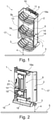
- eine Frontansicht einer erfindungsgemäßen Fahrzeugtreppe oder Maschinentreppe in schematischer Darstellung;
- Fig. 2:
- die in
Fig. 1 dargestellte Fahrzeugtreppe in einer Rückansicht; - Fig. 3:
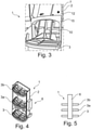
- einen Ausschnitt einer weiteren Ausführung der erfindungsgemäßen Fahrzeugtreppe in einer Frontansicht;
- Fig. 4:
- eine schematische Darstellung einer weiteren Ausführungsform einer Fahrzeugtreppe;
- Fig. 5:
- eine schematische Darstellung einer weiteren Ausführungsform einer Fahrzeugtreppe.
- Eine erfindungsgemäße Fahrzeugtreppe 1 oder Maschinentreppe ist in schematischer Darstellung in
Figur 1 gezeigt. Die inFigur 1 gezeigte Fahrzeugtreppe 1 befindet sich in einer Ruhestellung. - Die Fahrzeugtreppe 1 umfasst einen Träger 2 sowie Trittelemente 3, 3a, 3b. Vorliegend sind Trittelemente 3a, 3b innerhalb des Trägers 2 angeordnet. In vorliegender Ausführung ist ein Trittelement 3 außerhalb des Trägers 2 angeordnet. Das Trittelement 3 kann als unterstes Trittelement aufgefasst werden und ist über eine Baugruppe 6 (siehe auch
Figur 2 ) mit dem Träger 2 verbunden. Auf diese Weise kann das Trittelement 3 bei Einwirken einer Gewichtskraft in Richtung eines Untergrunds 5 bewegt werden. Somit ist bei Einwirken einer Gewichtskraft auf das Trittelement 3 ein Abstand 4 zwischen dem Trittelement 3 und dem Untergrund 5 verringerbar. Bei der Bewegung zur Verringerung des Abstands wirkt das dynamische Bremsmittel 7 bremsend, wodurch ein besonders körperschonender Ausstieg von einem Fahrzeug ermöglicht wird. - Der Träger 2 umfasst Befestigungsmittel 18, 18a, mittels denen die Fahrzeugtreppe 1 in hier nicht näher dargestellter Art und Weise mit einem Fahrzeug, beispielsweise einer Landmaschine, etc. verbindbar ist.
- Es ist in der
Figur 1 dargestellt, dass der Träger 2 zur Einstellung einer Geschwindigkeit der Bewegung eines Trittelements 3 eine Baugruppe 6 umfasst, die ein dynamisches Bremsmittel 7 umfasst. Dadurch wird ein besonders körperschonendes Absteigen von der Fahrzeugtreppe 1 bzw. von einem Fahrzeug ermöglicht. Im Ausführungsbeispiel ist das dynamische Bremsmittel als Wirbelstrombremse ausgebildet. - Ferner ist ersichtlich, dass die Fahrzeugtreppe 1 ein mit dem Träger 2 und der Baugruppe 6 verbundenes Rückstellelement 11 umfasst. Vorliegend ist das Rückstellelement 11 als Gasdruckfeder ausgebildet.
- Bei Verlassen eines Fahrzeugs über die Fahrzeugtreppe 1 erfolgt durch Betreten des Trittelements 3 eine Einwirkung einer Gewichtskraft auf dieses Trittelement 3. Infolge der oben beschriebenen Freigabe bzw. Entriegelung ist das Trittelement 3 derart höhenverschiebbar, dass ein Abstand 4 zu einem Untergrund verringerbar ist.
- Bei einem Einstieg in ein Fahrzeug ausgehend von einer Ruhestellung der Fahrzeugtreppe 1 wird bei Betreten eines Trittelementes 3a, welches als Betätigungsmittel 9 ausgestaltet ist, ein weiteres Trittelement 3, das vorliegend ein unterstes Trittelement darstellt, entriegelt. Ein derartiges Entriegeln kann auch als freigeben aufgefasst werden. Ohne weitere Einwirkung einer Gewichtskraft bleibt das Trittelement 3 in dieser dargestellten Ruhestellung, d.h. ohne Änderungen des Abstands 4 zu einem Untergrund 5.
- Das Trittelement 3a ist kippbar um eine Lagerachse 13 in dem Träger 2 angeordnet. Hierzu umfasst der Träger 2 ein Langloch 14, in welchem das Trittelement 3a z.B. mittels eines Bolzens haltbar bzw. bewegbar ist.
- Das Trittelement 3a kann als Bedienelement der Rastklinke 20 wirken, die in ein Rastelement einrastbar bzw. ausrastbar ist.
- Auf diese Weise kann die Fahrzeugtreppe z.B. mittels des Führungsmittels in zwei Rastpositionen bewegt werden, wobei diese als eine erste Rastposition und als eine zweite Rastposition aufgefasst werden können. Eine erste Rastposition liegt z.B. beim Absteigen der Treppe vor, eine zweite Position beim Aufsteigen der Treppe.
- Die Verringerung des Abstands 4 zum Untergrund 5 kann auch als Abgleiten des Trittelements 3 aufgefasst werden. Dieses Gleiten wird durch kontinuierliche Bremswirkung des dynamischen Bremsmittels 7 ermöglicht. Somit kann ein Benutzer der Fahrzeugtreppe 1 bei Betreten des gleitenden Trittelements 3 besonders körperschonend aus bzw. von einem Fahrzeug aussteigen bzw. absteigen. Besonders vorteilhaft ist zudem, dass ein Abstieg von einem Fahrzeug in einer Vorwärtsbewegung erfolgen kann, wodurch der Abstieg auch besonders zügig erfolgen kann.
- Im gezeigten Ausführungsbeispiel ist die Baugruppe 6 an einer Rückseite 16 des Trägers 2 angeordnet.
- In der
Figur 2 ist auch dargestellt, dass die Fahrzeugtreppe 1 ein Rückstellmittel 8 umfasst, welches vorliegend als Federmittel ausgebildet ist. Das Rückstellmittel 8 ist mit dem Träger 2 und der Baugruppe 6 verbunden. Im gezeigten Ausführungsbeispiel ist das Rückstellmittel 8 mit einer Rastklinke 20 verbunden. - In der
Figur 3 ist eine Ausführungsform einer erfindungsgemäßen Fahrzeugtreppe 1 gezeigt, die sich in einem ausgefahrenen Zustand befindet, der vorliegt, wenn ein Abstand eines Trittelements 3 zu einem Untergrund (siehe auchFigur 1 ) verringert wurde. Es ist ausFigur 3 ersichtlich, dass die Fahrzeugtreppe 1 einen Zwischentritt 15 umfasst. Der Zwischentritt 15 ist oberhalb des Trittelements 3 angeordnet. - Der Zwischentritt 15 ist unterhalb eines weiteren Trittelements (siehe z.B.
Figur 1 ) angeordnet. Somit ist der Zwischentritt 15 zwischen zwei Trittelementen angeordnet und ermöglicht einen vereinfachten Aufstieg der Fahrzeugtreppe 1. Im Ausführungsbeispiel umfasst der Zwischentritt 15 eine Profilierung 12, die einen verbesserten Halt eines Benutzers beim Betreten des Zwischentritts 15 ermöglicht. - Im Ausführungsbeispiel ist der Zwischentritt 15 L-förmig ausgebildet und zwischen zwei Trittelementen angeordnet. Ein solcher Zwischentritt ist besonders einfach nachrüstbar.
- In der
Figur 5 ist dargestellt, dass die Baugruppe 6 seitlich an dem Träger 2 angeordnet ist. Dies ist insbesondere dann vorteilhaft, wenn ein Bauraum am Fahrzeug eine rückseitige Baugruppenanordnung nicht erlaubt. In der Figur 6 ist gezeigt, dass die Baugruppe 6 an einer Vorderseite 17 des Trägers 2 zentriert durch Unterbrechung einer Fläche Trittelementen 3, 3a, 3b angeordnet ist. -
- 1
- Fahrzeugtreppe
- 2
- Träger
- 3
- Trittelement
- 3a
- Trittelement
- 3b
- Trittelement
- 4
- Abstand
- 5
- Untergrund
- 6
- Baugruppe
- 7
- Dynamisches Bremsmittel
- 8
- Rückstellmittel
- 9
- Betätigungsmittel
- 10
- Führungsmittel
- 11
- Rückstellelement
- 12
- Profilierung
- 13
- Lagerachse
- 14
- Langloch
- 15
- Zusatztritt
- 16
- Rückseite
- 17
- Vorderseite
- 18
- Befestigungsmittel
- 18a
- Befestigungsmittel
- 19
- Zahnrad
- 20
- Rastklinke
Claims (12)
- Fahrzeugtreppe (1) oder Maschinentreppe, umfassend einen Träger (2) sowie Trittelemente (3, 3a, 3b), wobei bei Einwirken einer Gewichtskraft auf ein Trittelement (3, 3a, 3b) ein Abstand (4) mindestens eines Trittelements zu einem Untergrund (5) verringerbar ist, wobei der Träger (2) zur Einstellung einer Geschwindigkeit der Bewegung des mindestens einen Trittelements (3, 3a, 3b) zumindest eine Baugruppe (6) umfasst, welche Baugruppe (6) wenigstens ein dynamisches Bremsmittel (7) umfasst,wobeiwenigstens ein als Zusatztritt (15) ausgebildetes weiteres Trittelement bei einer Vergrößerung des Abstands (4) mitbewegbar istdadurch gekennzeichnet, dass ein Führungsmittel (10) vorgesehen ist, wobei zumindest ein Trittelement (3, 3a, 3b) mittels des Führungsmittels (10) an dem Träger (2) höhenverschiebbar befestigbar ist,wobei ein Abstand (4) mindestens eines Trittelements (3, 3a, 3b) zu einem Untergrund (5) durch Vergrößerung eines Abstands (10) zwischen zwei Trittelementen (3, 3a, 3b) verringerbar ist.
- Fahrzeugtreppe oder Maschinentreppe nach Anspruch 1, dadurch gekennzeichnet, dass die Fahrzeugtreppe (1) zumindest ein mit dem Träger (2) und der Baugruppe (6) verbundenes Rückstellelement (11) umfasst.
- Fahrzeugtreppe oder Maschinentreppe nach einem der vorangehenden Ansprüche, dadurch gekennzeichnet, dass das dynamische Bremsmittel (7) in seiner Bremswirkung manuell oder automatisch einstellbar, insbesondere in seiner Bremskraft manuell oder automatisch justierbar ist.
- Fahrzeugtreppe oder Maschinentreppe nach einem der vorangehenden Ansprüche, dadurch gekennzeichnet, dass zur Verringerung des Abstands (4) zumindest ein Betätigungsmittel (9) vorgesehen ist, welches zumindest als Verriegelungsmittel und/oder zumindest als Entriegelungsmittel ausgebildet ist und vorzugsweise als Trittelement (3, 3a, 3b) ausgebildet ist.
- Fahrzeugtreppe oder Maschinentreppe nach einem der vorangehenden Ansprüche, dadurch gekennzeichnet, dass das dynamische Bremsmittel (7) als Wirbelstrombremse ausgebildet ist.
- Fahrzeugtreppe oder Maschinentreppe nach einem der vorangehenden Ansprüche, dadurch gekennzeichnet, dass das dynamische Bremsmittel (7) als pneumatisch wirkende Bremse oder als hydraulisch wirkende Bremse oder als mechanisch wirkende Bremse, insbesondere Reibbremse ausgebildet ist.
- Fahrzeugtreppe oder Maschinentreppe nach einem der vorangehenden Ansprüche, dadurch gekennzeichnet, dass die Baugruppe (6) zumindest ein Führungsmittel (10) umfasst, welches vorzugsweise eine Zahnstange oder eine Spindel oder einen Seilzug umfasst.
- Fahrzeugtreppe oder Maschinentreppe nach einem der vorangehenden Ansprüche, dadurch gekennzeichnet, dass die Baugruppe (6) wenigstens ein Rastelement umfasst, welches Rastelement vorzugsweise wenigstens eine erste Rastposition und wenigstens eine zweite Rastposition umfasst.
- Fahrzeugtreppe oder Maschinentreppe nach einem der vorangehenden Ansprüche, dadurch gekennzeichnet, dass die Baugruppe (6) den Träger (2) umfasst und/oder dass die Baugruppe (6) wenigstens eine Rastklinke (20) und ein damit verbindbares Rückstellmittel (8) umfasst, wobei die Rastklinke (20) vorzugsweise in ein Rastelement einrastbar und ausrastbar ist.
- Fahrzeugtreppe oder Maschinentreppe nach Anspruch 7, dadurch gekennzeichnet, das Führungsmittel (10) vorzugsweise zwei Haltemittel umfasst, wobei ein Trittelement (3, 3a, 3b) in einer ersten Stellung in einem ersten Haltemittel haltbar, insbesondere rastbar ist und nach einer Vergrößerung des Abstands (4) benachbarter Trittelemente (3, 3a, 3b) in einer zweiten Stellung in einem zweiten Haltemittel haltbar, insbesondere rastbar ist.
- Fahrzeugtreppe oder Maschinentreppe nach einem der vorangehenden Ansprüche, dadurch gekennzeichnet, dass die Baugruppe (6) an einer Rückseite (16) des Trägers (2) angeordnet ist oder dass die Baugruppe (6) an einer Vorderseite (17) des Trägers (2) vorzugsweise zentriert durch Unterbrechung einer Fläche wenigstens eines Trittelements (3, 3a, 3b) angeordnet ist.
- Fahrzeugtreppe oder Maschinentreppe nach einem der vorangehenden Ansprüche, dadurch gekennzeichnet, dass wenigstens ein Trittelement (3, 3a, 3b) mittels der Baugruppe (6) mit dem Träger (2) verbindbar ist.
Applications Claiming Priority (2)
| Application Number | Priority Date | Filing Date | Title |
|---|---|---|---|
| DE102017107444.9A DE102017107444A1 (de) | 2017-04-06 | 2017-04-06 | Fahrzeugtreppe oder Maschinentreppe |
| EP18166033.3A EP3385123B1 (de) | 2017-04-06 | 2018-04-06 | Fahrzeugtreppe oder maschinentreppe |
Related Parent Applications (1)
| Application Number | Title | Priority Date | Filing Date |
|---|---|---|---|
| EP18166033.3A Division EP3385123B1 (de) | 2017-04-06 | 2018-04-06 | Fahrzeugtreppe oder maschinentreppe |
Publications (2)
| Publication Number | Publication Date |
|---|---|
| EP3736405A1 EP3736405A1 (de) | 2020-11-11 |
| EP3736405B1 true EP3736405B1 (de) | 2022-03-02 |
Family
ID=61912993
Family Applications (2)
| Application Number | Title | Priority Date | Filing Date |
|---|---|---|---|
| EP18166033.3A Not-in-force EP3385123B1 (de) | 2017-04-06 | 2018-04-06 | Fahrzeugtreppe oder maschinentreppe |
| EP20183599.8A Not-in-force EP3736405B1 (de) | 2017-04-06 | 2018-04-06 | Fahrzeugtreppe oder maschinentreppe |
Family Applications Before (1)
| Application Number | Title | Priority Date | Filing Date |
|---|---|---|---|
| EP18166033.3A Not-in-force EP3385123B1 (de) | 2017-04-06 | 2018-04-06 | Fahrzeugtreppe oder maschinentreppe |
Country Status (2)
| Country | Link |
|---|---|
| EP (2) | EP3385123B1 (de) |
| DE (1) | DE102017107444A1 (de) |
Families Citing this family (3)
| Publication number | Priority date | Publication date | Assignee | Title |
|---|---|---|---|---|
| CN111071158A (zh) * | 2019-12-19 | 2020-04-28 | 勇猛机械股份有限公司 | 一种用于收获机上的可折叠式上车梯 |
| CN114919501A (zh) * | 2022-06-06 | 2022-08-19 | 一汽解放汽车有限公司 | 翻转踏板及车辆 |
| DE102024121060A1 (de) * | 2024-07-24 | 2026-01-29 | Liebherr-Werk Nenzing Gmbh | Aufstiegsleiter für eine Arbeitsmaschine, insbesondere für einen fahrbaren Kran |
Family Cites Families (6)
| Publication number | Priority date | Publication date | Assignee | Title |
|---|---|---|---|---|
| US3033309A (en) | 1959-11-06 | 1962-05-08 | Fugere Dale | Retractible stepladder for vehicles |
| US4145066A (en) | 1977-10-11 | 1979-03-20 | Shearin Nadeane P | Emergency exit step for school bus |
| US4982974A (en) * | 1989-02-03 | 1991-01-08 | Interco Tire Corporation | Adjustable high vehicle boarding step |
| US5064022A (en) * | 1989-05-30 | 1991-11-12 | Marrowbone Development Company | Ladder apparatus and method for large mobile equipment |
| US5697626A (en) | 1995-05-16 | 1997-12-16 | Mcdaniel Manufacturing, Inc. | Extendable vehicle running board |
| DE102017106369A1 (de) * | 2016-03-24 | 2017-09-28 | Daniel Griener | Fahrzeug- oder Industrieleiter bzw. -treppe |
-
2017
- 2017-04-06 DE DE102017107444.9A patent/DE102017107444A1/de not_active Withdrawn
-
2018
- 2018-04-06 EP EP18166033.3A patent/EP3385123B1/de not_active Not-in-force
- 2018-04-06 EP EP20183599.8A patent/EP3736405B1/de not_active Not-in-force
Also Published As
| Publication number | Publication date |
|---|---|
| DE102017107444A1 (de) | 2018-10-11 |
| EP3385123B1 (de) | 2020-07-15 |
| EP3385123A1 (de) | 2018-10-10 |
| EP3736405A1 (de) | 2020-11-11 |
Similar Documents
| Publication | Publication Date | Title |
|---|---|---|
| EP3478533B1 (de) | Längseinsteller sowie fahrzeugsitz | |
| EP3736405B1 (de) | Fahrzeugtreppe oder maschinentreppe | |
| EP1316465A1 (de) | Arretiervorrichtung mit gerillten Sperrstiften | |
| DE102010029129A1 (de) | Verstellvorrichtung für Kraftfahrzeugsitze, insbesondere Höhenverstellvorrichtungen | |
| DE102012104987B4 (de) | Außentritt für den Führerstand von Schienenfahrzeugen | |
| DE69715773T2 (de) | Verschiebbare Sicherheitsvorrichtung | |
| DE3920124A1 (de) | Sitz-gleitschienenanordnung | |
| DE2011422A1 (de) | Vorrichtung zum gemeinsamen Verstellen der Pedale von Kraftfahrzeugen in Fahrzeug längsnchtung | |
| EP3974281B1 (de) | Zustiegeinrichtung für ein fahrzeug | |
| EP3670254B1 (de) | Fahrzeugsitz mit verstellfunktion | |
| DE19981927C1 (de) | Seilzug-Fensterheber für Fahrzeuge | |
| DE10104077A1 (de) | Verstellmechanismus für eine Armlehne einer Kraftfahrzeugtür | |
| DE102016114884B4 (de) | Kraftfahrzeuginnenraumanordnung mit einer Betätigungseinrichtung für ein Arretiersystem sowie Arretiersystem | |
| DE202007006910U1 (de) | Sitzhöhenverstelleinrichtung sowie Kraftfahrzeugsitz | |
| DE102017106369A1 (de) | Fahrzeug- oder Industrieleiter bzw. -treppe | |
| DE3742389C2 (de) | Fernbetätigbare Höhenverstellvorrichtung | |
| EP1145924A2 (de) | Vorrichtung zur Gurthöhenverstellung an Sicherheitsgurten | |
| EP3366509B1 (de) | Schienenanordnung für einen längseinsteller und fahrzeugsitz | |
| DE10228465A1 (de) | Kraftfahrzeug | |
| EP4450357B1 (de) | Teleskopierbares führungssystem für schiebetritte | |
| DE102015221079A1 (de) | Längseinsteller für einen fahrzeugsitz, fahrzeugsitz | |
| DE202019104035U1 (de) | Aufhängevorrichtung für ein Flugzeugfahrwerk | |
| DE102019201184A1 (de) | Fahrkorb für eine Aufzugsanlage mit Linearmotorantrieb, Aufzugsanlage mit einem solchen Fahrkorb und Verfahren zum Betreiben einer Aufzugsanlage | |
| DE3236656A1 (de) | Anordnung an einem personenverkehrsmittel, insbesondere omnibus, zum aufnehmen bzw. abgeben von rollstuhlfahrgaesten | |
| EP3347626A1 (de) | Parksperrenvorrichtung für ein kraftfahrzeuggetriebe |
Legal Events
| Date | Code | Title | Description |
|---|---|---|---|
| PUAI | Public reference made under article 153(3) epc to a published international application that has entered the european phase |
Free format text: ORIGINAL CODE: 0009012 |
|
| STAA | Information on the status of an ep patent application or granted ep patent |
Free format text: STATUS: THE APPLICATION HAS BEEN PUBLISHED |
|
| AC | Divisional application: reference to earlier application |
Ref document number: 3385123 Country of ref document: EP Kind code of ref document: P |
|
| AK | Designated contracting states |
Kind code of ref document: A1 Designated state(s): AL AT BE BG CH CY CZ DE DK EE ES FI FR GB GR HR HU IE IS IT LI LT LU LV MC MK MT NL NO PL PT RO RS SE SI SK SM TR |
|
| STAA | Information on the status of an ep patent application or granted ep patent |
Free format text: STATUS: REQUEST FOR EXAMINATION WAS MADE |
|
| 17P | Request for examination filed |
Effective date: 20210511 |
|
| RBV | Designated contracting states (corrected) |
Designated state(s): AL AT BE BG CH CY CZ DE DK EE ES FI FR GB GR HR HU IE IS IT LI LT LU LV MC MK MT NL NO PL PT RO RS SE SI SK SM TR |
|
| GRAP | Despatch of communication of intention to grant a patent |
Free format text: ORIGINAL CODE: EPIDOSNIGR1 |
|
| STAA | Information on the status of an ep patent application or granted ep patent |
Free format text: STATUS: GRANT OF PATENT IS INTENDED |
|
| INTG | Intention to grant announced |
Effective date: 20210929 |
|
| GRAS | Grant fee paid |
Free format text: ORIGINAL CODE: EPIDOSNIGR3 |
|
| GRAA | (expected) grant |
Free format text: ORIGINAL CODE: 0009210 |
|
| STAA | Information on the status of an ep patent application or granted ep patent |
Free format text: STATUS: THE PATENT HAS BEEN GRANTED |
|
| AC | Divisional application: reference to earlier application |
Ref document number: 3385123 Country of ref document: EP Kind code of ref document: P |
|
| AK | Designated contracting states |
Kind code of ref document: B1 Designated state(s): AL AT BE BG CH CY CZ DE DK EE ES FI FR GB GR HR HU IE IS IT LI LT LU LV MC MK MT NL NO PL PT RO RS SE SI SK SM TR |
|
| REG | Reference to a national code |
Ref country code: GB Ref legal event code: FG4D Free format text: NOT ENGLISH |
|
| REG | Reference to a national code |
Ref country code: CH Ref legal event code: EP Ref country code: AT Ref legal event code: REF Ref document number: 1472360 Country of ref document: AT Kind code of ref document: T Effective date: 20220315 |
|
| REG | Reference to a national code |
Ref country code: DE Ref legal event code: R096 Ref document number: 502018008972 Country of ref document: DE |
|
| REG | Reference to a national code |
Ref country code: IE Ref legal event code: FG4D Free format text: LANGUAGE OF EP DOCUMENT: GERMAN |
|
| REG | Reference to a national code |
Ref country code: LT Ref legal event code: MG9D |
|
| REG | Reference to a national code |
Ref country code: NL Ref legal event code: MP Effective date: 20220302 |
|
| PG25 | Lapsed in a contracting state [announced via postgrant information from national office to epo] |
Ref country code: SE Free format text: LAPSE BECAUSE OF FAILURE TO SUBMIT A TRANSLATION OF THE DESCRIPTION OR TO PAY THE FEE WITHIN THE PRESCRIBED TIME-LIMIT Effective date: 20220302 Ref country code: RS Free format text: LAPSE BECAUSE OF FAILURE TO SUBMIT A TRANSLATION OF THE DESCRIPTION OR TO PAY THE FEE WITHIN THE PRESCRIBED TIME-LIMIT Effective date: 20220302 Ref country code: NO Free format text: LAPSE BECAUSE OF FAILURE TO SUBMIT A TRANSLATION OF THE DESCRIPTION OR TO PAY THE FEE WITHIN THE PRESCRIBED TIME-LIMIT Effective date: 20220602 Ref country code: LT Free format text: LAPSE BECAUSE OF FAILURE TO SUBMIT A TRANSLATION OF THE DESCRIPTION OR TO PAY THE FEE WITHIN THE PRESCRIBED TIME-LIMIT Effective date: 20220302 Ref country code: HR Free format text: LAPSE BECAUSE OF FAILURE TO SUBMIT A TRANSLATION OF THE DESCRIPTION OR TO PAY THE FEE WITHIN THE PRESCRIBED TIME-LIMIT Effective date: 20220302 Ref country code: ES Free format text: LAPSE BECAUSE OF FAILURE TO SUBMIT A TRANSLATION OF THE DESCRIPTION OR TO PAY THE FEE WITHIN THE PRESCRIBED TIME-LIMIT Effective date: 20220302 Ref country code: BG Free format text: LAPSE BECAUSE OF FAILURE TO SUBMIT A TRANSLATION OF THE DESCRIPTION OR TO PAY THE FEE WITHIN THE PRESCRIBED TIME-LIMIT Effective date: 20220602 |
|
| PG25 | Lapsed in a contracting state [announced via postgrant information from national office to epo] |
Ref country code: PL Free format text: LAPSE BECAUSE OF FAILURE TO SUBMIT A TRANSLATION OF THE DESCRIPTION OR TO PAY THE FEE WITHIN THE PRESCRIBED TIME-LIMIT Effective date: 20220302 Ref country code: LV Free format text: LAPSE BECAUSE OF FAILURE TO SUBMIT A TRANSLATION OF THE DESCRIPTION OR TO PAY THE FEE WITHIN THE PRESCRIBED TIME-LIMIT Effective date: 20220302 Ref country code: GR Free format text: LAPSE BECAUSE OF FAILURE TO SUBMIT A TRANSLATION OF THE DESCRIPTION OR TO PAY THE FEE WITHIN THE PRESCRIBED TIME-LIMIT Effective date: 20220603 Ref country code: FI Free format text: LAPSE BECAUSE OF FAILURE TO SUBMIT A TRANSLATION OF THE DESCRIPTION OR TO PAY THE FEE WITHIN THE PRESCRIBED TIME-LIMIT Effective date: 20220302 |
|
| PG25 | Lapsed in a contracting state [announced via postgrant information from national office to epo] |
Ref country code: NL Free format text: LAPSE BECAUSE OF FAILURE TO SUBMIT A TRANSLATION OF THE DESCRIPTION OR TO PAY THE FEE WITHIN THE PRESCRIBED TIME-LIMIT Effective date: 20220302 |
|
| PG25 | Lapsed in a contracting state [announced via postgrant information from national office to epo] |
Ref country code: SM Free format text: LAPSE BECAUSE OF FAILURE TO SUBMIT A TRANSLATION OF THE DESCRIPTION OR TO PAY THE FEE WITHIN THE PRESCRIBED TIME-LIMIT Effective date: 20220302 Ref country code: SK Free format text: LAPSE BECAUSE OF FAILURE TO SUBMIT A TRANSLATION OF THE DESCRIPTION OR TO PAY THE FEE WITHIN THE PRESCRIBED TIME-LIMIT Effective date: 20220302 Ref country code: RO Free format text: LAPSE BECAUSE OF FAILURE TO SUBMIT A TRANSLATION OF THE DESCRIPTION OR TO PAY THE FEE WITHIN THE PRESCRIBED TIME-LIMIT Effective date: 20220302 Ref country code: PT Free format text: LAPSE BECAUSE OF FAILURE TO SUBMIT A TRANSLATION OF THE DESCRIPTION OR TO PAY THE FEE WITHIN THE PRESCRIBED TIME-LIMIT Effective date: 20220704 Ref country code: EE Free format text: LAPSE BECAUSE OF FAILURE TO SUBMIT A TRANSLATION OF THE DESCRIPTION OR TO PAY THE FEE WITHIN THE PRESCRIBED TIME-LIMIT Effective date: 20220302 Ref country code: CZ Free format text: LAPSE BECAUSE OF FAILURE TO SUBMIT A TRANSLATION OF THE DESCRIPTION OR TO PAY THE FEE WITHIN THE PRESCRIBED TIME-LIMIT Effective date: 20220302 |
|
| PG25 | Lapsed in a contracting state [announced via postgrant information from national office to epo] |
Ref country code: IS Free format text: LAPSE BECAUSE OF FAILURE TO SUBMIT A TRANSLATION OF THE DESCRIPTION OR TO PAY THE FEE WITHIN THE PRESCRIBED TIME-LIMIT Effective date: 20220702 Ref country code: AL Free format text: LAPSE BECAUSE OF FAILURE TO SUBMIT A TRANSLATION OF THE DESCRIPTION OR TO PAY THE FEE WITHIN THE PRESCRIBED TIME-LIMIT Effective date: 20220302 |
|
| REG | Reference to a national code |
Ref country code: CH Ref legal event code: PL |
|
| REG | Reference to a national code |
Ref country code: DE Ref legal event code: R097 Ref document number: 502018008972 Country of ref document: DE |
|
| REG | Reference to a national code |
Ref country code: BE Ref legal event code: MM Effective date: 20220430 |
|
| PLBE | No opposition filed within time limit |
Free format text: ORIGINAL CODE: 0009261 |
|
| STAA | Information on the status of an ep patent application or granted ep patent |
Free format text: STATUS: NO OPPOSITION FILED WITHIN TIME LIMIT |
|
| PG25 | Lapsed in a contracting state [announced via postgrant information from national office to epo] |
Ref country code: MC Free format text: LAPSE BECAUSE OF FAILURE TO SUBMIT A TRANSLATION OF THE DESCRIPTION OR TO PAY THE FEE WITHIN THE PRESCRIBED TIME-LIMIT Effective date: 20220302 Ref country code: LU Free format text: LAPSE BECAUSE OF NON-PAYMENT OF DUE FEES Effective date: 20220406 Ref country code: LI Free format text: LAPSE BECAUSE OF NON-PAYMENT OF DUE FEES Effective date: 20220430 Ref country code: DK Free format text: LAPSE BECAUSE OF FAILURE TO SUBMIT A TRANSLATION OF THE DESCRIPTION OR TO PAY THE FEE WITHIN THE PRESCRIBED TIME-LIMIT Effective date: 20220302 Ref country code: CH Free format text: LAPSE BECAUSE OF NON-PAYMENT OF DUE FEES Effective date: 20220430 |
|
| 26N | No opposition filed |
Effective date: 20221205 |
|
| PG25 | Lapsed in a contracting state [announced via postgrant information from national office to epo] |
Ref country code: SI Free format text: LAPSE BECAUSE OF FAILURE TO SUBMIT A TRANSLATION OF THE DESCRIPTION OR TO PAY THE FEE WITHIN THE PRESCRIBED TIME-LIMIT Effective date: 20220302 Ref country code: BE Free format text: LAPSE BECAUSE OF NON-PAYMENT OF DUE FEES Effective date: 20220430 |
|
| GBPC | Gb: european patent ceased through non-payment of renewal fee |
Effective date: 20220602 |
|
| PG25 | Lapsed in a contracting state [announced via postgrant information from national office to epo] |
Ref country code: IE Free format text: LAPSE BECAUSE OF NON-PAYMENT OF DUE FEES Effective date: 20220406 |
|
| PG25 | Lapsed in a contracting state [announced via postgrant information from national office to epo] |
Ref country code: GB Free format text: LAPSE BECAUSE OF NON-PAYMENT OF DUE FEES Effective date: 20220602 |
|
| PG25 | Lapsed in a contracting state [announced via postgrant information from national office to epo] |
Ref country code: IT Free format text: LAPSE BECAUSE OF FAILURE TO SUBMIT A TRANSLATION OF THE DESCRIPTION OR TO PAY THE FEE WITHIN THE PRESCRIBED TIME-LIMIT Effective date: 20220302 |
|
| PGFP | Annual fee paid to national office [announced via postgrant information from national office to epo] |
Ref country code: FR Payment date: 20230417 Year of fee payment: 6 Ref country code: DE Payment date: 20230418 Year of fee payment: 6 |
|
| PG25 | Lapsed in a contracting state [announced via postgrant information from national office to epo] |
Ref country code: MK Free format text: LAPSE BECAUSE OF FAILURE TO SUBMIT A TRANSLATION OF THE DESCRIPTION OR TO PAY THE FEE WITHIN THE PRESCRIBED TIME-LIMIT Effective date: 20220302 Ref country code: CY Free format text: LAPSE BECAUSE OF FAILURE TO SUBMIT A TRANSLATION OF THE DESCRIPTION OR TO PAY THE FEE WITHIN THE PRESCRIBED TIME-LIMIT Effective date: 20220302 |
|
| PG25 | Lapsed in a contracting state [announced via postgrant information from national office to epo] |
Ref country code: HU Free format text: LAPSE BECAUSE OF FAILURE TO SUBMIT A TRANSLATION OF THE DESCRIPTION OR TO PAY THE FEE WITHIN THE PRESCRIBED TIME-LIMIT; INVALID AB INITIO Effective date: 20180406 |
|
| REG | Reference to a national code |
Ref country code: AT Ref legal event code: MM01 Ref document number: 1472360 Country of ref document: AT Kind code of ref document: T Effective date: 20230406 |
|
| PG25 | Lapsed in a contracting state [announced via postgrant information from national office to epo] |
Ref country code: TR Free format text: LAPSE BECAUSE OF FAILURE TO SUBMIT A TRANSLATION OF THE DESCRIPTION OR TO PAY THE FEE WITHIN THE PRESCRIBED TIME-LIMIT Effective date: 20220302 |
|
| PG25 | Lapsed in a contracting state [announced via postgrant information from national office to epo] |
Ref country code: AT Free format text: LAPSE BECAUSE OF NON-PAYMENT OF DUE FEES Effective date: 20230406 |
|
| PG25 | Lapsed in a contracting state [announced via postgrant information from national office to epo] |
Ref country code: AT Free format text: LAPSE BECAUSE OF NON-PAYMENT OF DUE FEES Effective date: 20230406 |
|
| PG25 | Lapsed in a contracting state [announced via postgrant information from national office to epo] |
Ref country code: MT Free format text: LAPSE BECAUSE OF FAILURE TO SUBMIT A TRANSLATION OF THE DESCRIPTION OR TO PAY THE FEE WITHIN THE PRESCRIBED TIME-LIMIT Effective date: 20220302 |
|
| REG | Reference to a national code |
Ref country code: DE Ref legal event code: R119 Ref document number: 502018008972 Country of ref document: DE |
|
| PG25 | Lapsed in a contracting state [announced via postgrant information from national office to epo] |
Ref country code: DE Free format text: LAPSE BECAUSE OF NON-PAYMENT OF DUE FEES Effective date: 20241105 |
|
| PG25 | Lapsed in a contracting state [announced via postgrant information from national office to epo] |
Ref country code: FR Free format text: LAPSE BECAUSE OF NON-PAYMENT OF DUE FEES Effective date: 20240430 |
|
| PG25 | Lapsed in a contracting state [announced via postgrant information from national office to epo] |
Ref country code: FR Free format text: LAPSE BECAUSE OF NON-PAYMENT OF DUE FEES Effective date: 20240430 Ref country code: DE Free format text: LAPSE BECAUSE OF NON-PAYMENT OF DUE FEES Effective date: 20241105 |
|
| PGFP | Annual fee paid to national office [announced via postgrant information from national office to epo] |
Ref country code: AT Payment date: 20260410 Year of fee payment: 5 |