EP3736373A1 - Vorrichtung zum entwässern von wäsche - Google Patents
Vorrichtung zum entwässern von wäsche Download PDFInfo
- Publication number
- EP3736373A1 EP3736373A1 EP20173316.9A EP20173316A EP3736373A1 EP 3736373 A1 EP3736373 A1 EP 3736373A1 EP 20173316 A EP20173316 A EP 20173316A EP 3736373 A1 EP3736373 A1 EP 3736373A1
- Authority
- EP
- European Patent Office
- Prior art keywords
- membrane
- fastening ring
- press
- collar
- plate
- Prior art date
- Legal status (The legal status is an assumption and is not a legal conclusion. Google has not performed a legal analysis and makes no representation as to the accuracy of the status listed.)
- Granted
Links
Images
Classifications
-
- D—TEXTILES; PAPER
- D06—TREATMENT OF TEXTILES OR THE LIKE; LAUNDERING; FLEXIBLE MATERIALS NOT OTHERWISE PROVIDED FOR
- D06F—LAUNDERING, DRYING, IRONING, PRESSING OR FOLDING TEXTILE ARTICLES
- D06F47/00—Apparatus of the press type for expelling water from the linen
- D06F47/06—Apparatus of the press type for expelling water from the linen by a flexible diaphragm
-
- B—PERFORMING OPERATIONS; TRANSPORTING
- B30—PRESSES
- B30B—PRESSES IN GENERAL
- B30B9/00—Presses specially adapted for particular purposes
- B30B9/02—Presses specially adapted for particular purposes for squeezing-out liquid from liquid-containing material, e.g. juice from fruits, oil from oil-containing material
- B30B9/04—Presses specially adapted for particular purposes for squeezing-out liquid from liquid-containing material, e.g. juice from fruits, oil from oil-containing material using press rams
- B30B9/06—Presses specially adapted for particular purposes for squeezing-out liquid from liquid-containing material, e.g. juice from fruits, oil from oil-containing material using press rams co-operating with permeable casings or strainers
-
- B—PERFORMING OPERATIONS; TRANSPORTING
- B30—PRESSES
- B30B—PRESSES IN GENERAL
- B30B9/00—Presses specially adapted for particular purposes
- B30B9/02—Presses specially adapted for particular purposes for squeezing-out liquid from liquid-containing material, e.g. juice from fruits, oil from oil-containing material
- B30B9/22—Presses specially adapted for particular purposes for squeezing-out liquid from liquid-containing material, e.g. juice from fruits, oil from oil-containing material using a flexible member, e.g. diaphragm, urged by fluid pressure
-
- D—TEXTILES; PAPER
- D06—TREATMENT OF TEXTILES OR THE LIKE; LAUNDERING; FLEXIBLE MATERIALS NOT OTHERWISE PROVIDED FOR
- D06F—LAUNDERING, DRYING, IRONING, PRESSING OR FOLDING TEXTILE ARTICLES
- D06F47/00—Apparatus of the press type for expelling water from the linen
- D06F47/04—Apparatus of the press type for expelling water from the linen by a fluid-actuated ram
Definitions
- the invention relates to a device for dewatering laundry according to the preamble of claim 1.
- Devices of the type discussed here are used to largely remove liquids from washed laundry. Such devices can also serve to rinse washed laundry. Such devices are preferably used in commercial laundries for dewatering all types of laundry.
- Known devices have a press ram which can be moved up and down by a hydraulic cylinder and which has a ram plate and a press membrane fastened below it.
- the press membrane can be elastically deformed and a fluid can be applied from the inside.
- the washed laundry coming from a washing machine arrives in a press basket of the device arranged under the press ram.
- the ram When the ram is lowered by the hydraulic cylinder, it compresses the laundry in the press basket.
- the laundry in the press basket is dewatered and, if necessary, rinsed beforehand.
- the disadvantage of the known devices for dewatering laundry is the fastening of the press membrane under the die plate of the press ram.
- the invention is based on the object of creating a device for dewatering laundry which enables the press membrane to be simply, accurately positioned and reliably fastened under the ram plate of the press ram.
- a device for solving the problem has the features of claim 1. It is provided that a fastening ring for connecting the press membrane to the die plate is designed in such a way that an at least positive connection of the fastening ring with the press membrane, in particular its membrane collar, is achieved. This connection is permanent and can be produced precisely in that the fastening ring allows and ensures a dimensionally accurate, above all exactly centric connection of the press membrane with the die plate. This dimensional accuracy also ensures that the pressing force from the press membrane is introduced uniformly, above all symmetrically, into the punch plate and that no transverse forces are transmitted to the hydraulic cylinder during pressing.
- the positive connection of the fastening ring with the membrane collar of the press membrane is made by at least partially embedding the fastening ring with at least one undercut in the membrane collar.
- the at least one undercut leads to a form-fitting embedding of the fastening ring in the membrane collar and allows the form-fitting connection of the fastening ring to the membrane collar to be brought about in a simple manner together with embedding the fastening ring in the membrane collar.
- the cross section of the fastening ring tapers towards its upper end face, which rests below the stamp plate. This tapering creates at least one undercut. This leads to the undercut connection of the fastening ring in the membrane collar of the press membrane.
- the tapering of the cross section of the fastening ring in the direction of its end face resting on the end plate is preferably brought about by at least one annular surface of the fastening ring that runs obliquely and / or inclined.
- This at least one inclined or inclined ring surface of the fastening ring leads to at least one undercut that brings about the positive connection of the fastening ring with the membrane collar.
- At least the inclined, inclined, profiled, toothed and / or stepped annular surface of the fastening ring is preferably completely embedded in the membrane collar.
- This configuration contributes in particular to the secure, heavy-duty and permanent connection, in particular a form-fitting connection, of the fastening ring with the membrane collar.
- the inner and outer ring surfaces of the fastening ring are designed in such a way that both ring surfaces contribute to the production of the undercut and / or form-fitting connection of the fastening ring with the membrane collar of the press membrane.
- the outer, larger, annular surface of the fastening ring is preferably designed in such a way that it contributes to the undercut and / or form-fitting connection of the fastening ring to the membrane collar.
- the membrane surface and / or the membrane collars of the press membrane preferably the entire press membrane, to be formed from an elastic and / or flexible, in particular rubber-like material. This allows the press membrane to cling flexibly to the laundry to be dewatered.
- the membrane collar and also the membrane surface are made of an elastic and / or flexible, in particular rubber-like, material, the fastening ring formed in the manner described above contributes to the particularly secure, stable and permanent connection of the stamp plate to the flexible membrane collar.
- the stamp plate and / or the fastening ring are formed from a dimensionally stable, preferably metallic, material.
- the fastening ring formed from such a stable material is used for the permanently stable connection and fastening of the press membrane, which is flexible except for the fastening ring, with the stamp plate.
- the fastening ring is connected to the membrane collar by gluing and / or vulcanizing.
- the connection of the fastening ring to the membrane collar which is already reliable due to the form fit, is reinforced by the additional gluing and / or vulcanization of the fastening ring to the membrane collar of the press membrane.
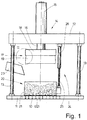
- the device shown in the figures is a so-called dewatering press for dewatering, in particular, washed laundry 10 of any kind.
- the device squeezes out the liquid contained in the washed laundry, in particular the so-called bound liquor, as far as possible.
- the device shown can additionally also serve to rinse the laundry 10 before dewatering.
- the device has a frame with a partially liquid-permeable base plate 11, which is optionally assigned a storage tank for collecting the liquid squeezed out of the laundry 10, a press yoke 12 arranged at a distance above the base plate 11 and several, for example four, between the base plate 11 and The press yoke 12 provided upright columns 13 for rigid, spaced connection of the base plate 11 with the press yoke 12.
- a hydraulic cylinder 14 In the middle (based on the base area) of the press yoke 12 is a hydraulic cylinder 14.
- a cylinder body 15 of the hydraulic cylinder 14 is fixed above the press yoke 12 connected to the same.
- a retractable and extendable piston rod 16 of the hydraulic cylinder 14 protrudes downward relative to the press yoke 12.
- a lower end of the piston rod 16 of the hydraulic cylinder 14 is fixedly connected to a ram 17 of the device.
- the press ram 17 has a rigid ram plate 18 fixedly connected to the lower end of the piston rod 16 of the hydraulic cylinder 14 and a press membrane 19 made of an elastically deformable material and fastened below it.
- the Fig. 1 shows the ram 17 in its raised starting position, in which the piston rod 16 has moved into the cylinder body 15 of the hydraulic cylinder 14.
- a press basket 20 is arranged below the press ram 17.
- the press basket 20 is completely open on the top and bottom side, in that it only consists of a circumferential basket shell 21.
- the press basket 20 rests with its open underside on the base plate 11, preferably at least on that area of the base plate 11 which is liquid-permeable, for example by means of a grid of through-holes 22.
- the press basket 20 is connected laterally to a smaller hydraulic cylinder 24, namely the lower end of its piston rod 25.
- a cylinder body 26 of the small hydraulic cylinder 24 is firmly connected to the underside of the press yoke 12.
- the press basket 20 can be raised in order to transport a laundry cake of the dehydrated laundry 10 from the base plate 11.
- a corresponding conveyor for example a liquid-permeable upper run of a belt conveyor, can be attached to the top of the base plate 11. be assigned.
- the press basket 20 then rests on the liquid-permeable upper run of such a belt conveyor when the laundry 10 is dewatered.
- the small hydraulic cylinder 24 moves the empty press basket 20 down again onto the base plate 11 or onto the upper run of the belt conveyor assigned to the base plate 11.
- the press ram 17, specifically both the ram plate 18 and the press membrane 19 thereof, and the press basket 20 are of cylindrical design.
- the diameters of the press ram 17, in particular the press membrane 19, and the press basket 20 are selected so that the press membrane 19 can dip into the same through the open top of the press basket 20 and thereby compress the laundry 10 in the press basket 20 as well as rinse and / or dehydrate it.
- the inside diameter of the basket shell 21 corresponds approximately to the largest outer diameter of the press membrane 19.
- the inner diameter of the press basket 20 and / or its basket shell 21 is somewhat larger than the maximum outer diameter of the press membrane 19.
- the press membrane 19 is hat-shaped in vertical cross section.
- the press membrane 19 has a lower, circular membrane surface 27 and a membrane collar 28 which adjoins the membrane surface 27 and is cylindrical.
- the underside of the membrane collar 28 is integrally formed on the membrane surface 27 and surrounds it on the outside.
- the press membrane 19 is made entirely of an elastically deformable material, such as rubber or the like.
- the membrane collar 28 is detachably connected to the underside of the rigid, dimensionally stable stamp plate 18 made of a metallic material.
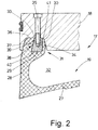
- the connection shown in detail is made by means of a dimensionally stable, rigid fastening ring 29, which, like the stamp plate 18, is preferably made of a metallic material.
- the underside of the plunger plate 18 is provided with an annular circumferential groove 30, which corresponds to an upper region 31, in particular an end region, of the membrane collar 28 of the press membrane 19, so that this upper region 31 of the membrane collar 28 adjoins the groove 30 open at the bottom the underside of the stamp plate 18 at least largely fills.
- a cavity 32 closed off from the underside of the die plate 18 is created inside the press membrane 19.
- This cavity 32 is filled with a fluid, in particular a liquid, fillable, preferably completely.
- the elastic deformability of the press membrane 19 it forms a flexible press cushion under the stamp plate 18, whereby the membrane surface 27 of the press membrane 19 in particular clings flexibly to the laundry 10 that can be compressed for dewatering in the press basket 20.
- connection of the upper region 31 of the membrane collar 28 of the press membrane 19 is fluid-tight, in particular liquid-tight, to which the special fastening of the press membrane 19 under the stamp plate 18, described in more detail below, also contributes.
- the pressing membrane 19 is fastened under the stamp plate 18 by screwing the fastening ring 29 to the stamp plate 18.
- the fastening ring 29 has blind bores 34 extending from its end face 33 resting under the stamp plate 18 Fastening ring 29 distributed.
- a lower threaded section of a screw 35 extending from above through the punch plate 18 is screwed into each blind hole 34 in the fastening ring 29.
- the fastening ring 29 is firmly screwed with its end face 33 against an annular bottom surface 36 of the groove 30 in the circular underside of the punch plate 18, preferably with all screws 35 pretensioned.
- the fastening ring 29 is not only screwed to the stamp plate 18 by several screws 35; it is also firmly and permanently connected to the membrane collar 28, in particular its upper annular region 31. This connection is positive.
- the fastening ring 29 is embedded with a form fit in the upper region 31 of the membrane collar 28, at least for the most part. This embedding takes place in such a way that an outer circumference of the upper region 31 of the membrane collar 28 with an annular end face 37 ends flush with the upper end face 33 of the fastening ring 29 and thus also rests against the bottom surface 36 of the groove 30 on the underside of the stamp plate 18, and although preferably sealing.
- the form-fitting connection of the fastening ring 29 to the upper region 31 of the membrane collar 28 takes place in that the cross section of the fastening ring 29 decreases towards its end face 33 which is screwed tightly under the stamp plate 18. This creates an undercut in the upper region 31 of the membrane collar 28 on the outer jacket surface, formed by an outer surface 38 of the fastening ring 29. In the region of this undercut, the form-fitting connection of the fastening ring 29 with the membrane collar 28 of the press membrane 19 is established.
- the outer surface 38 of the fastening ring 29, which is used for the form-fitting and / or undercut embedding of at least part of the fastening ring 29 in the upper region 31 of the membrane collar 28, is designed to run obliquely and / or inclined towards the upper end face 33 of the fastening ring 29.
- the outer surface 38 of the fastening ring 29 is profiled. Is preferred as shown in the Fig. 2 the profiling of the outer surface 38 of the fastening ring 29 is formed by a stepped and / or toothed profiling of the outer surface 38. This gradation takes place through steps 39 following one another along the outer surface 38. In the exemplary embodiment shown, the outer surface 38 has five steps 39.
- the number of steps 39 can be larger or smaller. As a result of the gradation of the outer surface 38 of the fastening ring 29, the sloping or inclined course of the outer surface 38 of the fastening ring 29 also comes about.
- the steps 39 are formed equally at right angles and / or the same size. Starting from a lower end face 40 of the fastening ring 29, the steps 39 follow one another in such a way that the width of the fastening ring 29 continuously decreases towards the upper end face 33 and thereby the width of the fastening ring 29 gradually decreases towards its upper end face 33.
- Each of the preferably identically formed steps 39 has a length (in the vertical direction) which is greater than the width (in the horizontal direction).
- the length of each step 39 can be about 4 to 5 times the width.
- the upper and / or lower step 39 is longer than the intermediate steps 39.
- the upper and / or lower steps 39 can be about 5 to 7 times as long as their width.
- fastening ring 29 An alternative exemplary embodiment of the fastening ring 29 is conceivable in which its outer surface 38 is smooth and only has a sloping and / or inclined profile.
- the course of the inclination or the bevel is such that the width of the fastening ring 29 decreases continuously towards its upper end face 33.
- the outer surface 38 of the fastening ring 29 is given a frustoconical shape with a diameter that decreases towards the end face 33.
- the undercut for the form-fitting connection, in particular embedding, of the fastening ring 29 in the upper region 31 of the membrane collar 28 comes about.
- fastening ring 29 is conceivable in which the frustoconical outer surface 38 is provided with a toothing or with a grooving, in particular a thread-like grooving.
Landscapes
- Engineering & Computer Science (AREA)
- Mechanical Engineering (AREA)
- Textile Engineering (AREA)
- Accessory Of Washing/Drying Machine, Commercial Washing/Drying Machine, Other Washing/Drying Machine (AREA)
Abstract
Description
- Die Erfindung betrifft eine Vorrichtung zum Entwässern von Wäsche gemäß dem Oberbegriff des Anspruchs 1.
- Vorrichtungen der hier angesprochenen Art dienen dazu, Flüssigkeiten aus gewaschener Wäsche weitestgehend zu entfernen. Solche Vorrichtungen können auch zusätzlich dazu dienen, gewaschene Wäsche zu spülen. Bevorzugt finden solche Vorrichtungen in gewerblichen Wäschereien zum Entwässern von Wäsche aller Art Verwendung.
- Bekannte Vorrichtungen verfügen über einen von einem Hydraulikzylinder auf- und abbewegbaren Pressstempel, der über eine Stempelplatte und eine darunter befestigte Pressmembran verfügt. Die Pressmembran ist elastisch verformbar und von innen mit einem Fluid beaufschlagbar. Die aus einer Waschmaschine kommende gewaschene Wäsche gelangt in einen unter dem Pressstempel angeordneten Presskorb der Vorrichtung. Durch vom Hydraulikzylinder erfolgten Herunterfahren des Pressstempels drückt dieser die Wäsche im Presskorb zusammen. Dabei wird die Wäsche im Presskorb entwässert und gegebenenfalls zuvor gespült.
- Nachteilig an den bekannten Vorrichtungen zum Entwässern von Wäsche ist die Befestigung der Pressmembran unter der Stempelplatte des Pressstempels.
- Der Erfindung liegt die Aufgabe zugrunde, eine Vorrichtung zum Entwässern von Wäsche zu schaffen, die eine einfache, positionsgenaue und zuverlässige Befestigung der Pressmembran unter der Stempelplatte des Pressstempels ermöglicht.
- Eine Vorrichtung zur Lösung der Aufgabe weist die Merkmale des Anspruchs 1 auf. Dabei ist es vorgesehen, einen Befestigungsring zur Verbindung der Pressmembran mit der Stempelplatte so auszubilden, dass eine mindestens formschlüssige Verbindung des Befestigungsrings mit der Pressmembran, insbesondere ihrem Membrankragen, zustande kommt. Diese Verbindung ist dauerhaft und lässt sich exakt herstellen, indem der Befestigungsring ein maßhaltiges, vor allem exakt zentrisches Verbinden der Pressmembran mit der Stempelplatte zulässt und gewährleistet. Diese Maßhaltigkeit sorgt auch dafür, dass die Presskraft von der Pressmembran gleichmäßig, vor allem symmetrisch, in die Stempelplatte eingeleitet wird und dadurch beim Pressen keine Querkräfte auf den Hydraulikzylinder übertragen werden.
- Bei einer besonders vorteilhaften Ausgestaltung der Vorrichtung ist es vorgesehen, die formschlüssige Verbindung des Befestigungsrings mit dem Membrankragen der Pressmembran durch eine mindestens teilweise Einbettung des Befestigungsrings mit wenigstens einer Hinterschneidung im Membrankragen vorzunehmen. Die mindestens eine Hinterschneidung führt zu einer formschlüssigen Einbettung des Befestigungsrings im Membrankragen und lässt die formschlüssige Verbindung des Befestigungsrings mit dem Membrankragen auf einfache Weise zusammen mit Einbettung des Befestigungsrings im Membrankragen herbeiführen.
- Bevorzugt ist es vorgesehen, dass sich der Querschnitt des Befestigungsrings zu seiner unter der Stempelplatte anliegenden, oberen Stirnfläche hin verjüngt. Durch diese Verjüngung entsteht wenigstens eine Hinterschneidung. Das führt zur hinterschnittenen Verbindung des Befestigungsrings im Membrankragen der Pressmembran.
- Bevorzugt wird die Verjüngung des Querschnitts des Befestigungsrings in Richtung zu seiner an der Stirnplatte anliegenden Stirnfläche durch mindestens eine schräg und/oder geneigt verlaufende Ringfläche des Befestigungsrings herbeigeführt. Diese mindestens eine schräge oder geneigte Ringfläche des Befestigungsrings führt zu mindestens einer Hinterschneidung, die die formschlüssige Verbindung des Befestigungsrings mit dem Membrankragen herbeiführt.
- Eine vorteilhafte alternative oder zusätzliche Bildung der Verjüngung des Querschnitts des Befestigungsrings in Richtung zu seiner an der Stempelplatte anliegenden Stirnfläche kann durch eine profilierte, vorzugsweise gezahnte und/oder abgestufte Ringfläche des Befestigungsrings erfolgen. Das führt zu einer Mehrzahl aufeinanderfolgender Hinterschneidungen und einem hochwirksamen Formschluss zur präzisen, dauerhaft festen Verbindung des Befestigungsrings mit dem Membrankragen.
- Gemäß einer vorteilhaften Weiterbildungsmöglichkeit der Vorrichtung ist mindestens die schräge, geneigte, profilierte, gezahnte und/oder abgestufte Ringfläche des Befestigungsrings vorzugsweise vollständig im Membrankragen eingebettet. Diese Ausgestaltung trägt besonders zur sicheren, hochbelastbaren und dauerhaften Verbindung, insbesondere formschlüssigen Verbindung, des Befestigungsrings mit dem Membrankragen bei.
- Es ist denkbar, dass die innere und äußere Ringfläche des Befestigungsrings solchermaßen ausgebildet sind, dass beide Ringflächen zur Herstellung der hinterschnittenen und/oder formschlüssigen Verbindung des Befestigungsrings mit dem Membrankragen der Pressmembran beitragen. Es kann aber auch ausreichend sein, dass nur eine Ringfläche zur Bildung der formschlüssigen Verbindung des Befestigungsrings mit dem Membrankragen beiträgt. In diesem Falle wird bevorzugt die äußere, flächenmäßig größere, Ringfläche des Befestigungsrings so ausgebildet, dass sie zur hinterschnittenen und/oder formschlüssigen Verbindung des Befestigungsrings mit dem Membrankragen beiträgt.
- Es ist bevorzugt vorgesehen, die Membranfläche und/oder die Membrankragen der Pressmembran, vorzugsweise die gesamte Pressmembran, aus einem elastischen und/ oder flexiblen, insbesondere gummiartigen Material zu bilden. Dadurch kann sich die Pressmembran flexibel an die zu entwässernde Wäsche anschmiegen. Vor allem dann, wenn der Membrankragen und auch die Membranfläche aus einem elastischen und/oder flexiblen, insbesondere gummiartigen, Material gebildet sind, trägt der in vorstehend beschriebener Weise ausgebildete Befestigungsring zur besonders sicheren, stabilen und dauerhaften Verbindung der Stempelplatte mit dem flexiblen Membrankragen bei.
- Die Stempelplatte und/oder der Befestigungsring sind aus einem formstabilen, vorzugsweise metallischen, Material gebildet. Vor allem der aus einem solchen stabilen Material gebildete Befestigungsring dient zur dauerhaft haltbaren stabilen Verbindung und Befestigung der bis auf den Befestigungsring flexiblen Pressmembran mit der Stempelplatte bei.
- Es ist denkbar, dass der Befestigungsring zusätzlich zur formschlüssigen Verbindung mit dem Membrankragen durch Kleben und/oder Vulkanisieren mit dem Membrankragen verbunden ist. Die schon aufgrund des Formschlusses zuverlässige Verbindung des Befestigungsrings mit dem Membrankragen wird noch verstärkt durch das zusätzliche Verkleben und/oder Vulkanisieren des Befestigungsrings mit dem Membrankragen der Pressmembran.
- Ein bevorzugtes Ausführungsbeispiel der Erfindung wird nachfolgend anhand der Zeichnung näher erläutert. In dieser zeigen:
- Fig. 1
- eine schematische Seitenansicht einer Vorrichtung zum Entwässern von Wäsche, und
- Fig. 2
- eine vergrößerte Einzelheit II aus der
Fig. 1 im Schnitt. - Bei der in den Figuren gezeigten Vorrichtung handelt es sich um eine sogenannte Entwässerungspresse zum Entwässern von insbesondere gewaschener Wäsche 10 jeglicher Art. Dabei wird von der Vorrichtung die in der gewaschenen Wäsche enthaltene Flüssigkeit, insbesondere die sogenannte gebundene Flotte, weitestgehend herausgepresst. Die gezeigte Vorrichtung kann zusätzlich auch dazu dienen, die Wäsche 10 vor dem Entwässern zu spülen.
- Die Vorrichtung verfügt über ein Gestell mit einer teilweise flüssigkeitsdurchlässigen Sockelplatte 11, der gegebenenfalls ein Speichertank zum Auffangen der aus der Wäsche 10 ausgepressten Flüssigkeit zugeordnet ist, ein mit Abstand über der Sockelplatte 11 angeordnetes Pressenjoch 12 und mehrere, beispielsweise vier, zwischen der Sockelplatte 11 und dem Pressenjoch 12 vorgesehene aufrechte Säulen 13 zur starren, beabstandeten Verbindung der Sockelplatte 11 mit dem Pressenjoch 12. In der Mitte (bezogen auf die Grundfläche) des Pressenjochs 12 befindet sich ein Hydraulikzylinder 14. Ein Zylinderkörper 15 des Hydraulikzylinders 14 ist oberhalb des Pressenjochs 12 fest mit demselben verbunden. Eine ein- und ausfahrbare Kolbenstange 16 des Hydraulikzylinders 14 ragt gegenüber dem Pressenjoch 12 nach unten vor. Ein unteres Ende der Kolbenstange 16 des Hydraulikzylinders 14 ist fest mit einem Pressstempel 17 der Vorrichtung verbunden. Der Pressstempel 17 verfügt über eine fest mit dem unteren Ende der Kolbenstange 16 des Hydraulikzylinders 14 verbundene, starre Stempelplatte 18 und eine darunter befestigte Pressmembran 19 aus einem elastisch verformbaren Material. Die
Fig. 1 zeigt den Pressstempel 17 in seiner hochgefahrenen Ausgangsstellung, in der die Kolbenstange 16 in den Zylinderkörper 15 des Hydraulikzylinders 14 eingefahren ist. - Unterhalb des Pressstempels 17 ist ein Presskorb 20 angeordnet. Der Presskorb 20 ist an der Ober- und Unterseite vollständig offen, indem er lediglich aus einem umlaufenden Korbmantel 21 besteht. Zum Beladen und Entwässern ruht der Presskorb 20 mit seiner offenen Unterseite auf der Sockelplatte 11, und zwar vorzugsweise mindestens auf demjenigen Bereich der Sockelplatte 11, der beispielsweise mittels eines Rasters von Durchgangsbohrungen 22 flüssigkeitsdurchlässig ist.
- Bei der in der
Fig. 1 gezeigten Ausgangsstellung der Vorrichtung mit hochgefahrenem Pressstempel 17 und eingefahrener Kolbenstange 16 befindet sich zwischen der Unterseite der Pressmembran 19 und der offenen Oberseite des Presskorbs 20 ein Zwischenraum. Dieser dient zur Beladung des Presskorbs 20 mit zu entwässernder und/oder zu spülender Wäsche 10. Die Beladung erfolgt auf einem mittels einer andeutungsweise in derFig. 1 gezeigten Beladerutsche 23. - Bei der dargestellten Vorrichtung ist der Presskorb 20 seitlich mit einem kleineren Hydraulikzylinder 24 verbunden, und zwar dem unteren Ende seiner Kolbenstange 25. Ein Zylinderkörper 26 des kleinen Hydraulikzylinders 24 ist fest mit der Unterseite des Pressenjochs 12 verbunden. Durch den kleinen Hydraulikzylinder 24 kann nach dem Entwässern der Wäsche 10 der Presskorb 20 hochgefahren werden zum Abtransport eines Wäschekuchens der entwässerten Wäsche 10 von der Sockelplatte 11. Zu diesem Zweck kann der Oberseite der Sockelplatte 11 ein entsprechender Förderer, beispielsweise ein flüssigkeitsdurchlässiges Obertrum eines Gurtförderers, zugeordnet sein. Dann ruht der Presskorb 20 beim Entwässern der Wäsche 10 auf dem flüssigkeitsdurchlässigen Obertrum eines solchen Gurtförderers. Nach dem Abtransport des Wäschekuchens von der Sockelplatte 11 wird vom kleinen Hydraulikzylinder 24 der leere Presskorb 20 wieder heruntergefahren auf die Sockelplatte 11 bzw. auf das Obertrum des der Sockelplatte 11 zugeordneten Gurtförderers.
- Bei der gezeigten Vorrichtung sind der Pressstempel 17, und zwar sowohl die Stempelplatte 18 als auch die Pressmembran 19 desselben, als auch der Presskorb 20 zylindrisch ausgebildet. Die Durchmesser des Pressstempels 17, insbesondere der Pressmembran 19, und des Presskorbs 20 sind so gewählt, dass die Pressmembran 19 durch die offene Oberseite des Presskorbs 20 in denselben eintauchen und dabei die Wäsche 10 im Presskorb 20 zusammendrücken sowie spülen und/oder entwässern kann. Der Innendurchmesser des Korbmantels 21 entspricht dabei etwa dem größten Außendurchmesser der Pressmembran 19. Insbesondere ist der Innendurchmesser des Presskorbs 20 und/oder seines Korbmantels 21 etwas größer als der maximale Außendurchmesser der Pressmembran 19.
- Die Pressmembran 19 ist im vertikalen Querschnitt hutartig ausgebildet. Dazu verfügt die Pressmembran 19 über eine untere, kreisförmige Membranfläche 27 und einen oberhalb der Membranfläche 27 an dieselbe sich anschließenden Membrankragen 28, der zylindrisch ausgebildet ist. Die Unterseite des Membrankragens 28 ist einstückig an die Membranfläche 27 angeformt und umgibt diese außenseitig. Die Pressmembran 19 ist vollständig aus einem elastisch verformbaren Material, wie zum Beispiel Gummi oder ähnlichem gebildet.
- Mit einem oberen Rand ist der Membrankragen 28 lösbar mit der Unterseite der starren, formstabilen Stempelplatte 18 aus einem metallischen Material verbunden. Diese in der
Fig. 2 detailliert gezeigte Verbindung erfolgt mittels eines formstabilen, starren Befestigungsrings 29, der vorzugsweise wie auch die Stempelplatte 18 aus einem metallischen Material hergestellt ist. - Beim in der
Fig. 2 gezeigten Pressstempel 17 ist die Unterseite der Stempelplatte 18 mit einer ringförmig umlaufenden Nut 30 versehen, die mit einem oberen Bereich 31, insbesondere Endbereich, des Membrankragens 28 der Pressmembran 19 korrespondiert, so dass dieser obere Bereich 31 des Membrankragens 28 die unten offene Nut 30 an der Unterseite der Stempelplatte 18 mindestens größtenteils ausfüllt. - Infolge der hutartigen Ausbildung der Pressmembran 19 und der Verbindung des oberen Bereichs 31 des Membrankragens 28 der Pressmembran 19 mit der Stempelplatte 18 entsteht im Inneren der Pressmembran 19 ein von der Unterseite der Stempelplatte 18 abgeschlossener Hohlraum 32. Dieser Hohlraum 32 ist mit einem Fluid, insbesondere einer Flüssigkeit, ausfüllbar, und zwar vorzugsweise vollständig. Infolge der elastischen Verformbarkeit der Pressmembran 19 bildet diese unter der Stempelplatte 18 ein flexibles Presspolster, wodurch vor allem die Membranfläche 27 der Pressmembran 19 sich oben an die zum Entwässern im Presskorb 20 zusammenpressbare Wäsche 10 flexibel anschmiegt. Damit hierbei das Fluid, insbesondere die Flüssigkeit, im Hohlraum 32 der Pressmembran 19 nicht aus derselben entweichen kann, ist die Verbindung des oberen Bereichs 31 des Membrankragens 28 der Pressmembran 19 fluiddicht, insbesondere flüssigkeitsdicht, ausgebildet, wozu auch die nachfolgend näher beschriebene besondere Befestigung der Pressmembran 19 unter der Stempelplatte 18 beiträgt.
- Die Befestigung der Pressmembran 19 unter der Stempelplatte 18 erfolgt durch Verschrauben des Befestigungsrings 29 mit der Stempelplatte 18. Dazu verfügt der Befestigungsring 29 von seiner unter der Stempelplatte 18 anliegenden Stirnfläche 33 ausgehende Sackbohrungen 34. Mehrere gleiche Sackbohrungen 34 sind gleichmäßig über die kreisringartige Stirnfläche 33 des Befestigungsrings 29 verteilt. In jede Sackbohrung 34 im Befestigungsring 29 ist ein unterer Gewindeabschnitt einer sich von oben durch die Stempelplatte 18 erstreckenden Schraube 35 eingedreht. Nach dem Festziehen der jeweiligen Schraube 35 ist der Befestigungsring 29 mit seiner Stirnfläche 33 fest gegen eine ringförmige Bodenfläche 36 der Nut 30 in der kreisförmigen Unterseite der Stempelplatte 18 geschraubt, vorzugsweise unter Vorspannung aller Schrauben 35.
- Der Befestigungsring 29 ist nicht nur mit der Stempelplatte 18 durch mehrere Schrauben 35 verschraubt; er ist auch fest und dauerhaft mit dem Membrankragen 28, insbesondere seinem oberen ringförmigen Bereich 31, verbunden. Diese Verbindung erfolgt formschlüssig. Dazu ist der Befestigungsring 29 mit Formschluss im oberen Bereich 31 des Membrankragens 28 eingebettet, und zwar mindestens größtenteils. Diese Einbettung geschieht derart, dass ein äußerer Umfang des oberen Bereichs 31 des Membrankragens 28 mit einer ringförmigen Stirnfläche 37 bündig mit der oberen Stirnfläche 33 des Befestigungsrings 29 abschließt und dadurch auch an der Bodenfläche 36 der Nut 30 an der Unterseite der Stempelplatte 18 anliegt, und zwar vorzugsweise dichtend.
- Die formschlüssige Verbindung des Befestigungsrings 29 mit dem oberen Bereich 31 des Membrankragens 28 erfolgt dadurch, dass der Querschnitt des Befestigungsrings 29 zu seiner unter der Stempelplatte 18 anliegenden und festgeschraubten Stirnfläche 33 hin abnimmt. Dadurch entsteht an der äußeren Mantelfläche, gebildet von einer Außenfläche 38 des Befestigungsrings 29, eine Hinterschneidung im oberen Bereich 31 des Membrankragens 28. Im Bereich dieser Hinterschneidung kommt die formschlüssige Verbindung des Befestigungsrings 29 mit dem Membrankragen 28 der Pressmembran 19 zustande.
- Die zur formschlüssigen und/oder hinterschnittenen Einbettung mindestens eines Teils des Befestigungsrings 29 im oberen Bereich 31 des Membrankragens 28 dienende Außenfläche 38 des Befestigungsrings 29 ist zur oberen Stirnfläche 33 des Befestigungsrings 29 hin schräg und/oder geneigt verlaufend ausgebildet. Im gezeigten Ausführungsbeispiel (
Fig. 2 ) ist die Außenfläche 38 des Befestigungsrings 29 profiliert. Bevorzugt ist gemäß der Darstellung in derFig. 2 die Profilierung der Außenfläche 38 des Befestigungsrings 29 durch eine gestufte und/oder gezahnte Profilierung der Außenfläche 38 gebildet. Diese Abstufung erfolgt durch entlang der Außenfläche 38 aufeinanderfolgende Stufen 39. Im gezeigten Ausführungsbeispiel weist die Außenfläche 38 fünf Stufen 39 auf. Hierauf ist die Erfindung aber nicht beschränkt. Die Anzahl der Stufen 39 kann größer oder auch kleiner sein. Infolge der Abstufung der Außenfläche 38 des Befestigungsrings 29 kommt auch der schräge bzw. geneigte Verlauf der Außenfläche 38 des Befestigungsrings 29 zustande. - Beim Ausführungsbeispiel der
Fig. 2 sind die Stufen 39 gleichermaßen rechtwinklig und/ oder gleich groß ausgebildet. Ausgehend von einer unteren Stirnfläche 40 des Befestigungsrings 29 folgen die Stufen 39 derart aufeinander, dass die Breite des Befestigungsrings 29 zur oberen Stirnfläche 33 hin kontinuierlich abnimmt und sich dadurch die Breite des Befestigungsrings 29 zu seiner oberen Stirnfläche 33 hin nach und nach gestuft verringert. Jede der vorzugsweise gleich ausgebildete Stufen 39 verfügt über eine Länge (in vertikaler Richtung), die größer ist als die Breite (in horizontaler Richtung). Beispielsweise kann die Länge jeder Stufe 39 etwa das 4- bis 5-fache der Breite betragen. Denkbar ist es schließlich auch, dass die obere und/oder untere Stufe 39 länger ist als die dazwischenliegenden Stufen 39. Beispielsweise können die oberen und/oder unteren Stufen 39 etwa 5-fach bis 7-fach so lang sein wie ihre Breite. - Es kann vorgesehen sein, den Befestigungsring 29 nicht nur formschlüssig mindestens größtenteils im oberen Bereich 31 des Membrankragens 28 einzubetten, sondern ihn zusätzlich auch noch im oberen Bereich 31 des Membrankragens 28 zu verkleben und/ oder einzuvulkanisieren.
- Es ist ein alternatives Ausführungsbeispiel des Befestigungsrings 29 denkbar, bei dem seine Außenfläche 38 glatt und nur mit einer schrägem und/oder geneigten Verlauf versehen ist. Der Verlauf der Neigung oder der Abschrägung ist derart, dass sich die Breite des Befestigungsrings 29 zu seiner oberen Stirnfläche 33 hin kontinuierlich verringert. Dadurch erhält die Außenfläche 38 des Befestigungsrings 29 eine kegelstumpfartige Gestalt mit zur Stirnfläche 33 abnehmendem Durchmesser. Auf diese Weise kommt die Hinterschneidung zur formschlüssigen Verbindung, insbesondere Einbettung, des Befestigungsrings 29 im oberen Bereich 31 des Membrankragens 28 zustande.
- Es sind weitere Ausführungsbeispiele des Befestigungsrings 29 denkbar, bei denen die kegelstumpfartige Außenfläche 38 mit einer Verzahnung oder mit einer Rillung, insbesondere einer gewindeartigen Rillung, versehen ist.
- Schließlich ist es auch denkbar, nicht nur die Außenfläche 38 des Befestigungsrings 29 konisch, profiliert und/oder abgestuft auszubilden, sondern auch eine im gezeigten Ausführungsbeispiel (
Fig. 2 ) zylindrische Innenfläche 41 des Befestigungsrings 29 oder nur die Innenfläche 41. Denkbar wäre es dann, die Innenfläche 41 mit einer Neigung zu versehen, so dass diese zur Verringerung der Breite des Befestigungsrings 29 zu seiner Stirnfläche 33 hin beiträgt und auch eine Hinterschneidung zur formschlüssigen Verbindung des Befestigungsrings 29 mit dem oberen Bereich 31 des Membrankragens 28 bildet. -
- 10
- Wäsche
- 11
- Sockelplatte
- 12
- Pressenjoch
- 13
- Säule
- 14
- Hydraulikzylinder
- 15
- Zylinderkörper
- 16
- Kolbenstange
- 17
- Pressstempel
- 18
- Stempelplatte
- 19
- Pressmembran
- 20
- Presskorb
- 21
- Korbmantel
- 22
- Durchgangsbohrung
- 23
- Beladerutsche
- 24
- kleiner Hydraulikzylinder
- 25
- Kolbenstange
- 26
- Zylinderkörper
- 27
- Membranfläche
- 28
- Membrankragen
- 29
- Befestigungsring
- 30
- Nut
- 31
- oberer Bereich (von 28)
- 32
- Hohlraum
- 33
- Stirnfläche
- 34
- Sackbohrung
- 35
- Schraube
- 36
- Bodenfläche
- 37
- Stirnfläche
- 38
- Außenfläche
- 39
- Stufe
- 40
- untere Stirnfläche
- 41
- Innenfläche
Claims (10)
- Vorrichtung zum Entwässern von Wäsche (10), mit einem von einem Hydraulikzylinder (14) auf- und abbewegbaren Pressstempel (17), der eine Stempelplatte (18) mit einer darunter befestigbaren Pressmembran (19) aufweist, die über eine Membranfläche (27) und einen daran angeformten Membrankragen (28) verfügt, wobei der Membrankragen (28) mit einem Befestigungsring (29) zum Verbinden der Pressmembran (19) mit der Stempelplatte (18) des Pressstempels (17) versehen ist, dadurch gekennzeichnet, dass der Befestigungsring (29) mindestens formschlüssig mit dem Membrankragen (28) verbunden ist.
- Vorrichtung nach Anspruch 1, dadurch gekennzeichnet, dass die formschlüssige Verbindung des Befestigungsrings (29) mit dem Membrankragen (28) der Pressmembran (19) durch eine mindestens teilweise Einbettung des Befestigungsrings (29) mit vorzugsweise wenigstens einer Hinterschneidung im Membrankragen (28) erfolgt.
- Vorrichtung nach Anspruch 1 oder 2, dadurch gekennzeichnet, dass der Querschnitt des Befestigungsrings (29) sich zu seiner unter der Stempelplatte (18) anliegenden Stirnfläche (33) hin verjüngt zur Bildung mindestens einer Hinterschneidung des Befestigungsrings (29) im Membrankragen (28) der Pressmembran (19).
- Vorrichtung nach einem der vorhergehenden Ansprüche, dadurch gekennzeichnet, dass die Verjüngung des Querschnitts des Befestigungsrings (29) zu seiner an der Stempelplatte (18) anliegenden Stirnfläche (33) durch mindestens eine schräg und/oder geneigt verlaufende Ringfläche des Befestigungsrings (29) erfolgt.
- Vorrichtung nach mindestens einem der Ansprüche 1 bis 3???, dadurch gekennzeichnet, dass die Verjüngung des Querschnitts des Befestigungsrings (29) zu seiner an der Stempelplatte (18) anliegenden Stirnfläche (33) durch mindestens eine profilierte, vorzugsweise gezahnte und/oder abgestufte, Ringfläche des Befestigungsrings (29) erfolgt.
- Vorrichtung nach einem der vorhergehenden Ansprüche, dadurch gekennzeichnet, dass mindestens die schräge, geneigte, profilierte, gezahnte und/oder abgestufte Ringfläche des Befestigungsrings (29) vollständig im Membrankragen (28) eingebettet ist.
- Vorrichtung nach einem der vorhergehenden Ansprüche, dadurch gekennzeichnet, dass die eine Außenfläche (38) des Befestigungsrings (29) bildende äußere Ringfläche des Befestigungsrings (29) schräg, geneigt, profiliert, gezahnt und/oder abgestuft ist.
- Vorrichtung nach einem der vorhergehenden Ansprüche, dadurch gekennzeichnet, dass mindestens die Membranfläche (27) der Pressmembran (19), vorzugsweise auch der Membrankragen (28), aus einem elastischen und/oder flexiblen, insbesondere gummiartigen, Material gebildet ist bzw. sind.
- Vorrichtung nach einem der vorherigen Ansprüche, dadurch gekennzeichnet, dass mindestens die Stempelplatte (18) und der Befestigungsring (29) aus einem stabilen, metallischen Material gebildet sind.
- Vorrichtung nach einem der vorhergehenden Ansprüche, dadurch gekennzeichnet, dass der Befestigungsring (29) zusätzlich zur formschlüssigen Verbindung mit dem Membrankragen (28) durch Kleben und/oder Vulkanisieren mit dem Membrankragen (28) der Pressmembran (19) verbunden ist.
Applications Claiming Priority (1)
| Application Number | Priority Date | Filing Date | Title |
|---|---|---|---|
| DE202019002021.7U DE202019002021U1 (de) | 2019-05-08 | 2019-05-08 | Vorrichtung zum Entwässern von Wäsche |
Publications (2)
| Publication Number | Publication Date |
|---|---|
| EP3736373A1 true EP3736373A1 (de) | 2020-11-11 |
| EP3736373B1 EP3736373B1 (de) | 2021-09-08 |
Family
ID=67623081
Family Applications (1)
| Application Number | Title | Priority Date | Filing Date |
|---|---|---|---|
| EP20173316.9A Revoked EP3736373B1 (de) | 2019-05-08 | 2020-05-06 | Vorrichtung zum entwässern von wäsche |
Country Status (2)
| Country | Link |
|---|---|
| EP (1) | EP3736373B1 (de) |
| DE (1) | DE202019002021U1 (de) |
Families Citing this family (3)
| Publication number | Priority date | Publication date | Assignee | Title |
|---|---|---|---|---|
| DE202020000223U1 (de) * | 2020-01-21 | 2020-04-20 | Herbert Kannegiesser Gmbh | Pressmenbran und eine solche aufweisende Vorrichtung zum Entwässern von Wäsche |
| CN112568312A (zh) * | 2020-12-08 | 2021-03-30 | 九江鸿立食品有限公司 | 一种生姜蜜饯生产辅助工装及其使用方法 |
| DE102022123549A1 (de) | 2022-09-14 | 2024-03-14 | MAXI-PRESS Elastomertechnik GmbH | Membrane für eine Entwässerungspresse und Verfahren zur Fertigung einer solchen Membrane |
Citations (4)
| Publication number | Priority date | Publication date | Assignee | Title |
|---|---|---|---|---|
| DE8713472U1 (de) * | 1987-10-07 | 1988-01-14 | Passat-Maschinenbau Gmbh, 7100 Heilbronn | Kolbenpresse zum Auspressen von Flüssigkeit aus einem Preßgut |
| US4753089A (en) * | 1985-02-23 | 1988-06-28 | Gerhard Engel | Water-removal press for textiles |
| DE10237067A1 (de) * | 2002-08-09 | 2004-02-19 | Herbert Kannegiesser Gmbh | Kolbenpresse |
| DE202012002350U1 (de) * | 2012-03-03 | 2012-04-26 | MAXI-PRESS Elastomertechnik GmbH | Membran für eine Entwässerungspresse für Wäsche |
Family Cites Families (1)
| Publication number | Priority date | Publication date | Assignee | Title |
|---|---|---|---|---|
| US4676079A (en) | 1984-10-19 | 1987-06-30 | Herbert Kannegiesser Gmbh & Co. | Appliance for draining washed laundry articles |
-
2019
- 2019-05-08 DE DE202019002021.7U patent/DE202019002021U1/de not_active Expired - Lifetime
-
2020
- 2020-05-06 EP EP20173316.9A patent/EP3736373B1/de not_active Revoked
Patent Citations (4)
| Publication number | Priority date | Publication date | Assignee | Title |
|---|---|---|---|---|
| US4753089A (en) * | 1985-02-23 | 1988-06-28 | Gerhard Engel | Water-removal press for textiles |
| DE8713472U1 (de) * | 1987-10-07 | 1988-01-14 | Passat-Maschinenbau Gmbh, 7100 Heilbronn | Kolbenpresse zum Auspressen von Flüssigkeit aus einem Preßgut |
| DE10237067A1 (de) * | 2002-08-09 | 2004-02-19 | Herbert Kannegiesser Gmbh | Kolbenpresse |
| DE202012002350U1 (de) * | 2012-03-03 | 2012-04-26 | MAXI-PRESS Elastomertechnik GmbH | Membran für eine Entwässerungspresse für Wäsche |
Also Published As
| Publication number | Publication date |
|---|---|
| DE202019002021U1 (de) | 2019-07-29 |
| EP3736373B1 (de) | 2021-09-08 |
Similar Documents
| Publication | Publication Date | Title |
|---|---|---|
| EP3736373B1 (de) | Vorrichtung zum entwässern von wäsche | |
| EP0310842B1 (de) | Kolbenpresse zum Auspressen von Flüssigkeit aus einem Pressgut | |
| EP0193147B1 (de) | Entwässerungspresse für Textilien | |
| DE2945254A1 (de) | Presse zum auspressen von fluessigkeitshaltigen stoffen | |
| DE2852923A1 (de) | Taktpresse zur entwaesserung von nasswaesche | |
| DE2441977C2 (de) | Nietmutter mit Formstempel sowie Verfahren zum Befestigen der Mutter an einer Tafel | |
| EP0543185B1 (de) | Formmaschine | |
| DE1778616A1 (de) | Reifenvulkanisierpresse mit Heizbelag | |
| EP0060420A1 (de) | Verfahren und Vorrichtung zum Auspressen von Flüssigkeiten aus Textilien, Vliesen, Filzen, Häuten und anderen wassergebundenen Stoffen, insbesondere zur Entwässerung von Wäscheposten | |
| EP3854932B1 (de) | Pressmembran und eine eine solche aufweisende vorrichtung zum entwässern von wäsche | |
| EP3000571B1 (de) | Vorrichtung zur herstellung von betonformteilen | |
| EP1388605A2 (de) | Kolbenpresse | |
| DE102016003201A1 (de) | Verfahren zum Behandeln von Wäsche und Entwässerungspresse | |
| DE2035053C3 (de) | Presse zur Herstellung von Fonnteilen | |
| DE2217792C3 (de) | Presse zur Herstellung von FormteUen | |
| CH667183A5 (en) | Brine injection machine for meat - with safeguard against brine pockets when striking a bone | |
| DE1777121A1 (de) | Einrichtung zum Tiefziehen eines Rohlings aus einem druckplastifizierbaren Feststoff | |
| DE521297C (de) | Roehrenformmaschine | |
| DE1653200C3 (de) | Vorrichtung zum Pressen von Formteilen aus einem aus zerkleinerten organischen Faserstoffen und einem wärmehärtenden Bindemittel bestehenden, nicht steigfähigen Gemisch | |
| DE2851300C3 (de) | Vorrichtung zum Herstellen von Dichtringen aus Schaumstoff an Enden von Steinzeugrohren | |
| DE1627836B2 (de) | Kelterpresse, insbesondere Waage recht Kelterpresse | |
| AT215318B (de) | Spundstutzen an einem Blechbehälter sowie Verfahren und Vorrichtung zur Herstellung solcher Spundstutzen | |
| EP4155224A1 (de) | Behälter mit einem darin verpackten produkt | |
| DE19628961A1 (de) | Vorrichtung zum Fördern einer pastösen Substanz aus einem Faß in ein Leitungssystem | |
| DE1452416A1 (de) | Verfahren zur Herstellung eines Bechers,insbesondere eines Brennstoffbehaelters fuerGasfeuerzeuge |
Legal Events
| Date | Code | Title | Description |
|---|---|---|---|
| PUAI | Public reference made under article 153(3) epc to a published international application that has entered the european phase |
Free format text: ORIGINAL CODE: 0009012 |
|
| STAA | Information on the status of an ep patent application or granted ep patent |
Free format text: STATUS: THE APPLICATION HAS BEEN PUBLISHED |
|
| AK | Designated contracting states |
Kind code of ref document: A1 Designated state(s): AL AT BE BG CH CY CZ DE DK EE ES FI FR GB GR HR HU IE IS IT LI LT LU LV MC MK MT NL NO PL PT RO RS SE SI SK SM TR |
|
| AX | Request for extension of the european patent |
Extension state: BA ME |
|
| STAA | Information on the status of an ep patent application or granted ep patent |
Free format text: STATUS: REQUEST FOR EXAMINATION WAS MADE |
|
| 17P | Request for examination filed |
Effective date: 20201124 |
|
| RBV | Designated contracting states (corrected) |
Designated state(s): AL AT BE BG CH CY CZ DE DK EE ES FI FR GB GR HR HU IE IS IT LI LT LU LV MC MK MT NL NO PL PT RO RS SE SI SK SM TR |
|
| STAA | Information on the status of an ep patent application or granted ep patent |
Free format text: STATUS: EXAMINATION IS IN PROGRESS |
|
| 17Q | First examination report despatched |
Effective date: 20210125 |
|
| GRAP | Despatch of communication of intention to grant a patent |
Free format text: ORIGINAL CODE: EPIDOSNIGR1 |
|
| STAA | Information on the status of an ep patent application or granted ep patent |
Free format text: STATUS: GRANT OF PATENT IS INTENDED |
|
| RIC1 | Information provided on ipc code assigned before grant |
Ipc: B30B 9/06 20060101ALN20210310BHEP Ipc: B30B 9/22 20060101ALN20210310BHEP Ipc: B30B 9/04 20060101ALN20210310BHEP Ipc: B30B 5/02 20060101ALN20210310BHEP Ipc: D06F 47/04 20060101ALN20210310BHEP Ipc: D06F 47/06 20060101AFI20210310BHEP |
|
| INTG | Intention to grant announced |
Effective date: 20210330 |
|
| GRAS | Grant fee paid |
Free format text: ORIGINAL CODE: EPIDOSNIGR3 |
|
| GRAA | (expected) grant |
Free format text: ORIGINAL CODE: 0009210 |
|
| STAA | Information on the status of an ep patent application or granted ep patent |
Free format text: STATUS: THE PATENT HAS BEEN GRANTED |
|
| AK | Designated contracting states |
Kind code of ref document: B1 Designated state(s): AL AT BE BG CH CY CZ DE DK EE ES FI FR GB GR HR HU IE IS IT LI LT LU LV MC MK MT NL NO PL PT RO RS SE SI SK SM TR |
|
| REG | Reference to a national code |
Ref country code: GB Ref legal event code: FG4D Free format text: NOT ENGLISH |
|
| REG | Reference to a national code |
Ref country code: CH Ref legal event code: EP Ref country code: AT Ref legal event code: REF Ref document number: 1428698 Country of ref document: AT Kind code of ref document: T Effective date: 20210915 |
|
| REG | Reference to a national code |
Ref country code: DE Ref legal event code: R096 Ref document number: 502020000175 Country of ref document: DE |
|
| REG | Reference to a national code |
Ref country code: IE Ref legal event code: FG4D Free format text: LANGUAGE OF EP DOCUMENT: GERMAN |
|
| REG | Reference to a national code |
Ref country code: LT Ref legal event code: MG9D |
|
| REG | Reference to a national code |
Ref country code: NL Ref legal event code: MP Effective date: 20210908 |
|
| PG25 | Lapsed in a contracting state [announced via postgrant information from national office to epo] |
Ref country code: NO Free format text: LAPSE BECAUSE OF FAILURE TO SUBMIT A TRANSLATION OF THE DESCRIPTION OR TO PAY THE FEE WITHIN THE PRESCRIBED TIME-LIMIT Effective date: 20211208 Ref country code: FI Free format text: LAPSE BECAUSE OF FAILURE TO SUBMIT A TRANSLATION OF THE DESCRIPTION OR TO PAY THE FEE WITHIN THE PRESCRIBED TIME-LIMIT Effective date: 20210908 Ref country code: HR Free format text: LAPSE BECAUSE OF FAILURE TO SUBMIT A TRANSLATION OF THE DESCRIPTION OR TO PAY THE FEE WITHIN THE PRESCRIBED TIME-LIMIT Effective date: 20210908 Ref country code: BG Free format text: LAPSE BECAUSE OF FAILURE TO SUBMIT A TRANSLATION OF THE DESCRIPTION OR TO PAY THE FEE WITHIN THE PRESCRIBED TIME-LIMIT Effective date: 20211208 Ref country code: LT Free format text: LAPSE BECAUSE OF FAILURE TO SUBMIT A TRANSLATION OF THE DESCRIPTION OR TO PAY THE FEE WITHIN THE PRESCRIBED TIME-LIMIT Effective date: 20210908 Ref country code: ES Free format text: LAPSE BECAUSE OF FAILURE TO SUBMIT A TRANSLATION OF THE DESCRIPTION OR TO PAY THE FEE WITHIN THE PRESCRIBED TIME-LIMIT Effective date: 20210908 Ref country code: RS Free format text: LAPSE BECAUSE OF FAILURE TO SUBMIT A TRANSLATION OF THE DESCRIPTION OR TO PAY THE FEE WITHIN THE PRESCRIBED TIME-LIMIT Effective date: 20210908 Ref country code: SE Free format text: LAPSE BECAUSE OF FAILURE TO SUBMIT A TRANSLATION OF THE DESCRIPTION OR TO PAY THE FEE WITHIN THE PRESCRIBED TIME-LIMIT Effective date: 20210908 |
|
| PG25 | Lapsed in a contracting state [announced via postgrant information from national office to epo] |
Ref country code: LV Free format text: LAPSE BECAUSE OF FAILURE TO SUBMIT A TRANSLATION OF THE DESCRIPTION OR TO PAY THE FEE WITHIN THE PRESCRIBED TIME-LIMIT Effective date: 20210908 Ref country code: GR Free format text: LAPSE BECAUSE OF FAILURE TO SUBMIT A TRANSLATION OF THE DESCRIPTION OR TO PAY THE FEE WITHIN THE PRESCRIBED TIME-LIMIT Effective date: 20211209 |
|
| PG25 | Lapsed in a contracting state [announced via postgrant information from national office to epo] |
Ref country code: IS Free format text: LAPSE BECAUSE OF FAILURE TO SUBMIT A TRANSLATION OF THE DESCRIPTION OR TO PAY THE FEE WITHIN THE PRESCRIBED TIME-LIMIT Effective date: 20220108 Ref country code: SM Free format text: LAPSE BECAUSE OF FAILURE TO SUBMIT A TRANSLATION OF THE DESCRIPTION OR TO PAY THE FEE WITHIN THE PRESCRIBED TIME-LIMIT Effective date: 20210908 Ref country code: SK Free format text: LAPSE BECAUSE OF FAILURE TO SUBMIT A TRANSLATION OF THE DESCRIPTION OR TO PAY THE FEE WITHIN THE PRESCRIBED TIME-LIMIT Effective date: 20210908 Ref country code: RO Free format text: LAPSE BECAUSE OF FAILURE TO SUBMIT A TRANSLATION OF THE DESCRIPTION OR TO PAY THE FEE WITHIN THE PRESCRIBED TIME-LIMIT Effective date: 20210908 Ref country code: PT Free format text: LAPSE BECAUSE OF FAILURE TO SUBMIT A TRANSLATION OF THE DESCRIPTION OR TO PAY THE FEE WITHIN THE PRESCRIBED TIME-LIMIT Effective date: 20220110 Ref country code: PL Free format text: LAPSE BECAUSE OF FAILURE TO SUBMIT A TRANSLATION OF THE DESCRIPTION OR TO PAY THE FEE WITHIN THE PRESCRIBED TIME-LIMIT Effective date: 20210908 Ref country code: NL Free format text: LAPSE BECAUSE OF FAILURE TO SUBMIT A TRANSLATION OF THE DESCRIPTION OR TO PAY THE FEE WITHIN THE PRESCRIBED TIME-LIMIT Effective date: 20210908 Ref country code: EE Free format text: LAPSE BECAUSE OF FAILURE TO SUBMIT A TRANSLATION OF THE DESCRIPTION OR TO PAY THE FEE WITHIN THE PRESCRIBED TIME-LIMIT Effective date: 20210908 Ref country code: CZ Free format text: LAPSE BECAUSE OF FAILURE TO SUBMIT A TRANSLATION OF THE DESCRIPTION OR TO PAY THE FEE WITHIN THE PRESCRIBED TIME-LIMIT Effective date: 20210908 Ref country code: AL Free format text: LAPSE BECAUSE OF FAILURE TO SUBMIT A TRANSLATION OF THE DESCRIPTION OR TO PAY THE FEE WITHIN THE PRESCRIBED TIME-LIMIT Effective date: 20210908 |
|
| REG | Reference to a national code |
Ref country code: DE Ref legal event code: R026 Ref document number: 502020000175 Country of ref document: DE |
|
| PLBI | Opposition filed |
Free format text: ORIGINAL CODE: 0009260 |
|
| 26 | Opposition filed |
Opponent name: MAXI-PRESS ELASTOMERTECHNIK GMBH Effective date: 20220607 |
|
| PG25 | Lapsed in a contracting state [announced via postgrant information from national office to epo] |
Ref country code: DK Free format text: LAPSE BECAUSE OF FAILURE TO SUBMIT A TRANSLATION OF THE DESCRIPTION OR TO PAY THE FEE WITHIN THE PRESCRIBED TIME-LIMIT Effective date: 20210908 |
|
| PLAX | Notice of opposition and request to file observation + time limit sent |
Free format text: ORIGINAL CODE: EPIDOSNOBS2 |
|
| REG | Reference to a national code |
Ref country code: DE Ref legal event code: R119 Ref document number: 502020000175 Country of ref document: DE |
|
| REG | Reference to a national code |
Ref country code: DE Ref legal event code: R103 Ref document number: 502020000175 Country of ref document: DE Ref country code: DE Ref legal event code: R064 Ref document number: 502020000175 Country of ref document: DE |
|
| RDAF | Communication despatched that patent is revoked |
Free format text: ORIGINAL CODE: EPIDOSNREV1 |
|
| REG | Reference to a national code |
Ref country code: BE Ref legal event code: MM Effective date: 20220531 |
|
| PG25 | Lapsed in a contracting state [announced via postgrant information from national office to epo] |
Ref country code: MC Free format text: LAPSE BECAUSE OF FAILURE TO SUBMIT A TRANSLATION OF THE DESCRIPTION OR TO PAY THE FEE WITHIN THE PRESCRIBED TIME-LIMIT Effective date: 20210908 Ref country code: LU Free format text: LAPSE BECAUSE OF NON-PAYMENT OF DUE FEES Effective date: 20220506 Ref country code: IT Free format text: LAPSE BECAUSE OF FAILURE TO SUBMIT A TRANSLATION OF THE DESCRIPTION OR TO PAY THE FEE WITHIN THE PRESCRIBED TIME-LIMIT Effective date: 20210908 |
|
| RDAG | Patent revoked |
Free format text: ORIGINAL CODE: 0009271 |
|
| STAA | Information on the status of an ep patent application or granted ep patent |
Free format text: STATUS: PATENT REVOKED |
|
| PG25 | Lapsed in a contracting state [announced via postgrant information from national office to epo] |
Ref country code: IE Free format text: LAPSE BECAUSE OF NON-PAYMENT OF DUE FEES Effective date: 20220506 Ref country code: FR Free format text: LAPSE BECAUSE OF NON-PAYMENT OF DUE FEES Effective date: 20220531 |
|
| REG | Reference to a national code |
Ref country code: CH Ref legal event code: PL |
|
| 27W | Patent revoked |
Effective date: 20221227 |
|
| GBPR | Gb: patent revoked under art. 102 of the ep convention designating the uk as contracting state |
Effective date: 20221227 |
|
| PG25 | Lapsed in a contracting state [announced via postgrant information from national office to epo] |
Ref country code: DE Free format text: LAPSE BECAUSE OF NON-PAYMENT OF DUE FEES Effective date: 20221201 Ref country code: BE Free format text: LAPSE BECAUSE OF NON-PAYMENT OF DUE FEES Effective date: 20220531 |
|
| REG | Reference to a national code |
Ref country code: AT Ref legal event code: MA03 Ref document number: 1428698 Country of ref document: AT Kind code of ref document: T Effective date: 20221227 |
|
| PG25 | Lapsed in a contracting state [announced via postgrant information from national office to epo] |
Ref country code: MK Free format text: LAPSE BECAUSE OF FAILURE TO SUBMIT A TRANSLATION OF THE DESCRIPTION OR TO PAY THE FEE WITHIN THE PRESCRIBED TIME-LIMIT Effective date: 20210908 Ref country code: CY Free format text: LAPSE BECAUSE OF FAILURE TO SUBMIT A TRANSLATION OF THE DESCRIPTION OR TO PAY THE FEE WITHIN THE PRESCRIBED TIME-LIMIT Effective date: 20210908 |
|
| PG25 | Lapsed in a contracting state [announced via postgrant information from national office to epo] |
Ref country code: HU Free format text: LAPSE BECAUSE OF FAILURE TO SUBMIT A TRANSLATION OF THE DESCRIPTION OR TO PAY THE FEE WITHIN THE PRESCRIBED TIME-LIMIT; INVALID AB INITIO Effective date: 20200506 |
|
| PG25 | Lapsed in a contracting state [announced via postgrant information from national office to epo] |
Ref country code: MT Free format text: LAPSE BECAUSE OF FAILURE TO SUBMIT A TRANSLATION OF THE DESCRIPTION OR TO PAY THE FEE WITHIN THE PRESCRIBED TIME-LIMIT Effective date: 20210908 |
|
| PG25 | Lapsed in a contracting state [announced via postgrant information from national office to epo] |
Ref country code: TR Free format text: LAPSE BECAUSE OF FAILURE TO SUBMIT A TRANSLATION OF THE DESCRIPTION OR TO PAY THE FEE WITHIN THE PRESCRIBED TIME-LIMIT Effective date: 20210908 |
|
| PGFP | Annual fee paid to national office [announced via postgrant information from national office to epo] |
Ref country code: AT Payment date: 20260410 Year of fee payment: 3 |