EP3736201B1 - Module de transmission de couple pour une bicyclette - Google Patents
Module de transmission de couple pour une bicyclette Download PDFInfo
- Publication number
- EP3736201B1 EP3736201B1 EP20000061.0A EP20000061A EP3736201B1 EP 3736201 B1 EP3736201 B1 EP 3736201B1 EP 20000061 A EP20000061 A EP 20000061A EP 3736201 B1 EP3736201 B1 EP 3736201B1
- Authority
- EP
- European Patent Office
- Prior art keywords
- driving body
- torque transmission
- support
- adapter device
- transmission assembly
- Prior art date
- Legal status (The legal status is an assumption and is not a legal conclusion. Google has not performed a legal analysis and makes no representation as to the accuracy of the status listed.)
- Active
Links
- 230000005540 biological transmission Effects 0.000 title claims description 63
- 241000239290 Araneae Species 0.000 claims description 27
- 238000003825 pressing Methods 0.000 claims description 18
- 238000000034 method Methods 0.000 claims description 17
- 239000000463 material Substances 0.000 claims description 15
- 238000004519 manufacturing process Methods 0.000 claims description 13
- 230000015572 biosynthetic process Effects 0.000 claims description 7
- 230000000295 complement effect Effects 0.000 claims description 4
- 230000013011 mating Effects 0.000 description 14
- 230000000712 assembly Effects 0.000 description 8
- 238000000429 assembly Methods 0.000 description 8
- 230000007704 transition Effects 0.000 description 7
- 230000000694 effects Effects 0.000 description 5
- 238000005304 joining Methods 0.000 description 5
- 238000004080 punching Methods 0.000 description 5
- 238000006073 displacement reaction Methods 0.000 description 3
- 235000019589 hardness Nutrition 0.000 description 3
- 230000001419 dependent effect Effects 0.000 description 2
- 238000010438 heat treatment Methods 0.000 description 2
- 229910000760 Hardened steel Inorganic materials 0.000 description 1
- 230000009977 dual effect Effects 0.000 description 1
- 230000001771 impaired effect Effects 0.000 description 1
- 239000000725 suspension Substances 0.000 description 1
- 239000002699 waste material Substances 0.000 description 1
Images


Classifications
-
- F—MECHANICAL ENGINEERING; LIGHTING; HEATING; WEAPONS; BLASTING
- F16—ENGINEERING ELEMENTS AND UNITS; GENERAL MEASURES FOR PRODUCING AND MAINTAINING EFFECTIVE FUNCTIONING OF MACHINES OR INSTALLATIONS; THERMAL INSULATION IN GENERAL
- F16D—COUPLINGS FOR TRANSMITTING ROTATION; CLUTCHES; BRAKES
- F16D1/00—Couplings for rigidly connecting two coaxial shafts or other movable machine elements
- F16D1/10—Quick-acting couplings in which the parts are connected by simply bringing them together axially
- F16D1/104—Quick-acting couplings in which the parts are connected by simply bringing them together axially having retaining means rotating with the coupling and acting only by friction
-
- B—PERFORMING OPERATIONS; TRANSPORTING
- B62—LAND VEHICLES FOR TRAVELLING OTHERWISE THAN ON RAILS
- B62M—RIDER PROPULSION OF WHEELED VEHICLES OR SLEDGES; POWERED PROPULSION OF SLEDGES OR SINGLE-TRACK CYCLES; TRANSMISSIONS SPECIALLY ADAPTED FOR SUCH VEHICLES
- B62M9/00—Transmissions characterised by use of an endless chain, belt, or the like
- B62M9/04—Transmissions characterised by use of an endless chain, belt, or the like of changeable ratio
- B62M9/06—Transmissions characterised by use of an endless chain, belt, or the like of changeable ratio using a single chain, belt, or the like
- B62M9/10—Transmissions characterised by use of an endless chain, belt, or the like of changeable ratio using a single chain, belt, or the like involving different-sized wheels, e.g. rear sprocket chain wheels selectively engaged by the chain, belt, or the like
- B62M9/12—Transmissions characterised by use of an endless chain, belt, or the like of changeable ratio using a single chain, belt, or the like involving different-sized wheels, e.g. rear sprocket chain wheels selectively engaged by the chain, belt, or the like the chain, belt, or the like being laterally shiftable, e.g. using a rear derailleur
- B62M9/121—Rear derailleurs
-
- B—PERFORMING OPERATIONS; TRANSPORTING
- B62—LAND VEHICLES FOR TRAVELLING OTHERWISE THAN ON RAILS
- B62K—CYCLES; CYCLE FRAMES; CYCLE STEERING DEVICES; RIDER-OPERATED TERMINAL CONTROLS SPECIALLY ADAPTED FOR CYCLES; CYCLE AXLE SUSPENSIONS; CYCLE SIDE-CARS, FORECARS, OR THE LIKE
- B62K25/00—Axle suspensions
- B62K25/04—Axle suspensions for mounting axles resiliently on cycle frame or fork
- B62K25/28—Axle suspensions for mounting axles resiliently on cycle frame or fork with pivoted chain-stay
- B62K25/30—Axle suspensions for mounting axles resiliently on cycle frame or fork with pivoted chain-stay pivoted on pedal crank shelf
-
- B—PERFORMING OPERATIONS; TRANSPORTING
- B62—LAND VEHICLES FOR TRAVELLING OTHERWISE THAN ON RAILS
- B62M—RIDER PROPULSION OF WHEELED VEHICLES OR SLEDGES; POWERED PROPULSION OF SLEDGES OR SINGLE-TRACK CYCLES; TRANSMISSIONS SPECIALLY ADAPTED FOR SUCH VEHICLES
- B62M9/00—Transmissions characterised by use of an endless chain, belt, or the like
- B62M9/04—Transmissions characterised by use of an endless chain, belt, or the like of changeable ratio
- B62M9/06—Transmissions characterised by use of an endless chain, belt, or the like of changeable ratio using a single chain, belt, or the like
- B62M9/10—Transmissions characterised by use of an endless chain, belt, or the like of changeable ratio using a single chain, belt, or the like involving different-sized wheels, e.g. rear sprocket chain wheels selectively engaged by the chain, belt, or the like
-
- F—MECHANICAL ENGINEERING; LIGHTING; HEATING; WEAPONS; BLASTING
- F16—ENGINEERING ELEMENTS AND UNITS; GENERAL MEASURES FOR PRODUCING AND MAINTAINING EFFECTIVE FUNCTIONING OF MACHINES OR INSTALLATIONS; THERMAL INSULATION IN GENERAL
- F16D—COUPLINGS FOR TRANSMITTING ROTATION; CLUTCHES; BRAKES
- F16D65/00—Parts or details
- F16D65/02—Braking members; Mounting thereof
- F16D65/12—Discs; Drums for disc brakes
- F16D65/123—Discs; Drums for disc brakes comprising an annular disc secured to a hub member; Discs characterised by means for mounting
-
- F—MECHANICAL ENGINEERING; LIGHTING; HEATING; WEAPONS; BLASTING
- F16—ENGINEERING ELEMENTS AND UNITS; GENERAL MEASURES FOR PRODUCING AND MAINTAINING EFFECTIVE FUNCTIONING OF MACHINES OR INSTALLATIONS; THERMAL INSULATION IN GENERAL
- F16H—GEARING
- F16H55/00—Elements with teeth or friction surfaces for conveying motion; Worms, pulleys or sheaves for gearing mechanisms
- F16H55/02—Toothed members; Worms
- F16H55/30—Chain-wheels
- F16H55/303—Chain-wheels for round linked chains, i.e. hoisting chains with identical links
-
- B—PERFORMING OPERATIONS; TRANSPORTING
- B60—VEHICLES IN GENERAL
- B60B—VEHICLE WHEELS; CASTORS; AXLES FOR WHEELS OR CASTORS; INCREASING WHEEL ADHESION
- B60B27/00—Hubs
- B60B27/0015—Hubs for driven wheels
- B60B27/0021—Hubs for driven wheels characterised by torque transmission means from drive axle
- B60B27/0026—Hubs for driven wheels characterised by torque transmission means from drive axle of the radial type, e.g. splined key
-
- B—PERFORMING OPERATIONS; TRANSPORTING
- B60—VEHICLES IN GENERAL
- B60B—VEHICLE WHEELS; CASTORS; AXLES FOR WHEELS OR CASTORS; INCREASING WHEEL ADHESION
- B60B27/00—Hubs
- B60B27/0047—Hubs characterised by functional integration of other elements
- B60B27/0052—Hubs characterised by functional integration of other elements the element being a brake disc
-
- B—PERFORMING OPERATIONS; TRANSPORTING
- B62—LAND VEHICLES FOR TRAVELLING OTHERWISE THAN ON RAILS
- B62L—BRAKES SPECIALLY ADAPTED FOR CYCLES
- B62L1/00—Brakes; Arrangements thereof
-
- F—MECHANICAL ENGINEERING; LIGHTING; HEATING; WEAPONS; BLASTING
- F16—ENGINEERING ELEMENTS AND UNITS; GENERAL MEASURES FOR PRODUCING AND MAINTAINING EFFECTIVE FUNCTIONING OF MACHINES OR INSTALLATIONS; THERMAL INSULATION IN GENERAL
- F16D—COUPLINGS FOR TRANSMITTING ROTATION; CLUTCHES; BRAKES
- F16D1/00—Couplings for rigidly connecting two coaxial shafts or other movable machine elements
- F16D1/06—Couplings for rigidly connecting two coaxial shafts or other movable machine elements for attachment of a member on a shaft or on a shaft-end
- F16D1/08—Couplings for rigidly connecting two coaxial shafts or other movable machine elements for attachment of a member on a shaft or on a shaft-end with clamping hub; with hub and longitudinal key
-
- F—MECHANICAL ENGINEERING; LIGHTING; HEATING; WEAPONS; BLASTING
- F16—ENGINEERING ELEMENTS AND UNITS; GENERAL MEASURES FOR PRODUCING AND MAINTAINING EFFECTIVE FUNCTIONING OF MACHINES OR INSTALLATIONS; THERMAL INSULATION IN GENERAL
- F16D—COUPLINGS FOR TRANSMITTING ROTATION; CLUTCHES; BRAKES
- F16D1/00—Couplings for rigidly connecting two coaxial shafts or other movable machine elements
- F16D1/06—Couplings for rigidly connecting two coaxial shafts or other movable machine elements for attachment of a member on a shaft or on a shaft-end
- F16D2001/062—Couplings for rigidly connecting two coaxial shafts or other movable machine elements for attachment of a member on a shaft or on a shaft-end characterised by adaptors where hub bores being larger than the shaft
-
- F—MECHANICAL ENGINEERING; LIGHTING; HEATING; WEAPONS; BLASTING
- F16—ENGINEERING ELEMENTS AND UNITS; GENERAL MEASURES FOR PRODUCING AND MAINTAINING EFFECTIVE FUNCTIONING OF MACHINES OR INSTALLATIONS; THERMAL INSULATION IN GENERAL
- F16D—COUPLINGS FOR TRANSMITTING ROTATION; CLUTCHES; BRAKES
- F16D65/00—Parts or details
- F16D65/02—Braking members; Mounting thereof
- F16D2065/13—Parts or details of discs or drums
- F16D2065/134—Connection
- F16D2065/1356—Connection interlocking
-
- F—MECHANICAL ENGINEERING; LIGHTING; HEATING; WEAPONS; BLASTING
- F16—ENGINEERING ELEMENTS AND UNITS; GENERAL MEASURES FOR PRODUCING AND MAINTAINING EFFECTIVE FUNCTIONING OF MACHINES OR INSTALLATIONS; THERMAL INSULATION IN GENERAL
- F16D—COUPLINGS FOR TRANSMITTING ROTATION; CLUTCHES; BRAKES
- F16D65/00—Parts or details
- F16D65/02—Braking members; Mounting thereof
- F16D2065/13—Parts or details of discs or drums
- F16D2065/134—Connection
- F16D2065/1384—Connection to wheel hub
Definitions
- the present invention relates to a torque transmission assembly for a bicycle according to the preamble of patent claim 1, and a method for manufacturing a torque transmission assembly according to patent claim 17.
- the forces to be transmitted are of course all the greater, the smaller the diameter of the corresponding interface between the respective rotationally loaded assemblies. Accordingly, it is known from the prior art to use softer and/or thinner materials for components arranged radially further outwards, such as spiders, ring gears or pinions, because they are radially wider Correspondingly smaller forces and loads occur on the outside. Likewise, correspondingly harder and/or thicker materials are used for components arranged radially further inwards, such as for example for the radially inner regions of spiders.
- a torque transmission assembly in the form of a bicycle sprocket with adapter is known.
- the material of the pinion is comparatively thin, while the adapter, which is produced separately and from a different material than the pinion, has a relatively large material thickness compared to the pinion.
- the adapter is connected to the pinion in that cylindrical rivet projections arranged on the adapter along the circumference of an imaginary pitch circle are pressed into corresponding bores in the pinion, the pinion bores being arranged along the same pitch circle circumference as the projections of the adapter are.
- the problem can arise during manufacture that the diameter of the pitch circle on the circumference of which the rivet projections of the adapter are arranged unintentionally differs from that pitch circle diameter on the circumference of which the bores of the pinion are arranged. This can happen, for example, due to manufacturing tolerances of the pinion and/or the adapter, or, for example, due to distortion or shrinkage that can occur, for example, when the adapter is hardened.
- the proposed torque transmission assembly includes an adapter device whose function is related to the above-mentioned adapter from the publication EP3064425B1 can be seen analogously, as well as at least one driving body that can be rigidly connected to the adapter device in a torque-transmitting manner.
- a driving body which is only intended for understanding, the pinion mentioned above from the publication EP3064425B1 be used.
- the adapter device has a plurality of at least three support arms each running with a radial direction component, and the at least one driving body has a corresponding plurality of support recesses which are designed to complement the support arms of the adapter device in terms of position and shape.
- the at least one driving body has a corresponding plurality of support recesses which are designed to complement the support arms of the adapter device in terms of position and shape.
- the torque transmission assembly is characterized in that the press fit formed by the support arm and support recess has two Has fitting planes that are parallel to one another and to an imaginary plane containing the axis of rotation of the torque transmission assembly, with there being a degree of play between the support arm and the support recess along the radial directional component.
- the press fit between the adapter device and the at least one driving body, and thus the relative position of the support arm and support recess is positively fixed only in the circumferential direction, based on the axis of rotation of the assembly.
- the press connection between the adapter device and the at least one driving body is not dependent on compliance with matching pitch circles, as is the case with the prior art described at the outset.
- the term "radial directional component” is used here because the support arms of the adapter device do not have to be aligned strictly radially to implement the invention, but can also be arranged dished or slightly spirally or at an angle relative to the radial direction. In such cases, the longitudinal axis of each support arm can, in addition to a radial directional component, also have an axial directional component and/or a directional component running in the circumferential direction in relation to the axis of rotation of the assembly.
- the proposed torque transmission assembly is not limited to the transmission of drive torques between different components of a bicycle drive train, but can also be used, for example, for transmission of braking torques between different components or assemblies of a bicycle brake, in particular a disc brake.
- the aforementioned imaginary plane which contains the axis of rotation of the assembly, is not only parallel to the fitting planes or fitting surfaces of the support arm and support recess, but also represents a median plane to the two fitting planes defined by these fitting surfaces.
- the adapter device is designed in one piece and comprises a carrier body arranged radially further inwards as well as support arms designed in one piece with the carrier body.
- the support arms project radially outwards in the region of the outer circumference of the support body.
- the support arms are thus designed and arranged in this embodiment so that they can engage in corresponding support recesses of a driving body arranged radially further outwards, whereby the fixed and torque-transmitting connection between the adapter device and the driving body is established.
- the adapter device is designed in one piece and comprises a carrier body arranged radially further outwards as well as support arms designed in one piece with the carrier body.
- the support arms project radially inwards in the area of the inner circumference of the support body.
- the support arms are thus designed and arranged in such a way that they can engage in corresponding support recesses of a driving body arranged radially further inwards. In this embodiment, too, this results in the firm and torque-transmitting connection between the adapter device and the driving body.
- the adapter device in particular a one-piece adapter device, can also be designed in such a way that the support arms project radially outwards in some areas and inwards radially in some areas.
- a driving body can then be arranged both radially on the inside and radially on the outside, relative to the adapter device, and connected to the adapter device.
- the support arms of the adapter device are arranged on a support surface, at least over part of their length, and are preferably designed in one piece with this.
- the carrier surface can be present instead of the carrier body mentioned above, or also in addition to such a carrier body.
- the support arms are reinforced, and there is an additional contact between the at least one driving body and the adapter.
- the concentricity can be improved, and higher tilting moments between the driving body and the adapter can be absorbed.
- This can be particularly important on a bicycle if, for example, the chain skewing that occurs with certain gears of a derailleur gear has to be taken into account.
- the chain skewing also generates considerable tilting moments, with the reference axis of these tilting moments running at right angles to the axis of the rotationally introduced torques.
- the torque transmission assembly has two first and second driving bodies which can be arranged coaxially with one another or inside one another and at a radial distance from one another and which are each provided with the at least three carrying recesses described above.
- the adapter device is in the form of a plurality of individual, separate block pins in such a way that each block pin has a first end in a support recess of the first drive body that can be arranged radially on the inside and the other end in a support recess of the second drive body that can be arranged radially on the outside Driving body engages.
- the cuboid pins do not have to be strictly cuboid, it is sufficient if they are essentially prismatic in shape or have at least two opposite parallel surfaces which form the fitting planes or fitting surfaces which are pressed with the corresponding counter-fitting surfaces of the driving body .
- a variant of the aforementioned embodiment is that the driving body, which can be arranged radially on the inside, is a freewheel driver for a bicycle rear wheel hub.
- the driving body which can be arranged radially on the inside, is a freewheel driver for a bicycle rear wheel hub.
- a freewheel driver is provided as a driving body.
- an alternative embodiment to the above embodiment provides that the adapter device has a torque transmission interface arranged radially on the inside, for example teeth or spline teeth. Via the torque transmission interface, the adapter device can be connected in a torque-transmitting manner, for example, to a freewheel driver of a bicycle rear wheel hub.
- Other potential uses for an adapter device with an internal torque transmission interface exist, for example, in the area of the bottom bracket crank or when connecting brake discs to bicycle hubs on the front or rear wheel of a bicycle.
- a further embodiment provides (in the case of a one-piece adapter device) that the adapter device is designed dished in such a way that imaginary center planes (arranged orthogonally to the assembly axis of rotation) of the carrier body and the support arms of the adapter device are arranged at a distance from one another along the assembly axis of rotation.
- This embodiment is particularly advantageous when a drive body that is essentially flat in the area of the support recesses and has support recesses that are closed all around is used, as is described further below.
- the at least one driving body is dished in such a way that the driving body fitting planes and the radially inner outlet of the driving body support recesses are spaced apart from one another along the assembly axis of rotation.
- This embodiment is used in particular when an essentially flat adapter is to be used together with a driving body with supporting recesses that are closed all the way round, as described below.
- a combination of a dished adapter device with a likewise dished driving body can be provided.
- the support recesses of the at least one driving body are closed all around.
- This embodiment is preferably combined either with a driving body that is dished in the area of the support recesses, or with a dished adapter, as described above.
- Circumferentially closed support recesses of the at least one driving body bring in particular a significantly higher rigidity of the driving body in the area of the support recesses, and thus the advantage of a higher torque transmission capacity.
- a driving body arranged radially on the outside with respect to the adapter device is a spider for receiving at least one chain wheel of a bicycle drive train.
- This can be a cassette spider, for example, which is used on the large sprockets of a sprocket cassette for bicycle derailleur gears.
- the spider can also be a crank spider for torque transmission in the area of a bicycle crank.
- a driving body arranged radially on the outside with respect to the adapter device is a chain wheel of a bicycle drive train.
- a sprocket or chain ring for a bicycle drive train can thus be pressed directly onto an adapter without a spider being arranged radially between the chain wheel and the adapter.
- the adapter device preferably has five support arms, and the at least one driving body has correspondingly five support recesses. It has been shown that the number of five support arms and support recesses particularly well meets the requirement profile in terms of centering effect, manufacturability and torque transmission, while at the same time there is good agreement with existing spiders, which are often available as a five-arm design.
- the material hardnesses of the adapter device and the driving body are different, at least in the area of the fitting planes or fitting surfaces.
- the driving body can be harder than the adapter device, or, conversely, the adapter device can be harder than the driving body.
- the invention also relates to a method for producing a torque transmission assembly as described above.
- the process includes the process steps presented below.
- At least one driving body and one adapter device are produced in such a way that the fitting planes of the support arms and the fitting planes of the driving body support recesses together form an interference fit at least in the tolerance field range S-Z.
- This requirement for the interference fit results from the fact that it must be ensured that when the adapter device is pressed with the at least one driving body, a defined punching effect or chip formation takes place at least on one of the two fitting parts due to the considerable oversize.
- the positioning of the adapter device and the driving body along the axis of rotation of the assembly takes place axially one above the other in such a way that the support arms cover the support recesses.
- the pressing of the adapter device and the driving body takes place along the axis of rotation of the assembly intentional burr or chip formation takes place in the area of the fitting planes or fitting surfaces.
- the method according to the invention has the advantage that at least one of the two parts to be pressed, ie either the adapter device or the driving body, simultaneously forms a punching or reaming tool for finishing the mating surfaces of the respective other part.
- an automatic self-centering of the two parts or assemblies to be pressed takes place in an advantageous manner, regardless of whether they were positioned exactly to one another before pressing, in the radial direction relative to the axis of rotation of the assembly, or not, and regardless of whether any There are inaccuracies in the shape, alignment and/or dimensions of the support arms or the support recesses.
- the method according to the invention is therefore particularly error-tolerant, but at the same time ensures that the parts to be pressed are always exactly coaxially aligned after pressing.
- FIG. 1 shows a bicycle that is known per se, shown here as an example of a full-suspension mountain bike.
- the interfaces within such torque transmission assemblies include, for example, the transitions between a pinion 10 on a sprocket cassette 2 and a pinion spider 12 carrying the pinion 10 (cf. 2/3 ), between a bicycle crank 3 and a chain ring spider 4 or between chain ring spider 4 and chain ring 5, between a pinion 10 or pinion spider 12 of a sprocket cassette 2 and an associated freewheel driver 12a (cf. 12 ), at the transition between a brake disc 6 and a brake disc spider 7 that carries the brake disc 6 and is possibly separate from the brake disc 6, or also between a brake disc spider 7 and a bicycle hub 8.
- FIGS 2 and 3 show an embodiment of a torque transmission assembly 9 according to the present invention.
- a sprocket 10 can be seen, which in the present case is a pinion 10 of a multiple sprocket cassette 2 (cf. 1 ) for a bicycle 1.
- the pinion 10 is fastened to a driving body 12 by means of riveted connections 11, the driving body 12 here corresponding to a largely known pinion spider.
- the adapter 13 can be seen next to the driving body 12.
- the adapter 13 has five essentially radially extending support arms 14, which are accommodated in supporting recesses 15 of the driving body 12 of complementary shape in such a way that a torque-transmitting rigid connection between the adapter 13 and the driving body 12 results.
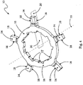
- the adapter 13 with its five support arms 14 is shown separately. It can be seen that the adapter 13 is designed in one piece and has a substantially ring-shaped support body 16 in addition to the support arms 14 .
- the carrier body 16 is provided here on its radial inside with a torque transmission profile 17, which is used, for example, to transmit drive torques to a freewheel driver 12a (not shown here) (cf. 12 ) a rear hub 8 of a bicycle 1 is used.
- the brackets 14 of the adapter 13 each have two mating planes or mating surfaces 18.
- the two mating surfaces 18 of each bracket 14, or the imaginary mating planes defined by the mating surfaces 18, are in relation to one another and to the axis of rotation 19 of the adapter 13 (which coincides with the axis of rotation 19 of the torque transmission assembly 9, cf. Figures 2, 3 and 12 ) containing imaginary plane 20 parallel.
- the imaginary plane 20, which is a median plane between the two mating planes 18, i.e. a plane which is parallel to each of the two mating planes 18 and is equidistant from each of the two mating surfaces 18, is in 4 indicated by a dashed line.
- FIG 5 shows the adapter 13 and the driving body 12 (in this case a pinion spider of a sprocket cassette 2, for example according to 2/3 ) in a situation shortly before the joining or pressing of driving body 12 and adapter 13. It can be seen that the ends of the support arms 14 of the adapter 13 are already arranged directly in the area of the supporting recesses 15 of the driving body 12.
- the driving body 12 in this case a pinion spider of a sprocket cassette 2, for example according to 2/3
- the adapter 13 is deliberately not arranged concentrically with respect to the driving body 12, but is shifted a little along the horizontal line, contrary to the direction of the arrow 21, relative to the drawing to the right. For the sake of better recognition, the extent of the shift is shown very greatly exaggerated.
- Shift 21 shown is intended to illustrate an inaccuracy or tolerance occurring before or during the joining process between driving body 12 and adapter 13 in the concentric positioning of driving body 12 and adapter 13, prior to the pressing of driving body 12 and adapter 13.
- Support arms 14 identified by the letter “D” and to a lesser extent also the support arms 14 identified by the letter “F” in relation to the generation of the movement or force required for the displacement 21 to the left together in the drawing.
- the support arm 14 marked with the letter “E” and, to a lesser extent also act in the sense of a parallel guidance between the driving body 12 and the adapter 13. This parallel guidance takes place in that the fitting surfaces 18 of the respective support arms 14 of the adapter 13 along the corresponding counter-fitting surfaces 22 (cf. 6 ) can slide.
- Figures 6 and 7 each show enlarged excerpts from the illustration according to FIG figure 5 , where the viewing direction is in Figures 6 and 7 a reverse direction related to the representation of figure 5 is equivalent to.
- one of the five support recesses 15 of the driving body 12 e.g. a pinion spider of a sprocket cassette 2 according to 2/3 .
- the support recess 15 has counter-fitting surfaces 22 on its inside, which are used to accommodate the lateral fitting surfaces 18 (cf. 4 / 5 ) are trained.
- 7 shows the same drawing section as 6 in a further enlarged view, where in 7 the adapter 13 is shown in its final, pressed position relative to the driving body 12.
- the mating surfaces of the driving body 12 and adapter 13 according to the present invention can also be on differently sized or non-round pitch circles, which can occur at any time due to, for example, manufacturing tolerances or hardening distortion on one or both parts, without this affecting the joining process, the quality the joint, or the concentricity of the joined parts is impaired. Rather, because of the amount of play 25, a relative positioning 27 of the support arm 14 and the support recess 15 that can be freely changed within the scope of the amount of play 25 is possible before and during the pressing.
- the radial direction 23 is the only directional component of the support arms 14 of the adapter 13 here, since the support arms 14, apart from their offset or dished base area 24, are arranged in a common plane, as is also shown in particular in FIG 4 is evident.
- the support arms 14, apart from their base area 24, run in radial directions in relation to the axis of rotation 19 of the assembly 9, and here in particular do not have any axial and/or circumferential directional components, as is the case, for example, with dished or easy spirally extending support arms, which are also encompassed by the present invention.
- the interference fit between the mating surfaces 22 ( 6 ) of the support recesses 15 of the driving body 12 and the fitting surfaces 18 accommodated therein ( 4 ) of the support arms 14 of the adapter 13 in the exemplary embodiment shown is selected in such a way that a clear formation of burrs 26 occurs when the driving body 12 and adapter 13 are pressed together, which is particularly evident at the points 26 in 7 is recognizable.
- the formation of burrs 26 means that when the support arms 14 of the adapter 13 are pressed into the support recesses 15 of the driving body 12, material is removed in a controlled manner.
- the driving body 12 and the adapter 13 have different material hardnesses.
- the driving body 12 e.g. if it is a pinion spider of a sprocket cassette
- the adapter 13 also acts as a punching or reaming tool when pressed into the support recesses 15 of the drive body 12, which finishes the fitting surfaces 22 of the support recesses 15 of the drive body 12 at the same time as the pressing process.
- This also works the other way around, ie when the material hardness of the driving body 12 is higher than that of the adapter 13 .
- the fitting surfaces 22 of the support recesses 15 of the driving body 12 form a punching or reaming tool, which in turn finishes the fitting surfaces 18 of the support arms 14 of the adapter 13 during pressing.
- This mutual finishing of the fitting surfaces on the respective other part is advantageous in that the requirements for the manufacturing or fitting accuracy of at least one of the two parts, and thus the manufacturing costs, can be reduced as a result.
- This also results in a particularly good reproducibility of the press fits between the driving body 12 and the adapter 13, and thus less rejects during production as well as a reduction in the number of components that may fail later in operation.
- the adapter 13 here has a dished shape insofar as an imaginary center plane of the carrier body 16 is arranged at a distance from an imaginary center plane of the support arms 14 along the assembly axis of rotation 19 .
- This dished design of the adapter 13 is advantageous in that it allows the support recesses 15 of the drive body 12 to be closed all around, which is particularly evident Figures 6 and 7 emerges, but also in 3 is evident.
- This all-round closed design of the support recesses 15 of the drive body 12 significantly increases the structural rigidity of the drive body 12 in the area of the support recesses 15, and thereby enables, among other things, a high surface pressure between the fitting surfaces 18 and 22 of adapter 13 and drive body 12, which in turn results in a highly resilient Press connection of adapter 13 and driving body 12 leads.
- FIG. 8 shows a highly schematic representation of various views of the embodiment according to FIG Figures 2 to 7 alternative embodiment of a torque transmission assembly 9.
- a driving body 12 and a Adapter 13 can be seen, the driving body 12 again having support recesses 15 and the adapter 13 again having support arms 14 .
- the main difference from the above embodiment according to Figures 2 to 7 is that the support arms 14 of the adapter 13 in accordance with the present embodiment 8 hardly protrude from the carrier body area 16 of the adapter 13, but are arranged essentially in the same radial distance area from the center or from the axis of rotation 19 of the assembly as the carrier body area 16.
- the torque transmission assembly 9 according to 8 similar to the adapter 13 (cf. 4 ) according to the torque transmission assembly Figures 2 to 7 , again a torque transmission profile 17, via which, for example, torque introduced from the driving body 12 via the adapter 13 to a connecting component, for example to a freewheel driver (cf. 12 ), on a bicycle crank or on a bicycle hub (cf. 1 ) can be transferred.
- a torque transmission profile 17 via which, for example, torque introduced from the driving body 12 via the adapter 13 to a connecting component, for example to a freewheel driver (cf. 12 ), on a bicycle crank or on a bicycle hub (cf. 1 ) can be transferred.
- FIGS 9 and 10 show further embodiments of torque transmission assemblies 9 in a highly schematic representation, each of which again comprises a driving body 12 and an adapter 13, with both driving body 12 and adapter 13 being completely flat in these embodiments.
- the adapter 13 also has a plurality of radially extending support arms 14, and the driving body 12 has a plurality of support recesses 15 that are complementary in position and shape to the support arms 14.
- the support arms 14 are again pressed into the support recesses 15, there being a degree of play 25 along the radial directions 23 between the support arm 14 and the support recess 15, as further above in particular with reference to FIG 7 described.
- self-centering is again achieved through the possibility of variable radial relative positioning 27 of the support arms 14 in the support recesses 15 and a pitch circle independence of the press connection between the driving body 12 and the adapter 13 .
- the difference between the embodiments according to 9 and 10 is that in the embodiment according to 9 the driving body 12 relative to the adapter 13 is arranged radially on the outside, while the driving body 12 in the embodiment according to 10 , Based on the adapter 13, is arranged radially on the inside. In both cases, however, the components that are pressed together, the driving body 12 and the adapter 13, form a torque transmission assembly 9 according to the present invention.
- the embodiments also shown schematically according to 11 and 12 correspond to the structural and functional principle with the above embodiments in essential properties, in particular with the embodiments according to Figures 9 and 10 .
- the adapter or the adapter device 13 according to the embodiments 11 and 12 not one piece is present as in the embodiments described above, but here in the form of a plurality of initially loose square pins.
- the loose parallelepiped pins not only form the support arms 14, but together they form the entire adapter 13.
- any dimensional tolerances such as hardening distortion and the like, can be easily compensated for when joining or pressing the adapter device 13 with the driving bodies 12a and 12b.
- the radially inner driving body 12b is a freewheel driver for a rear wheel hub 8 on a Bicycle 1 (cf. 1 ). It can be seen that in this way a driving body 12b, which is, for example, a cassette sprocket 10 or a sprocket spider 12 (cf. 2/3 ) can act, torque-transmitting fixed to the freewheel driver 12a can be connected. As with the embodiments described above, this connection is also fault-tolerant and low-stress, and due to the self-centering described above, it basically runs smoothly even if parts of the assembly should have manufacturing tolerances or distortion due to heat treatment.
Landscapes
- Engineering & Computer Science (AREA)
- Mechanical Engineering (AREA)
- General Engineering & Computer Science (AREA)
- Chemical & Material Sciences (AREA)
- Combustion & Propulsion (AREA)
- Transportation (AREA)
- Gears, Cams (AREA)
Claims (17)
- Module de transmission de couple (9) pour une bicyclette (1), comprenant un dispositif adaptateur (13) ainsi qu'au moins un corps d'entraînement (12) pouvant être relié de manière rigide au dispositif adaptateur (13) pour transmettre un couple, le dispositif adaptateur (13) présentant une pluralité d'au moins trois bras porteurs (14) s'étendant chacun avec une composante directionnelle radiale (23), l'au moins un corps d'entraînement (12) comprenant une pluralité correspondante d'évidements porteurs (15) complémentaires en position et en forme par rapport aux bras porteurs (14), un bras porteur (14) du dispositif adaptateur (13) pouvant respectivement être logé dans un évidement porteur (15) de l'au moins un corps d'entraînement (12) en formant un ajustement serré,
caractérisé en ce que
l'ajustement serré du bras porteur (14) et de l'évidement porteur (15) présente deux plans d'ajustement (18, 22), qui sont parallèles entre eux ainsi qu'à un plan imaginaire (20) contenant l'axe de rotation (19) du module (9), un jeu (25) étant présent entre le bras porteur (14) et l'évidement porteur (15) le long de la composante directionnelle radiale (23). - Module de transmission de couple (9) selon la revendication 1,
caractérisé en ce que
le plan imaginaire (20) forme un plan médian par rapport aux plans d'ajustement (18, 22). - Module de transmission de couple (9) selon la revendication 1 ou 2,
caractérisé en ce que
le dispositif adaptateur (13) est configuré en une seule pièce et comprend un corps de support (16) agencé radialement à l'intérieur ainsi que des bras porteurs (14), les bras porteurs (14) étant agencés en saillie radialement vers l'extérieur dans la zone de la périphérie extérieure du corps de support (16). - Module de transmission de couple (9) selon la revendication 1 ou 2,
caractérisé en ce que
le dispositif adaptateur (13) est configuré en une seule pièce et comprend un corps de support agencé radialement à l'extérieur ainsi que des bras porteurs (14), les bras porteurs (14) étant agencés en saillie vers l'intérieur dans la zone de la périphérie intérieure du corps de support. - Module de transmission de couple (9) selon l'une quelconque des revendications 1 à 4,
caractérisé en ce que
les bras porteurs (14) du dispositif adaptateur (13) sont agencés, au moins sur une partie de leur longueur, sur une surface de support (16a). - Module de transmission de couple (9) selon la revendication 1 ou 2,
caractérisé par
deux corps d'entraînement (12a/b) pouvant être agencés coaxialement l'un par rapport à l'autre à une distance radiale l'un de l'autre, comportant chacun des évidements porteurs (15a/b), les bras porteurs (14) étant configurés sous forme de goupilles parallélépipédiques, et chaque goupille parallélépipédique s'engageant par une première extrémité dans un évidement porteur (15a) du corps d'entraînement (12a) pouvant être agencé radialement à l'intérieur et par l'autre extrémité dans un évidement porteur (15b) du corps d'entraînement (12b) pouvant être agencé radialement à l'extérieur. - Module de transmission de couple (9) selon la revendication 4 ou 6,
caractérisé en ce que
le corps d'entraînement (12a) pouvant être agencé radialement à l'intérieur est un entraîneur à roue libre d'un moyeu de roue arrière de bicyclette. - Module de transmission de couple (9) selon l'une quelconque des revendications 1 à 6,
caractérisé en ce que
le dispositif adaptateur (13) présente une interface de transmission de couple (17) agencée radialement à l'intérieur. - Module de transmission de couple (9) selon l'une quelconque des revendications 1 à 8,
caractérisé en ce que
le dispositif adaptateur (13) est configuré sous forme concave, de telle sorte que des plans médians imaginaires du corps de support (16) et des bras porteurs (14) sont agencés à distance les uns des autres le long de l'axe de rotation (19) du module. - Module de transmission de couple (9) selon l'une quelconque des revendications 1 à 8,
caractérisé en ce que
l'au moins un corps d'entraînement (12) est configuré sous forme concave, de telle sorte que les plans d'ajustement (22) du corps d'entraînement et la sortie radialement intérieure des évidements porteurs (15) sont agencés à une distance les uns des autres le long de l'axe de rotation (19) du module. - Module de transmission de couple (9) selon l'une quelconque des revendications 1 à 10,
caractérisé en ce que
les évidements porteurs (15) de l'au moins un corps d'entraînement (12) sont fermés sur la périphérie. - Module de transmission de couple (9) selon l'une quelconque des revendications 1 à 11,
caractérisé en ce que
un corps d'entraînement (12, 12b) agencé radialement à l'extérieur par rapport au dispositif adaptateur (13) est une araignée destinée à recevoir au moins une roue à chaîne (10) d'une chaîne cinématique de bicyclette. - Module de transmission de couple (9) selon l'une quelconque des revendications 1 à 11,
caractérisé en ce que
un corps d'entraînement (12, 12b) agencé radialement à l'extérieur par rapport au dispositif adaptateur (13) est une roue à chaîne (10) d'une chaîne cinématique de bicyclette. - Module de transmission de couple (9) selon l'une quelconque des revendications 1 à 13,
caractérisé en ce que
le dispositif adaptateur (13) comporte cinq bras porteurs (14), et l'au moins un corps d'entraînement (12) présente en conséquence cinq évidements porteurs (15) . - Module de transmission de couple (9) selon l'une quelconque des revendications 1 à 14,
caractérisé en ce que
la dureté de matériau du dispositif adaptateur (13) est supérieure, au moins dans la zone des plans d'ajustement (18, 22), à la dureté de matériau du corps d'entraînement (12). - Module de transmission de couple (9) selon l'une quelconque des revendications 1 à 14,
caractérisé en ce que
la dureté de matériau du dispositif adaptateur (13) est inférieure, au moins dans la zone des plans d'ajustement (18, 22), à la dureté de matériau du corps d'entraînement (12). - Procédé de fabrication d'un module de transmission de couple (9) selon l'une quelconque des revendications 1 à 16, le procédé comprenant les étapes de procédé suivantes :a) la fabrication d'au moins un corps d'entraînement (12) et d'un dispositif adaptateur (13), de telle sorte que les surfaces d'ajustement (18) des bras porteurs (14) forment avec les surfaces d'ajustement (22) des évidements porteurs (15) du corps d'entraînement un surajustement au moins dans la plage de tolérance S à Z ;b) le positionnement du dispositif adaptateur (13) et du corps d'entraînement (12) axialement l'un au-dessus de l'autre le long de l'axe de rotation (19) du module, de telle sorte que les bras porteurs (14) recouvrent les évidements porteurs (15) ;c) l'assemblage par pression du dispositif adaptateur (13) et du corps d'entraînement (12) le long de l'axe de rotation (19) du module avec formation de bavures ou de copeaux (26) sur les surfaces d'ajustement (18, 22).
Applications Claiming Priority (1)
| Application Number | Priority Date | Filing Date | Title |
|---|---|---|---|
| DE102019002638.1A DE102019002638A1 (de) | 2019-04-10 | 2019-04-10 | Drehmomentübertragungsbaugruppe für ein Fahrrad |
Publications (2)
| Publication Number | Publication Date |
|---|---|
| EP3736201A1 EP3736201A1 (fr) | 2020-11-11 |
| EP3736201B1 true EP3736201B1 (fr) | 2022-05-04 |
Family
ID=69571753
Family Applications (1)
| Application Number | Title | Priority Date | Filing Date |
|---|---|---|---|
| EP20000061.0A Active EP3736201B1 (fr) | 2019-04-10 | 2020-02-10 | Module de transmission de couple pour une bicyclette |
Country Status (5)
| Country | Link |
|---|---|
| US (1) | US11465711B2 (fr) |
| EP (1) | EP3736201B1 (fr) |
| CN (1) | CN111806620B (fr) |
| DE (1) | DE102019002638A1 (fr) |
| TW (1) | TWI828869B (fr) |
Families Citing this family (1)
| Publication number | Priority date | Publication date | Assignee | Title |
|---|---|---|---|---|
| JP7117261B2 (ja) * | 2019-03-22 | 2022-08-12 | サンスター技研株式会社 | 回転伝達ディスク |
Family Cites Families (13)
| Publication number | Priority date | Publication date | Assignee | Title |
|---|---|---|---|---|
| JPS6018668Y2 (ja) * | 1979-04-13 | 1985-06-06 | 住友金属工業株式会社 | ブレ−キデイスク組立体 |
| US20030139240A1 (en) * | 2002-01-24 | 2003-07-24 | Chien-Liang Chen | Drive wheel for an exercise machine |
| US6994189B2 (en) * | 2003-03-18 | 2006-02-07 | Kun Teng Industry Co., Ltd | Brakable wheel hub device |
| US7654365B2 (en) * | 2006-02-21 | 2010-02-02 | Lamb Roger A | Two-piece floating disc brake assembly |
| DE102010040045A1 (de) * | 2010-08-31 | 2012-03-01 | Gustav Magenwirth Gmbh & Co. Kg | Geberarmatur und hydraulische Scheibenbremse |
| DE102011103489A1 (de) * | 2011-06-03 | 2012-12-06 | Sram Deutschland Gmbh | Mehrfach-Ritzelanordnung für eine Fahrradschaltung sowie Hinterrad-Achsanordnung mit einer derartigen Mehrfach-Ritzelanordnung |
| JP5649549B2 (ja) * | 2011-10-13 | 2015-01-07 | 株式会社シマノ | 自転車用駆動ユニット |
| DE102012009961A1 (de) * | 2012-05-19 | 2013-11-21 | Sram Deutschland Gmbh | Abschluss-Stützscheibe |
| DE102015203709A1 (de) | 2015-03-02 | 2016-09-08 | Sram Deutschland Gmbh | Ritzelanordnung mit Adapter |
| JP6453127B2 (ja) * | 2015-03-25 | 2019-01-16 | 株式会社シマノ | 自転車のドライブユニット |
| US9669900B2 (en) * | 2015-04-14 | 2017-06-06 | Shimano Inc. | Chain tensioning device |
| US10377445B2 (en) | 2016-09-20 | 2019-08-13 | Shimano Inc. | Bicycle front sprocket assembly |
| DE102017000855A1 (de) * | 2017-01-31 | 2018-08-02 | Sram Deutschland Gmbh | Mehrfach-Ritzelanordnung mit Schweißverbindung |
-
2019
- 2019-04-10 DE DE102019002638.1A patent/DE102019002638A1/de active Pending
-
2020
- 2020-02-10 EP EP20000061.0A patent/EP3736201B1/fr active Active
- 2020-02-21 TW TW109105724A patent/TWI828869B/zh active
- 2020-04-07 US US16/841,876 patent/US11465711B2/en active Active
- 2020-04-09 CN CN202010273275.8A patent/CN111806620B/zh active Active
Also Published As
| Publication number | Publication date |
|---|---|
| EP3736201A1 (fr) | 2020-11-11 |
| CN111806620B (zh) | 2023-05-02 |
| TW202037527A (zh) | 2020-10-16 |
| CN111806620A (zh) | 2020-10-23 |
| US11465711B2 (en) | 2022-10-11 |
| DE102019002638A1 (de) | 2020-10-15 |
| US20200324859A1 (en) | 2020-10-15 |
| TWI828869B (zh) | 2024-01-11 |
Similar Documents
| Publication | Publication Date | Title |
|---|---|---|
| EP1649196B1 (fr) | Porte-satellites pour boites de vitesses | |
| EP2239475B1 (fr) | Articulation à voies opposées | |
| WO2007051453A2 (fr) | Moyeu de roue pourvu d'evidements axiaux formes entre les trous destines a des boulons de roue | |
| DE102009039993A1 (de) | Antriebsanordnung für ein stufenlos verstellbares Getriebe eines Kraftfahrzeuges | |
| DE102013217753B3 (de) | Kupplungselement, Kupplungsanordnung sowie Verfahren zur Herstellung eines Kupplungselements | |
| DE3618130A1 (de) | Radlagerungs-gleichlaufgelenk-einheit | |
| DE19853798C1 (de) | Einrichtung zum Verbinden eines Wellenteiles mit einer Hülse | |
| EP3736201B1 (fr) | Module de transmission de couple pour une bicyclette | |
| DE112017005149T5 (de) | Gelenkwelle und herstellungsverfahren dafür | |
| DE19532519C2 (de) | Verfahren zur Herstellung eines rotationssymmetrischen metallischen Werkstücks | |
| DE10004419A1 (de) | Meßvorrichtung für eine angestellte Kegelrollenlagerung und Verfahren zur Herstellung einer angestellten Kegelrollenlagerung | |
| WO2007051452A1 (fr) | Moyeu de roue pourvu d'evidements axiaux formes entre les trous destines a des boulons de roue | |
| DE102008049978A1 (de) | Schalteinheit mit Kupplungskörper | |
| EP2811193B1 (fr) | Structure d'arbre pour une boîte de vitesse | |
| DE19929639B4 (de) | Welle-Nabe-Verbindung mit umgeformten Anschlagschrägen in Wellenverzahnung | |
| EP2834083B1 (fr) | Ensemble moyeu de roue et joint rotatif | |
| DE102013217755A1 (de) | Kupplungsanordnung, Kupplungselement sowie Verfahren zur Herstellung eines Kupplungselements | |
| EP3699442B1 (fr) | Arbre | |
| DE10290270B3 (de) | Anbringung einer radialen Flachscheibe an einer Nabe, insbesondere für eine Kupplungsscheibe eines Kraftfahrzeugs | |
| EP3179138B1 (fr) | Dispositif et procédé de liaison de deux parties rotatives de machine | |
| EP2395255B1 (fr) | Fixation axiale amovible de deux composants | |
| DE10008183C1 (de) | Baueinheit zur Lagerung und Antriebsverbindung eines Rades | |
| EP1527287B1 (fr) | Procédé de fabrication d'une liaison arbre-moyeu | |
| WO2005084971A1 (fr) | Barre antiroulis en deux parties pour un vehicule automobile et procede de fabrication de ladite barre antiroulis | |
| EP4368850A1 (fr) | Moyeu, en particulier pour bicyclettes |
Legal Events
| Date | Code | Title | Description |
|---|---|---|---|
| PUAI | Public reference made under article 153(3) epc to a published international application that has entered the european phase |
Free format text: ORIGINAL CODE: 0009012 |
|
| STAA | Information on the status of an ep patent application or granted ep patent |
Free format text: STATUS: THE APPLICATION HAS BEEN PUBLISHED |
|
| AK | Designated contracting states |
Kind code of ref document: A1 Designated state(s): AL AT BE BG CH CY CZ DE DK EE ES FI FR GB GR HR HU IE IS IT LI LT LU LV MC MK MT NL NO PL PT RO RS SE SI SK SM TR |
|
| AX | Request for extension of the european patent |
Extension state: BA ME |
|
| STAA | Information on the status of an ep patent application or granted ep patent |
Free format text: STATUS: REQUEST FOR EXAMINATION WAS MADE |
|
| 17P | Request for examination filed |
Effective date: 20210507 |
|
| GRAP | Despatch of communication of intention to grant a patent |
Free format text: ORIGINAL CODE: EPIDOSNIGR1 |
|
| STAA | Information on the status of an ep patent application or granted ep patent |
Free format text: STATUS: GRANT OF PATENT IS INTENDED |
|
| INTG | Intention to grant announced |
Effective date: 20211008 |
|
| GRAS | Grant fee paid |
Free format text: ORIGINAL CODE: EPIDOSNIGR3 |
|
| GRAA | (expected) grant |
Free format text: ORIGINAL CODE: 0009210 |
|
| STAA | Information on the status of an ep patent application or granted ep patent |
Free format text: STATUS: THE PATENT HAS BEEN GRANTED |
|
| AK | Designated contracting states |
Kind code of ref document: B1 Designated state(s): AL AT BE BG CH CY CZ DE DK EE ES FI FR GB GR HR HU IE IS IT LI LT LU LV MC MK MT NL NO PL PT RO RS SE SI SK SM TR |
|
| REG | Reference to a national code |
Ref country code: GB Ref legal event code: FG4D Free format text: NOT ENGLISH |
|
| REG | Reference to a national code |
Ref country code: CH Ref legal event code: EP |
|
| REG | Reference to a national code |
Ref country code: AT Ref legal event code: REF Ref document number: 1488803 Country of ref document: AT Kind code of ref document: T Effective date: 20220515 |
|
| REG | Reference to a national code |
Ref country code: IE Ref legal event code: FG4D Free format text: LANGUAGE OF EP DOCUMENT: GERMAN Ref country code: DE Ref legal event code: R096 Ref document number: 502020001021 Country of ref document: DE |
|
| REG | Reference to a national code |
Ref country code: NL Ref legal event code: FP |
|
| REG | Reference to a national code |
Ref country code: LT Ref legal event code: MG9D |
|
| PG25 | Lapsed in a contracting state [announced via postgrant information from national office to epo] |
Ref country code: SE Free format text: LAPSE BECAUSE OF FAILURE TO SUBMIT A TRANSLATION OF THE DESCRIPTION OR TO PAY THE FEE WITHIN THE PRESCRIBED TIME-LIMIT Effective date: 20220504 Ref country code: PT Free format text: LAPSE BECAUSE OF FAILURE TO SUBMIT A TRANSLATION OF THE DESCRIPTION OR TO PAY THE FEE WITHIN THE PRESCRIBED TIME-LIMIT Effective date: 20220905 Ref country code: NO Free format text: LAPSE BECAUSE OF FAILURE TO SUBMIT A TRANSLATION OF THE DESCRIPTION OR TO PAY THE FEE WITHIN THE PRESCRIBED TIME-LIMIT Effective date: 20220804 Ref country code: LT Free format text: LAPSE BECAUSE OF FAILURE TO SUBMIT A TRANSLATION OF THE DESCRIPTION OR TO PAY THE FEE WITHIN THE PRESCRIBED TIME-LIMIT Effective date: 20220504 Ref country code: HR Free format text: LAPSE BECAUSE OF FAILURE TO SUBMIT A TRANSLATION OF THE DESCRIPTION OR TO PAY THE FEE WITHIN THE PRESCRIBED TIME-LIMIT Effective date: 20220504 Ref country code: GR Free format text: LAPSE BECAUSE OF FAILURE TO SUBMIT A TRANSLATION OF THE DESCRIPTION OR TO PAY THE FEE WITHIN THE PRESCRIBED TIME-LIMIT Effective date: 20220805 Ref country code: FI Free format text: LAPSE BECAUSE OF FAILURE TO SUBMIT A TRANSLATION OF THE DESCRIPTION OR TO PAY THE FEE WITHIN THE PRESCRIBED TIME-LIMIT Effective date: 20220504 Ref country code: BG Free format text: LAPSE BECAUSE OF FAILURE TO SUBMIT A TRANSLATION OF THE DESCRIPTION OR TO PAY THE FEE WITHIN THE PRESCRIBED TIME-LIMIT Effective date: 20220804 |
|
| PG25 | Lapsed in a contracting state [announced via postgrant information from national office to epo] |
Ref country code: RS Free format text: LAPSE BECAUSE OF FAILURE TO SUBMIT A TRANSLATION OF THE DESCRIPTION OR TO PAY THE FEE WITHIN THE PRESCRIBED TIME-LIMIT Effective date: 20220504 Ref country code: PL Free format text: LAPSE BECAUSE OF FAILURE TO SUBMIT A TRANSLATION OF THE DESCRIPTION OR TO PAY THE FEE WITHIN THE PRESCRIBED TIME-LIMIT Effective date: 20220504 Ref country code: LV Free format text: LAPSE BECAUSE OF FAILURE TO SUBMIT A TRANSLATION OF THE DESCRIPTION OR TO PAY THE FEE WITHIN THE PRESCRIBED TIME-LIMIT Effective date: 20220504 Ref country code: IS Free format text: LAPSE BECAUSE OF FAILURE TO SUBMIT A TRANSLATION OF THE DESCRIPTION OR TO PAY THE FEE WITHIN THE PRESCRIBED TIME-LIMIT Effective date: 20220904 |
|
| PG25 | Lapsed in a contracting state [announced via postgrant information from national office to epo] |
Ref country code: SM Free format text: LAPSE BECAUSE OF FAILURE TO SUBMIT A TRANSLATION OF THE DESCRIPTION OR TO PAY THE FEE WITHIN THE PRESCRIBED TIME-LIMIT Effective date: 20220504 Ref country code: SK Free format text: LAPSE BECAUSE OF FAILURE TO SUBMIT A TRANSLATION OF THE DESCRIPTION OR TO PAY THE FEE WITHIN THE PRESCRIBED TIME-LIMIT Effective date: 20220504 Ref country code: RO Free format text: LAPSE BECAUSE OF FAILURE TO SUBMIT A TRANSLATION OF THE DESCRIPTION OR TO PAY THE FEE WITHIN THE PRESCRIBED TIME-LIMIT Effective date: 20220504 Ref country code: ES Free format text: LAPSE BECAUSE OF FAILURE TO SUBMIT A TRANSLATION OF THE DESCRIPTION OR TO PAY THE FEE WITHIN THE PRESCRIBED TIME-LIMIT Effective date: 20220504 Ref country code: EE Free format text: LAPSE BECAUSE OF FAILURE TO SUBMIT A TRANSLATION OF THE DESCRIPTION OR TO PAY THE FEE WITHIN THE PRESCRIBED TIME-LIMIT Effective date: 20220504 Ref country code: DK Free format text: LAPSE BECAUSE OF FAILURE TO SUBMIT A TRANSLATION OF THE DESCRIPTION OR TO PAY THE FEE WITHIN THE PRESCRIBED TIME-LIMIT Effective date: 20220504 Ref country code: CZ Free format text: LAPSE BECAUSE OF FAILURE TO SUBMIT A TRANSLATION OF THE DESCRIPTION OR TO PAY THE FEE WITHIN THE PRESCRIBED TIME-LIMIT Effective date: 20220504 |
|
| REG | Reference to a national code |
Ref country code: DE Ref legal event code: R097 Ref document number: 502020001021 Country of ref document: DE |
|
| PLBE | No opposition filed within time limit |
Free format text: ORIGINAL CODE: 0009261 |
|
| STAA | Information on the status of an ep patent application or granted ep patent |
Free format text: STATUS: NO OPPOSITION FILED WITHIN TIME LIMIT |
|
| PG25 | Lapsed in a contracting state [announced via postgrant information from national office to epo] |
Ref country code: AL Free format text: LAPSE BECAUSE OF FAILURE TO SUBMIT A TRANSLATION OF THE DESCRIPTION OR TO PAY THE FEE WITHIN THE PRESCRIBED TIME-LIMIT Effective date: 20220504 |
|
| 26N | No opposition filed |
Effective date: 20230207 |
|
| PG25 | Lapsed in a contracting state [announced via postgrant information from national office to epo] |
Ref country code: SI Free format text: LAPSE BECAUSE OF FAILURE TO SUBMIT A TRANSLATION OF THE DESCRIPTION OR TO PAY THE FEE WITHIN THE PRESCRIBED TIME-LIMIT Effective date: 20220504 |
|
| P01 | Opt-out of the competence of the unified patent court (upc) registered |
Effective date: 20230523 |
|
| PG25 | Lapsed in a contracting state [announced via postgrant information from national office to epo] |
Ref country code: MC Free format text: LAPSE BECAUSE OF FAILURE TO SUBMIT A TRANSLATION OF THE DESCRIPTION OR TO PAY THE FEE WITHIN THE PRESCRIBED TIME-LIMIT Effective date: 20220504 |
|
| REG | Reference to a national code |
Ref country code: CH Ref legal event code: PL |
|
| REG | Reference to a national code |
Ref country code: BE Ref legal event code: MM Effective date: 20230228 |
|
| PG25 | Lapsed in a contracting state [announced via postgrant information from national office to epo] |
Ref country code: LU Free format text: LAPSE BECAUSE OF NON-PAYMENT OF DUE FEES Effective date: 20230210 Ref country code: LI Free format text: LAPSE BECAUSE OF NON-PAYMENT OF DUE FEES Effective date: 20230228 Ref country code: CH Free format text: LAPSE BECAUSE OF NON-PAYMENT OF DUE FEES Effective date: 20230228 |
|
| REG | Reference to a national code |
Ref country code: IE Ref legal event code: MM4A |
|
| PG25 | Lapsed in a contracting state [announced via postgrant information from national office to epo] |
Ref country code: IT Free format text: LAPSE BECAUSE OF FAILURE TO SUBMIT A TRANSLATION OF THE DESCRIPTION OR TO PAY THE FEE WITHIN THE PRESCRIBED TIME-LIMIT Effective date: 20220504 Ref country code: IE Free format text: LAPSE BECAUSE OF NON-PAYMENT OF DUE FEES Effective date: 20230210 |
|
| PG25 | Lapsed in a contracting state [announced via postgrant information from national office to epo] |
Ref country code: BE Free format text: LAPSE BECAUSE OF NON-PAYMENT OF DUE FEES Effective date: 20230228 |
|
| PGFP | Annual fee paid to national office [announced via postgrant information from national office to epo] |
Ref country code: NL Payment date: 20240219 Year of fee payment: 5 |
|
| PGFP | Annual fee paid to national office [announced via postgrant information from national office to epo] |
Ref country code: DE Payment date: 20240229 Year of fee payment: 5 |
|
| PGFP | Annual fee paid to national office [announced via postgrant information from national office to epo] |
Ref country code: FR Payment date: 20240222 Year of fee payment: 5 |
|
| GBPC | Gb: european patent ceased through non-payment of renewal fee |
Effective date: 20240210 |