EP3734087B1 - Spannschloss und box für led-anzeigebildschirm - Google Patents
Spannschloss und box für led-anzeigebildschirm Download PDFInfo
- Publication number
- EP3734087B1 EP3734087B1 EP20705123.6A EP20705123A EP3734087B1 EP 3734087 B1 EP3734087 B1 EP 3734087B1 EP 20705123 A EP20705123 A EP 20705123A EP 3734087 B1 EP3734087 B1 EP 3734087B1
- Authority
- EP
- European Patent Office
- Prior art keywords
- shim
- knob
- base
- rotating shaft
- hole
- Prior art date
- Legal status (The legal status is an assumption and is not a legal conclusion. Google has not performed a legal analysis and makes no representation as to the accuracy of the status listed.)
- Active
Links
Images



Classifications
-
- G—PHYSICS
- G09—EDUCATION; CRYPTOGRAPHY; DISPLAY; ADVERTISING; SEALS
- G09F—DISPLAYING; ADVERTISING; SIGNS; LABELS OR NAME-PLATES; SEALS
- G09F9/00—Indicating arrangements for variable information in which the information is built-up on a support by selection or combination of individual elements
- G09F9/30—Indicating arrangements for variable information in which the information is built-up on a support by selection or combination of individual elements in which the desired character or characters are formed by combining individual elements
- G09F9/302—Indicating arrangements for variable information in which the information is built-up on a support by selection or combination of individual elements in which the desired character or characters are formed by combining individual elements characterised by the form or geometrical disposition of the individual elements
- G09F9/3026—Video wall, i.e. stackable semiconductor matrix display modules
-
- E—FIXED CONSTRUCTIONS
- E05—LOCKS; KEYS; WINDOW OR DOOR FITTINGS; SAFES
- E05C—BOLTS OR FASTENING DEVICES FOR WINGS, SPECIALLY FOR DOORS OR WINDOWS
- E05C5/00—Fastening devices with bolts moving otherwise than only rectilinearly and only pivotally or rotatively
- E05C5/02—Fastening devices with bolts moving otherwise than only rectilinearly and only pivotally or rotatively both moving axially and turning about their axis to secure the wing
- E05C5/04—Fastening devices with bolts moving otherwise than only rectilinearly and only pivotally or rotatively both moving axially and turning about their axis to secure the wing performing both movements simultaneously, e.g. screwing into a keeper
-
- F—MECHANICAL ENGINEERING; LIGHTING; HEATING; WEAPONS; BLASTING
- F16—ENGINEERING ELEMENTS AND UNITS; GENERAL MEASURES FOR PRODUCING AND MAINTAINING EFFECTIVE FUNCTIONING OF MACHINES OR INSTALLATIONS; THERMAL INSULATION IN GENERAL
- F16B—DEVICES FOR FASTENING OR SECURING CONSTRUCTIONAL ELEMENTS OR MACHINE PARTS TOGETHER, e.g. NAILS, BOLTS, CIRCLIPS, CLAMPS, CLIPS OR WEDGES; JOINTS OR JOINTING
- F16B2/00—Friction-grip releasable fastenings
- F16B2/02—Clamps, i.e. with gripping action effected by positive means other than the inherent resistance to deformation of the material of the fastening
- F16B2/18—Clamps, i.e. with gripping action effected by positive means other than the inherent resistance to deformation of the material of the fastening using cams, levers, eccentrics, or toggles
-
- F—MECHANICAL ENGINEERING; LIGHTING; HEATING; WEAPONS; BLASTING
- F16—ENGINEERING ELEMENTS AND UNITS; GENERAL MEASURES FOR PRODUCING AND MAINTAINING EFFECTIVE FUNCTIONING OF MACHINES OR INSTALLATIONS; THERMAL INSULATION IN GENERAL
- F16B—DEVICES FOR FASTENING OR SECURING CONSTRUCTIONAL ELEMENTS OR MACHINE PARTS TOGETHER, e.g. NAILS, BOLTS, CIRCLIPS, CLAMPS, CLIPS OR WEDGES; JOINTS OR JOINTING
- F16B21/00—Means for preventing relative axial movement of a pin, spigot, shaft or the like and a member surrounding it; Stud-and-socket releasable fastenings
- F16B21/02—Releasable fastening devices locking by rotation
- F16B21/04—Releasable fastening devices locking by rotation with bayonet catch
-
- G—PHYSICS
- G09—EDUCATION; CRYPTOGRAPHY; DISPLAY; ADVERTISING; SEALS
- G09F—DISPLAYING; ADVERTISING; SIGNS; LABELS OR NAME-PLATES; SEALS
- G09F9/00—Indicating arrangements for variable information in which the information is built-up on a support by selection or combination of individual elements
- G09F9/30—Indicating arrangements for variable information in which the information is built-up on a support by selection or combination of individual elements in which the desired character or characters are formed by combining individual elements
- G09F9/33—Indicating arrangements for variable information in which the information is built-up on a support by selection or combination of individual elements in which the desired character or characters are formed by combining individual elements being semiconductor devices, e.g. diodes
-
- H—ELECTRICITY
- H05—ELECTRIC TECHNIQUES NOT OTHERWISE PROVIDED FOR
- H05K—PRINTED CIRCUITS; CASINGS OR CONSTRUCTIONAL DETAILS OF ELECTRIC APPARATUS; MANUFACTURE OF ASSEMBLAGES OF ELECTRICAL COMPONENTS
- H05K5/00—Casings, cabinets or drawers for electric apparatus
- H05K5/02—Details
- H05K5/0217—Mechanical details of casings
- H05K5/0221—Locks; Latches
-
- H—ELECTRICITY
- H05—ELECTRIC TECHNIQUES NOT OTHERWISE PROVIDED FOR
- H05K—PRINTED CIRCUITS; CASINGS OR CONSTRUCTIONAL DETAILS OF ELECTRIC APPARATUS; MANUFACTURE OF ASSEMBLAGES OF ELECTRICAL COMPONENTS
- H05K5/00—Casings, cabinets or drawers for electric apparatus
- H05K5/02—Details
- H05K5/03—Covers
-
- H—ELECTRICITY
- H05—ELECTRIC TECHNIQUES NOT OTHERWISE PROVIDED FOR
- H05K—PRINTED CIRCUITS; CASINGS OR CONSTRUCTIONAL DETAILS OF ELECTRIC APPARATUS; MANUFACTURE OF ASSEMBLAGES OF ELECTRICAL COMPONENTS
- H05K5/00—Casings, cabinets or drawers for electric apparatus
- H05K5/10—Casings, cabinets or drawers for electric apparatus comprising several parts forming a closed casing
-
- F—MECHANICAL ENGINEERING; LIGHTING; HEATING; WEAPONS; BLASTING
- F16—ENGINEERING ELEMENTS AND UNITS; GENERAL MEASURES FOR PRODUCING AND MAINTAINING EFFECTIVE FUNCTIONING OF MACHINES OR INSTALLATIONS; THERMAL INSULATION IN GENERAL
- F16B—DEVICES FOR FASTENING OR SECURING CONSTRUCTIONAL ELEMENTS OR MACHINE PARTS TOGETHER, e.g. NAILS, BOLTS, CIRCLIPS, CLAMPS, CLIPS OR WEDGES; JOINTS OR JOINTING
- F16B5/00—Joining sheets or plates, e.g. panels, to one another or to strips or bars parallel to them
- F16B5/06—Joining sheets or plates, e.g. panels, to one another or to strips or bars parallel to them by means of clamps or clips
- F16B5/0607—Joining sheets or plates, e.g. panels, to one another or to strips or bars parallel to them by means of clamps or clips joining sheets or plates to each other
- F16B5/0621—Joining sheets or plates, e.g. panels, to one another or to strips or bars parallel to them by means of clamps or clips joining sheets or plates to each other in parallel relationship
Definitions
- the application belongs to the technical field of LED display screen box assembly, in particular to a tension lock used for LED displays and an LED display screen box.
- the LED display box usually includes an LED display module and a power module.
- the power module is provided with a pin header, and the LED display module is provided with a female header.
- the power module is installed on the LED display module through the plug-in between the pin header and the female header.
- a Chinese patent ( CN 208456969 U ) proposes a press-rotating lock and a connecting lock catch structure for quick disassembly, which is convenient to install, time-saving and labor-saving, and is convenient for quick assembly of a display screen.
- a US patent ( US 9850928 B2 ) provides a fastener for securing together two panels, which could be used to secure together various types of components of structures, machines etc.
- the aim of the application is to provide a tension lock and an LED display screen box to solve the technical problem that the installation mode of the existing LED display screen box is time-consuming and laborious.
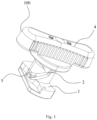
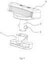
- the present invention provides a tension lock according to claim 1, which comprises a base, a rotating shaft, a shim and a knob, wherein a sliding hole is arranged on the base, one end of the rotating shaft is fixedly connected with the knob, the other end of the rotating shaft is inserted into the sliding hole, the shim is rotationally connected to the rotating shaft, and the shim is abutted against the knob;the distance between the shim and the knob is kept constant;
- the rotating shaft rotates and slides along the axial direction of the sliding hole, so that the shim is away from or close to the base.
- the base can be fixedly connected with the box frame, and the shim can be fixedly connected with the rear cover.
- the knob when the rotating shaft slides along the axial direction of the sliding hole toward the base, the shim gradually approaches the base, and the shim will drive the rear cover to gradually approach the box frame to assist the connection between the rear cover and the box frame; when the rotating shaft slides along the axial direction of the sliding hole in a direction away from the base, the shim gradually moves away from the base, and the shim will drive the rear cover to gradually move away from the box frame, so as to gradually remove the connection between the rear cover and the box frame, to separate the rear cover and the box frame from each other.
- installation and disassembly of LED display screen box are faster and more convenient, and the installation efficiency of LED display screen box is effectively improved.
- the knob comprises a contact piece and a handle fixedly connected to the contact piece, and the another side surface of the shim is abutted against the side surface of the contact piece facing away from the handle.
- the shim is provided with a first through hole, and the shim is sleeved on the small tube section through the first through hole.
- one side of the knob close to the base is provided with a clamping hole, and the small tube section is clamped in the clamping hole.
- a clamping slot is formed on outer side wall of the small tube section, and a block matched with the clamping slot is formed on inner side wall of the clamping hole.
- the tension lock further comprises a bolt installed on the rotating shaft;
- the rotating shaft is provided with a second through hole
- the bolt is installed in the second through hole
- the axis of the bolt is perpendicular to that of the rotating shaft.
- the embodiment of the present application also provides an LED display screen box, comprising a rear cover, a power module, an LED display module, a box frame and a tension lock described above, wherein the box frame is fixedly connected with the LED display module, the power module is installed in the rear cover and located between the rear cover and the box frame, and one side of the power module facing the LED display module is provided with a pin header, the LED display module is provided with a female header matched with the pin header, the box frame is provided with a via hole at a position corresponding to the female header, and the pin header can pass through the via hole and be plugged into the female header;
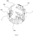
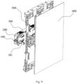
- the LED display screen box provided by the embodiment of the present application includes a rear cover 200, a power module 300, an LED display module 400, a box frame 500, and a tension lock 100.
- the box frame 500 is fixedly connected with the LED display module 400, and the power module 300 is installed in the rear cover 200 and located between the rear cover 200 and the box frame 500.
- One side of the power module 300 facing the LED display module 400 is provided with a pin header 301, and the LED display module 400 is provided with a female header 401 matched with the pin header 301.
- the box frame 500 is provided with a via hole 501 at a position corresponding to the female header 401, and the pin header 301 can pass through the via hole 501 and be plugged into the female header 401.
- the base 1 is fixedly connected to the box frame 500 and the shim 3 is fixedly connected to the power module 300.
- the rotating shaft 2 rotates and slides along the axial direction of the sliding hole 121, so that the shim 3 is away from or close to the base 1.
- base 1 is fixedly connected to box frame 500 and shim 3 is fixedly connected to rear cover 200.
- shim 3 will gradually approach base 1, and shim 3 will drive rear cover 200 to gradually approach box frame 500 to assist the connection between rear cover 200 and box frame 500.
- the installation and disassembly of the LED display screen box can be faster and more convenient, and the installation efficiency of the LED display screen box can be effectively improved.
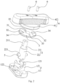
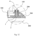
- the rotating shaft 2 comprises a small tube section 21 and a large tube section 22, wherein the small tube section 21 is fixedly connected with the knob 4, and the large tube section 22 is inserted into the sliding hole 121 and can slide along the axial direction of the sliding hole 121.
- a step surface 23 is formed between the small tube section 21 and the large tube section 22, one side surface of the shim 3 is abutted against the step surface 23, and the other side surface of the shim 3 is abutted against the knob 4.
- the knob 4 includes a contact piece 41 and a handle 42 fixedly connected to the contact piece 41, and the other side surface of the shim 3 abuts against the side surface of the contact piece 41 facing away from the handle 42.
- the handle 42 makes it is easy to turn the knob 4.
- the surface on which the contact piece 41 abuts the shim 3 is flat, so that the contact between the shim 3 and the contact piece 41 is more stable, and the shim 3 is more stably driven to move.
- the shim 3 is provided with a first through hole 31, and the shim 3 is sleeved on the small tube section 21 through the first through hole 31 to, so that the shim 3 can be rotationally connected to the rotating shaft 2, and the distance between the shim 3 and the knob 4 can be kept constant.
- a clamping hole 43 is provided on one side of the knob 4 close to the base 1, and the small tube section 21 is clamped in the clamping hole 43 to fixedly connect the rotating shaft 2 with the knob 4.
- a clamping slot 211 is formed on the outer side wall of the small tube section 21, and a block matched with the clamping slot 211 is formed on the inner side wall of the clamping hole 43 so as to clamp the small tube section 21 in the clamping hole 43.
- the tension lock 100 further includes a bolt 5 installed on the rotating shaft 2.
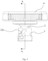
- the base 1 includes a base plate 11 and a base column 12 connected to the base plate 11, the sliding hole 121 is arranged on the base column 12, the axis of the sliding hole 121 is perpendicular to the base plate 11, and the side wall of the base column 12 is provided with a sliding groove 122 communicated with the sliding hole 121.
- the bolt 5 can slide along the sliding groove 122 to make the rotating shaft 2 slide in the axial direction of the sliding hole 121.
- the sliding groove 122 is obliquely disposed on the side wall of the base column 12.
- the bolt 5 will first slide into the sliding groove 122 toward an opening of the knob 4.
- the bolt 5 will slide along the sliding groove 122 to the side of the sliding groove 122 facing away from the knob 4, so as to make the shim 3 gradually approach the base 1, thereby driving the rear cover 200 to move to the LED display module 400, and plugging the pin header 301 to the female header 401, thus completing the installation of the LED display screen box.
- the rotating shaft 2 is provided with a second through hole 221
- the bolt 5 is installed in the second through hole 221
- the axis of the bolt 5 is perpendicular to the axis of the rotating shaft 2 to facilitate setting the sliding groove 122 and making the bolt 5 slides along the sliding groove 122.
- the tension lock 100 further includes an elastomeric bead 6 mounted on the knob 4.
- the surface of the shim 3 facing the knob 4 is provided with a first bead slot 32 and a second bead slot 33.
- the elastomeric bead 6 can be slid from the first bead slot 32 to the second bead slot 33.
- the elastomeric bead 6 can be slid from the second bead slot 33 to the first bead slot 32.
- the elastomeric bead 6 and shim 3 are matched by a clamping point, and the elastomeric bead 6 adopts an extrudable elastic structure to strengthen hand feeling and facilitate the locking effect.
- two elastomeric beads 6 are provided, correspondingly, two first slots 32 and two second slots 33 are provided.
- the central connecting line of the two first slots 32 is perpendicular to the central connecting line of the two second slots 33, so that the knob 4 can be locked after rotating at 90° , thus realizing the auxiliary installation of the LED box.
- the setting of the sliding groove 122 should ensure that when the knob 4 rotates 90 degree, the bolt 5 can slide from the sliding groove 122 toward an opening of the knob 4 to the side of the sliding groove 122 facing away from the knob 4.
- the distance that the knob 4 moves along the axial direction of the sliding hole121 should not be less than the length of the pin header 301, so as to realize complete plug-in between the pin header 301 and the female header 401.
- the shim 3 is provided with a fixing hole 34, the shim 3 is fixedly connected to the rear cover 200 through the fixing hole 34, and the base 1 is fixedly connected to the box frame 500.
Landscapes
- Engineering & Computer Science (AREA)
- General Engineering & Computer Science (AREA)
- Physics & Mathematics (AREA)
- General Physics & Mathematics (AREA)
- Theoretical Computer Science (AREA)
- Microelectronics & Electronic Packaging (AREA)
- Mechanical Engineering (AREA)
- Multimedia (AREA)
- Devices For Indicating Variable Information By Combining Individual Elements (AREA)
- Casings For Electric Apparatus (AREA)
- Illuminated Signs And Luminous Advertising (AREA)
Claims (8)
- Eine Spannungsarretierung (100) für LED-Anzeigen, die eine Grundfläche (1), einen Drehschaft (2), eine Unterlegscheibe (3) und einen Knopf (4) umfasst, wobei die Grundfläche (1) mit einem Gleitloch (121) versehen ist, ein Ende des Drehschafts (2) fest mit dem Knopf (4) verbunden ist, das andere Ende des Drehschafts (2) in das Gleitloch (121) eingeschoben ist, die Unterlegscheibe (3) drehbar mit dem Drehschaft (2) verbunden ist und die Unterlegscheibe (3) gegen den Knopf (4) stösst, der Abstand zwischen der Unterlegscheibe (3) und dem Kopf (4) konstant gehalten wird;der Knopf (4) kann gedreht werden, um den Drehschaft (2) zu drehen und damit dieser längs der Axialrichtung des Gleitloches (121) gleitet, so dass die Unterlegscheibe (3) sich weg von oder nahe hin zur Grundfläche (1) bewegen kann;wobei der Drehschaft (2) einen kleinen Rohrabschnitt (21) und einen grossen Rohrabschnitt (22) umfasst, der kleine Rohrabschnitt (21) fest mit dem Knopf (4) verbunden ist und der grosse Rohrabschnitt (22) in das Gleitloch (121) eingeschoben ist und längs der Axialrichtung des Gleitloches (121) gleitet;eine Stufenfläche (23) zwischen dem kleinen Rohrabschnitt (21) und dem grossen Rohrabschnitt (22) geformt ist, eine Seitenfläche der Unterlegscheibe (3) gegen die Stufenfläche (23) anliegt und eine andere Seitenfläche der Unterlegscheibe (3) am Knopf (4) anliegt;dadurch gekennzeichnet, dass die Spannungsarretierung (100) ausserdem einen am Knopf (4) angebrachten elastomerischen Rundstab aufweist;einen ersten Schlitz (32) für den Rundstab und einen zweiten Schlitz (33) für den Rundstab, die an einer Seitenfläche der hin zum Knopf (4) gerichteten Unterlegscheibe (3) angeordnet sind; unddass, wenn der Knopf (4) dreht wird, um die Unterlegscheibe (3) von der Grundfläche (1) wegzubewegen, der elastomerische Rundstab (6) weg vom ersten Schlitz (32) für den Rundstab hin zum zweiten Schlitz (33) für den Rundstab gleiten kann; dass wenn der Knopf (4) gedreht wird, um die Unterlegscheibe (3) in die Nähe der Grundfläche (1) zu bewegen, der elastomerische Rundstab (6) von dem zweiten Schlitz (33 ) für den Rundstab zum ersten Schlitz (32) für den Rundstab gleiten kann.
- Die Spannungsarretierung (100) gemäss Anspruch 1, bei der der Knopf (4) ein Kontaktstück (41) und einen fest mit dem Kontaktstück (41) verbundenen Griff (42) umfasst, und wobei die andere Seitenfläche der Unterlegscheibe (3) gegen die vom Griff (42) abgewandte Seitenfläche des Kontaktstücks (41) stösst.
- Die Spannungsarretierung (100) gemäss Anspruch 1, bei der die Unterlegscheibe (3) mit einem ersten Durchgangsloch (31) versehen ist und die Unterlegscheibe (3) durch das erste Durchgangsloch (31) über einen kleinen Rohrabschnitt (21) gestreift ist.
- Die Spannungsarretierung (100) gemäss Anspruch 1, bei der eine, nahe der Grundfläche (1) gelegene Seite des Knopfes (4) mit einem Klemmloch (43) versehen ist und der kleine Rohrabschnitt (21) im Klemmloch (43) fesgeklemmt ist.
- Die Spannungsarretierung (100) gemäss Anspruch 4, bei der ein Klemmspalt (211) an der Aussenseitenwand des kleinen Rohrabschnittes (21) geformt ist und ein dem Klemmspalt (211) angepasster Block an der Innenseitenwand des Klemmloches (43) geformt ist.
- Die Spannungsarretierung (100) gemäss Anspruch 1, wobei die Spannungsarretierung (100) weiter einen am Drehschaft (2) montierten Bolzen (5) umfasst;bei der die Grundfläche (1) eine Grundplatte (11) und eine Fussstütze (12) umfasst, die mit der Grundplatte (11) verbunden ist, wobei das Gleitloch (121) an der Fussstütze (12) angeordnet ist, die Achse des Gleitloches (121) senkrecht zu der Grundplatte (11) verläuft und die Seitenwand der Fussstütze (12) über einen Gleitschlitz (122) verfügt, der mit dem Gleitloch (121) kommuniziert;wobei, wenn der Drehschaft (2) sich dreht, der Bolzen (5) längs des Gleitschlitzes (122) gleiten kann, um den Drehschaft (2) zum Gleiten längs der Axialrichtung des Gleichloches (121) zu bringen.
- Eine Spannungsarretierung (100) gemäss Anspruch 6, bei der der Drehschaft (2) mit einem zweiten Durchgangsloch (221) versehen ist, der Bolzen (5) im zweiten Durchgangsloch (221) installiert ist und die Bolzenachse (5) senkrecht zu der des Drehschaftes (2) verläuft.
- Ein LED-Anzeigebildschirmgehäuse, das eine hintere Abdeckung (200), ein Energiemodul (300), ein LED-Anzeigemodul (400), einen Gehäuserahmen (500) und eine Spannungsarretierung (100) übereinstimmend mit irgendeinem der Ansprüche 1 bis 7 umfasst,wobei der Gehäuserahmen (500) fest mit dem LED-Anzeigemodul (400) verbunden ist, das Energiemodul (300) in der hinteren Abdeckung (200) installiert und zwischen der hinteren Abdeckung (200) und dem Gehäuserahmen angeordnet ist, und eine Seite des Energiemoduls (300), das zum LED-Anzeigemodul (400) hin gerichtet ist, mit einer Stiftleiste (301) versehen ist, das LED-Anzeigemodul (400) mit einer Buchsenleiste (401) ausgerüstet ist, die der Stiftleiste (301) angepasst ist, der Gehäuserahmen (500) mit einem Durchgangsloch (501) in einer der Buchsenleiste (401) entsprechenden Lage versehen ist, und die Stiftleiste (301) durch das Durchgangsloch (501) und in die Buchsenleiste gesteckt werden kann;wobei die Grundfläche (1) fest mit dem Gehäuseahmen (500) verbunden ist und die Unterlegscheibe (3) fest mit der hinteren Abdeckung (200) verbunden ist;wobei, wenn der Knopf (4) gedreht wird, um die Unterlegscheibe (3) näher an die Grundfläche (1) zu bringen, sich die hintere Abdeckung (200) hin zum LED-Anzeigemodul (400) bewegt, damit die Stiftleiste (301) in die Buchsenleiste (401) eingesteckt werden kann, wenn der Knopf (4) gedreht wird, damit die Unterlegscheibe (3) weg bewegt wird von der Grundfläche (1), bewegt sich die hintere Abdeckung (200) in einer Richtung weg vom LED-Anzeigemodul (400) um die Stiftleiste (301) aus der Buchsenleiste (401) zu ziehen.
Applications Claiming Priority (2)
| Application Number | Priority Date | Filing Date | Title |
|---|---|---|---|
| CN201910164352.3A CN109931317B (zh) | 2019-03-05 | 2019-03-05 | 拉紧锁以及led显示屏箱体 |
| PCT/CN2020/072989 WO2020177494A1 (zh) | 2019-03-05 | 2020-01-19 | 拉紧锁以及led显示屏箱体 |
Publications (3)
| Publication Number | Publication Date |
|---|---|
| EP3734087A1 EP3734087A1 (de) | 2020-11-04 |
| EP3734087A4 EP3734087A4 (de) | 2021-09-01 |
| EP3734087B1 true EP3734087B1 (de) | 2023-05-10 |
Family
ID=66986466
Family Applications (1)
| Application Number | Title | Priority Date | Filing Date |
|---|---|---|---|
| EP20705123.6A Active EP3734087B1 (de) | 2019-03-05 | 2020-01-19 | Spannschloss und box für led-anzeigebildschirm |
Country Status (4)
| Country | Link |
|---|---|
| US (1) | US11350533B2 (de) |
| EP (1) | EP3734087B1 (de) |
| CN (1) | CN109931317B (de) |
| WO (1) | WO2020177494A1 (de) |
Families Citing this family (7)
| Publication number | Priority date | Publication date | Assignee | Title |
|---|---|---|---|---|
| CN109931317B (zh) * | 2019-03-05 | 2024-10-18 | 深圳市光祥科技股份有限公司 | 拉紧锁以及led显示屏箱体 |
| US11885091B2 (en) | 2021-06-30 | 2024-01-30 | Reynolds Presto Products Inc. | Connection device for fastening expanded cell confinement structures and methods for doing the same |
| CN113888990B (zh) * | 2021-09-07 | 2024-12-27 | 深圳利亚德光电有限公司 | 箱体的拉紧机构及具有其的led箱体组件 |
| CN113903272B (zh) * | 2021-09-29 | 2024-10-22 | 深圳利亚德光电有限公司 | Led显示装置 |
| DE102022111105A1 (de) * | 2022-05-05 | 2023-11-09 | Sma Solar Technology Ag | Gehäuse für ein elektrisches gerät mit einem deckel |
| CN116741912B (zh) * | 2023-08-11 | 2023-10-10 | 宜宾精显电子科技有限公司 | 一种led显示屏 |
| CN116951251B (zh) * | 2023-09-21 | 2023-12-15 | 国网山西省电力公司物资分公司 | 一种招标信息数据显示的液晶屏装配结构 |
Family Cites Families (30)
| Publication number | Priority date | Publication date | Assignee | Title |
|---|---|---|---|---|
| US6408659B1 (en) * | 2000-12-06 | 2002-06-25 | Handyway Co., Ltd. | Quick lock |
| CN2714869Y (zh) * | 2003-11-17 | 2005-08-03 | 江门市婴宝婴儿用品有限公司 | 一种管件连接器 |
| TWM254062U (en) * | 2004-02-06 | 2004-12-21 | Hon Hai Prec Ind Co Ltd | Hinge assembly |
| TWM331275U (en) * | 2007-08-01 | 2008-04-21 | Jarllytec Co Ltd | Stopping device of rotating shaft structure |
| US20110027038A1 (en) * | 2009-07-28 | 2011-02-03 | Pen-Chun YU | Heat sink anchoring apparatus |
| US20120227257A1 (en) * | 2011-03-07 | 2012-09-13 | Kalavitz Michael V | Coupler device |
| US20130104342A1 (en) * | 2011-10-27 | 2013-05-02 | Sony Mobile Communications Japan, Inc. | Mobile terminal |
| CN103362912B (zh) * | 2012-03-29 | 2016-09-07 | 海洋王(东莞)照明科技有限公司 | 伸缩结构、套筒及插接杆 |
| CN103379785A (zh) * | 2012-04-20 | 2013-10-30 | 鸿富锦精密工业(深圳)有限公司 | 固定装置 |
| US8708595B2 (en) * | 2012-09-05 | 2014-04-29 | Hanwit Precision Industries Ltd. | Panel member locking device |
| CN203055361U (zh) * | 2012-12-28 | 2013-07-10 | 深圳市大族元亨光电股份有限公司 | 一种单元屏的上下连接结构 |
| CN203655812U (zh) * | 2013-12-25 | 2014-06-18 | 广东洲明节能科技有限公司 | 连接结构 |
| US20150300398A1 (en) * | 2014-04-18 | 2015-10-22 | Hanwit Precision Industries Ltd. | Rotary fastener |
| CN205104166U (zh) * | 2014-04-21 | 2016-03-23 | 冉启洁 | 带锁盒的显示屏安装结构 |
| CN204003886U (zh) * | 2014-06-13 | 2014-12-10 | 深圳市奥拓电子股份有限公司 | 电源盒快速锁紧装置 |
| WO2016205282A1 (en) * | 2015-06-15 | 2016-12-22 | Antosh Kevin M | Helical-drive captive-panel fastener assembly |
| US9850928B2 (en) * | 2015-09-10 | 2017-12-26 | Ned C. Bowers | Fastener for securing together two panels |
| CN105508352B (zh) * | 2016-01-12 | 2017-12-08 | 深圳市奥拓电子股份有限公司 | 锁扣组件和led拼装屏 |
| CN105485105B (zh) * | 2016-01-22 | 2018-02-02 | 深圳利亚德光电有限公司 | 连接结构及具有其的led显示装置 |
| KR101718141B1 (ko) * | 2016-02-16 | 2017-03-21 | 제이에스엘씨디(주) | 프레임 어셈블리를 구비한 디스플레이 장치 |
| CN107120346B (zh) * | 2017-05-24 | 2022-10-28 | 深圳市雷迪奥视觉技术有限公司 | 一种快锁件、显示屏组合件 |
| CN107061437B (zh) * | 2017-06-12 | 2022-12-30 | 湖南明和光电设备有限公司 | 模块连接结构及led显示屏 |
| CN207182822U (zh) * | 2017-07-17 | 2018-04-03 | 深圳市洲明科技股份有限公司 | 一种led显示屏 |
| CN208153474U (zh) * | 2018-03-14 | 2018-11-27 | 深圳市洲明科技股份有限公司 | 一种弧形锁扣以及显示屏 |
| CN208456969U (zh) * | 2018-06-29 | 2019-02-01 | 深圳市恒丰精密五金有限公司 | 压旋式锁体 |
| CN208477863U (zh) * | 2018-07-27 | 2019-02-05 | 深圳市艾比森光电股份有限公司 | Led显示屏 |
| CN109931317B (zh) * | 2019-03-05 | 2024-10-18 | 深圳市光祥科技股份有限公司 | 拉紧锁以及led显示屏箱体 |
| CN209892567U (zh) * | 2019-03-05 | 2020-01-03 | 深圳市光祥科技股份有限公司 | 拉紧锁以及led显示屏箱体 |
| US20210071452A1 (en) * | 2019-09-11 | 2021-03-11 | Whitecap Industries, Inc. | Compression Latch |
| CN110706610A (zh) * | 2019-10-18 | 2020-01-17 | 深圳视爵光旭电子有限公司 | Led显示屏箱体 |
-
2019
- 2019-03-05 CN CN201910164352.3A patent/CN109931317B/zh active Active
-
2020
- 2020-01-19 EP EP20705123.6A patent/EP3734087B1/de active Active
- 2020-01-19 WO PCT/CN2020/072989 patent/WO2020177494A1/zh not_active Ceased
- 2020-02-26 US US16/802,509 patent/US11350533B2/en active Active
Also Published As
| Publication number | Publication date |
|---|---|
| CN109931317B (zh) | 2024-10-18 |
| CN109931317A (zh) | 2019-06-25 |
| EP3734087A4 (de) | 2021-09-01 |
| EP3734087A1 (de) | 2020-11-04 |
| WO2020177494A1 (zh) | 2020-09-10 |
| US20200284074A1 (en) | 2020-09-10 |
| US11350533B2 (en) | 2022-05-31 |
Similar Documents
| Publication | Publication Date | Title |
|---|---|---|
| US11350533B2 (en) | Tension lock and LED display screen box | |
| CN111721157B (zh) | 一种通用的枪灯固定机构 | |
| CN107120346A (zh) | 一种快锁件、显示屏组合件 | |
| WO2018157532A1 (zh) | 可实现多种拼接方式的led显示屏 | |
| CN207278662U (zh) | 快锁件、显示屏组合件 | |
| CN103811839B (zh) | 易于安装的固定机构及天线装置 | |
| CN209892567U (zh) | 拉紧锁以及led显示屏箱体 | |
| CN218347709U (zh) | 连接锁以及显示屏 | |
| WO2024027644A1 (zh) | 一种连接组件及连接系统 | |
| CN209471671U (zh) | Led斜角箱体及led显示屏 | |
| CN209603653U (zh) | 一种门锁 | |
| CN109506087A (zh) | 一种用于lcd显示屏的调节锁止装置 | |
| CN214463647U (zh) | 一种连接结构、门框及淋浴房 | |
| CN210489130U (zh) | 一种led显示屏模块的快速拼接结构及其安装架 | |
| CN211738441U (zh) | 一种快拆式计算机及显示器 | |
| CN223039811U (zh) | 一种锁定结构 | |
| CN220667217U (zh) | 一种执手便于拆卸的锁体结构 | |
| CN211117024U (zh) | 一种锁扣组件、led模组及led屏幕 | |
| CN209743378U (zh) | 一种转轴装置及具有该转轴装置的设备总成 | |
| CN223130492U (zh) | 一种驱动桥装配快速夹紧装置 | |
| CN215859509U (zh) | 快拆式锁头组件及机械锁 | |
| CN223236175U (zh) | 一种一体式扳手 | |
| CN222627600U (zh) | 套筒安装结构及应用其的电动工具 | |
| CN223589287U (zh) | 一种拆卸式无刷电动起子 | |
| CN220687755U (zh) | 一种微反应器连接装置 |
Legal Events
| Date | Code | Title | Description |
|---|---|---|---|
| STAA | Information on the status of an ep patent application or granted ep patent |
Free format text: STATUS: UNKNOWN |
|
| STAA | Information on the status of an ep patent application or granted ep patent |
Free format text: STATUS: THE INTERNATIONAL PUBLICATION HAS BEEN MADE |
|
| PUAI | Public reference made under article 153(3) epc to a published international application that has entered the european phase |
Free format text: ORIGINAL CODE: 0009012 |
|
| STAA | Information on the status of an ep patent application or granted ep patent |
Free format text: STATUS: THE APPLICATION HAS BEEN PUBLISHED |
|
| AK | Designated contracting states |
Kind code of ref document: A1 Designated state(s): AL AT BE BG CH CY CZ DE DK EE ES FI FR GB GR HR HU IE IS IT LI LT LU LV MC MK MT NL NO PL PT RO RS SE SI SK SM TR |
|
| AX | Request for extension of the european patent |
Extension state: BA ME |
|
| STAA | Information on the status of an ep patent application or granted ep patent |
Free format text: STATUS: REQUEST FOR EXAMINATION WAS MADE |
|
| 17P | Request for examination filed |
Effective date: 20210408 |
|
| RBV | Designated contracting states (corrected) |
Designated state(s): AL AT BE BG CH CY CZ DE DK EE ES FI FR GB GR HR HU IE IS IT LI LT LU LV MC MK MT NL NO PL PT RO RS SE SI SK SM TR |
|
| A4 | Supplementary search report drawn up and despatched |
Effective date: 20210802 |
|
| RIC1 | Information provided on ipc code assigned before grant |
Ipc: G09F 9/302 20060101AFI20210727BHEP Ipc: G09F 9/33 20060101ALI20210727BHEP |
|
| DAV | Request for validation of the european patent (deleted) | ||
| DAX | Request for extension of the european patent (deleted) | ||
| STAA | Information on the status of an ep patent application or granted ep patent |
Free format text: STATUS: EXAMINATION IS IN PROGRESS |
|
| 17Q | First examination report despatched |
Effective date: 20221018 |
|
| REG | Reference to a national code |
Ref country code: DE Ref legal event code: R079 Ref document number: 602020010733 Country of ref document: DE Free format text: PREVIOUS MAIN CLASS: F16B0005060000 Ipc: G09F0009302000 |
|
| GRAP | Despatch of communication of intention to grant a patent |
Free format text: ORIGINAL CODE: EPIDOSNIGR1 |
|
| STAA | Information on the status of an ep patent application or granted ep patent |
Free format text: STATUS: GRANT OF PATENT IS INTENDED |
|
| RIC1 | Information provided on ipc code assigned before grant |
Ipc: H01L 27/32 20060101ALI20221128BHEP Ipc: F16B 21/04 20060101ALI20221128BHEP Ipc: F16B 5/06 20060101ALI20221128BHEP Ipc: E05C 5/04 20060101ALI20221128BHEP Ipc: G09F 9/33 20060101ALI20221128BHEP Ipc: G09F 9/302 20060101AFI20221128BHEP |
|
| INTG | Intention to grant announced |
Effective date: 20221216 |
|
| GRAS | Grant fee paid |
Free format text: ORIGINAL CODE: EPIDOSNIGR3 |
|
| GRAA | (expected) grant |
Free format text: ORIGINAL CODE: 0009210 |
|
| STAA | Information on the status of an ep patent application or granted ep patent |
Free format text: STATUS: THE PATENT HAS BEEN GRANTED |
|
| AK | Designated contracting states |
Kind code of ref document: B1 Designated state(s): AL AT BE BG CH CY CZ DE DK EE ES FI FR GB GR HR HU IE IS IT LI LT LU LV MC MK MT NL NO PL PT RO RS SE SI SK SM TR |
|
| REG | Reference to a national code |
Ref country code: GB Ref legal event code: FG4D |
|
| REG | Reference to a national code |
Ref country code: AT Ref legal event code: REF Ref document number: 1567497 Country of ref document: AT Kind code of ref document: T Effective date: 20230515 Ref country code: CH Ref legal event code: EP |
|
| REG | Reference to a national code |
Ref country code: DE Ref legal event code: R096 Ref document number: 602020010733 Country of ref document: DE |
|
| REG | Reference to a national code |
Ref country code: IE Ref legal event code: FG4D |
|
| REG | Reference to a national code |
Ref country code: LT Ref legal event code: MG9D |
|
| REG | Reference to a national code |
Ref country code: NL Ref legal event code: MP Effective date: 20230510 |
|
| REG | Reference to a national code |
Ref country code: AT Ref legal event code: MK05 Ref document number: 1567497 Country of ref document: AT Kind code of ref document: T Effective date: 20230510 |
|
| PG25 | Lapsed in a contracting state [announced via postgrant information from national office to epo] |
Ref country code: SE Free format text: LAPSE BECAUSE OF FAILURE TO SUBMIT A TRANSLATION OF THE DESCRIPTION OR TO PAY THE FEE WITHIN THE PRESCRIBED TIME-LIMIT Effective date: 20230510 Ref country code: PT Free format text: LAPSE BECAUSE OF FAILURE TO SUBMIT A TRANSLATION OF THE DESCRIPTION OR TO PAY THE FEE WITHIN THE PRESCRIBED TIME-LIMIT Effective date: 20230911 Ref country code: NO Free format text: LAPSE BECAUSE OF FAILURE TO SUBMIT A TRANSLATION OF THE DESCRIPTION OR TO PAY THE FEE WITHIN THE PRESCRIBED TIME-LIMIT Effective date: 20230810 Ref country code: NL Free format text: LAPSE BECAUSE OF FAILURE TO SUBMIT A TRANSLATION OF THE DESCRIPTION OR TO PAY THE FEE WITHIN THE PRESCRIBED TIME-LIMIT Effective date: 20230510 Ref country code: ES Free format text: LAPSE BECAUSE OF FAILURE TO SUBMIT A TRANSLATION OF THE DESCRIPTION OR TO PAY THE FEE WITHIN THE PRESCRIBED TIME-LIMIT Effective date: 20230510 Ref country code: AT Free format text: LAPSE BECAUSE OF FAILURE TO SUBMIT A TRANSLATION OF THE DESCRIPTION OR TO PAY THE FEE WITHIN THE PRESCRIBED TIME-LIMIT Effective date: 20230510 |
|
| PG25 | Lapsed in a contracting state [announced via postgrant information from national office to epo] |
Ref country code: RS Free format text: LAPSE BECAUSE OF FAILURE TO SUBMIT A TRANSLATION OF THE DESCRIPTION OR TO PAY THE FEE WITHIN THE PRESCRIBED TIME-LIMIT Effective date: 20230510 Ref country code: PL Free format text: LAPSE BECAUSE OF FAILURE TO SUBMIT A TRANSLATION OF THE DESCRIPTION OR TO PAY THE FEE WITHIN THE PRESCRIBED TIME-LIMIT Effective date: 20230510 Ref country code: LV Free format text: LAPSE BECAUSE OF FAILURE TO SUBMIT A TRANSLATION OF THE DESCRIPTION OR TO PAY THE FEE WITHIN THE PRESCRIBED TIME-LIMIT Effective date: 20230510 Ref country code: LT Free format text: LAPSE BECAUSE OF FAILURE TO SUBMIT A TRANSLATION OF THE DESCRIPTION OR TO PAY THE FEE WITHIN THE PRESCRIBED TIME-LIMIT Effective date: 20230510 Ref country code: IS Free format text: LAPSE BECAUSE OF FAILURE TO SUBMIT A TRANSLATION OF THE DESCRIPTION OR TO PAY THE FEE WITHIN THE PRESCRIBED TIME-LIMIT Effective date: 20230910 Ref country code: HR Free format text: LAPSE BECAUSE OF FAILURE TO SUBMIT A TRANSLATION OF THE DESCRIPTION OR TO PAY THE FEE WITHIN THE PRESCRIBED TIME-LIMIT Effective date: 20230510 Ref country code: GR Free format text: LAPSE BECAUSE OF FAILURE TO SUBMIT A TRANSLATION OF THE DESCRIPTION OR TO PAY THE FEE WITHIN THE PRESCRIBED TIME-LIMIT Effective date: 20230811 |
|
| PG25 | Lapsed in a contracting state [announced via postgrant information from national office to epo] |
Ref country code: FI Free format text: LAPSE BECAUSE OF FAILURE TO SUBMIT A TRANSLATION OF THE DESCRIPTION OR TO PAY THE FEE WITHIN THE PRESCRIBED TIME-LIMIT Effective date: 20230510 |
|
| PG25 | Lapsed in a contracting state [announced via postgrant information from national office to epo] |
Ref country code: SK Free format text: LAPSE BECAUSE OF FAILURE TO SUBMIT A TRANSLATION OF THE DESCRIPTION OR TO PAY THE FEE WITHIN THE PRESCRIBED TIME-LIMIT Effective date: 20230510 |
|
| PG25 | Lapsed in a contracting state [announced via postgrant information from national office to epo] |
Ref country code: SM Free format text: LAPSE BECAUSE OF FAILURE TO SUBMIT A TRANSLATION OF THE DESCRIPTION OR TO PAY THE FEE WITHIN THE PRESCRIBED TIME-LIMIT Effective date: 20230510 Ref country code: SK Free format text: LAPSE BECAUSE OF FAILURE TO SUBMIT A TRANSLATION OF THE DESCRIPTION OR TO PAY THE FEE WITHIN THE PRESCRIBED TIME-LIMIT Effective date: 20230510 Ref country code: RO Free format text: LAPSE BECAUSE OF FAILURE TO SUBMIT A TRANSLATION OF THE DESCRIPTION OR TO PAY THE FEE WITHIN THE PRESCRIBED TIME-LIMIT Effective date: 20230510 Ref country code: EE Free format text: LAPSE BECAUSE OF FAILURE TO SUBMIT A TRANSLATION OF THE DESCRIPTION OR TO PAY THE FEE WITHIN THE PRESCRIBED TIME-LIMIT Effective date: 20230510 Ref country code: DK Free format text: LAPSE BECAUSE OF FAILURE TO SUBMIT A TRANSLATION OF THE DESCRIPTION OR TO PAY THE FEE WITHIN THE PRESCRIBED TIME-LIMIT Effective date: 20230510 Ref country code: CZ Free format text: LAPSE BECAUSE OF FAILURE TO SUBMIT A TRANSLATION OF THE DESCRIPTION OR TO PAY THE FEE WITHIN THE PRESCRIBED TIME-LIMIT Effective date: 20230510 |
|
| REG | Reference to a national code |
Ref country code: DE Ref legal event code: R097 Ref document number: 602020010733 Country of ref document: DE |
|
| PLBE | No opposition filed within time limit |
Free format text: ORIGINAL CODE: 0009261 |
|
| STAA | Information on the status of an ep patent application or granted ep patent |
Free format text: STATUS: NO OPPOSITION FILED WITHIN TIME LIMIT |
|
| 26N | No opposition filed |
Effective date: 20240213 |
|
| PG25 | Lapsed in a contracting state [announced via postgrant information from national office to epo] |
Ref country code: SI Free format text: LAPSE BECAUSE OF FAILURE TO SUBMIT A TRANSLATION OF THE DESCRIPTION OR TO PAY THE FEE WITHIN THE PRESCRIBED TIME-LIMIT Effective date: 20230510 |
|
| PG25 | Lapsed in a contracting state [announced via postgrant information from national office to epo] |
Ref country code: SI Free format text: LAPSE BECAUSE OF FAILURE TO SUBMIT A TRANSLATION OF THE DESCRIPTION OR TO PAY THE FEE WITHIN THE PRESCRIBED TIME-LIMIT Effective date: 20230510 Ref country code: IT Free format text: LAPSE BECAUSE OF FAILURE TO SUBMIT A TRANSLATION OF THE DESCRIPTION OR TO PAY THE FEE WITHIN THE PRESCRIBED TIME-LIMIT Effective date: 20230510 |
|
| PG25 | Lapsed in a contracting state [announced via postgrant information from national office to epo] |
Ref country code: MC Free format text: LAPSE BECAUSE OF FAILURE TO SUBMIT A TRANSLATION OF THE DESCRIPTION OR TO PAY THE FEE WITHIN THE PRESCRIBED TIME-LIMIT Effective date: 20230510 |
|
| PG25 | Lapsed in a contracting state [announced via postgrant information from national office to epo] |
Ref country code: MC Free format text: LAPSE BECAUSE OF FAILURE TO SUBMIT A TRANSLATION OF THE DESCRIPTION OR TO PAY THE FEE WITHIN THE PRESCRIBED TIME-LIMIT Effective date: 20230510 |
|
| REG | Reference to a national code |
Ref country code: CH Ref legal event code: PL |
|
| PG25 | Lapsed in a contracting state [announced via postgrant information from national office to epo] |
Ref country code: LU Free format text: LAPSE BECAUSE OF NON-PAYMENT OF DUE FEES Effective date: 20240119 |
|
| PG25 | Lapsed in a contracting state [announced via postgrant information from national office to epo] |
Ref country code: LU Free format text: LAPSE BECAUSE OF NON-PAYMENT OF DUE FEES Effective date: 20240119 |
|
| PG25 | Lapsed in a contracting state [announced via postgrant information from national office to epo] |
Ref country code: BE Free format text: LAPSE BECAUSE OF NON-PAYMENT OF DUE FEES Effective date: 20240131 |
|
| PG25 | Lapsed in a contracting state [announced via postgrant information from national office to epo] |
Ref country code: CH Free format text: LAPSE BECAUSE OF NON-PAYMENT OF DUE FEES Effective date: 20240131 |
|
| PG25 | Lapsed in a contracting state [announced via postgrant information from national office to epo] |
Ref country code: CH Free format text: LAPSE BECAUSE OF NON-PAYMENT OF DUE FEES Effective date: 20240131 Ref country code: BE Free format text: LAPSE BECAUSE OF NON-PAYMENT OF DUE FEES Effective date: 20240131 |
|
| REG | Reference to a national code |
Ref country code: BE Ref legal event code: MM Effective date: 20240131 |
|
| PG25 | Lapsed in a contracting state [announced via postgrant information from national office to epo] |
Ref country code: BG Free format text: LAPSE BECAUSE OF FAILURE TO SUBMIT A TRANSLATION OF THE DESCRIPTION OR TO PAY THE FEE WITHIN THE PRESCRIBED TIME-LIMIT Effective date: 20230510 |
|
| PG25 | Lapsed in a contracting state [announced via postgrant information from national office to epo] |
Ref country code: BG Free format text: LAPSE BECAUSE OF FAILURE TO SUBMIT A TRANSLATION OF THE DESCRIPTION OR TO PAY THE FEE WITHIN THE PRESCRIBED TIME-LIMIT Effective date: 20230510 |
|
| PG25 | Lapsed in a contracting state [announced via postgrant information from national office to epo] |
Ref country code: IE Free format text: LAPSE BECAUSE OF NON-PAYMENT OF DUE FEES Effective date: 20240119 |
|
| PG25 | Lapsed in a contracting state [announced via postgrant information from national office to epo] |
Ref country code: IE Free format text: LAPSE BECAUSE OF NON-PAYMENT OF DUE FEES Effective date: 20240119 |
|
| PG25 | Lapsed in a contracting state [announced via postgrant information from national office to epo] |
Ref country code: CY Free format text: LAPSE BECAUSE OF FAILURE TO SUBMIT A TRANSLATION OF THE DESCRIPTION OR TO PAY THE FEE WITHIN THE PRESCRIBED TIME-LIMIT; INVALID AB INITIO Effective date: 20200119 |
|
| PG25 | Lapsed in a contracting state [announced via postgrant information from national office to epo] |
Ref country code: HU Free format text: LAPSE BECAUSE OF FAILURE TO SUBMIT A TRANSLATION OF THE DESCRIPTION OR TO PAY THE FEE WITHIN THE PRESCRIBED TIME-LIMIT; INVALID AB INITIO Effective date: 20200119 |
|
| PG25 | Lapsed in a contracting state [announced via postgrant information from national office to epo] |
Ref country code: TR Free format text: LAPSE BECAUSE OF FAILURE TO SUBMIT A TRANSLATION OF THE DESCRIPTION OR TO PAY THE FEE WITHIN THE PRESCRIBED TIME-LIMIT Effective date: 20230510 |
|
| PGFP | Annual fee paid to national office [announced via postgrant information from national office to epo] |
Ref country code: GB Payment date: 20260127 Year of fee payment: 7 |
|
| PGFP | Annual fee paid to national office [announced via postgrant information from national office to epo] |
Ref country code: DE Payment date: 20260114 Year of fee payment: 7 |
|
| PGFP | Annual fee paid to national office [announced via postgrant information from national office to epo] |
Ref country code: FR Payment date: 20260128 Year of fee payment: 7 |