EP3733996A1 - Laufsteg - Google Patents
Laufsteg Download PDFInfo
- Publication number
- EP3733996A1 EP3733996A1 EP20159488.4A EP20159488A EP3733996A1 EP 3733996 A1 EP3733996 A1 EP 3733996A1 EP 20159488 A EP20159488 A EP 20159488A EP 3733996 A1 EP3733996 A1 EP 3733996A1
- Authority
- EP
- European Patent Office
- Prior art keywords
- catwalk
- cheek
- profile
- clamping element
- clamping
- Prior art date
- Legal status (The legal status is an assumption and is not a legal conclusion. Google has not performed a legal analysis and makes no representation as to the accuracy of the status listed.)
- Granted
Links
Images

Classifications
-
- D—TEXTILES; PAPER
- D21—PAPER-MAKING; PRODUCTION OF CELLULOSE
- D21F—PAPER-MAKING MACHINES; METHODS OF PRODUCING PAPER THEREON
- D21F7/00—Other details of machines for making continuous webs of paper
-
- D—TEXTILES; PAPER
- D21—PAPER-MAKING; PRODUCTION OF CELLULOSE
- D21G—CALENDERS; ACCESSORIES FOR PAPER-MAKING MACHINES
- D21G5/00—Safety devices
-
- E—FIXED CONSTRUCTIONS
- E04—BUILDING
- E04F—FINISHING WORK ON BUILDINGS, e.g. STAIRS, FLOORS
- E04F11/00—Stairways, ramps, or like structures; Balustrades; Handrails
- E04F11/18—Balustrades; Handrails
- E04F11/181—Balustrades
Definitions
- the invention relates to a catwalk for attachment to a machine, in particular for attachment to a machine for the production, processing or processing of a fibrous web, comprising a catwalk bottom which is connected at least on one boundary side to a catwalk cheek, preferably designed as a hollow profile, and at least two Railing posts connected to the catwalk cheek and to which a handrail is attached
- Catwalks of this type are known.
- the document DE 20 2012 104986 U1 discloses a catwalk for a fiber web machine with a running plane and two support beam parts which are arranged laterally on the running plane and are spaced apart from one another, so that a gap is formed for receiving the running plane.
- the upper support member is made in two parts and consists of two halves, between which railing panels are clamped to form a railing.
- the object of the invention is therefore to specify a cost-effective and safe walkway which is essentially of modular construction and the components of which can be at least partially used and arranged flexibly.
- a catwalk for attachment to a machine in particular for attachment to a machine for the production, processing or processing of a fibrous web, is proposed, comprising a catwalk floor which is connected at least on one boundary side to a catwalk cheek, preferably designed as a hollow profile, and at least a railing post to which a handrail is attached.
- the invention is characterized in that the catwalk cheek has a cross-sectional profile on its upward-facing side, preferably over the entire length in the longitudinal direction of the catwalk cheek displaceable, form-fitting connection with at least one clamping element having a complementary profile.
- the walkway cheek with the clamping element is preferably arranged on the boundary side of the walkway floor facing away from the machine, that is to say on the outside.
- at least the catwalk cheek can also be arranged on the inner side of the catwalk floor.
- connection between the catwalk cheek and the at least one clamping element is established through the use of interlocking, complementary profile shapes. It is designed in such a way that the clamping element is mounted displaceably along the catwalk cheek and remains positively connected.
- the components for example the at least one clamping element, can be used flexibly at different locations of the machine, or reused in the case of modifications, without new components having to be designed and manufactured or without mechanical processing, such as drilling, thread cutting, on the components become necessary.
- An adaptation of the railing for example the distance from the railing posts, can be carried out without changing the walkway stringer and while maintaining the safety function of the railing.
- Another advantage is the arrangement of the clamping elements above the catwalk cheek.
- the surface assigned to the catwalk floor and the opposite outer surface of the catwalk cheek therefore have no protruding holders for the railing posts. On the one hand, this increases the safety for the personnel and, on the other hand, it promotes cleanliness and keeping the machine clean.
- connection between the at least one clamping element and the catwalk cheek can be locked by clamping. This is useful after adjusting the railing for the purpose of fixation.
- the at least one clamping element is designed in two parts.
- the first clamping element part and the second clamping element part are held in position with respect to one another by clamping elements such as screws. With the clamping elements, a slidable or a locked connection can thus be established between the at least one clamping element and the catwalk cheek.
- the first clamping element part and the second clamping element part of the at least one clamping element can have positioning elements, preferably tongue and groove.
- the assembly of the at least one clamping element on the catwalk cheek is also simplified with regard to the interlocking, complementary profile shapes.
- the at least one clamping element has a receiving opening for a, preferably round, railing post on the side opposite the complementary profile.
- the railing post can be fastened in the receiving opening by clamping and / or by a form fit.
- the at least one clamping element can have a threaded bore for a screw provided with a point, in particular for a threaded pin, for producing the form fit.
- the railing post can have a groove in the area of the screw for producing a form fit.
- the catwalk cheek is preferably designed to carry the load of the catwalk floor.
- the load on the walkway floor is composed of the weight of the walkway floor and that of the additional load when using the walkway floor.
- the catwalk cheek preferably has a cavity for receiving supply lines and / or data lines. This can be achieved inexpensively by using cavity profiles.
- the catwalk cheek has an opening and / or window for emitting light signals on the side facing away from the catwalk floor.
- This can be colored LED light.
- the colors can be assigned meanings. This can be used to inform the machine personnel, for example, about the operating status of the machine, about due service or about the security situation.
- an information element for displaying text and / or images can be integrated into the catwalk cheek.
- the information element can be LCD / LED displays.
- This embodiment can also be used to inform the machine personnel, for example, about the operating status of the machine, about due service or about the security situation.
- the catwalk cheek can be made in one piece. This simplifies the construction of the walkway cheek and increases stability.
- the shape of the cross-sectional profile is designed like a T-profile and the shape of the complementary profile is designed like a C-profile.
- the C-profile-like profile of the at least one clamping element thus engages around the T-profile-like cross-sectional profile of the catwalk cheek. If the clamping element is locked on the catwalk cheek, the clamping elements are tightened, that is to say pulled together, until a clamping is created by the C-profile-like profile with the T-profile-like cross-sectional profile.
- the shape of the cross-sectional profile is designed like a C-profile and the shape of the complementary profile is designed like a T-profile.
- the C-profile-like cross-sectional profile engages around the catwalk cheek the T-profile-like profile of the at least one clamping element. If the clamping element is locked on the catwalk cheek, the clamping elements of the at least one clamping element are tightened, that is, the at least one clamping element is spread apart until the T-profile-like profile with the C-profile-like cross-sectional profile is clamped.
- the walkway cheek can be made of aluminum or stainless steel.
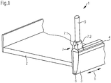
- the Figure 1 shows a section of an embodiment of a catwalk 1 according to the invention in a simplified schematic three-dimensional representation.
- the catwalk 1 for attachment to a machine for the production, processing or processing of a fibrous web, suitable and intended. It comprises a catwalk bottom 2 lying in a horizontal plane, which is connected at least on one boundary side to a catwalk cheek 3 designed as a hollow profile.
- the catwalk cheek 3 extends with its long side in the longitudinal direction 5.
- the hollow profile has a cavity 6.
- the catwalk 1 also comprises at least one railing post 9, to which a handrail (not shown) is attached.
- the catwalk cheek 3 has a cross-sectional profile 4 on its upward-facing side, preferably over the entire length of the catwalk cheek 3, for sliding, form-fitting connection to at least one clamping element 7 having a complementary profile 8.
- the catwalk cheek 3 with the clamping element 7 is preferably arranged on the boundary side of the catwalk floor 2 facing away from the machine, that is to say on the outside.
- at least the catwalk cheek 3 can also be arranged on the inner side of the catwalk floor 2, that is to say on the side facing the machine. In the example shown, only a sheet metal strip is arranged on the inside.
- the catwalk 1 can have several clamping elements 7, each with a railing post 9.
- connection between the catwalk cheek 3 and the at least one clamping element 7 is established by using or designing the cross-sectional profile 4 and the complementary profile 8 as interlocking, complementary profile shapes. It is designed so that the clamping element 7 is mounted displaceably along the catwalk cheek 3 and remains connected in a form-fitting manner.
- the components for example the at least one clamping element 7, can be used flexibly at different locations of the machine, or can be reused in the case of modifications, without new components having to be designed and manufactured.
- the connection between the at least one clamping element 7 and the catwalk cheek 3 can be locked by clamping.
- the at least one clamping element 7 is designed in two parts.
- Both Clamping element parts 7.1, 7.2 are held in position relative to one another by clamping elements 13, such as screws as in this example. With the clamping elements 13, a displaceable or a locked connection between the at least one clamping element 7 and the catwalk cheek 3 can thus be established.
- a lock is useful after adjusting the railing for fixation.
- An adaptation of the railing, for example a change in the distance between the railing posts 9, can be carried out without changing the catwalk cheek 3 and while maintaining the safety function of the railing, since after the clamping element 7 has been released by the clamping elements, the clamping element 7 can be moved and the Positive fit between the cross-sectional profile 4 and the complementary profile 8 is retained.
- the clamping element 7 is arranged above the catwalk cheek 3, that is to say on the upper side.
- the surface assigned to the catwalk floor 2 and the opposite outer surface of the catwalk cheek 3 thus have no protruding holders for the railing posts 9, which could pose a tripping hazard.
- this configuration increases the safety for the staff and, on the other hand, it also promotes cleanliness and keeping the machine clean.
- the two clamping element parts 7.1, 7.2 of the at least one clamping element 7 have positioning elements 11, 12, preferably tongue and groove.
- the assembly of the at least one clamping element 7 on the catwalk cheek 3 is also simplified with regard to the interlocking, complementary profile shapes.
- the at least one clamping element 7 has on the side opposite the complementary profile 8 a receiving opening 10 for a round railing post 9.
- the railing post 9 is fastened in the receiving opening 10 by clamping and by a form fit.
- the clamping element 7 has a continuous threaded hole 14 for a screw provided with a point.
- the tip is pressed onto the railing post 9 and thus, on the one hand, a clamping and, on the other hand, the positive fit. If a screw with a blunt start is used, there is only one clamping. It is also possible to match the dimensions of the receiving opening 10 to the railing post 9 in such a way that it is clamped by the clamping elements 13 when the two clamping element parts 7.1, 7.2 are clamped.
- the catwalk cheek 3 is dimensioned so that it can carry the load of the catwalk floor.
- the cross section is across the length of the catwalk cheek 3 higher than wide. This increases the bending resistance.
- the upper side of the catwalk cheek 3 lies above the catwalk floor. This prevents parts lying on the walkway floor from falling.
- the catwalk cheek 3 is made in one piece.
- the catwalk cheek 3 is made of aluminum.
- FIG. 2 an exemplary cross-sectional shape transverse to the longitudinal direction 5 of a first variant of a one-piece catwalk cheek 3 is shown in a simplified three-dimensional illustration.
- the catwalk cheek 3 has a plurality of cavities 6 which extend in the longitudinal direction 5. The cavities are separated from one another by webs. The bars increase the stability of the extruded profile.
- the cross-sectional profile for receiving the clamping element is attached to the upper side of the catwalk cheek 3.
- the shape of the cross-sectional profile is designed like a T-profile and the matching shape of the complementary profile of the clamping element 7 is then designed like a C-profile, as in FIG Figures 4 and 5 shown.
- the Figure 3 shows a section of an exemplary second embodiment of a catwalk cheek in a simplified three-dimensional representation. It differs from the embodiments according to Figure 1 to 3 in that an information element 17 for displaying text and / or images is integrated into the catwalk cheek 3.
- the information element 17 can be LCD / LED displays.
- This embodiment can also be used to inform the machine personnel, for example, about the operating status of the machine, about due service or about the security situation.
- FIG. 4 a section of an exemplary third embodiment of a catwalk cheek 3 is shown in a simplified three-dimensional illustration.
- supply lines 15 and / or data lines 15 are passed through the cavity 6.
- the catwalk cheek 3 has, on the side facing away from the catwalk floor 2, three openings 16 and / or windows 16 for emitting light signals.
- This can be colored LED light. The colors can be assigned meanings. This can be used to inform the machine staff, for example To inform about the operating status of the machine, about due service or about the security situation.
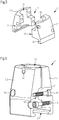
- the Figure 5 shows a first embodiment of a two-part clamping element 7 in a simplified three-dimensional illustration.
- a complementary profile 8 is attached, which is designed like a C-profile. It has positioning elements 11, 12 which enable the two clamping element parts 7.1, 7.2 to be positioned in the vertical direction. This is made possible by complementary projections and recesses on the joining surfaces of the two clamping element parts 7.1, 7.2.
- the illustrated second exemplary embodiment of a two-part clamping element in a simplified three-dimensional representation differs from the first exemplary embodiment in FIG Figure 5 on the one hand in the execution of the positioning elements 11, 12 and on the other hand in the threaded bore 14 for receiving a screw for clamping the railing post 9 located in the receiving opening 10.
- the first clamping element part 7.1 has a spring as the positioning element 11, while the second clamping element part 7.2 has a groove.
- the clamping elements 13 designed as screws are shown in the sectioned illustration.
Landscapes
- Bridges Or Land Bridges (AREA)
- Escalators And Moving Walkways (AREA)
Abstract
Description
- Die Erfindung betrifft einen Laufsteg zum Anbau an eine Maschine, insbesondere zum Anbau an eine Maschine zur Herstellung, Verarbeitung oder Bearbeitung einer Faserstoffbahn, umfassend einen Laufstegboden, der mindestens an einer Begrenzungsseite mit einer, vorzugsweise als Hohlprofil ausgeführten, Laufstegwange verbunden ist, sowie mindestens zwei mit der Laufstegwange verbundene Geländerpfosten, an welchen ein Handlauf befestigt ist.
- Laufstege dieser Art sind bekannt. Das Dokument
DE 20 2012 104986 U1 offenbart einen Laufsteg für eine Faserbahnmaschine mit einer Laufebene und zwei Stützträgerteilen, welche seitlich an der Laufebene angeordnet und zueinander beabstandet sind, so dass ein Spalt zur Aufnahme der Laufebene ausgebildet wird. Das obere Stützträgerteil ist zweiteilig ausgeführt und besteht aus zwei Hälften, zwischen denen Geländerpaneelen zur Ausbildung eines Geländers geklemmt werden. - Solche bekannten Ausführungen aufwändig, wenig flexibel und müssen für jeden Einsatzort in der Faserbahnmaschine dimensioniert und konstruiert werden. Dies bedeutet eine große Teilevielfalt für große Maschinen mit vielen Laufstegen.
- Die Aufgabe der Erfindung ist es daher einen kostengünstigen und sicheren Laufsteg anzugeben, der im Wesentlichen modular aufgebaut ist und dessen Komponenten zumindest teilweise flexibel einsetzbar, und angeordnet werden können.
- Die Aufgabe wird durch Merkmale des Anspruches 1 gelöst. Es wird ein Laufsteg zum Anbau an eine Maschine, insbesondere zum Anbau an eine Maschine zur Herstellung, Verarbeitung oder Bearbeitung einer Faserstoffbahn, vorgeschlagen, umfassend einen Laufstegboden, der mindestens an einer Begrenzungsseite mit einer, vorzugsweise als Hohlprofil ausgeführten, Laufstegwange verbunden ist, sowie mindestens einen Geländerpfosten, an welchem ein Handlauf befestigt ist. Die Erfindung zeichnet sich dadurch aus, dass die Laufstegwange an ihrer nach oben weisenden Seite ein, vorzugsweise über die gesamte Länge in Längsrichtung der Laufstegwange verlaufendes, Querschnittsprofil zum verschiebbaren, formschlüssigen Verbinden mit mindestens einem, ein komplementäres Profil aufweisenden Klemmelement, aufweist.
- Die Laufstegwange mit dem Klemmelement wird bevorzugt an der der Maschine abgewandten Begrenzungsseite des Laufstegbodens, das heißt an der Außenseite, angeordnet. Für bestimmte Anwendungsfälle kann zumindest die Laufstegwange jedoch auch an der inneren Seite des Laufstegbodens angeordnet sein.
- Die Verbindung zwischen der Laufstegwange und dem mindestens einen Klemmelement wird durch die Anwendung von ineinandergreifenden, komplementären Profilformen hergestellt. Sie ist so ausgeführt, dass das Klemmelement entlang der Laufstegwange verschiebbar gelagert ist und dabei formschlüssig verbunden bleibt. Dadurch können die Komponenten, beispielsweise das mindestens eine Klemmelement, flexibel an verschiedenen Einsatzorten der Maschine eingesetzt werden, oder bei Umbauten wiederverwendet werden, ohne dass neue Komponenten konstruiert und hergestellt werden müssen oder ohne dass mechanische Bearbeitungen, wie beispielsweise Bohren, Gewindeschneiden, an den Komponenten notwendig werden. Eine Anpassung des Geländers, beispielsweise des Abstandes von Geländerpfosten, kann ohne Veränderung an der Laufstegwange und unter Beibehaltung der Sicherheitsfunktion des Geländers durchgeführt werden.
- Ein weiterer Vorteil ist die Anordnung der Klemmelemente oberhalb der Laufstegwange. Die dem Laufstegboden zugeordnete Fläche und die gegenüberliegende Außenfläche der Laufstegwange weisen somit keine hervorstehenden Halterungen für die Geländerpfosten auf. Dies erhöht einerseits die Sicherheit für das Personal und begünstigt zum anderen die Sauberkeit und die Sauberhaltung der Maschine.
- In einer vorteilhaften praktischen Ausführung ist die Verbindung zwischen dem mindestens einen Klemmelement und der Laufstegwange durch klemmen arretierbar. Dies ist nach einer Anpassung des Geländers zwecks Fixierung sinnvoll.
- In einer bevorzugten Ausführung ist das mindestens eine Klemmelement zweiteilig ausgeführt. Das erste Klemmelementteil und das zweite Klemmelementteil werden durch Spannelemente, wie beispielsweise Schrauben in Position zueinander gehalten. Mit den Spannelementen kann somit eine verschiebbare oder eine arretierte Verbindung zwischen dem mindestens einen Klemmelement und der Laufstegwange hergestellt werden.
- Das erste Klemmelementteil und das zweite Klemmelementteil des mindestens einen Klemmelements können Positionierelemente, vorzugsweise Nut und Feder, aufweisen. Dadurch wird die Montage des mindestens einen Klemmelements auf der Laufstegwange auch in Bezug auf die ineinandergreifenden, komplementären Profilformen vereinfacht.
- In einer bevorzugten praktischen Ausgestaltung weist das mindestens eine Klemmelement auf der dem komplementären Profil gegenüberliegenden Seite eine Aufnahmeöffnung für einen, vorzugsweise runden, Geländerpfosten auf.
- Der Geländerpfosten kann in der Aufnahmeöffnung durch Klemmung und/oder durch einen Formschluss befestigt sein.
- Das mindestens eine Klemmelement kann eine Gewindebohrung für eine mit einer Spitze versehenen Schraube, insbesondere für einen Gewindestift, zur Herstellung des Formschlusses aufweisen.
- In einer weiteren möglichen Ausführungsform kann der Geländerpfosten im Bereich der Schraube eine Nut zur Herstellung eines Formschlusses aufweisen.
- Die Laufstegwange ist vorzugsweise ausgeführt um die Last des Laufstegbodens zu tragen. Die Last des Laufstegbodens setzt sich aus dem Gewicht des Laufstegbodens und dem der zusätzlichen Last bei Benutzung des Laufstegbodens zusammen.
- Es ist somit auch aus statischen Gründen vorteilhaft, wenn der Querschnitt quer zur Länge der Laufstegwange höher als breit ist.
- Es ist aus Sicherheitsgründen auch vorteilhaft, wenn die obere Seite der Laufstegwange über dem Laufstegboden liegt.
- Vorzugsweise weist die Laufstegwange einen Hohlraum zur Aufnahme von Versorgungsleitungen und/oder Datenleitungen auf. Dies kann kostengünstig durch die Verwendung von Hohlraumprofilen erreicht werden.
- In einer möglichen Weiterbildung weist die Laufstegwange auf der dem Laufstegboden abgewandten Seite eine Öffnung und /oder Fenster zur Aussendung von Lichtsignalen auf. Hierbei kann es sich um farbiges LED-Licht handeln. Den Farben können Bedeutungen zugeordnet sein. Dies kann genutzt werde, um das Maschinenpersonal beispielsweise über Betriebszustände der Maschine, über fälligen Service oder über die Sicherheitslage zu informieren.
- Entsprechend kann in die Laufstegwange ein Informationselement zum Wiedergeben von Text und/oder Bildern integriert sein. Beim Informationselement kann es sich um LCD/LED-Displays handeln. Diese Ausführungsform kann ebenfalls genutzt werden, um das Maschinenpersonal beispielsweise über Betriebszustände der Maschine, über fälligen Service oder über die Sicherheitslage zu informieren.
- Ferner kann die Laufstegwange einteilig ausgeführt sein. Dies vereinfacht den Aufbau der Laufstegwange und erhöht die Stabilität.
- In einer möglichen Ausgestaltungsvariante ist die Form des Querschnittsprofils T-profilartig ausgeführt und die Form des komplementären Profils C-profilartig ausgeführt. Das C-profilartige Profil des mindestens einen Klemmelements umgreift also das T-profilartige Querschnittsprofil der Laufstegwange. Wird das Klemmelement auf der Laufstegwange arretiert so werden die Spannelemente angezogen, das heißt zusammengezogen, bis eine Klemmung durch das C-profilartige Profil mit dem T-profilartigen Querschnittsprofil entsteht.
- In einer alternativen Ausführungsform ist die Form des Querschnittsprofils C-profilartig ausgeführt und die Form des komplementären Profils T-profilartig ausgeführt. Das C-profilartige Querschnittsprofil der Laufstegwange umgreift also das T-profilartige Profil des mindestens einen Klemmelements. Wird das Klemmelement auf der Laufstegwange arretiert so werden die Spannelemente des mindestens einen Klemmelements angezogen, das heißt das mindestens eine Klemmelement gespreizt, bis eine Klemmung durch das T-profilartige Profil mit dem C-profilartigen Querschnittsprofil entsteht.
- Die Laufstegwange kann aus Aluminium oder Edelstahl bestehen.
- Weitere Merkmale und Vorteile der Erfindung ergeben sich aus der nachfolgenden Beschreibung bevorzugter Ausführungsbeispiele unter Bezugnahme auf die Zeichnungen.
- Es zeigen
- Figur 1
- einen Ausschnitt einer Ausführungsform eines erfindungsgemäßen Laufsteges in vereinfachter schematischer dreidimensionaler Darstellung;
- Figur 2
- eine beispielhafte Querschnittsform einer ersten Ausführungsvariante einer Laufstegwange in vereinfachter dreidimensionaler Darstellung;
- Figur 3
- einen Abschnitt einer beispielhaften zweiten Ausführungsvariante einer Laufstegwange in vereinfachter dreidimensionaler Darstellung;
- Figur 4
- einen Abschnitt einer beispielhaften dritten Ausführungsvariante einer Laufstegwange in vereinfachter dreidimensionaler Darstellung;
- Figur 5
- ein erstes Ausführungsbeispiel eines zweiteiligen Klemmelements in vereinfachter dreidimensionaler Darstellung;
- Figur 6
- ein zweites Ausführungsbeispiel eines zweiteiligen Klemmelements in vereinfachter dreidimensionaler Darstellung;
- Die
Figur 1 zeigt einen Ausschnitt einer Ausführungsform eines erfindungsgemäßen Laufsteges 1 in vereinfachter schematischer dreidimensionaler Darstellung. Der Laufsteg 1 für den Anbau an eine Maschine zur Herstellung, Verarbeitung oder Bearbeitung einer Faserstoffbahn, geeignet und vorgesehen. Er umfasst einen in einer horizontalen Ebene liegenden Laufstegboden 2, der mindestens an einer Begrenzungsseite mit einer als Hohlprofil ausgeführten Laufstegwange 3 verbunden ist. Die Laufstegwange 3 erstreckt sich mit ihrer Längsseite in Längsrichtung 5. Das Hohlprofil weist einen Hohlraum 6 auf. Es sind jedoch auch mehrere Hohlräume 6 entsprechend der Ausführung in derFigur 2 denkbar. Die Hohlräume 6 erstrecken sich in Längsrichtung 5. Der Laufsteg 1 umfasst auch mindestens einen Geländerpfosten 9, an welchem ein nicht dargestellter Handlauf befestigt ist. Die Laufstegwange 3 weist an ihrer nach oben weisenden Seite ein, vorzugsweise über die gesamte Länge der Laufstegwange 3 verlaufendes, Querschnittsprofil 4 zum verschiebbaren, formschlüssigen Verbinden mit mindestens einem, ein komplementäres Profil 8 aufweisenden Klemmelement 7, auf. Die Laufstegwange 3 mit dem Klemmelement 7 wird bevorzugt an der der Maschine abgewandten Begrenzungsseite des Laufstegbodens 2, das heißt an der Außenseite, angeordnet. Für bestimmte Anwendungsfälle kann zumindest die Laufstegwange 3 jedoch auch an der inneren Seite des Laufstegbodens 2, das heißt an der der Maschine zugewandten Seite angeordnet sein. Im dargestellten Beispiel ist auf der Innenseite lediglich ein Blechstreifen angeordnet. In der Praxis kann der Laufsteg1 mehrere Klemmelemente 7 mit jeweils einem Geländerpfosten 9 aufweisen. - Die Verbindung zwischen der Laufstegwange 3 und dem mindestens einen Klemmelement 7 wird durch die Anwendung bzw. die Ausbildung des Querschnittsprofils 4 und des komplementären Profils 8 als ineinandergreifende, komplementäre Profilformen hergestellt. Sie ist so ausgeführt, dass das Klemmelement 7 entlang der Laufstegwange 3 verschiebbar gelagert ist und dabei formschlüssig verbunden bleibt. Dadurch können die Komponenten, beispielsweise das mindestens eine Klemmelement 7, flexibel an verschiedenen Einsatzorten der Maschine eingesetzt werden, oder bei Umbauten wiederverwendet werden, ohne dass neue Komponenten konstruiert und hergestellt werden müssen. Die Verbindung zwischen dem mindestens einen Klemmelement 7 und der Laufstegwange 3 ist durch Klemmen arretierbar. Hierzu ist das mindestens eine Klemmelement 7 zweiteilig ausgeführt. Beide Klemmelementteile 7.1, 7.2 werden durch Spannelemente 13, wie beispielsweise Schrauben wie in diesem Beispiel, in Position zueinander gehalten. Mit den Spannelementen 13 kann somit eine verschiebbare oder eine arretierte Verbindung zwischen dem mindestens einen Klemmelement 7 und der Laufstegwange 3 hergestellt werden. Eine Arretierung ist nach einer Anpassung des Geländers zur Fixierung sinnvoll. Eine Anpassung des Geländers, beispielsweise eine Veränderung des Abstandes der Geländerpfosten 9, kann ohne Veränderung an der Laufstegwange 3 und unter Beibehaltung der Sicherheitsfunktion des Geländers durchgeführt werden, da nach dem Lösen der Klemmung am Klemmelement 7 durch die Spannelemente das Klemmelement 7 verschiebbar ist und der Formschluss zwischen dem Querschnittsprofil 4 und dem komplementären Profil 8 erhalten bleibt. Das Klemmelement 7 ist oberhalb der Laufstegwange 3, das heißt an der oberen Seite, angeordnet. Die dem Laufstegboden 2 zugeordnete Fläche und die gegenüberliegende Außenfläche der Laufstegwange 3 weisen somit keine hervorstehenden Halterungen für die Geländerpfosten 9, die eine Stolpergefahr sein können, auf. Diese Ausgestaltung erhöht einerseits die Sicherheit für das Personal und begünstigt zum anderen auch die Sauberkeit und die Sauberhaltung der Maschine. Die beiden Klemmelementteile 7.1, 7.2 des mindestens einen Klemmelements 7 weisen Positionierelemente 11, 12, vorzugsweise Nut und Feder, auf. Dadurch wird die Montage des mindestens einen Klemmelements 7 auf der Laufstegwange 3 auch in Bezug auf die ineinandergreifenden, komplementären Profilformen vereinfacht. Das mindestens eine Klemmelement 7 weist auf der dem komplementären Profil 8 gegenüberliegenden Seite eine Aufnahmeöffnung 10 für einen runden, Geländerpfosten 9 auf. Der Geländerpfosten 9 ist in der Aufnahmeöffnung 10 durch Klemmung und durch einen Formschluss befestigt. Dafür besitzt das Klemmelement 7 eine durchgehende Gewindebohrung 14 für eine mit einer Spitze versehenen Schraube. Beim Anziehen der Schraube wird die Spitze auf den Geländerpfosten 9 gedrückt und somit einerseits eine Klemmung und andererseits der Formschluss hergestellt. Wird eine Schraube mit einem stumpfen Anfang verwendet entsteht nur eine Klemmung. Es ist auch möglich, die Maße der Aufnahmeöffnung 10 so auf den Geländerpfosten 9 abzustimmen, dass dieser beim Spannen der beiden Klemmelementteile 7.1, 7.2 durch die Spannelemente 13 geklemmt wird. Die Laufstegwange 3 ist so dimensioniert, dass sie die Last des Laufstegbodens tragen kann. Aus statischen Gründen ist daher der Querschnitt quer zur Länge der Laufstegwange 3 höher als breit. Dadurch wird der Biegewiderstand erhöht. Aus Sicherheitsgründen liegt die obere Seite der Laufstegwange 3 über dem Laufstegboden. Dadurch wird das Herabfallen von Teilen, die auf dem Laufstegboden liegen, verhindert. Die Laufstegwange 3 ist einteilig ausgeführt. Die Laufstegwange 3 besteht aus Aluminium.
- In der
Figur 2 ist eine beispielhafte Querschnittsform quer zur Längsrichtung 5 einer ersten Ausführungsvariante einer einteiligen Laufstegwange 3 in vereinfachter dreidimensionaler Darstellung gezeigt. Die Laufstegwange 3 weist mehrere Hohlräume 6 auf, die sich in Längsrichtung 5 erstrecken. Die Hohlräume sind durch Stege voneinander getrennt. Die Stege erhöhen die Stabilität des stranggepressten Profils. Auf der oberen Seite der Laufstegwange 3 ist das Querschnittsprofil zur Aufnahme des Klemmelements angebracht. Die Form des Querschnittsprofils ist T-profilartig ausgeführt und die passende Form des komplementären Profils des Klemmelements 7 ist dann C-profilartig ausgeführt, wie in denFiguren 4 und5 dargestellt. - Die
Figur 3 zeigt einen Abschnitt einer beispielhaften zweiten Ausführungsvariante einer Laufstegwange in vereinfachter dreidimensionaler Darstellung. Sie unterscheidet sich von den Ausführungsformen nachFigur 1 bis 3 dadurch, dass in die Laufstegwange 3 ein Informationselement 17 zum Wiedergeben von Text und/oder Bildern integriert ist. Beim Informationselement 17 kann es sich um LCD/LED-Displays handeln. Diese Ausführungsform kann ebenfalls genutzt werden, um das Maschinenpersonal beispielsweise über Betriebszustände der Maschine, über fälligen Service oder über die Sicherheitslage zu informieren. - In der
Figur 4 ist einen Abschnitt einer beispielhaften dritten Ausführungsvariante einer Laufstegwange 3 in vereinfachter dreidimensionaler Darstellung gezeigt. In dieser Ausführungsvariante sind durch den Hohlraum 6 Versorgungsleitungen 15 und/oder Datenleitungen 15 geführt. Zudem weist die Laufstegwange 3 auf der dem Laufstegboden 2 abgewandten Seite drei Öffnungen 16 und /oder Fenster 16 zur Aussendung von Lichtsignalen auf. Hierbei kann es sich um farbiges LED-Licht handeln. Den Farben können Bedeutungen zugeordnet sein. Dies kann genutzt werden, um das Maschinenpersonal beispielsweise über Betriebszustände der Maschine, über fälligen Service oder über die Sicherheitslage zu informieren. - Die
Figur 5 zeigt ein erstes Ausführungsbeispiel eines zweiteiligen Klemmelements 7 in vereinfachter dreidimensionaler Darstellung. An der Unterseite des Klemmelements 7 ist ein komplementäres Profil 8 angebracht, das C-profilartig ausgeführt ist. Es weist Positionierelemente 11, 12 auf, welche eine Positionierung der beide Klemmelementteile 7.1, 7.2 in vertikaler Richtung ermöglichen. Dies wird durch komplementäre Vor- und Rücksprünge an den Fügeflächen der beiden Klemmelementteile 7.1, 7.2 ermöglicht. - Das in der
Figur 6 dargestellte zweite Ausführungsbeispiel eines zweiteiligen Klemmelements in vereinfachter dreidimensionaler Darstellung unterscheidet sich vom ersten Ausführungsbeispiel inFigur 5 zum einen in der Ausführung der Positionierelemente 11, 12 und zum anderen in der Gewindebohrung 14 zur Aufnahme einer Schraube zum Klemmen des sich in der Aufnahmeöffnung 10 befindenden Geländerpfostens 9. Das erste Klemmelementteil 7.1 weist als Positionierelement 11 eine Feder auf, während das zweite Klemmelementteil 7.2 eine Nut aufweist. Zudem sind in der geschnittenen Darstellung die als Schrauben ausgeführten Spannelemente 13 gezeigt. - Korrespondierende Elemente der Ausführungsbeispiele in den Figuren sind mit gleichen Bezugszeichen versehen. Die Funktionen solcher Elemente in den einzelnen Figuren entsprechen einander, sofern nichts anderes beschrieben ist und es nicht zu Widersprüchen führt. Auf eine wiederholte Beschreibung wird daher verzichtet. Es wird auch darauf hingewiesen, dass die sich unterscheidenden Merkmale der gezeigten Ausführungsbeispiele gegeneinander ausgetauscht und miteinander kombiniert werden können. Die Erfindung ist daher nicht auf die gezeigten Merkmalskombinationen der gezeigten Ausführungsbeispiele beschränkt.
-
- 1
- Laufsteg
- 2
- Laufstegboden
- 3
- Laufstegwange
- 4
- Querschnittsprofil
- 5
- Längsrichtung
- 6
- Hohlraum
- 7
- Klemmelement
- 7.1
- erstes Klemmelementteil
- 7.2
- zweites Klemmelementteil
- 8
- Komplementäres Profil
- 9
- Geländerpfosten
- 10
- Aufnahmeöffnung
- 11
- Positionierelement
- 12
- Positionierelement
- 13
- Spannelemente
- 14
- Gewindebohrung
- 15
- Versorgungsleitungen, Datenleitungen
- 16
- Öffnung
- 17
- Informationselement
Claims (15)
- Laufsteg (1) zum Anbau an eine Maschine, insbesondere zum Anbau an eine Maschine zur Herstellung, Verarbeitung oder Bearbeitung einer Faserstoffbahn, umfassend einen Laufstegboden (2), der mindestens an einer Begrenzungsseite mit einer, vorzugsweise als Hohlprofil ausgeführten, Laufstegwange (3) verbunden ist, sowie mindestens einen Geländerpfosten (9), an welchem ein Handlauf befestigt ist,
dadurch gekennzeichnet, dass
die Laufstegwange (3) an ihrer nach oben weisenden Seite ein, vorzugsweise über die gesamte Länge in Längsrichtung (5) der Laufstegwange (3) verlaufendes, Querschnittsprofil (4) zum verschiebbaren, formschlüssigen Verbinden mit mindestens einem, ein komplementäres Profil (8) aufweisenden Klemmelement (7), aufweist. - Laufsteg nach Anspruch 1,
dadurch gekennzeichnet, dass
die Verbindung zwischen dem mindestens einen Klemmelement 7 und der Laufstegwange 3 durch klemmen arretierbar ist. - Laufsteg nach Anspruch 1 oder 2,
dadurch gekennzeichnet, dass
das mindestens eine Klemmelement 7 zweiteilig ausgeführt ist. - Laufsteg nach Anspruch 3,
dadurch gekennzeichnet, dass
das erste Klemmelementteil 7.1 und das zweite Klemmelementteil 7.2 des mindestens einen Klemmelements 7 Positionierelemente (11, 12) vorzugsweise Nut (11) und Feder (12), aufweisen. - Laufsteg nach einem der vorhergehenden Ansprüche,
dadurch gekennzeichnet, dass
das mindestens eine Klemmelement (7) auf der dem komplementären Profil (8) gegenüberliegenden Seite eine Aufnahmeöffnung (10) für einen, vorzugsweise runden, Geländerpfosten (9) aufweist. - Laufsteg nach Anspruch 4,
dadurch gekennzeichnet, dass
der Geländerpfosten (9) in der Aufnahmeöffnung (10) durch Klemmung oder durch einen Formschluss befestigt ist. - Laufsteg nach einem der vorhergehenden Ansprüche,
dadurch gekennzeichnet, dass
das mindestens eine Klemmelement 7 eine Gewindebohrung (14) für eine Schraube, insbesondere für eine Madenschraube, zur Herstellung des Formschlusses aufweist. - Laufsteg nach einem der vorhergehenden Ansprüche,
dadurch gekennzeichnet, dass
die Laufstegwange (3) so ausgeführt ist um die Last des Laufstegbodens (2) zu tragen. - Laufsteg nach einem der vorhergehenden Ansprüche,
dadurch gekennzeichnet, dass
die Laufstegwange (3) einen Hohlraum (6) zur Aufnahme von Versorgungsleitungen (15) und/oder Datenleitungen (15) aufweist - Laufsteg nach einem der vorhergehenden Ansprüche,
dadurch gekennzeichnet, dass
die Laufstegwange (3) auf der dem Laufstegboden (2) abgewandten Seite eine Öffnung (16) und /oder Fenster (16) zur Aussendung von Lichtsignalen aufweist. - Laufsteg nach einem der vorhergehenden Ansprüche,
dadurch gekennzeichnet, dass
in die Laufstegwange (3) ein Informationselement (17) zum Wiedergeben von Text und/oder Bilder integriert ist. - Laufsteg nach einem der vorhergehenden Ansprüche,
dadurch gekennzeichnet, dass
die Laufstegwange (3) einteilig ausgeführt ist - Laufsteg nach einem der vorhergehenden Ansprüche,
dadurch gekennzeichnet, dass
das die Form des Querschnittsprofils (4) T-profilartig ist und die Form des komplementären Profils (8) C-profilartig ist. - Laufsteg nach einem der vorhergehenden Ansprüche 1 bis 12,
dadurch gekennzeichnet, dass
das die Form des Querschnittsprofils (4) C-profilartig ist und die Form des komplementären Profils (8) T-profilartig ist. - Vorrichtung nach einem der vorhergehenden Ansprüche,
dadurch gekennzeichnet, dass
die Laufstegwange (3) aus Aluminium oder Edelstahl besteht.
Applications Claiming Priority (1)
| Application Number | Priority Date | Filing Date | Title |
|---|---|---|---|
| DE102019110932.9A DE102019110932A1 (de) | 2019-04-29 | 2019-04-29 | Laufsteg |
Publications (3)
| Publication Number | Publication Date |
|---|---|
| EP3733996A1 true EP3733996A1 (de) | 2020-11-04 |
| EP3733996C0 EP3733996C0 (de) | 2024-05-15 |
| EP3733996B1 EP3733996B1 (de) | 2024-05-15 |
Family
ID=69740206
Family Applications (1)
| Application Number | Title | Priority Date | Filing Date |
|---|---|---|---|
| EP20159488.4A Active EP3733996B1 (de) | 2019-04-29 | 2020-02-26 | Laufsteg |
Country Status (3)
| Country | Link |
|---|---|
| EP (1) | EP3733996B1 (de) |
| CN (1) | CN111851116B (de) |
| DE (1) | DE102019110932A1 (de) |
Citations (6)
| Publication number | Priority date | Publication date | Assignee | Title |
|---|---|---|---|---|
| US1762659A (en) * | 1927-06-04 | 1930-06-10 | Steel Scaffolding Company | Scaffold bracket |
| EP0493325A1 (de) * | 1990-12-20 | 1992-07-01 | Josef Rothmund, Jr. | Befestigungsanordnung für einen Geländerpfosten |
| EP2361336A1 (de) * | 2008-10-24 | 2011-08-31 | Metso Paper, Inc. | Schienenpfosten, schienenwerk und fussweganordnung für eine faservliesmaschine |
| GB2480549A (en) * | 2010-05-20 | 2011-11-23 | Simcol Holdings Ltd | Clamping arrangement |
| DE202012104986U1 (de) | 2012-01-03 | 2013-01-14 | Metso Paper, Inc. | Laufsteg für eine Faserbahnmaschine und Stützträgerkonstruktion für einen Laufsteg |
| KR20180111387A (ko) * | 2017-04-01 | 2018-10-11 | 탁권진 | 안전 토우 보드 |
Family Cites Families (2)
| Publication number | Priority date | Publication date | Assignee | Title |
|---|---|---|---|---|
| DE20207902U1 (de) * | 2002-05-22 | 2002-08-22 | Krämer GmbH, 72555 Metzingen | Laufsteg |
| FI121474B (fi) * | 2009-04-30 | 2010-11-30 | Metso Paper Inc | Kuiturainakoneen hoitotasojärjestely ja kuiturainakone |
-
2019
- 2019-04-29 DE DE102019110932.9A patent/DE102019110932A1/de not_active Withdrawn
-
2020
- 2020-02-26 EP EP20159488.4A patent/EP3733996B1/de active Active
- 2020-04-15 CN CN202010294062.3A patent/CN111851116B/zh active Active
Patent Citations (6)
| Publication number | Priority date | Publication date | Assignee | Title |
|---|---|---|---|---|
| US1762659A (en) * | 1927-06-04 | 1930-06-10 | Steel Scaffolding Company | Scaffold bracket |
| EP0493325A1 (de) * | 1990-12-20 | 1992-07-01 | Josef Rothmund, Jr. | Befestigungsanordnung für einen Geländerpfosten |
| EP2361336A1 (de) * | 2008-10-24 | 2011-08-31 | Metso Paper, Inc. | Schienenpfosten, schienenwerk und fussweganordnung für eine faservliesmaschine |
| GB2480549A (en) * | 2010-05-20 | 2011-11-23 | Simcol Holdings Ltd | Clamping arrangement |
| DE202012104986U1 (de) | 2012-01-03 | 2013-01-14 | Metso Paper, Inc. | Laufsteg für eine Faserbahnmaschine und Stützträgerkonstruktion für einen Laufsteg |
| KR20180111387A (ko) * | 2017-04-01 | 2018-10-11 | 탁권진 | 안전 토우 보드 |
Also Published As
| Publication number | Publication date |
|---|---|
| CN111851116A (zh) | 2020-10-30 |
| DE102019110932A1 (de) | 2020-10-29 |
| CN111851116B (zh) | 2022-10-11 |
| EP3733996C0 (de) | 2024-05-15 |
| EP3733996B1 (de) | 2024-05-15 |
Similar Documents
| Publication | Publication Date | Title |
|---|---|---|
| DE9116213U1 (de) | Profilverbindung, insbesondere für Aluminium-Leichtbau | |
| DE2546833A1 (de) | Vorrichtung zum stirnseitigen anschluss eines strangprofils an einem zumindest an der verbindungsstelle durchlaufenden strangprofil | |
| DE1003937B (de) | Gelaenderkonstruktion, insbesondere fuer Treppen | |
| DE29703481U1 (de) | Universelles Tragegestell zur Montage von Paneelen, insbesondere Solar- und Photovoltaikmodulen | |
| DE10304978A1 (de) | Anhängevorrichtung für ein landwirtschaftliches oder industrielles Arbeitsfahrzeug | |
| DE2828676C2 (de) | Nadelbarre für eine Tuftingmaschine | |
| DE202006007845U1 (de) | Vorrichtung zum Festlegen eines Gegenstandes | |
| DE102006016045B4 (de) | Vorrichtung zur lösbaren Halterung von einem Flächenelement und deren Verwendung | |
| DE2516160B2 (de) | Webeschaft mit am schaftstab verschiebbar und loesbar befestigbarem fuehrungsstueck | |
| WO1992019873A1 (de) | Anordnung für eine lösbare verbindung von flexiblen bahnen oder dergleichen an mit nuten versehenen profilen | |
| EP0976891B1 (de) | Aufbausystem | |
| EP0004374A1 (de) | Vorrichtung zum Verbinden von zwei Profilstäben | |
| DE10150707C1 (de) | Vorrichtung zur Aufnahme eines Lauforgans | |
| EP3733996B1 (de) | Laufsteg | |
| DE2539363C2 (de) | Blendrahmenschenkel | |
| EP0423474B1 (de) | Vorrichtung zum lösbaren Verbinden von zwei Profilstäben | |
| EP1707722A1 (de) | Feststellvorrichtung für Türflügel mit einem Türschliesser | |
| CH634359A5 (de) | Verbindungsstab zwischen dem schaftrahmen einer webmaschine und dem schaftzughebel der sie steuernden fachbildemaschine. | |
| DE2755079C3 (de) | Treibstangenbeschlag für Fenster, Türen oder dergleichen | |
| AT413184B (de) | Vorrichtung für die neigungs-verstellung von schubladen-frontblenden | |
| DE29603402U1 (de) | Rahmenwerk mit Winkel- oder Eckverbindungen von Metallprofilen, insbesondere aus Leichtmetall | |
| DE10228888A1 (de) | Punkthalter für Verbundsicherheitsglasplatte | |
| DE19826246A1 (de) | Teilesatz zum Aufbau einer Konsole sowie Verfahren zum Herstellen einer Konsole und zum Ausstellen einer Maschine | |
| EP3591140A1 (de) | Schwerlastriegel, gerüst, verfahren zur herstellung eines schwerlastriegels, verfahren zur herstellung eines gerüsts | |
| DE9014027U1 (de) | Energieführungskette |
Legal Events
| Date | Code | Title | Description |
|---|---|---|---|
| PUAI | Public reference made under article 153(3) epc to a published international application that has entered the european phase |
Free format text: ORIGINAL CODE: 0009012 |
|
| STAA | Information on the status of an ep patent application or granted ep patent |
Free format text: STATUS: THE APPLICATION HAS BEEN PUBLISHED |
|
| AK | Designated contracting states |
Kind code of ref document: A1 Designated state(s): AL AT BE BG CH CY CZ DE DK EE ES FI FR GB GR HR HU IE IS IT LI LT LU LV MC MK MT NL NO PL PT RO RS SE SI SK SM TR |
|
| AX | Request for extension of the european patent |
Extension state: BA ME |
|
| STAA | Information on the status of an ep patent application or granted ep patent |
Free format text: STATUS: REQUEST FOR EXAMINATION WAS MADE |
|
| 17P | Request for examination filed |
Effective date: 20210504 |
|
| RBV | Designated contracting states (corrected) |
Designated state(s): AL AT BE BG CH CY CZ DE DK EE ES FI FR GB GR HR HU IE IS IT LI LT LU LV MC MK MT NL NO PL PT RO RS SE SI SK SM TR |
|
| STAA | Information on the status of an ep patent application or granted ep patent |
Free format text: STATUS: EXAMINATION IS IN PROGRESS |
|
| 17Q | First examination report despatched |
Effective date: 20220707 |
|
| GRAP | Despatch of communication of intention to grant a patent |
Free format text: ORIGINAL CODE: EPIDOSNIGR1 |
|
| STAA | Information on the status of an ep patent application or granted ep patent |
Free format text: STATUS: GRANT OF PATENT IS INTENDED |
|
| RIC1 | Information provided on ipc code assigned before grant |
Ipc: D21F 7/00 20060101ALN20240115BHEP Ipc: D21G 5/00 20060101ALI20240115BHEP Ipc: E04G 7/00 20060101ALI20240115BHEP Ipc: E04G 5/14 20060101AFI20240115BHEP |
|
| RIC1 | Information provided on ipc code assigned before grant |
Ipc: D21F 7/00 20060101ALN20240123BHEP Ipc: D21G 5/00 20060101ALI20240123BHEP Ipc: E04G 7/00 20060101ALI20240123BHEP Ipc: E04G 5/14 20060101AFI20240123BHEP |
|
| INTG | Intention to grant announced |
Effective date: 20240206 |
|
| GRAS | Grant fee paid |
Free format text: ORIGINAL CODE: EPIDOSNIGR3 |
|
| GRAA | (expected) grant |
Free format text: ORIGINAL CODE: 0009210 |
|
| STAA | Information on the status of an ep patent application or granted ep patent |
Free format text: STATUS: THE PATENT HAS BEEN GRANTED |
|
| AK | Designated contracting states |
Kind code of ref document: B1 Designated state(s): AL AT BE BG CH CY CZ DE DK EE ES FI FR GB GR HR HU IE IS IT LI LT LU LV MC MK MT NL NO PL PT RO RS SE SI SK SM TR |
|
| REG | Reference to a national code |
Ref country code: CH Ref legal event code: EP |
|
| REG | Reference to a national code |
Ref country code: DE Ref legal event code: R096 Ref document number: 502020007975 Country of ref document: DE |
|
| REG | Reference to a national code |
Ref country code: IE Ref legal event code: FG4D Free format text: LANGUAGE OF EP DOCUMENT: GERMAN |
|
| U01 | Request for unitary effect filed |
Effective date: 20240515 |
|
| U07 | Unitary effect registered |
Designated state(s): AT BE BG DE DK EE FI FR IT LT LU LV MT NL PT SE SI Effective date: 20240522 |
|
| PG25 | Lapsed in a contracting state [announced via postgrant information from national office to epo] |
Ref country code: IS Free format text: LAPSE BECAUSE OF FAILURE TO SUBMIT A TRANSLATION OF THE DESCRIPTION OR TO PAY THE FEE WITHIN THE PRESCRIBED TIME-LIMIT Effective date: 20240915 |
|
| PG25 | Lapsed in a contracting state [announced via postgrant information from national office to epo] |
Ref country code: HR Free format text: LAPSE BECAUSE OF FAILURE TO SUBMIT A TRANSLATION OF THE DESCRIPTION OR TO PAY THE FEE WITHIN THE PRESCRIBED TIME-LIMIT Effective date: 20240515 |
|
| PG25 | Lapsed in a contracting state [announced via postgrant information from national office to epo] |
Ref country code: GR Free format text: LAPSE BECAUSE OF FAILURE TO SUBMIT A TRANSLATION OF THE DESCRIPTION OR TO PAY THE FEE WITHIN THE PRESCRIBED TIME-LIMIT Effective date: 20240816 |
|
| PG25 | Lapsed in a contracting state [announced via postgrant information from national office to epo] |
Ref country code: ES Free format text: LAPSE BECAUSE OF FAILURE TO SUBMIT A TRANSLATION OF THE DESCRIPTION OR TO PAY THE FEE WITHIN THE PRESCRIBED TIME-LIMIT Effective date: 20240515 |
|
| PG25 | Lapsed in a contracting state [announced via postgrant information from national office to epo] |
Ref country code: PL Free format text: LAPSE BECAUSE OF FAILURE TO SUBMIT A TRANSLATION OF THE DESCRIPTION OR TO PAY THE FEE WITHIN THE PRESCRIBED TIME-LIMIT Effective date: 20240515 |
|
| PG25 | Lapsed in a contracting state [announced via postgrant information from national office to epo] |
Ref country code: PL Free format text: LAPSE BECAUSE OF FAILURE TO SUBMIT A TRANSLATION OF THE DESCRIPTION OR TO PAY THE FEE WITHIN THE PRESCRIBED TIME-LIMIT Effective date: 20240515 Ref country code: NO Free format text: LAPSE BECAUSE OF FAILURE TO SUBMIT A TRANSLATION OF THE DESCRIPTION OR TO PAY THE FEE WITHIN THE PRESCRIBED TIME-LIMIT Effective date: 20240815 Ref country code: IS Free format text: LAPSE BECAUSE OF FAILURE TO SUBMIT A TRANSLATION OF THE DESCRIPTION OR TO PAY THE FEE WITHIN THE PRESCRIBED TIME-LIMIT Effective date: 20240915 Ref country code: HR Free format text: LAPSE BECAUSE OF FAILURE TO SUBMIT A TRANSLATION OF THE DESCRIPTION OR TO PAY THE FEE WITHIN THE PRESCRIBED TIME-LIMIT Effective date: 20240515 Ref country code: GR Free format text: LAPSE BECAUSE OF FAILURE TO SUBMIT A TRANSLATION OF THE DESCRIPTION OR TO PAY THE FEE WITHIN THE PRESCRIBED TIME-LIMIT Effective date: 20240816 Ref country code: ES Free format text: LAPSE BECAUSE OF FAILURE TO SUBMIT A TRANSLATION OF THE DESCRIPTION OR TO PAY THE FEE WITHIN THE PRESCRIBED TIME-LIMIT Effective date: 20240515 Ref country code: RS Free format text: LAPSE BECAUSE OF FAILURE TO SUBMIT A TRANSLATION OF THE DESCRIPTION OR TO PAY THE FEE WITHIN THE PRESCRIBED TIME-LIMIT Effective date: 20240815 |
|
| PG25 | Lapsed in a contracting state [announced via postgrant information from national office to epo] |
Ref country code: CZ Free format text: LAPSE BECAUSE OF FAILURE TO SUBMIT A TRANSLATION OF THE DESCRIPTION OR TO PAY THE FEE WITHIN THE PRESCRIBED TIME-LIMIT Effective date: 20240515 |
|
| PG25 | Lapsed in a contracting state [announced via postgrant information from national office to epo] |
Ref country code: SK Free format text: LAPSE BECAUSE OF FAILURE TO SUBMIT A TRANSLATION OF THE DESCRIPTION OR TO PAY THE FEE WITHIN THE PRESCRIBED TIME-LIMIT Effective date: 20240515 Ref country code: RO Free format text: LAPSE BECAUSE OF FAILURE TO SUBMIT A TRANSLATION OF THE DESCRIPTION OR TO PAY THE FEE WITHIN THE PRESCRIBED TIME-LIMIT Effective date: 20240515 |
|
| PG25 | Lapsed in a contracting state [announced via postgrant information from national office to epo] |
Ref country code: SM Free format text: LAPSE BECAUSE OF FAILURE TO SUBMIT A TRANSLATION OF THE DESCRIPTION OR TO PAY THE FEE WITHIN THE PRESCRIBED TIME-LIMIT Effective date: 20240515 |
|
| PG25 | Lapsed in a contracting state [announced via postgrant information from national office to epo] |
Ref country code: SM Free format text: LAPSE BECAUSE OF FAILURE TO SUBMIT A TRANSLATION OF THE DESCRIPTION OR TO PAY THE FEE WITHIN THE PRESCRIBED TIME-LIMIT Effective date: 20240515 Ref country code: SK Free format text: LAPSE BECAUSE OF FAILURE TO SUBMIT A TRANSLATION OF THE DESCRIPTION OR TO PAY THE FEE WITHIN THE PRESCRIBED TIME-LIMIT Effective date: 20240515 Ref country code: RO Free format text: LAPSE BECAUSE OF FAILURE TO SUBMIT A TRANSLATION OF THE DESCRIPTION OR TO PAY THE FEE WITHIN THE PRESCRIBED TIME-LIMIT Effective date: 20240515 Ref country code: CZ Free format text: LAPSE BECAUSE OF FAILURE TO SUBMIT A TRANSLATION OF THE DESCRIPTION OR TO PAY THE FEE WITHIN THE PRESCRIBED TIME-LIMIT Effective date: 20240515 |
|
| REG | Reference to a national code |
Ref country code: DE Ref legal event code: R097 Ref document number: 502020007975 Country of ref document: DE |
|
| PLBE | No opposition filed within time limit |
Free format text: ORIGINAL CODE: 0009261 |
|
| STAA | Information on the status of an ep patent application or granted ep patent |
Free format text: STATUS: NO OPPOSITION FILED WITHIN TIME LIMIT |
|
| U20 | Renewal fee for the european patent with unitary effect paid |
Year of fee payment: 6 Effective date: 20250228 |
|
| 26N | No opposition filed |
Effective date: 20250218 |
|
| PG25 | Lapsed in a contracting state [announced via postgrant information from national office to epo] |
Ref country code: MC Free format text: LAPSE BECAUSE OF FAILURE TO SUBMIT A TRANSLATION OF THE DESCRIPTION OR TO PAY THE FEE WITHIN THE PRESCRIBED TIME-LIMIT Effective date: 20240515 |
|
| REG | Reference to a national code |
Ref country code: CH Ref legal event code: PL |
|
| PG25 | Lapsed in a contracting state [announced via postgrant information from national office to epo] |
Ref country code: CH Free format text: LAPSE BECAUSE OF NON-PAYMENT OF DUE FEES Effective date: 20250228 |
|
| GBPC | Gb: european patent ceased through non-payment of renewal fee |
Effective date: 20250226 |
|
| PG25 | Lapsed in a contracting state [announced via postgrant information from national office to epo] |
Ref country code: GB Free format text: LAPSE BECAUSE OF NON-PAYMENT OF DUE FEES Effective date: 20250226 |
|
| PG25 | Lapsed in a contracting state [announced via postgrant information from national office to epo] |
Ref country code: IE Free format text: LAPSE BECAUSE OF NON-PAYMENT OF DUE FEES Effective date: 20250226 |
|
| U20 | Renewal fee for the european patent with unitary effect paid |
Year of fee payment: 7 Effective date: 20260302 |