EP3733121B1 - Branch vessel stent - Google Patents
Branch vessel stent Download PDFInfo
- Publication number
- EP3733121B1 EP3733121B1 EP18893638.9A EP18893638A EP3733121B1 EP 3733121 B1 EP3733121 B1 EP 3733121B1 EP 18893638 A EP18893638 A EP 18893638A EP 3733121 B1 EP3733121 B1 EP 3733121B1
- Authority
- EP
- European Patent Office
- Prior art keywords
- stent
- developing
- branch vessel
- developing portion
- wave
- Prior art date
- Legal status (The legal status is an assumption and is not a legal conclusion. Google has not performed a legal analysis and makes no representation as to the accuracy of the status listed.)
- Active
Links
Images



Classifications
-
- A—HUMAN NECESSITIES
- A61—MEDICAL OR VETERINARY SCIENCE; HYGIENE
- A61F—FILTERS IMPLANTABLE INTO BLOOD VESSELS; PROSTHESES; DEVICES PROVIDING PATENCY TO, OR PREVENTING COLLAPSING OF, TUBULAR STRUCTURES OF THE BODY, e.g. STENTS; ORTHOPAEDIC, NURSING OR CONTRACEPTIVE DEVICES; FOMENTATION; TREATMENT OR PROTECTION OF EYES OR EARS; BANDAGES, DRESSINGS OR ABSORBENT PADS; FIRST-AID KITS
- A61F2/00—Filters implantable into blood vessels; Prostheses, i.e. artificial substitutes or replacements for parts of the body; Appliances for connecting them with the body; Devices providing patency to, or preventing collapsing of, tubular structures of the body, e.g. stents
- A61F2/82—Devices providing patency to, or preventing collapsing of, tubular structures of the body, e.g. stents
- A61F2/852—Two or more distinct overlapping stents
-
- A—HUMAN NECESSITIES
- A61—MEDICAL OR VETERINARY SCIENCE; HYGIENE
- A61F—FILTERS IMPLANTABLE INTO BLOOD VESSELS; PROSTHESES; DEVICES PROVIDING PATENCY TO, OR PREVENTING COLLAPSING OF, TUBULAR STRUCTURES OF THE BODY, e.g. STENTS; ORTHOPAEDIC, NURSING OR CONTRACEPTIVE DEVICES; FOMENTATION; TREATMENT OR PROTECTION OF EYES OR EARS; BANDAGES, DRESSINGS OR ABSORBENT PADS; FIRST-AID KITS
- A61F2/00—Filters implantable into blood vessels; Prostheses, i.e. artificial substitutes or replacements for parts of the body; Appliances for connecting them with the body; Devices providing patency to, or preventing collapsing of, tubular structures of the body, e.g. stents
- A61F2/02—Prostheses implantable into the body
- A61F2/04—Hollow or tubular parts of organs, e.g. bladders, tracheae, bronchi or bile ducts
- A61F2/06—Blood vessels
- A61F2/07—Stent-grafts
-
- A—HUMAN NECESSITIES
- A61—MEDICAL OR VETERINARY SCIENCE; HYGIENE
- A61F—FILTERS IMPLANTABLE INTO BLOOD VESSELS; PROSTHESES; DEVICES PROVIDING PATENCY TO, OR PREVENTING COLLAPSING OF, TUBULAR STRUCTURES OF THE BODY, e.g. STENTS; ORTHOPAEDIC, NURSING OR CONTRACEPTIVE DEVICES; FOMENTATION; TREATMENT OR PROTECTION OF EYES OR EARS; BANDAGES, DRESSINGS OR ABSORBENT PADS; FIRST-AID KITS
- A61F2/00—Filters implantable into blood vessels; Prostheses, i.e. artificial substitutes or replacements for parts of the body; Appliances for connecting them with the body; Devices providing patency to, or preventing collapsing of, tubular structures of the body, e.g. stents
- A61F2/82—Devices providing patency to, or preventing collapsing of, tubular structures of the body, e.g. stents
- A61F2/856—Single tubular stent with a side portal passage
-
- A—HUMAN NECESSITIES
- A61—MEDICAL OR VETERINARY SCIENCE; HYGIENE
- A61F—FILTERS IMPLANTABLE INTO BLOOD VESSELS; PROSTHESES; DEVICES PROVIDING PATENCY TO, OR PREVENTING COLLAPSING OF, TUBULAR STRUCTURES OF THE BODY, e.g. STENTS; ORTHOPAEDIC, NURSING OR CONTRACEPTIVE DEVICES; FOMENTATION; TREATMENT OR PROTECTION OF EYES OR EARS; BANDAGES, DRESSINGS OR ABSORBENT PADS; FIRST-AID KITS
- A61F2/00—Filters implantable into blood vessels; Prostheses, i.e. artificial substitutes or replacements for parts of the body; Appliances for connecting them with the body; Devices providing patency to, or preventing collapsing of, tubular structures of the body, e.g. stents
- A61F2/82—Devices providing patency to, or preventing collapsing of, tubular structures of the body, e.g. stents
- A61F2/86—Stents in a form characterised by the wire-like elements; Stents in the form characterised by a net-like or mesh-like structure
- A61F2/88—Stents in a form characterised by the wire-like elements; Stents in the form characterised by a net-like or mesh-like structure the wire-like elements formed as helical or spiral coils
-
- A—HUMAN NECESSITIES
- A61—MEDICAL OR VETERINARY SCIENCE; HYGIENE
- A61F—FILTERS IMPLANTABLE INTO BLOOD VESSELS; PROSTHESES; DEVICES PROVIDING PATENCY TO, OR PREVENTING COLLAPSING OF, TUBULAR STRUCTURES OF THE BODY, e.g. STENTS; ORTHOPAEDIC, NURSING OR CONTRACEPTIVE DEVICES; FOMENTATION; TREATMENT OR PROTECTION OF EYES OR EARS; BANDAGES, DRESSINGS OR ABSORBENT PADS; FIRST-AID KITS
- A61F2/00—Filters implantable into blood vessels; Prostheses, i.e. artificial substitutes or replacements for parts of the body; Appliances for connecting them with the body; Devices providing patency to, or preventing collapsing of, tubular structures of the body, e.g. stents
- A61F2/82—Devices providing patency to, or preventing collapsing of, tubular structures of the body, e.g. stents
- A61F2/86—Stents in a form characterised by the wire-like elements; Stents in the form characterised by a net-like or mesh-like structure
- A61F2/90—Stents in a form characterised by the wire-like elements; Stents in the form characterised by a net-like or mesh-like structure characterised by a net-like or mesh-like structure
- A61F2/91—Stents in a form characterised by the wire-like elements; Stents in the form characterised by a net-like or mesh-like structure characterised by a net-like or mesh-like structure made from perforated sheets or tubes, e.g. perforated by laser cuts or etched holes
- A61F2/915—Stents in a form characterised by the wire-like elements; Stents in the form characterised by a net-like or mesh-like structure characterised by a net-like or mesh-like structure made from perforated sheets or tubes, e.g. perforated by laser cuts or etched holes with bands having a meander structure, adjacent bands being connected to each other
- A61F2002/9155—Adjacent bands being connected to each other
- A61F2002/91575—Adjacent bands being connected to each other connected peak to trough
-
- A—HUMAN NECESSITIES
- A61—MEDICAL OR VETERINARY SCIENCE; HYGIENE
- A61F—FILTERS IMPLANTABLE INTO BLOOD VESSELS; PROSTHESES; DEVICES PROVIDING PATENCY TO, OR PREVENTING COLLAPSING OF, TUBULAR STRUCTURES OF THE BODY, e.g. STENTS; ORTHOPAEDIC, NURSING OR CONTRACEPTIVE DEVICES; FOMENTATION; TREATMENT OR PROTECTION OF EYES OR EARS; BANDAGES, DRESSINGS OR ABSORBENT PADS; FIRST-AID KITS
- A61F2210/00—Particular material properties of prostheses classified in groups A61F2/00 - A61F2/26 or A61F2/82 or A61F9/00 or A61F11/00 or subgroups thereof
- A61F2210/0076—Particular material properties of prostheses classified in groups A61F2/00 - A61F2/26 or A61F2/82 or A61F9/00 or A61F11/00 or subgroups thereof multilayered, e.g. laminated structures
-
- A—HUMAN NECESSITIES
- A61—MEDICAL OR VETERINARY SCIENCE; HYGIENE
- A61F—FILTERS IMPLANTABLE INTO BLOOD VESSELS; PROSTHESES; DEVICES PROVIDING PATENCY TO, OR PREVENTING COLLAPSING OF, TUBULAR STRUCTURES OF THE BODY, e.g. STENTS; ORTHOPAEDIC, NURSING OR CONTRACEPTIVE DEVICES; FOMENTATION; TREATMENT OR PROTECTION OF EYES OR EARS; BANDAGES, DRESSINGS OR ABSORBENT PADS; FIRST-AID KITS
- A61F2250/00—Special features of prostheses classified in groups A61F2/00 - A61F2/26 or A61F2/82 or A61F9/00 or A61F11/00 or subgroups thereof
- A61F2250/0058—Additional features; Implant or prostheses properties not otherwise provided for
- A61F2250/0096—Markers and sensors for detecting a position or changes of a position of an implant, e.g. RF sensors, ultrasound markers
Definitions
- the embodiments relate to the field of medical apparatuses and instruments, and in particular, to a branch vessel stent.
- vascular occlusion caused by a lesion a vascular stent is usually implanted into the lesion area by balloon dilatation of lumen, so as to achieve the purposes of supporting the blood vessel in regions experiencing vascular occlusion and stenosis, reducing elastic retraction, and reshaping the blood vessel and maintaining the smooth blood flow in the lumen.
- the vascular lesion is treated by a main body stent, which may block the blood flow of the branch vessel, resulting in occlusion or insufficient blood supply to the branch vessel.
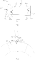
- a diseased blood vessel 10 includes a main vessel 110 and a branch vessel 120.
- the branch vessel 120 stretches out from the main vessel 110, and the branch vessel 120 is connected with the main vessel 110 to form an intersection 111, and a lesion 112 is formed on the vascular wall of the main vessel 110 which is near the intersection 111.
- a conventional method is to implant a main body stent 200 into the main vessel 110 while reconstructing the diseased blood vessel 10, and to perform in-situ fenestration at the intersection 111 where the main body stent 200 is located, and then to introduce a stent for the branch vessel via a branch guide wire, and finally to complete the reconstruction of the branch vessel.
- this method fails to properly account for the relative position of the branch vessel to the main body stent during the in-situ fenestration, so that it is difficult to control the extent to which the branch vessel stent extends into the lumen of the main body stent.
- the branch vessel stent extends too far into the main body stent, it may result in the obstruction of blood flow in the main body stent, and when the branch vessel stent extends for an insufficient distance into the main body stent, it may result in poor anchorage of the branch vessel stent in the main body stent.
- a distal end of the branch vessel stent may also block a port of distal branch vessel.
- EP 3 075 352 A discloses a thoracic aortic covered stent, including a bare stent segment and a covered stent segment, the bare stent segment including a bare wave-shaped ring; the covered stent segment having a lesser curvature side region, a greater curvature side region, and two opposite intermediate regions located between the lesser curvature side region and the greater curvature side region; and the covered stent segment including a first proximal wave-shaped ring, wherein the stent further includes a first connecting member, a first side connecting member and a second side connecting member all connected to the bare wave-shaped ring and the first e proximal wave-shaped ring; the first connecting member is located in the lesser curvature side region, and the first side connecting member and the second side connecting member are located in the two intermediate regions.
- a branch vessel stent includes a stent body and a first developing member; the stent body is provided with a first end and a second end opposite to the first end; the first developing member is located between the first end and the second end as well as close to the first end, and the first developing member includes a first developing portion and a second developing portion.
- the first developing portion extends along a first direction
- the second developing portion extends along a second direction; the first direction obliquely intersects with the second direction, moreover, the length of the first developing portion and the length of the second developing portion in an axial direction of the stent body are both not less than 0.5 mm.
- the distance between the intersections of the first developing portion and the second developing portion on a plane perpendicular to the axial direction of the stent body gradually increases from a position where the distance is the minimum distance to an end that is away from the first end of the first developing portion or the second developing portion.
- the minimum distance between the intersections of the first developing portion and the second developing portion on a plane perpendicular to the axial direction of the stent body is not greater than 2 mm.
- the distance between the intersections of the first developing portion and an end that is close to the first end of the second developing portion on a plane perpendicular to the axial direction of the stent body is the minimum distance.
- the stent body includes a bare stent and a coating film arranged on the bare stent; the first developing portion and the second developing portion are both arranged on the bare stent.
- the bare stent includes a plurality of axially arranged wave rings, the wave rings include a plurality of alternately arranged wave crests and wave troughs, and the adjacent wave crests are connected with the wave troughs through a wave rod; the first developing portion is arranged on the wave rod, and the second developing portion is arranged on a wave rod adjacent to the wave rod of a same wave ring where the first developing portion is located on.
- the length of the first developing portion and the length of the second developing portion are both 1/2 to 2/3 of that of the corresponding wave rods.
- an axial distance from the position where the distance between the intersections of the first developing portion and the second developing portion on the plane perpendicular to the axial direction of the stent body is the minimum distance, to the first end ranges from 5 mm-10 mm.
- the stent body includes a proximal portion, a connecting portion and a distal portion connected in succession; the first end is formed on one end that is away from the connecting portion of the proximal portion; a second end is formed on one end that is away from the connecting portion of the distal portion;
- the cross-sectional area of one end that is close to the proximal portion of the connecting portion is smaller than or equal to that of one end that is close to the distal portion of the connecting portion; and an included angle which ranges from 0-30° is formed between the axial direction and a connecting line between the end that is close to the proximal portion of the connecting portion and the end that is close to the distal portion of the connecting portion; and the first developing member is arranged on the proximal portion.
- One of the embodiments further includes a second developing member and a third developing member; the second developing member is arranged on the first end, and the developing member is arranged on the second end.
- One of the embodiments further includes a skirt-sided stent surrounding the stent body, and the skirt-sided stent is connected with the stent body and extends towards the first end; and one end that is away from the first end of the first developing portion and one end that is away from the first end of the second developing portion are located at a joint portion of the skirt-sided stent and the stent body.
- the skirt-sided stent includes a flexible section and a folding section connected with the flexible section; and the flexible section is connected with the stent body; the distance from one end that is away from the first end of the first developing portion or the second developing portion, to the position where the distance between the intersections of the first developing portion and the second developing portion on the plane perpendicular to the axial direction of the stent body is the minimum distance, is equal to the length of a contour line of the flexible section.
- a first developing member is arranged between a first end and a second end of the above branch vessel stent to conveniently observe the condition of the center of the branch vessel stent, which achieves the identification of any distortion and folding of the branch vessel stent during the release process.
- the distance between the intersections of the first developing portion and the second developing portion on a plane perpendicular to the axial direction of the stent body gradually increases from a position where the distance is the minimum distance to an end that is away from a first end of the first developing portion or the second developing portion.
- the configuration may prevent developing members of the branch vessel stent from being tangled by the developing of wires in the stent body, moreover, it is beneficial to observe and pre-judge the relative position of the branch vessel stent in the main body stent while pulling the branch vessel stent.
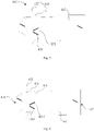
- a branch vessel stent 300 of an embodiment includes a stent body 310 and a developing assembly 320; the developing assembly 320 is arranged on the stent body 310, and the stent body 310 is provided with a first end 316 and a second end 317 opposite to the first end.
- the stent body 310 includes a bare stent and a coating film 315 arranged on the bare stent.
- the bare stent includes a plurality of axially arranged wave rings 312.
- the wave ring 312 includes a plurality of alternately arranged wave crests and wave troughs, and adjacent wave crests and wave troughs are connected by a wave rod.
- an included angle formed by extension lines of adjacent two wave rods ranges from 30°-120°.
- the stent body 310 is formed with a proximal portion 3101, a connecting portion 3102, and a distal portion 3103 connected successively.
- a first end 316 is formed on an end that is opposite from the connecting portion 3102 of the proximal end 3101, and a second end 317 is formed on an end that is opposite from the connecting portion 3102 of the distal portion 3103.
- a coating film of the first end 316 forms a petal-shaped structure, so that blood passes through the first end conveniently; a coating film of the second end 317 is a flush structure.
- the cross-sectional area of the proximal portion 3101 is less than that of the distal portion 3103.
- the cross-sectional area of one end that is close to the proximal portion 3101 of the connecting portion 3102 is smaller than or equal to that of one end that is close to the distal portion 3103 of the connecting portion 3102; and an included angle which ranges from 0-30° is formed between an axial direction and a connecting line between the end that is close to the proximal portion 3101 of the connecting portion 3102 and the end that is close to the distal portion 3103 of the connecting portion 3102.
- an included angle which ranges from 15°-20° is formed between the axial direction and a connecting line between the end that is close to the proximal portion 3101 of the connecting portion 3102 and the end that is close to the distal portion 3103 of the connecting portion 3102.
- the above structure enables the stent body 310 to form a tapered structure, which may enhance the anchoring force of the distal portion 3103, and meanwhile inhibit the transmission of aortic pulsation to the distal portion 3103 of a branch vessel stent.
- proximal portion 3101, the connecting portion 3102 and the distal portion 3103 are differentiated for illustration only, which is not intended to indicate that the stent body 310 is separated on the connecting boundary; the stent body 310 may be an even integral structure.
- the developing assembly 320 includes a first developing member 321, a second developing member 322, and a third developing member 323.
- the first developing member 321 is located between the first end 316 and the second end 317, and proximate to the first end 316.
- the first developing member 321 is located on the proximal portion 3101.
- the second developing member 322 is arranged at the first end 316 and the third developing member 323 is arranged at the second end 317.
- the second developing member 322 serves to designate an initial end of the branch vessel stent 300.
- the third developing member 323 serves to another initial end of the branch vessel stent 300.
- the developing assembly 320 is disposed on a bare stent of the stent body 310. It can be appreciated that in other embodiments, at least one developing member in the developing assembly 320 may also be formed on the coating film 315.
- the first developing member 321 includes a first developing portion 3211 and a second developing portion 3212; the first development portion 3211 extends in a first direction, and the second developing portion 3212 extends in a second direction, and the first direction obliquely intersects with the second direction; and a length of first developing portion 3211 and a length of the second developing portion 3212 in the axial direction of the stent body 310 are not less than 0.5 mm.
- a distance between the intersections of the first developing portion 3211 and the second developing portion 3212 on a plane perpendicular to the axial direction of the stent body 310 gradually increases from a position where the distance is the minimum distance to an end that is away from the first end of the first developing portion 3211 or the second developing portion 3212.
- the minimum distance between the intersections of the first developing portion 3211 and the second developing portion 3212 on a plane perpendicular to the axial direction of the stent body 310 is not greater than 2 mm.
- a distance between the intersections of one end that is close to the first end 316 of the first developing portion 3211 and the second developing portion 3212 on a plane perpendicular to an axial direction of the stent body 310 is the minimum distance.
- the first developing portion 3211 and the second developing portion 3212 are symmetrical with each other along the axis of stent body 310.
- the position where the distance between the intersections of the first developing portion 3211 and the second developing portion 3212 on the plane perpendicular to the axial direction of the stent body 310 is the minimum distance may be also located at the middle part of the first developing portion 3211 and/or the second developing portion 3212.
- the first developing portion 3211 and the second developing portion 3212 are arranged on the bare stent.
- the first developing portion 3211 is arranged on a wave rod of the wave rings 312, and the second developing portion 3212 is arranged on a wave rod of the wave rings 312 adjacent to the first developing portion 3211.
- the first developing portion 3211 and the second developing portion 3212 are respectively formed by winding developing materials on corresponding wave rods respectively (e.g. tantalum wire, etc.).
- the length of the first developing portion 3211 and the length of the second developing portion 3212 are 1/2 to 2/3 of that of the corresponding wave rods, which is convenient for sheathing.
- the first developing portion 3211 and the second developing portion 3212 extend towards the wave troughs from a position close to the wave crests, and the first developing portion 3211 and the second developing portion 3212 are not connected at wave crests. That is, the first developing portion 3211 and the second developing portion 3212 form a " ⁇ /"-shaped structure with a gap between end points.
- the length of the first developing portion 3211 and the length of the second developing portion 3212 are both in the range of 2-4 mm.
- first developing portion 3211 and the second developing portion 3212 may also be connected with each other, thus forming a V-shaped structure.
- Such a configuration can prevent the branch vessel stent 300 from falling off from the main body stent 200, and may decrease the influence of the branch vessel stent 300 on the blood flow in the main body stent 200.
- the second developing member 322 and the third developing member 323 are also arranged on wave rods of the wave rings.
- the second developing member 322 is disposed on a first wave ring near the first end 316
- the third developing member 323 is disposed on a first wave ring near the second end 317.
- Both the second developing member 322 and the third developing member 323 may be formed by winding developing materials on wave rods.
- both the second developing member 322 and the third developing member 323 are I-shaped structures.
- the length of the second developing member 322 and the length of the third developing member 323 may both be 1/2 to 2/3 of that of the corresponding wave rods.
- the length of the second developing member 322 and the length of the third developing member 323 are both in a range of 2-4 mm.
- the second developing member 322 and the third developing member 323 may be other structures, and the number thereof may be plural.
- the branch vessel stent 300 when used for vascular reconstruction, the main body stent 200 is first completely released at a lesion, and then an in-situ fenestration is conducted to expand to the preset pore diameter via a fenestration instrument at a position where the main body stent 200 is located at an intersection 111 of the branch vessel; and then the branch vessel stent 300 is fed via a lumen of a sheath along a path of the branch guide wire.
- the first end 316 is a front end of the branch vessel stent 300 for moving; the branch vessel stent 300 is implanted until one end close to the first end 316 of the first developing portion 3211 or the second developing portion 3212 completely enters into the main body stent 200, finishing the initial positioning at this time; then it starts to release the branch vessel stent 300 from the lumen of the sheath until one end away from the first end 316 of the first developing portion 3211 or the second developing portion 3212 is just released; afterwards, a release device of the lumen of the sheath is locked, and the lumen of the sheath and the branch vessel stent 300 are pulled to move towards one end away from the main vessel of the branch vessel therein until the first developing portion 3211 and the second developing portion 3212 are flush with the wall of the intersection 111 at the position where the distance between the intersections thereof on the plane perpendicular to the axial direction the stent body 310 is the minimum distance, and the pulling is
- a first developing member 321 is arranged between the first end 316 and the second end 317 of the above branch vessel stent 300, which is convenient for observing the condition of the center of the branch vessel stent 300, and may be used for identifying the distortion and folding of the branch vessel stent 300 during the release process, as well as for positioning a length of the branch vessel stent 300 extending into the main body stent 200; moreover, the distance between the intersections of the first developing portion 3211 and the second developing portion 3212 on a plane perpendicular to the axial direction of the stent body 310 gradually increases from a position where the distance is the minimum distance to an end that is away from the first end of the first developing portion 3211 or the second developing portion 3212.
- first developing portion 3211 and the second developing portion 3212 are moved from the main body stent 200, so as to prevent developing members of the branch vessel stent 300 from being tangled by the developing of wires in the main body stent 200, and through the gradual change of the first developing member 321, it is beneficial to observe and pre-judge the relative position of the branch vessel stent 300 in the main body stent 200 during the pulling process, so as to achieve accurate positioning.
- a branch vessel stent 400 in another embodiment includes a stent body 410, a developing member 420 and a skirt-sided stent 430.
- structures of the stent body 410 and the developing member 420 are substantially the same as those in the previous embodiments, and will not be described in detail herein.
- the skirt-sided stent 430 surrounds the outside the stent body 410, and one end of the skirt-sided stent 430 is connected with the stent body 410, and another end of the skirt-sided stent 430 forms an open end towards the first end 416.
- the skirt-sided stent 430 includes a flexible section 431 and a folding section 432 connected with the flexible section 431.
- the flexible section 431 is connected with the stent body 410 via a connecting belt 434, and the connecting belt 434 is used for connecting and supporting the stent body 410 and the flexible section 431.
- the connecting belt 434 may be formed by sewing, winding, cutting or coating.
- one end that is away from the first end 416 of the first developing portion 4211 and the second developing portion 4212 is located at a joint portion of the skirt-sided stent 430 and the stent body 410, i.e., one end that is away from the first end 416 of the first developing portion 4211 and the second developing portion 4212 is flush with the connecting belt 434.
- the folding section 432 is pivotally connected with one end that is away from the connecting belt 434 of the flexible section 431, so that the folding section 432 may be gathered up or folded. Further, the distance from one end that is away from the first end 416 of the first developing portion 4211 or the second developing portion 4212, to the position where the distance between the intersections of the first developing portion 4211 and the second developing portion 4212 on the plane perpendicular to the axial direction of stent body 410 is the minimum distance, is equal to the length of the contour line of the flexible section 431; that is, after insertion into the lumen of the sheath, the first developing portion 4211 and the second developing portion 4212 are flush with one end that is away from the stent body 410 of the flexible section 431 at the position where the distance between the intersections of the first developing portion 4211 and the second developing portion 4212 on the plane perpendicular to the axial direction of stent body 410 is the minimum distance, so as to indicate the initial position of the flexible section
- one end that is away from the connecting band 434 of the flexible section 431 extends toward the direction near the first end 416 to be abutted against the stent body 410, one end that is close to the first end 416 of the flexible section 431 is flush with one end that is close to the first end 416 of the first developing portion 4211 or the second developing portion 4212.
- the diameter of the end that is away from the flexible section 431 of the folding section 432 (i.e., the distance of the projection of the end that is away from the flexible section 431 of the folding section 431 on a plane perpendicular to the stent body 410) is 1.5 to 3 times the diameter of the stent body 410 located therein.
- the diameter of the skirt-sided stent 430 is larger than that of the stent body 410 where the skirt-sided stent 430 is located, and such a design can effectively reduce the risk of internal leakage caused by the cooperation between stents.
- the length of the folding section 432 is less than that of the flexible section 431.
- the flexible section 431 of the branch vessel stent 400 is unfolded and the folding section 432 is turned over towards the direction away from the stent body 410, so as the skirt-sided stent 430 is turned over.
- the branch vessel stent 400 enters the lumen of a sheath in the natural state
- the second end 417 of the stent body 410 first enters the lumen until the connecting belt 434 enters therein; when pushed by the inner wall of the lumen, the flexible section 431 collapses against the stent body 410, and at that moment, the folding section 432 is still in an unfolded state.
- the folding section 432 collapses against the stent body 410, thus achieving the state shown in FIG.7 , thereby completing the sheathing process of the branch vessel stent.
- the main body stent 200 is first completely released at a lesion when the branch vessel stent 400 is used for vascular reconstruction, and in-situ fenestration is conducted to expand to the preset pore diameter via a fenestration instrument at a position where the main body stent 200 is located at an intersection 111 of the branch vessel; then the branch vessel stent 400 is inserted via a lumen of a sheath along the path of branch guide wire.
- the first end 416 is a front end of the stent 400 for the branch vessel; the branch vessel stent 400 is implanted until the first developing portion 4211 and the second developing portion 4212 completely enter into the main body stent 200, finishing the initial positioning at this time; then the branch vessel stent 400 is released from the lumen until one end that is away from the first end 416 of the first developing portion 4211 or the second developing portion 4212, and the skirt-sided stent 430, is released; afterwards, a release device of the lumen is locked, and the lumen and the branch vessel stent 400 are pulled to move towards one end away from the main vessel of the branch vessel therein until the first developing portion 4211 and the second developing portion 4212 are flush with the wall of the intersection 111 at the position where the intersection thereof is on a plane perpendicular to the axial direction the stent body 410, with the pulling stopping at this time. Moreover, the flexible section 431 is squeezed to adhere to the inner wall
Landscapes
- Health & Medical Sciences (AREA)
- Engineering & Computer Science (AREA)
- Biomedical Technology (AREA)
- Heart & Thoracic Surgery (AREA)
- Public Health (AREA)
- Transplantation (AREA)
- Cardiology (AREA)
- Veterinary Medicine (AREA)
- Oral & Maxillofacial Surgery (AREA)
- Vascular Medicine (AREA)
- Life Sciences & Earth Sciences (AREA)
- Animal Behavior & Ethology (AREA)
- General Health & Medical Sciences (AREA)
- Gastroenterology & Hepatology (AREA)
- Pulmonology (AREA)
- Media Introduction/Drainage Providing Device (AREA)
- Prostheses (AREA)
- Dental Tools And Instruments Or Auxiliary Dental Instruments (AREA)
- Materials For Medical Uses (AREA)
Applications Claiming Priority (2)
| Application Number | Priority Date | Filing Date | Title |
|---|---|---|---|
| CN201711488056.6A CN109984864B (zh) | 2017-12-29 | 2017-12-29 | 用于分支血管的支架 |
| PCT/CN2018/121720 WO2019128773A1 (zh) | 2017-12-29 | 2018-12-18 | 用于分支血管的支架 |
Publications (3)
| Publication Number | Publication Date |
|---|---|
| EP3733121A1 EP3733121A1 (en) | 2020-11-04 |
| EP3733121A4 EP3733121A4 (en) | 2021-03-10 |
| EP3733121B1 true EP3733121B1 (en) | 2022-07-06 |
Family
ID=67063105
Family Applications (1)
| Application Number | Title | Priority Date | Filing Date |
|---|---|---|---|
| EP18893638.9A Active EP3733121B1 (en) | 2017-12-29 | 2018-12-18 | Branch vessel stent |
Country Status (6)
| Country | Link |
|---|---|
| US (2) | US11529248B2 (pl) |
| EP (1) | EP3733121B1 (pl) |
| CN (1) | CN109984864B (pl) |
| ES (1) | ES2924079T3 (pl) |
| PL (1) | PL3733121T3 (pl) |
| WO (1) | WO2019128773A1 (pl) |
Families Citing this family (6)
| Publication number | Priority date | Publication date | Assignee | Title |
|---|---|---|---|---|
| CN109984864B (zh) * | 2017-12-29 | 2020-07-17 | 先健科技(深圳)有限公司 | 用于分支血管的支架 |
| CN112826644A (zh) * | 2020-12-31 | 2021-05-25 | 中国人民解放军总医院第一医学中心 | 一种防血栓血管内支架 |
| CN114469442A (zh) * | 2021-12-20 | 2022-05-13 | 杭州创心医学科技有限公司 | 一种分支血管支架 |
| CN116407327B (zh) * | 2021-12-30 | 2025-12-16 | 先健科技(深圳)有限公司 | 一种分支支架 |
| CN116407372A (zh) * | 2021-12-31 | 2023-07-11 | 先健科技(深圳)有限公司 | 管腔支架及管腔支架系统 |
| CN120189274B (zh) * | 2025-05-26 | 2025-08-01 | 北京脉愈医疗科技有限公司 | 一种分支血管支架 |
Family Cites Families (35)
| Publication number | Priority date | Publication date | Assignee | Title |
|---|---|---|---|---|
| US5639278A (en) * | 1993-10-21 | 1997-06-17 | Corvita Corporation | Expandable supportive bifurcated endoluminal grafts |
| US6165213A (en) * | 1994-02-09 | 2000-12-26 | Boston Scientific Technology, Inc. | System and method for assembling an endoluminal prosthesis |
| US6174329B1 (en) * | 1996-08-22 | 2001-01-16 | Advanced Cardiovascular Systems, Inc. | Protective coating for a stent with intermediate radiopaque coating |
| US6599316B2 (en) * | 1996-11-04 | 2003-07-29 | Advanced Stent Technologies, Inc. | Extendible stent apparatus |
| US5741327A (en) * | 1997-05-06 | 1998-04-21 | Global Therapeutics, Inc. | Surgical stent featuring radiopaque markers |
| US5893887A (en) * | 1997-10-14 | 1999-04-13 | Iowa-India Investments Company Limited | Stent for positioning at junction of bifurcated blood vessel and method of making |
| US6699278B2 (en) * | 2000-09-22 | 2004-03-02 | Cordis Corporation | Stent with optimal strength and radiopacity characteristics |
| WO2003061502A1 (en) * | 2000-10-26 | 2003-07-31 | Scimed Life Systems, Inc. | Stent having radiopaque markers and method of fabricating the same |
| US8252040B2 (en) * | 2001-07-20 | 2012-08-28 | Microvention, Inc. | Aneurysm treatment device and method of use |
| GB0322511D0 (en) * | 2003-09-25 | 2003-10-29 | Angiomed Ag | Lining for bodily lumen |
| US7794493B2 (en) * | 2004-06-30 | 2010-09-14 | Cordis Corporation | Magnetic resonance imaging compatibility alloy for implantable medical devices |
| US8562672B2 (en) * | 2004-11-19 | 2013-10-22 | Medtronic, Inc. | Apparatus for treatment of cardiac valves and method of its manufacture |
| US20070191930A1 (en) * | 2006-02-15 | 2007-08-16 | Paul Lucas | Endovascular graft adapter |
| US7988720B2 (en) * | 2006-09-12 | 2011-08-02 | Boston Scientific Scimed, Inc. | Longitudinally flexible expandable stent |
| CN101836911A (zh) * | 2009-03-18 | 2010-09-22 | 微创医疗器械(上海)有限公司 | 侧支型覆膜支架 |
| CN202027751U (zh) * | 2010-05-10 | 2011-11-09 | 谢建 | 一种能使聚合物支架在x射线下清晰可见的显影标记 |
| AU2010210022B1 (en) * | 2010-08-05 | 2011-09-08 | Cook Incorporated | Stent graft having a marker and a reinforcing and marker ring |
| CN102451051B (zh) * | 2010-11-03 | 2015-04-08 | 上海市第六人民医院 | 一种自膨胀节段覆膜非均称网隙支架 |
| US9566149B2 (en) * | 2010-11-16 | 2017-02-14 | W. L. Gore & Associates, Inc. | Devices and methods for in situ fenestration of a stent-graft at the site of a branch vessel |
| WO2013074990A1 (en) * | 2011-11-16 | 2013-05-23 | Bolton Medical, Inc. | Device and method for aortic branched vessel repair |
| CN102697587A (zh) * | 2012-06-25 | 2012-10-03 | 吕文峰 | 一种生物可降解支架及其制备方法 |
| CN104586536B (zh) * | 2013-10-31 | 2017-05-03 | 微创心脉医疗科技(上海)有限公司 | 一种覆膜支架 |
| CN103598929B (zh) * | 2013-11-28 | 2016-04-20 | 先健科技(深圳)有限公司 | 胸主动脉覆膜支架 |
| CN203841857U (zh) * | 2014-04-14 | 2014-09-24 | 上海微特生物技术有限公司 | 一种完全可降解支架 |
| CN104382671B (zh) * | 2014-09-11 | 2016-09-07 | 南京微创医学科技股份有限公司 | 一种可有效防止移位、降低增生的可降解人体支架及制作方法 |
| US10888442B2 (en) * | 2014-11-11 | 2021-01-12 | University of Pittsburgh—of the Commonwealth System of Higher Education | Super elastic, bioabsorbable endovascular devices |
| CN104758090B (zh) * | 2015-04-20 | 2018-09-21 | 上海纽脉医疗科技有限公司 | 一种便于准确定位的介入式人工心脏瓣膜的支架及其制备方法 |
| CN204709090U (zh) * | 2015-06-03 | 2015-10-21 | 李选 | 血管支架 |
| CN106333773B (zh) * | 2015-07-07 | 2018-05-08 | 先健科技(深圳)有限公司 | 血管支架 |
| CA3004821C (en) * | 2015-11-12 | 2023-12-12 | Endospan Ltd. | Stent-grafts systems with skirt |
| CN105496603B (zh) * | 2015-12-30 | 2018-11-06 | 先健科技(深圳)有限公司 | 管腔支架 |
| CN106344209B (zh) * | 2016-10-11 | 2018-11-20 | 有研医疗器械(北京)有限公司 | 一种腹主动脉覆膜支架及其输送装置和使用方法 |
| KR102112820B1 (ko) * | 2017-12-01 | 2020-05-19 | 주식회사 비씨엠 | 미끄럼 방지기능을 향상시킨 스텐트 |
| CN109984864B (zh) * | 2017-12-29 | 2020-07-17 | 先健科技(深圳)有限公司 | 用于分支血管的支架 |
| CN109984863B (zh) * | 2017-12-29 | 2020-04-07 | 先健科技(深圳)有限公司 | 双层血管支架 |
-
2017
- 2017-12-29 CN CN201711488056.6A patent/CN109984864B/zh active Active
-
2018
- 2018-12-18 EP EP18893638.9A patent/EP3733121B1/en active Active
- 2018-12-18 PL PL18893638.9T patent/PL3733121T3/pl unknown
- 2018-12-18 WO PCT/CN2018/121720 patent/WO2019128773A1/zh not_active Ceased
- 2018-12-18 ES ES18893638T patent/ES2924079T3/es active Active
-
2020
- 2020-06-26 US US16/913,764 patent/US11529248B2/en active Active
-
2022
- 2022-11-21 US US17/990,913 patent/US12156823B2/en active Active
Also Published As
| Publication number | Publication date |
|---|---|
| ES2924079T3 (es) | 2022-10-04 |
| EP3733121A1 (en) | 2020-11-04 |
| WO2019128773A1 (zh) | 2019-07-04 |
| CN109984864A (zh) | 2019-07-09 |
| US20200330248A1 (en) | 2020-10-22 |
| US11529248B2 (en) | 2022-12-20 |
| PL3733121T3 (pl) | 2022-11-07 |
| CN109984864B (zh) | 2020-07-17 |
| EP3733121A4 (en) | 2021-03-10 |
| US12156823B2 (en) | 2024-12-03 |
| US20230078930A1 (en) | 2023-03-16 |
Similar Documents
| Publication | Publication Date | Title |
|---|---|---|
| EP3733121B1 (en) | Branch vessel stent | |
| US12569360B2 (en) | Apparatus and method of placement of a graft or graft system | |
| US10478325B2 (en) | Apparatus and method for proximal to distal stent deployment | |
| US6475222B1 (en) | Minimally invasive revascularization apparatus and methods | |
| US9125764B2 (en) | Stent-graft having facing side branch portals | |
| US9237960B2 (en) | Apparatus for curving an implantable medical device in a lumen | |
| US9463104B2 (en) | Vascular graft device placement methods | |
| EP3733133B1 (en) | Double-layer blood vessel stent | |
| JP2015531283A (ja) | デバイス交換中の流れ閉塞の方法とデバイス | |
| US9480561B2 (en) | Apparatus and method for aortic protection and TAVI planar alignment | |
| CN117281658A (zh) | 覆膜支架、支架系统及应用方法 | |
| US20020183769A1 (en) | Medical grafting methods and apparatus | |
| CN111529126A (zh) | 用于将第一细长构件固定至第二细长构件的系统及方法 | |
| US11096810B2 (en) | Preloaded pusher tip for endografts | |
| EP3630010B1 (en) | Branched endoprosthesis with tail for controlled branch deployment | |
| CN117693326A (zh) | 支撑环、主动脉假体和形成方法 |
Legal Events
| Date | Code | Title | Description |
|---|---|---|---|
| STAA | Information on the status of an ep patent application or granted ep patent |
Free format text: STATUS: THE INTERNATIONAL PUBLICATION HAS BEEN MADE |
|
| PUAI | Public reference made under article 153(3) epc to a published international application that has entered the european phase |
Free format text: ORIGINAL CODE: 0009012 |
|
| STAA | Information on the status of an ep patent application or granted ep patent |
Free format text: STATUS: REQUEST FOR EXAMINATION WAS MADE |
|
| 17P | Request for examination filed |
Effective date: 20200709 |
|
| AK | Designated contracting states |
Kind code of ref document: A1 Designated state(s): AL AT BE BG CH CY CZ DE DK EE ES FI FR GB GR HR HU IE IS IT LI LT LU LV MC MK MT NL NO PL PT RO RS SE SI SK SM TR |
|
| AX | Request for extension of the european patent |
Extension state: BA ME |
|
| A4 | Supplementary search report drawn up and despatched |
Effective date: 20210209 |
|
| RIC1 | Information provided on ipc code assigned before grant |
Ipc: A61F 2/07 20130101AFI20210203BHEP Ipc: A61F 2/88 20060101ALN20210203BHEP Ipc: A61F 2/856 20130101ALN20210203BHEP |
|
| DAV | Request for validation of the european patent (deleted) | ||
| DAX | Request for extension of the european patent (deleted) | ||
| GRAP | Despatch of communication of intention to grant a patent |
Free format text: ORIGINAL CODE: EPIDOSNIGR1 |
|
| STAA | Information on the status of an ep patent application or granted ep patent |
Free format text: STATUS: GRANT OF PATENT IS INTENDED |
|
| RIC1 | Information provided on ipc code assigned before grant |
Ipc: A61F 2/856 20130101ALN20220106BHEP Ipc: A61F 2/88 20060101ALN20220106BHEP Ipc: A61F 2/07 20130101AFI20220106BHEP |
|
| INTG | Intention to grant announced |
Effective date: 20220201 |
|
| GRAS | Grant fee paid |
Free format text: ORIGINAL CODE: EPIDOSNIGR3 |
|
| GRAA | (expected) grant |
Free format text: ORIGINAL CODE: 0009210 |
|
| STAA | Information on the status of an ep patent application or granted ep patent |
Free format text: STATUS: THE PATENT HAS BEEN GRANTED |
|
| AK | Designated contracting states |
Kind code of ref document: B1 Designated state(s): AL AT BE BG CH CY CZ DE DK EE ES FI FR GB GR HR HU IE IS IT LI LT LU LV MC MK MT NL NO PL PT RO RS SE SI SK SM TR |
|
| REG | Reference to a national code |
Ref country code: AT Ref legal event code: REF Ref document number: 1502322 Country of ref document: AT Kind code of ref document: T Effective date: 20220715 Ref country code: CH Ref legal event code: EP |
|
| REG | Reference to a national code |
Ref country code: DE Ref legal event code: R096 Ref document number: 602018037765 Country of ref document: DE |
|
| REG | Reference to a national code |
Ref country code: IE Ref legal event code: FG4D |
|
| REG | Reference to a national code |
Ref country code: ES Ref legal event code: FG2A Ref document number: 2924079 Country of ref document: ES Kind code of ref document: T3 Effective date: 20221004 |
|
| REG | Reference to a national code |
Ref country code: LT Ref legal event code: MG9D |
|
| REG | Reference to a national code |
Ref country code: GR Ref legal event code: EP Ref document number: 20220401978 Country of ref document: GR Effective date: 20221109 |
|
| PG25 | Lapsed in a contracting state [announced via postgrant information from national office to epo] |
Ref country code: SE Free format text: LAPSE BECAUSE OF FAILURE TO SUBMIT A TRANSLATION OF THE DESCRIPTION OR TO PAY THE FEE WITHIN THE PRESCRIBED TIME-LIMIT Effective date: 20220706 Ref country code: RS Free format text: LAPSE BECAUSE OF FAILURE TO SUBMIT A TRANSLATION OF THE DESCRIPTION OR TO PAY THE FEE WITHIN THE PRESCRIBED TIME-LIMIT Effective date: 20220706 Ref country code: PT Free format text: LAPSE BECAUSE OF FAILURE TO SUBMIT A TRANSLATION OF THE DESCRIPTION OR TO PAY THE FEE WITHIN THE PRESCRIBED TIME-LIMIT Effective date: 20221107 Ref country code: NO Free format text: LAPSE BECAUSE OF FAILURE TO SUBMIT A TRANSLATION OF THE DESCRIPTION OR TO PAY THE FEE WITHIN THE PRESCRIBED TIME-LIMIT Effective date: 20221006 Ref country code: NL Free format text: LAPSE BECAUSE OF FAILURE TO SUBMIT A TRANSLATION OF THE DESCRIPTION OR TO PAY THE FEE WITHIN THE PRESCRIBED TIME-LIMIT Effective date: 20220706 Ref country code: LV Free format text: LAPSE BECAUSE OF FAILURE TO SUBMIT A TRANSLATION OF THE DESCRIPTION OR TO PAY THE FEE WITHIN THE PRESCRIBED TIME-LIMIT Effective date: 20220706 Ref country code: LT Free format text: LAPSE BECAUSE OF FAILURE TO SUBMIT A TRANSLATION OF THE DESCRIPTION OR TO PAY THE FEE WITHIN THE PRESCRIBED TIME-LIMIT Effective date: 20220706 Ref country code: FI Free format text: LAPSE BECAUSE OF FAILURE TO SUBMIT A TRANSLATION OF THE DESCRIPTION OR TO PAY THE FEE WITHIN THE PRESCRIBED TIME-LIMIT Effective date: 20220706 |
|
| REG | Reference to a national code |
Ref country code: AT Ref legal event code: MK05 Ref document number: 1502322 Country of ref document: AT Kind code of ref document: T Effective date: 20220706 |
|
| PG25 | Lapsed in a contracting state [announced via postgrant information from national office to epo] |
Ref country code: IS Free format text: LAPSE BECAUSE OF FAILURE TO SUBMIT A TRANSLATION OF THE DESCRIPTION OR TO PAY THE FEE WITHIN THE PRESCRIBED TIME-LIMIT Effective date: 20221106 Ref country code: HR Free format text: LAPSE BECAUSE OF FAILURE TO SUBMIT A TRANSLATION OF THE DESCRIPTION OR TO PAY THE FEE WITHIN THE PRESCRIBED TIME-LIMIT Effective date: 20220706 |
|
| REG | Reference to a national code |
Ref country code: DE Ref legal event code: R097 Ref document number: 602018037765 Country of ref document: DE |
|
| PG25 | Lapsed in a contracting state [announced via postgrant information from national office to epo] |
Ref country code: SM Free format text: LAPSE BECAUSE OF FAILURE TO SUBMIT A TRANSLATION OF THE DESCRIPTION OR TO PAY THE FEE WITHIN THE PRESCRIBED TIME-LIMIT Effective date: 20220706 Ref country code: RO Free format text: LAPSE BECAUSE OF FAILURE TO SUBMIT A TRANSLATION OF THE DESCRIPTION OR TO PAY THE FEE WITHIN THE PRESCRIBED TIME-LIMIT Effective date: 20220706 Ref country code: DK Free format text: LAPSE BECAUSE OF FAILURE TO SUBMIT A TRANSLATION OF THE DESCRIPTION OR TO PAY THE FEE WITHIN THE PRESCRIBED TIME-LIMIT Effective date: 20220706 Ref country code: CZ Free format text: LAPSE BECAUSE OF FAILURE TO SUBMIT A TRANSLATION OF THE DESCRIPTION OR TO PAY THE FEE WITHIN THE PRESCRIBED TIME-LIMIT Effective date: 20220706 Ref country code: AT Free format text: LAPSE BECAUSE OF FAILURE TO SUBMIT A TRANSLATION OF THE DESCRIPTION OR TO PAY THE FEE WITHIN THE PRESCRIBED TIME-LIMIT Effective date: 20220706 |
|
| PLBE | No opposition filed within time limit |
Free format text: ORIGINAL CODE: 0009261 |
|
| STAA | Information on the status of an ep patent application or granted ep patent |
Free format text: STATUS: NO OPPOSITION FILED WITHIN TIME LIMIT |
|
| PG25 | Lapsed in a contracting state [announced via postgrant information from national office to epo] |
Ref country code: SK Free format text: LAPSE BECAUSE OF FAILURE TO SUBMIT A TRANSLATION OF THE DESCRIPTION OR TO PAY THE FEE WITHIN THE PRESCRIBED TIME-LIMIT Effective date: 20220706 Ref country code: EE Free format text: LAPSE BECAUSE OF FAILURE TO SUBMIT A TRANSLATION OF THE DESCRIPTION OR TO PAY THE FEE WITHIN THE PRESCRIBED TIME-LIMIT Effective date: 20220706 |
|
| 26N | No opposition filed |
Effective date: 20230411 |
|
| P01 | Opt-out of the competence of the unified patent court (upc) registered |
Effective date: 20230413 |
|
| PG25 | Lapsed in a contracting state [announced via postgrant information from national office to epo] |
Ref country code: AL Free format text: LAPSE BECAUSE OF FAILURE TO SUBMIT A TRANSLATION OF THE DESCRIPTION OR TO PAY THE FEE WITHIN THE PRESCRIBED TIME-LIMIT Effective date: 20220706 |
|
| REG | Reference to a national code |
Ref country code: CH Ref legal event code: PL |
|
| GBPC | Gb: european patent ceased through non-payment of renewal fee |
Effective date: 20221218 |
|
| REG | Reference to a national code |
Ref country code: BE Ref legal event code: MM Effective date: 20221231 |
|
| PG25 | Lapsed in a contracting state [announced via postgrant information from national office to epo] |
Ref country code: SI Free format text: LAPSE BECAUSE OF FAILURE TO SUBMIT A TRANSLATION OF THE DESCRIPTION OR TO PAY THE FEE WITHIN THE PRESCRIBED TIME-LIMIT Effective date: 20220706 Ref country code: LU Free format text: LAPSE BECAUSE OF NON-PAYMENT OF DUE FEES Effective date: 20221218 |
|
| PG25 | Lapsed in a contracting state [announced via postgrant information from national office to epo] |
Ref country code: LI Free format text: LAPSE BECAUSE OF NON-PAYMENT OF DUE FEES Effective date: 20221231 Ref country code: IE Free format text: LAPSE BECAUSE OF NON-PAYMENT OF DUE FEES Effective date: 20221218 Ref country code: GB Free format text: LAPSE BECAUSE OF NON-PAYMENT OF DUE FEES Effective date: 20221218 Ref country code: CH Free format text: LAPSE BECAUSE OF NON-PAYMENT OF DUE FEES Effective date: 20221231 |
|
| PG25 | Lapsed in a contracting state [announced via postgrant information from national office to epo] |
Ref country code: BE Free format text: LAPSE BECAUSE OF NON-PAYMENT OF DUE FEES Effective date: 20221231 |
|
| PG25 | Lapsed in a contracting state [announced via postgrant information from national office to epo] |
Ref country code: CY Free format text: LAPSE BECAUSE OF FAILURE TO SUBMIT A TRANSLATION OF THE DESCRIPTION OR TO PAY THE FEE WITHIN THE PRESCRIBED TIME-LIMIT Effective date: 20220706 |
|
| PG25 | Lapsed in a contracting state [announced via postgrant information from national office to epo] |
Ref country code: MK Free format text: LAPSE BECAUSE OF FAILURE TO SUBMIT A TRANSLATION OF THE DESCRIPTION OR TO PAY THE FEE WITHIN THE PRESCRIBED TIME-LIMIT Effective date: 20220706 Ref country code: HU Free format text: LAPSE BECAUSE OF FAILURE TO SUBMIT A TRANSLATION OF THE DESCRIPTION OR TO PAY THE FEE WITHIN THE PRESCRIBED TIME-LIMIT; INVALID AB INITIO Effective date: 20181218 |
|
| PG25 | Lapsed in a contracting state [announced via postgrant information from national office to epo] |
Ref country code: MC Free format text: LAPSE BECAUSE OF FAILURE TO SUBMIT A TRANSLATION OF THE DESCRIPTION OR TO PAY THE FEE WITHIN THE PRESCRIBED TIME-LIMIT Effective date: 20220706 |
|
| PG25 | Lapsed in a contracting state [announced via postgrant information from national office to epo] |
Ref country code: TR Free format text: LAPSE BECAUSE OF FAILURE TO SUBMIT A TRANSLATION OF THE DESCRIPTION OR TO PAY THE FEE WITHIN THE PRESCRIBED TIME-LIMIT Effective date: 20220706 Ref country code: MC Free format text: LAPSE BECAUSE OF FAILURE TO SUBMIT A TRANSLATION OF THE DESCRIPTION OR TO PAY THE FEE WITHIN THE PRESCRIBED TIME-LIMIT Effective date: 20220706 |
|
| PG25 | Lapsed in a contracting state [announced via postgrant information from national office to epo] |
Ref country code: BG Free format text: LAPSE BECAUSE OF FAILURE TO SUBMIT A TRANSLATION OF THE DESCRIPTION OR TO PAY THE FEE WITHIN THE PRESCRIBED TIME-LIMIT Effective date: 20220706 |
|
| PG25 | Lapsed in a contracting state [announced via postgrant information from national office to epo] |
Ref country code: MT Free format text: LAPSE BECAUSE OF FAILURE TO SUBMIT A TRANSLATION OF THE DESCRIPTION OR TO PAY THE FEE WITHIN THE PRESCRIBED TIME-LIMIT Effective date: 20220706 |
|
| PGFP | Annual fee paid to national office [announced via postgrant information from national office to epo] |
Ref country code: IT Payment date: 20251210 Year of fee payment: 8 |
|
| PGFP | Annual fee paid to national office [announced via postgrant information from national office to epo] |
Ref country code: FR Payment date: 20251230 Year of fee payment: 8 |
|
| PGFP | Annual fee paid to national office [announced via postgrant information from national office to epo] |
Ref country code: GR Payment date: 20251124 Year of fee payment: 8 |
|
| PGFP | Annual fee paid to national office [announced via postgrant information from national office to epo] |
Ref country code: PL Payment date: 20251125 Year of fee payment: 8 |
|
| PGFP | Annual fee paid to national office [announced via postgrant information from national office to epo] |
Ref country code: ES Payment date: 20260112 Year of fee payment: 8 |
|
| PGFP | Annual fee paid to national office [announced via postgrant information from national office to epo] |
Ref country code: DE Payment date: 20251231 Year of fee payment: 8 |