EP3731350B1 - Verbinder und befestigungsverfahren - Google Patents
Verbinder und befestigungsverfahren Download PDFInfo
- Publication number
- EP3731350B1 EP3731350B1 EP18890614.3A EP18890614A EP3731350B1 EP 3731350 B1 EP3731350 B1 EP 3731350B1 EP 18890614 A EP18890614 A EP 18890614A EP 3731350 B1 EP3731350 B1 EP 3731350B1
- Authority
- EP
- European Patent Office
- Prior art keywords
- housing
- cable
- filler
- connector
- accommodating portion
- Prior art date
- Legal status (The legal status is an assumption and is not a legal conclusion. Google has not performed a legal analysis and makes no representation as to the accuracy of the status listed.)
- Active
Links
Images








Classifications
-
- H—ELECTRICITY
- H01—ELECTRIC ELEMENTS
- H01R—ELECTRICALLY-CONDUCTIVE CONNECTIONS; STRUCTURAL ASSOCIATIONS OF A PLURALITY OF MUTUALLY-INSULATED ELECTRICAL CONNECTING ELEMENTS; COUPLING DEVICES; CURRENT COLLECTORS
- H01R4/00—Electrically-conductive connections between two or more conductive members in direct contact, i.e. touching one another; Means for effecting or maintaining such contact; Electrically-conductive connections having two or more spaced connecting locations for conductors and using contact members penetrating insulation
- H01R4/24—Connections using contact members penetrating or cutting insulation or cable strands
- H01R4/2416—Connections using contact members penetrating or cutting insulation or cable strands the contact members having insulation-cutting edges, e.g. of tuning fork type
- H01R4/242—Connections using contact members penetrating or cutting insulation or cable strands the contact members having insulation-cutting edges, e.g. of tuning fork type the contact members being plates having a single slot
- H01R4/2425—Flat plates, e.g. multi-layered flat plates
- H01R4/2429—Flat plates, e.g. multi-layered flat plates mounted in an insulating base
- H01R4/2433—Flat plates, e.g. multi-layered flat plates mounted in an insulating base one part of the base being movable to push the cable into the slot
-
- H—ELECTRICITY
- H01—ELECTRIC ELEMENTS
- H01R—ELECTRICALLY-CONDUCTIVE CONNECTIONS; STRUCTURAL ASSOCIATIONS OF A PLURALITY OF MUTUALLY-INSULATED ELECTRICAL CONNECTING ELEMENTS; COUPLING DEVICES; CURRENT COLLECTORS
- H01R13/00—Details of coupling devices of the kinds covered by groups H01R12/70 or H01R24/00 - H01R33/00
- H01R13/46—Bases; Cases
- H01R13/52—Dustproof, splashproof, drip-proof, waterproof, or flameproof cases
-
- H—ELECTRICITY
- H01—ELECTRIC ELEMENTS
- H01R—ELECTRICALLY-CONDUCTIVE CONNECTIONS; STRUCTURAL ASSOCIATIONS OF A PLURALITY OF MUTUALLY-INSULATED ELECTRICAL CONNECTING ELEMENTS; COUPLING DEVICES; CURRENT COLLECTORS
- H01R4/00—Electrically-conductive connections between two or more conductive members in direct contact, i.e. touching one another; Means for effecting or maintaining such contact; Electrically-conductive connections having two or more spaced connecting locations for conductors and using contact members penetrating insulation
- H01R4/70—Insulation of connections
-
- H—ELECTRICITY
- H01—ELECTRIC ELEMENTS
- H01R—ELECTRICALLY-CONDUCTIVE CONNECTIONS; STRUCTURAL ASSOCIATIONS OF A PLURALITY OF MUTUALLY-INSULATED ELECTRICAL CONNECTING ELEMENTS; COUPLING DEVICES; CURRENT COLLECTORS
- H01R43/00—Apparatus or processes specially adapted for manufacturing, assembling, maintaining, or repairing of line connectors or current collectors or for joining electric conductors
- H01R43/005—Apparatus or processes specially adapted for manufacturing, assembling, maintaining, or repairing of line connectors or current collectors or for joining electric conductors for making dustproof, splashproof, drip-proof, waterproof, or flameproof connection, coupling, or casing
-
- H—ELECTRICITY
- H01—ELECTRIC ELEMENTS
- H01R—ELECTRICALLY-CONDUCTIVE CONNECTIONS; STRUCTURAL ASSOCIATIONS OF A PLURALITY OF MUTUALLY-INSULATED ELECTRICAL CONNECTING ELEMENTS; COUPLING DEVICES; CURRENT COLLECTORS
- H01R43/00—Apparatus or processes specially adapted for manufacturing, assembling, maintaining, or repairing of line connectors or current collectors or for joining electric conductors
- H01R43/01—Apparatus or processes specially adapted for manufacturing, assembling, maintaining, or repairing of line connectors or current collectors or for joining electric conductors for connecting unstripped conductors to contact members having insulation cutting edges
-
- H—ELECTRICITY
- H01—ELECTRIC ELEMENTS
- H01R—ELECTRICALLY-CONDUCTIVE CONNECTIONS; STRUCTURAL ASSOCIATIONS OF A PLURALITY OF MUTUALLY-INSULATED ELECTRICAL CONNECTING ELEMENTS; COUPLING DEVICES; CURRENT COLLECTORS
- H01R4/00—Electrically-conductive connections between two or more conductive members in direct contact, i.e. touching one another; Means for effecting or maintaining such contact; Electrically-conductive connections having two or more spaced connecting locations for conductors and using contact members penetrating insulation
- H01R4/24—Connections using contact members penetrating or cutting insulation or cable strands
- H01R4/2416—Connections using contact members penetrating or cutting insulation or cable strands the contact members having insulation-cutting edges, e.g. of tuning fork type
- H01R4/2445—Connections using contact members penetrating or cutting insulation or cable strands the contact members having insulation-cutting edges, e.g. of tuning fork type the contact members having additional means acting on the insulation or the wire, e.g. additional insulation penetrating means, strain relief means or wire cutting knives
- H01R4/245—Connections using contact members penetrating or cutting insulation or cable strands the contact members having insulation-cutting edges, e.g. of tuning fork type the contact members having additional means acting on the insulation or the wire, e.g. additional insulation penetrating means, strain relief means or wire cutting knives the additional means having two or more slotted flat portions
- H01R4/2456—Connections using contact members penetrating or cutting insulation or cable strands the contact members having insulation-cutting edges, e.g. of tuning fork type the contact members having additional means acting on the insulation or the wire, e.g. additional insulation penetrating means, strain relief means or wire cutting knives the additional means having two or more slotted flat portions in parallel configuration
Definitions
- the present disclosure relates to a connector and an attachment method.
- a connector which holds a plurality of objects by a pair of fitting bodies fitted to each other so that the plurality of objects are electrically connected to each other via a relay contact inside the fitting bodies is conventionally known.
- a connector there is a known technique that protects the connection portion between each object and the relay contact to prevent external foreign matter such as water and dust from entering the connection portion, in a state in which the fitting bodies are fitted to each other.
- PTL 1 discloses a branch connector that can effectively prevent external foreign matter from entering the relay contact side by arranging a main packing and a sub packing inside the fitting bodies.
- US 2005/003708 A1 discloses a waterproof connector including a housing, a number of connecting terminals, a number of press contact blades, rear cover, and a seal member filling layer;
- GB 2330250 A discloses a waterproof connector, wherein, in a connector housing, wires are received in grooves of a main body and encapsulated in an adhesive sealant hardened by ultrasonic vibration;
- JP H10 284170 A discloses a connector having a cover, a housing, and a gelled ultraviolet-ray hardening resin at a site between the cover and the housing.
- one of two objects terminates inside the fitting bodies, and its end is accommodated inside the fitting bodies.
- Protection treatment for the end such as waterproofing, dustproofing, insulation, and rustproofing, is, however, not fully considered. It is desirable to subject the end of the object to sufficient protection treatment in such a connector.
- performing protection treatment in an additional step using insulating tape, a waterproof cap, or the like is not efficient in terms of component count, man-hour, and workability.
- operating accuracy tends to vary and consequently long-term reliability tends to vary.
- protection treatment for an end of an object can be achieved with good workability, and long-term reliability for protection can be improved.
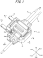
- the connector 10 includes a housing 15, a relay contact 50, and a filler 60 as main structural elements.
- the connector 10 is a branch connector that clamps a core wire of each object 70 such as a cable by the relay contact 50 to bring the objects 70 into conduction with each other.
- the connector 10 electrically branches one object 70 into two objects 70. More specifically, the connector 10 holds two objects 70.
- One of the objects 70 terminates inside the connector 10, and its end is accommodated in the connector 10.
- the other one of the objects 70 extends from the front and back ends of the connector 10 and extends in the front-back direction.
- the housing 15 is a molded component made of an insulating and heat-resistant synthetic resin material.
- the housing 15 includes a pair of fitting bodies that are fittable to each other. More specifically, the housing 15 includes a first housing 20 and a second housing 30 that are fittable to each other.
- the housing 15 includes a connection portion 40 as a connection that connects the first housing 20 and the second housing 30.
- the first housing 20, the second housing 30, and the connection portion 40 are integrally formed in the housing 15.
- the bendable portions 43 are thinner than the first connection portions 41 and the second connection portions 42 at the front and the back.
- the first connection portions 41 and the second connection portions 42 at the front and the back can be valley-folded with the bendable portions 43 extending in the front-back direction as a folding line.
- the connection portion 40 can be bent in a direction in which the first housing 20 and the second housing 30 approach each other.
- the first housing 20, the first connection portions 41, the bendable portions 43, the second connection portions 42, and the second housing 30 have rigidity sufficient to autonomously maintain the expanded state.
- connection portion 40 connects the first housing 20 and the second housing 30 to each other, thus easing the operation of attaching the connector 10 to the object 70 by an assembly operator or the like.
- the filler 60 includes a first filler 61 and a second filler 62 with which the first housing 20 and the second housing 30 are respectively loaded.
- the filler 60 contains any material having cementing properties or sticking properties, such as a UV curing resin, a waterproof gel, or an adhesive. More specifically, in a state in which the first housing 20 and the second housing 30 are fitted to each other, the first filler 61 and the second filler 62 may cement to each other so as to be integral inside the first housing 20 and the second housing 30, or stick to each other to form an interface. In the following description, it is assumed that the filler 60 has cementing properties.
- the filler 60 is made of a UV curing resin that effectively exhibits protection functions such as waterproof function, dustproof function, insulation function, and rustproof function.
- the filler 60 is made of a material containing, as a main ingredient, urethane acrylate, epoxy acrylate, acrylic resin acrylate, polyester acrylate, polybutadiene acrylate, silicone acrylate, amino resin acrylate, urethane vinyl ether, polyester vinyl ether, silicone elastomer, styrene elastomer, polyethylene-polystyrene elastomer, or the like.
- the filler 60 is made of a material containing, as a main ingredient, urethane acrylate that has cementing properties, elasticity, and heat resistance.
- the object 70 includes a first cable 71 and a second cable 72.
- the first cable 71 and the second cable 72 are formed by covering the surfaces of core wires 71a and 72a with sheaths 71b and 72b, respectively.
- the core wires 71a and 72a are each made of a conductive and flexible material such as copper or aluminum.
- the core wires 71a and 72a may be stranded wires or single wires.
- the sheaths 71b and 72b are flexible and insulating tubular sheaths.
- the first cable 71 is a cable that is provided inside a wiring object such as an automobile from the beginning and is connected to a power source of the wiring object.
- the second cable 72 is a cable that is subsequently connected as an addition to electrically branch the first cable 71.
- One end of the second cable 72 is connected to, for example, an electronic device or an electrical device such as a car navigation system.
- FIG. 5 is an enlarged perspective view of the first housing 20.
- the structure of the first housing 20 will be described in detail below, with reference to FIG. 5 .
- the first housing 20 has an outer peripheral wall 20a protruding upward from the outer peripheral edges at the bottom.
- the outer peripheral wall 20a encloses the inside of the first housing 20.
- the first housing 20 has a first recess 20b recessed in an approximately rectangular shape in a top view, on the inner peripheral side of the outer peripheral wall 20a.
- the bottom surface of the first recess 20b is formed by a first facing surface 20c that is an approximately horizontal plane.
- the first housing 20 has a central recess 20d recessed downward in a stepwise manner, in the central part of the first facing surface 20c.
- the bottom surface of the central recess 20d is formed by a central facing surface 20e that is a plane parallel to the first facing surface 20c.
- the first housing 20 has a contact mounting groove 21 formed by the central recess 20d.
- the contact mounting groove 21 has an intermediate projection 21a that is located at the middle in the right-left direction to narrow the front-back width of the contact mounting groove 21 and delimit the contact mounting groove 21 into a pair of right and left parts.
- the intermediate projection 21a is approximately shaped to have a protrusion at its center in a front view.
- the contact mounting groove 21 has protruding portions 21b at four corners on the central facing surface 20e side. The protruding portions 21b narrow the front-back width of the contact mounting groove 21, as with the intermediate projection 21a.
- the contact mounting groove 21 has a pair of positioning protrusions 21c protruding upward from the central facing surface 20e. The positioning protrusions 21c each taper down toward a tip from an approximately cylindrical base.
- the first housing 20 has a pair of first cable mounting grooves 22 and a pair of second cable mounting grooves 23 recessed on the front and back sides of the outer peripheral wall 20a.
- the first cable mounting grooves 22 are located on the front and back sides of the left half part of the contact mounting groove 21, and are approximately on the same axis.
- the second cable mounting grooves 23 are located on the front and back sides of the right half part of the contact mounting groove 21, and are approximately on the same axis.
- the second cable mounting grooves 23 are parallel to the first cable mounting grooves 22.
- the front shape of the first cable mounting grooves 22 and the second cable mounting grooves 23 is approximately a U-shape.
- the first housing 20 has a slope 22a inclined toward the outside in the downward direction from the deepest bottom surface of the first cable mounting groove 22 on the back side.
- the first housing 20 has a pair of slopes 23a inclined toward the outside in the downward direction from the deepest bottom surfaces of the pair of second cable mounting grooves 23.
- the first housing 20 has a platelike lid portion 24a formed at a position below the slope 23a on the front side and extending forward from the front surface of the outer peripheral wall 20a.
- the first housing 20 has a platelike lid portion 24b formed at a position below the slope 22a and the slope 23a on the back side and extending backward from the back surface of the outer peripheral wall 20a.
- the upper surfaces of the lid portions 24a and 24b are at the same height as the lowest parts of the slopes 22a and 23a.
- the first housing 20 has a first wall portion 22b inclined toward the outside in the downward direction from a position slightly away downward from the deepest bottom surface of the first cable mounting groove 22 on the front side.
- the first wall portion 22b is steeper than the slope 22a.
- the lower end of the first wall portion 22b is located lower than the upper surface of the lid portion 24a.
- the first housing 20 has a receiving portion 22c that is continuous with the first wall portion 22b and forms a recess of a predetermined width extending in the forward direction in the lid portion 24a.
- the receiving portion 22c is formed by a groove continuous with the first wall portion 22b and approximately U-shaped in cross section and a slope continuous with the groove and inclined toward the outside in the upward direction.
- the first housing 20 has a pair of first locking portions 25 formed on the right and left sides of the outer peripheral wall 20a and extending in the front-back direction, as illustrated in FIGS. 4 and 5 .
- the first locking portions 25 have elasticity.
- the first locking portions 25 protrude upward from the upper edges of the outer peripheral wall 20a on the front and back sides in a stepwise manner.
- the first locking portions 25 each have an inner surface 25a formed in the up-down direction approximately in a plane shape.
- the first locking portions 25 have first locking protrusions 25b protruding outward from the right and left surfaces of the outer peripheral wall 20a.
- the first locking protrusions 25b extend in the front-back direction.
- the first locking portions 25 each have a slope 25c that forms the outer surface of the first locking protrusion 25b and is inclined toward the outside of the first housing 20 in the downward direction.
- the first locking portions 25 each have a slope 25d that is formed at the upper edge of the inner surface 25a and inclined toward the outside of the first housing 20 in the upward direction.
- the first housing 20 has four notches 25e on the front and back sides of the first locking portions 25.
- the notches 25e are each formed by cutting out the corresponding part of the outer peripheral wall 20a in the protrusion direction of the first locking portion 25, i.e. the up-down direction.
- the notches 25e ease elastic deformation of the first locking portions 25, and improve the fitting between the first housing 20 and the second housing 30.
- the first housing 20 has a pair of pressing portions 26 protruding on the first facing surface 20c between the pair of first cable mounting grooves 22 and the contact mounting groove 21 and between the pair of second cable mounting grooves 23 and the contact mounting groove 21, as illustrated in FIG. 5 .
- the pair of pressing portions 26 are each formed by a pair of ribs arranged side by side in the right-left direction and extending in the front-back direction.
- the first housing 20 has recesses 27 that are each recessed on the inner side of the lower edge of the corresponding first locking portion 25, as illustrated in FIGS. 4 and 5 .
- the recesses 27 are each formed along the lower edge of the corresponding first locking portion 25 in a state of being recessed downward from the first facing surface 20c in a stepwise manner.
- FIG. 6 is an enlarged perspective view of the second housing 30.
- the structure of the second housing 30 will be described in detail below, with reference to FIG. 6 .
- the second housing 30 has an outer peripheral wall 30a protruding upward from the outer peripheral edges at the bottom.
- the outer peripheral wall 30a encloses the inside of the second housing 30.
- the second housing 30 has a second recess 30b recessed in an approximately rectangular shape in a top view, on the inner peripheral side of the outer peripheral wall 30a.
- the bottom surface of the second recess 30b is formed by a second facing surface 30c that is an approximately horizontal plane.
- the second housing 30 has a cable pressing protrusion 31 protruding from the central part of the second facing surface 30c.
- the cable pressing protrusion 31 has a pair of a first pressing groove 31a and a second pressing groove 31b at the right and the left, which are approximately U-shaped in cross section.
- the cable pressing protrusion 31 has a central protrusion 31c and protrusions 31d and 31e located on the left and right sides of the central protrusion 31c.
- the first pressing groove 31a is formed between the central protrusion 31c and the protrusion 31e.
- the second pressing groove 31b is formed between the central protrusion 31c and the protrusion 31d.
- the second housing 30 has cable support arm portions 32a and 32b protruding in the front-back direction from the front and back sides of the outer peripheral wall 30a.
- the second housing 30 has a first cable holding groove 33a recessed in the right half part of the cable support arm portion 32b.
- the first cable holding groove 33a is approximately on the same axis as the first pressing groove 31a.
- the back part of the first cable holding groove 33a is formed by a pair of protrusion pieces 33b separated right and left by a gap.
- the pair of protrusion pieces 33b have a pair of claw portions 33c protruding inward from the lower end of the back end and facing each other.
- the pair of protrusion pieces 33b have a pair of anti-dropout protrusions 33d located inward from the pair of claw portions 33c, protruding in the right-left direction from the upper edge, and facing each other.
- the first cable holding groove 33a has a slope 33e located inward from the pair of anti-dropout protrusions 33d and inclined downward in the inward direction.
- the second housing 30 has a pair of second cable holding grooves 34a recessed in the left half parts of the cable support arm portions 32a and 32b respectively.
- the pair of second cable holding grooves 34a are approximately on the same axis as the second pressing groove 31b.
- the outer part of each second cable holding groove 34a is formed by a pair of protrusion pieces 34b separated right and left by a gap.
- the pair of protrusion pieces 34b have a pair of claw portions 34c protruding inward from the lower end of the outer end and facing each other.
- the pair of protrusion pieces 34b have a pair of anti-dropout protrusions 34d located inward from the pair of claw portions 34c, protruding in the right-left direction from the upper edge, and facing each other.
- Each second cable holding groove 34a has a slope 34e located inward from the pair of anti-dropout protrusions 34d and inclined downward in the inward direction.
- the first cable holding groove 33a and the second cable holding grooves 34a have a depth sufficient to insert and hold the first cable 71 and the second cable 72 for the whole diameter.
- the pairs of protrusion pieces 33b and 34b in particular the protrusion pieces on the right and left outer sides of the cable support arm portions 32a and 32b, elastically flex in the right-left direction.
- the spacing between adjacent protrusion pieces is variable.
- the anti-dropout protrusions 33d and 34d allow the first cable 71 and the second cable 72 to be inserted respectively into the first cable holding groove 33a and the second cable holding grooves 34a.
- the pairs of protrusion pieces 33b and 34b that is, the pairs of anti-dropout protrusions 33d and 34d, flex so as to widen the spacing in the right-left direction.
- the pairs of anti-dropout protrusions 33d and 34d respectively clamp the first cable 71 and the second cable 72.
- the pairs of protrusion pieces 33b and 34b elastically flex so as to narrow the spacing in the right-left direction. Hence, the pairs of protrusion pieces 33b and 34b allow the first cable 71 and the second cable 72 inserted in the first cable holding groove 33a and the second cable holding grooves 34a to move in the cable extending direction, while applying resistance.
- the pairs of protrusion pieces 33b and 34b function as retainers by applying resistance to a force which attempts to separate the first cable 71 and the second cable 72 from the first cable holding groove 33a and the second cable holding grooves 34a, thus preventing the first cable 71 and the second cable 72 from coming out easily.
- This retention function is maintained even when the second housing 30 is turned upside down.
- the pairs of protrusion pieces 33b and 34b allow the first cable 71 and the second cable 72 to separate from the first cable holding groove 33a and the second cable holding grooves 34a when subjected to at least a predetermined external force.
- the connector 10 can be replaced easily, and the first cable 71 and the second cable 72 attached to and removed from the connector 10 can be changed easily.
- the second housing 30 has an accommodating portion 35a recessed in the up-down direction in the right half part of the cable support arm portion 32a.
- the accommodating portion 35a is a recess approximately rectangular in a top view.
- the accommodating portion 35a extends over the whole up-down width of the second housing 30.
- the second housing 30 has a second wall portion 35b adjacent to the accommodating portion 35a on the inner side.
- the second wall portion 35b is inclined toward the inside of the second housing 30 in the downward direction from near an opening at the upper end of the accommodating portion 35a.
- the second wall portion 35b is steeper than the slopes 33e and 34e.
- the accommodating portion 35a and the second wall portion 35b are approximately on the same axis as the first pressing groove 31a and the first cable holding groove 33a.
- the second housing 30 has a receiving portion 36 that connects to the accommodating portion 35a and into which the filler 60 enters.
- the receiving portion 36 is a recess exposed to the outside, as illustrated in FIG. 1 .
- the receiving portion 36 connects to the accommodating portion 35a formed inside the second housing 30 through an opening at the bottom, as illustrated in FIG. 6 .
- the receiving portion 36 has a braking portion 36a that prevents the filler 60 from moving to the side opposite to the accommodating portion 35a in the receiving portion 36, i.e. the back side in FIG. 1 .
- the braking portion 36a is a protrusion portion protruding from the surface of the receiving portion 36 in a direction approximately orthogonal to the moving direction of the filler 60, i.e. the right-left direction.
- the receiving portion 36 gradually widens from the accommodating portion 35a side in the backward direction, then decreases in right-left width by the braking portion 36a, and maintains an approximately constant right-left width on the back side of the
- the relay contact 50 is obtained by forming a thin plate of a copper alloy or a corson copper alloy having spring elasticity, such as phosphor bronze, beryllium copper, or titanium copper, into the illustrated shape using progressive molding (stamping).
- the surface of the relay contact 50 is nickel-plated to form a base, and then tin-copper-plated, tin-plated, or gold-plated.
- the pair of first cable press-contact pieces 52 and the pair of second cable press-contact pieces 54 at the front and the back are respectively connected to the base piece 51 via narrow portions 52b and 54b.
- the spacing between the facing edges of the first cable press-contact piece 52 and the second cable press-contact piece 54 arranged in the right-left direction is narrower than the spacing between the facing edges of the narrow portion 52b and the narrow portion 54b.
- the relay contact 50 has a play portion 51b between the narrow portion 52b and the narrow portion 54b.
- the second cable 72 is pushed into the pair of second cable holding grooves 34a against the resistance of the pair of anti-dropout protrusions 34d at the front and the back.
- the second cable 72 is provisionally held by the second housing 30 in the same manner as the first cable 71 that is provisionally held using the first cable holding groove 33a as described above.
- the second cable 72 is movable in the extending direction, i.e. the front-back direction, while being subjected to resistance. This enables adjustment of the position of the second cable 72 in the extending direction relative to the connector 10 in the expanded state.
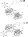
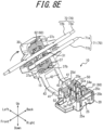
- the first housing 20 and the second housing 30 are pressed approximately in parallel in a direction in which the first housing 20 and the second housing 30 approach each other, using a general tool such as a pair of pliers. Consequently, each second locking protrusion 37a engages with the corresponding first locking protrusion 25b. Each protrusion wall 37c is fitted into the corresponding notch 25e.
- the first housing 20 is accommodated in the second housing 30, and the first locking portions 25 and the second locking portions 37 engage with each other inside the first housing 20 and the second housing 30 fitted to each other.
- the elastic first locking portion 25 tries to elastically deform outward by an elastic force from the inside to the outside due to the expansion or swelling of the filler 60. Since the connector 10 has the locking portions inside, such outward elastic deformation of the first locking portion 25 further strengthens the engagement between the first locking portion 25 and the second locking portion 37.
- the state of adhesion between the first housing 20 and the second housing 30 is enhanced. Even when subjected to an elastic force from the inside to the outside, the connector 10 can suppress opening of the first housing 20 and the second housing 30. This effect is seen at normal temperatures but is more noticeable at high temperatures at which the expansion of the filler 60 is greater.
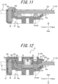
- FIG. 11 is a sectional view along arrow XI-XI in FIG. 8D .
- FIG. 12 is a sectional view along arrow XII-XII in FIG. 1 .
- the state of the first cable 71 will be mainly described below while comparing a pre-fitting state in which the connector 10 provisionally holds the object 70 and a fitting state in which the connector 10 holds the object 70, with reference to FIGS. 11 and 12 .
- the connector 10 in the fitting state is turned upside down from the state in FIG. 1 to correspond to the orientation of the second housing 30 in FIG. 11 , for the sake of convenience.
- the inclination of the first cable 71 becomes steeper.
- the length of the part of the first cable 71 extending from the vicinity of the upper end of the accommodating portion 35a to the accommodating position of the first cable press-contact piece 52 on the front side is longer than that before the fitting, as indicated respectively by a dashed line and a dashed-two dotted line in FIGS. 11 and 12 . Accordingly, the position of the end of the first cable 71 in the accommodating portion 35a shifts to the fitting side.
- the second cable 72 arranged side by side with the first cable 71 in the right-left direction is inserted and held in the pair of second cable holding grooves 34a, in the same manner as the back part of the first cable 71.
- the second cable 72 is located between the pair of slopes 34e and the pair of slopes 23a.
- the second cable 72 has its intermediate part linearly extending in the connector 10.
- the second cable 72 bends on the front and back sides in the connector 10.
- the second cable 72 extends from the pair of second cable holding grooves 34a forward and backward to the outside of the connector 10.
- the receiving portion 36 receives the excess of the filler 60 extruded from the accommodating portion 35a.
- the front half part of the receiving portion 36 gradually widens backward from the accommodating portion 35a side, so that the filler 60 which has moved to the receiving portion 36 diffuses in the receiving portion 36 by the pressing force of the foregoing press.
- the filler 60 diffused in the front half part of the receiving portion 36 comes into contact with the braking portion 36a, the diffusion is prevented.
- the color of the housing 15 may be the same as the color of the filler 60, or different from the color of the filler 60 to ease visual observation.
- the connector 10 achieves protection treatment for the end of the object 70 with good workability, and improves long-term reliability for protection. More specifically, in the expanded state or the fitting state of the first housing 20 and the second housing 30, the filler 60 covers the end of the object 70 in the accommodating portion 35a, so that the end is isolated from the outside. Thus, the connector 10 can achieve protection treatment such as waterproofing, dustproofing, insulation, and rustproofing for the end. Moreover, as a result of the accommodating portion 35a being formed to apply the protection treatment, the assembly operator or the like does not need to use other components such as insulating tape or a waterproof cap. For such a connector 10, component count and man-hour are reduced, and workability is improved.
- the object 70 extends from the accommodating portion 35a recessed in a direction different from the extending direction of the object 70 and bends. This enhances the tolerance to a tensile force acting on the object 70. More specifically, even when a backward tensile force acts on the object 70, the position of the object 70 in the backward direction is regulated because the part of the object 70 on the tip side of the bend part is accommodated in the accommodating portion 35a recessed in a direction different from the backward direction.
- the accommodating portion 35a thus functions as a retainer by applying resistance to a force which attempts to separate the object 70 from the connector 10 and preventing the object 70 from coming out easily.
- the accommodating portion 35a keeps the object 70 from being misaligned in the extending direction, i.e. the backward direction, so that the provisional holding of the object 70 and the adhesion of the filler 60 to the object 70 are improved.
- the recessing direction of the accommodating portion 35a being approximately orthogonal to the extending direction of the object 70, the foregoing retention function for the object 70 is further enhanced, and the provisional holding of the object 70 and the adhesion of the filler 60 to the object 70 are further improved.
- the connector 10 can further enhance the retention function for the object 70 and the effect regarding the provisional holding of the object 70 and the adhesion of the filler 60 to the object 70.
- the connector 10 can achieve protection treatment for the end of the object 70 more effectively.
- the connector 10 can achieve stable protection effect by suppressing influence of variations in operation. More specifically, as a result of the housing 15 including the receiving portion 36, an excess of the filler 60 moves from the accommodating portion 35a, so that the connector 10 can suppress imperfect provisional holding and holding of the object 70 caused by an excessive repulsive force of the filler 60. Moreover, the connector 10 can suppress hindrance of fitting by an excess of the filler 60 and opening between the first housing 20 and the second housing 30 after the fitting. The connector 10 can thus provide stable protection functions regardless of variations in operation by the assembly operator or the like.
- the receiving portion 36 including the braking portion 36a As a result of the receiving portion 36 including the braking portion 36a, the flow of the filler 60 from the accommodating portion 35a to the receiving portion 36 is subjected to resistance. The filler 60 is therefore prevented from flowing out excessively.
- the amount of the filler 60 in the accommodating portion 35a decreases or becomes insufficient to achieve appropriate protection functions as a result of the position of the end of the object 70 shifting in the accommodating portion 35a or the filler 60 moving in the fitting state, an excess of the filler 60 returns into the accommodating portion 35a.
- the connector 10 can thus provide protection functions for the end of the object 70 more reliably.
- the connector 10 can achieve the foregoing effect relating to the braking portion 36a more remarkably.
- the assembly operator or the like can visually determine an excess of the filler 60.
- the assembly operator or the like can visually determine proper insertion of the object 70 and completion of fitting of the housing 15 based on an excess of the filler 60 exposed to the outside.
- the connector 10 can therefore achieve the foregoing effect relating to the receiving portion 36 exposed to the outside more remarkably. This improves the operating accuracy and yield on site by the assembly operator or the like.
- the shape, position, and number of each component described above are not limited to those in the above description and the illustration in the drawings.
- the shape, position, and number of each component may be freely set as long as its functions can be achieved.
- the method of attaching the connector 10 to the object 70 is not limited to that in the above description.
- the method of attaching the connector 10 to the object 70 may be any method with which the connector 10 can be attached to the object 70 so as to achieve its functions.
- the connector 10 may not include the connection portion 40 as long as fittability can be maintained.
- the second housing 30 separate from the first housing 20 may be fitted to the first housing 20 downward from above.
- the method of holding the object 70 by the housing 15 and the recessing direction of the accommodating portion 35a are not limited to such.
- the holding method and the recessing direction may be any method and direction as long as the filler 60 covers the end of the object 70 in the accommodating portion 35a.
- the housing 15 may hold the object 70 without bending the object 70.
- the accommodating portion 35a may be a recess that is recessed in the same direction as the extending direction of the object 70.
- the accommodating portion 35a is a recess that is approximately rectangular in a top view
- the shape of the accommodating portion 35a is not limited to such.
- the accommodating portion 35a may be a recess of a mortar shape.
- Such an accommodating portion 35a can appropriately accommodate objects 70 of different diameters. This enhances the versatility of the connector 10.
- FIG. 14 is a top view of a connector 10 according to a first modification.
- FIG. 15 is a top view of a connector 10 according to a second modification.
- the shape of the braking portion 36a is not limited to such.
- the shape of the braking portion 36a may be any shape as long as the diffusion of the filler 60 can be regulated.
- a pair of right and left protrusions forming the braking portion 36a may have an inverse tapered shape that is obliquely inclined toward the inside of the receiving portion 36 in the forward direction, as illustrated in FIG. 14 .
- the right-left spacing between the pair of protrusions may gradually narrow in the forward direction.
- a pair of right and left protrusions forming the braking portion 36a may have a tapered shape that is obliquely inclined toward the inside of the receiving portion 36 in the backward direction, as illustrated in FIG. 15 .
- FIG. 16 is a top view of a connector 10 according to a third modification.
- FIG. 17 is a top view of a connector 10 according to a fourth modification.
- the receiving portion 36 has the protrusion-shaped braking portion 36a
- the receiving portion 36 may not include a protrusion portion.
- the braking portion 36a may be a part in the receiving portion 36 where the width in a direction approximately orthogonal to the moving direction of the filler 60 narrows in the moving direction.
- the braking portion 36a may be a taper portion in which the width of the receiving portion 36 in a direction approximately orthogonal to the moving direction of the filler 60 gradually narrows toward the side opposite to the accommodating portion 35a.
- the braking portion 36a may be a taper portion that is formed in the back half part of the receiving portion 36 and in which the right-left width of the whole receiving portion 36 gradually narrows in the backward direction, as illustrated in FIG. 16 .
- the braking portion 36a may be two taper portions in which the spacing between each of the right and left surfaces of a protrusion of an inverse tapered shape formed in the back half part of the receiving portion 36 and the corresponding one of the right and left inner surfaces of the receiving portion 36 gradually narrows in the backward direction, as illustrated in FIG. 17 .
- the receiving portion 36 is not limited to such.
- the receiving portion 36 may be formed inside the housing 15 as long as it can receive an excess of the filler 60 extruded from the accommodating portion 35a.
- the shape of the engagement surface A1 is not limited to such.
- the engagement surface A1 may be inclined downward from the inside toward the outside of the fitted first housing 20 and second housing 30. With such a cross-sectional shape, the engagement force is enhanced, and the possibility of unlocking of the first locking protrusion 25b and the second locking protrusion 37a is further reduced.
- first locking portion 25 is formed in the first housing 20 and the second locking portion 37 is formed in the second housing 30
- first locking portion 25 and the second locking portion 37 are not limited to such.
- the first locking portion 25 having elasticity may be formed in the second housing 30 not including the relay contact 50
- the second locking portion 37 may be formed in the first housing 20 including the relay contact 50.
- the formation positions of the first locking portion 25 and the second locking portion 37 in the first housing 20 and the second housing 30 are not limited to the positions described above.
- the formation positions may be any positions with which the first housing 20 and the second housing 30 are fitted and held in a locked state.
- first locking portion 25 and the second locking portion 37 respectively have the first locking protrusion 25b and the second locking protrusion 37a and the first locking protrusion 25b and the second locking protrusion 37a engage with each other
- the locking means is not limited to such.
- the first locking portion 25 and the second locking portion 37 may have any locking means.
- first housing 20 and the second housing 30 are respectively loaded with the first filler 61 and the second filler 62
- the disclosed technique is not limited to such. Only one of the first housing 20 and the second housing 30 may be loaded with the filler 60 as long as appropriate protection functions can be achieved.
Landscapes
- Engineering & Computer Science (AREA)
- Manufacturing & Machinery (AREA)
- Connector Housings Or Holding Contact Members (AREA)
- Connections By Means Of Piercing Elements, Nuts, Or Screws (AREA)
- Manufacturing Of Electrical Connectors (AREA)
Claims (7)
- Verbinder (10), der konfiguriert ist, um ein Objekt (70), insbesondere zwei Kabel (71, 72), in elektrische Leitung zu versetzen, wobei der Verbinder (10) aufweist:ein erstes Gehäuse (20) und ein zweites Gehäuse (30), die zusammensetzbar sind, undeinen Füllstoff (60), mit dem mindestens eines von dem ersten und dem zweiten Gehäuse (20, 30) bestückt ist,wobeidas zweite Gehäuse (30) einen Aufnahmeabschnitt (35a) aufweist, der konfiguriert ist, um ein Ende des Objekts (70) aufzunehmen,der Füllstoff (60) konfiguriert ist, um das Ende des Objekts (70) in dem Aufnahmeabschnitt (35a) zu bedecken,der Aufnahmeabschnitt (35a) eine Aussparung ist, die in einer Richtung ausgespart ist, die sich von einer Erstreckungsrichtung des Objekts (70) unterscheidet,das zweite Gehäuse (30) konfiguriert ist, um das Objekt (70) in einem Zustand zu halten, in dem sich das Objekt (70) von dem Aufnahmeabschnitt (35a) aus erstreckt und gebogen ist,dadurch gekennzeichnet, dassdas zweite Gehäuse (30) Objekt-Stützarmabschnitte (32a und 32b) aufweist, die in der Erstreckungsrichtung des Objekts (70) von einer Vorder- und einer Rückseite einer Außenumfangswand (30a) des zweiten Gehäuses (30) hervorstehen, unddie Außenumfangswand (30a) von Außenumfangsrändern, die sich an einem Boden des zweiten Gehäuses (30) befinden, nach oben hervorsteht, wobei sie ein Inneres des zweiten Gehäuses (30) umgibt.
- Verbinder (10) gemäß Anspruch 1, wobei der Füllstoff (60) konfiguriert ist, um das Ende des Objekts (70) in dem Aufnahmeabschnitt (35a) in einem Zusammensetz-Zustand zu bedecken, in dem das erste und das zweite Gehäuse (20, 30) zusammengesetzt sind.
- Verbinder (10) gemäß Anspruch 1 oder 2, wobei die Richtung, in der der Aufnahmeabschnitt (35a) ausgespart ist, ungefähr orthogonal zur Erstreckungsrichtung des Objekts (70) ist.
- Verbinder (10) gemäß irgendeinem der Ansprüche 1 bis 3, wobei das zweite Gehäuse (30) einen Wandabschnitt (35b) benachbart zu dem Aufnahmeabschnitt (35a) entlang des Objekts (70) aufweist.
- Verbinder (10) gemäß Anspruch 4, wobei ein Wandabschnitt (22b, 35b) in jedem von dem ersten und dem zweiten Gehäuse (20, 30) ausgebildet ist und das Objekt (70) konfiguriert ist, um zwischen einem Paar der Wandabschnitte (22b, 35b) in einem Zusammensetz-Zustand angeordnet zu sein, in dem das erste und das zweite Gehäuse (20, 30) zusammengesetzt sind.
- Anbringungsverfahren zum Anbringen des Verbinders (10) gemäß irgendeinem der Ansprüche 1 bis 5 an dem Objekt (70), wobei der Verbinder (10) konfiguriert ist, um das Objekt (70) in Leitung zu versetzen, wobei das Anbringungsverfahren aufweist:Beladen des ersten Gehäuses (20) und des zweiten Gehäuses (30) mit dem Füllstoff (60),Einsetzen des Endes des Objekts (70) in den mit dem Füllstoff beladenen Aufnahmeabschnitt (35a),Zusammensetzen des ersten Gehäuses (20) und des zweiten Gehäuses (30) undBedecken des Endes des Objekts (70) mit dem Füllstoff (60) in dem Aufnahmeabschnitt (35a).
- Anbringungsverfahren gemäß Anspruch 6, aufweisend:
Biegen des Objekts (70) und vorläufiges Halten des Objekts (70) in dem zweiten Gehäuse (30) nach dem Einsetzen.
Applications Claiming Priority (2)
| Application Number | Priority Date | Filing Date | Title |
|---|---|---|---|
| JP2017246954A JP6993214B2 (ja) | 2017-12-22 | 2017-12-22 | コネクタ及び取付方法 |
| PCT/JP2018/044620 WO2019124063A1 (ja) | 2017-12-22 | 2018-12-04 | コネクタ及び取付方法 |
Publications (3)
| Publication Number | Publication Date |
|---|---|
| EP3731350A1 EP3731350A1 (de) | 2020-10-28 |
| EP3731350A4 EP3731350A4 (de) | 2021-09-15 |
| EP3731350B1 true EP3731350B1 (de) | 2025-02-26 |
Family
ID=66993485
Family Applications (1)
| Application Number | Title | Priority Date | Filing Date |
|---|---|---|---|
| EP18890614.3A Active EP3731350B1 (de) | 2017-12-22 | 2018-12-04 | Verbinder und befestigungsverfahren |
Country Status (6)
| Country | Link |
|---|---|
| US (1) | US11251545B2 (de) |
| EP (1) | EP3731350B1 (de) |
| JP (1) | JP6993214B2 (de) |
| KR (1) | KR102418989B1 (de) |
| CN (1) | CN111542971B (de) |
| WO (1) | WO2019124063A1 (de) |
Family Cites Families (10)
| Publication number | Priority date | Publication date | Assignee | Title |
|---|---|---|---|---|
| US5594210A (en) * | 1994-09-28 | 1997-01-14 | Yazaki Corporation | Waterproof protective cover |
| JP3119119B2 (ja) * | 1995-05-17 | 2000-12-18 | 住友電装株式会社 | 圧接ジョイントコネクタ |
| JP3408391B2 (ja) * | 1997-04-02 | 2003-05-19 | 矢崎総業株式会社 | コネクタ |
| JP3730380B2 (ja) * | 1997-10-09 | 2006-01-05 | 矢崎総業株式会社 | 防水コネクタ及びその製造方法 |
| JP2004327174A (ja) * | 2003-04-23 | 2004-11-18 | Yazaki Corp | 防水コネクタ |
| FR2854282A1 (fr) * | 2003-04-23 | 2004-10-29 | Yazaki Corp | Connecteur etanche a l'eau |
| JP2005149936A (ja) * | 2003-11-17 | 2005-06-09 | Fujikura Ltd | 圧接ジョイントコネクタ |
| JP2005251400A (ja) * | 2004-03-01 | 2005-09-15 | Yazaki Corp | 電線端末用キャップ |
| JP5787864B2 (ja) * | 2012-12-06 | 2015-09-30 | 京セラコネクタプロダクツ株式会社 | 分岐コネクタ |
| JP6358125B2 (ja) * | 2015-02-18 | 2018-07-18 | 株式会社オートネットワーク技術研究所 | コネクタ |
-
2017
- 2017-12-22 JP JP2017246954A patent/JP6993214B2/ja active Active
-
2018
- 2018-12-04 KR KR1020207016669A patent/KR102418989B1/ko active Active
- 2018-12-04 EP EP18890614.3A patent/EP3731350B1/de active Active
- 2018-12-04 CN CN201880079563.0A patent/CN111542971B/zh active Active
- 2018-12-04 US US16/955,673 patent/US11251545B2/en active Active
- 2018-12-04 WO PCT/JP2018/044620 patent/WO2019124063A1/ja not_active Ceased
Also Published As
| Publication number | Publication date |
|---|---|
| US11251545B2 (en) | 2022-02-15 |
| CN111542971B (zh) | 2021-10-26 |
| JP6993214B2 (ja) | 2022-01-13 |
| KR20200080313A (ko) | 2020-07-06 |
| WO2019124063A1 (ja) | 2019-06-27 |
| EP3731350A1 (de) | 2020-10-28 |
| EP3731350A4 (de) | 2021-09-15 |
| CN111542971A (zh) | 2020-08-14 |
| JP2019114416A (ja) | 2019-07-11 |
| US20210021058A1 (en) | 2021-01-21 |
| KR102418989B1 (ko) | 2022-07-08 |
Similar Documents
| Publication | Publication Date | Title |
|---|---|---|
| US11043757B2 (en) | Electrical connector with filler surrounding a wall that surrounds a contact | |
| JP4219778B2 (ja) | 防水圧接コネクタ | |
| EP3605742B1 (de) | Verbinder | |
| US10833447B2 (en) | Connector | |
| EP3731349B1 (de) | Verbinder | |
| EP3731350B1 (de) | Verbinder und befestigungsverfahren | |
| US10971829B2 (en) | Connector and package body | |
| US10797410B2 (en) | Connector | |
| CN110383584B (zh) | 连接器 | |
| CA2462104C (en) | Connector for flat cable |
Legal Events
| Date | Code | Title | Description |
|---|---|---|---|
| STAA | Information on the status of an ep patent application or granted ep patent |
Free format text: STATUS: THE INTERNATIONAL PUBLICATION HAS BEEN MADE |
|
| PUAI | Public reference made under article 153(3) epc to a published international application that has entered the european phase |
Free format text: ORIGINAL CODE: 0009012 |
|
| STAA | Information on the status of an ep patent application or granted ep patent |
Free format text: STATUS: REQUEST FOR EXAMINATION WAS MADE |
|
| 17P | Request for examination filed |
Effective date: 20200608 |
|
| AK | Designated contracting states |
Kind code of ref document: A1 Designated state(s): AL AT BE BG CH CY CZ DE DK EE ES FI FR GB GR HR HU IE IS IT LI LT LU LV MC MK MT NL NO PL PT RO RS SE SI SK SM TR |
|
| AX | Request for extension of the european patent |
Extension state: BA ME |
|
| DAV | Request for validation of the european patent (deleted) | ||
| DAX | Request for extension of the european patent (deleted) | ||
| REG | Reference to a national code |
Ref country code: DE Ref legal event code: R079 Free format text: PREVIOUS MAIN CLASS: H01R0013520000 Ipc: H01R0004700000 Ref country code: DE Ref legal event code: R079 Ref document number: 602018079701 Country of ref document: DE Free format text: PREVIOUS MAIN CLASS: H01R0013520000 Ipc: H01R0004700000 |
|
| A4 | Supplementary search report drawn up and despatched |
Effective date: 20210813 |
|
| RIC1 | Information provided on ipc code assigned before grant |
Ipc: H01R 4/2433 20180101ALI20210809BHEP Ipc: H01R 43/00 20060101ALI20210809BHEP Ipc: H01R 4/70 20060101AFI20210809BHEP |
|
| P01 | Opt-out of the competence of the unified patent court (upc) registered |
Effective date: 20230505 |
|
| STAA | Information on the status of an ep patent application or granted ep patent |
Free format text: STATUS: EXAMINATION IS IN PROGRESS |
|
| 17Q | First examination report despatched |
Effective date: 20231013 |
|
| GRAP | Despatch of communication of intention to grant a patent |
Free format text: ORIGINAL CODE: EPIDOSNIGR1 |
|
| STAA | Information on the status of an ep patent application or granted ep patent |
Free format text: STATUS: GRANT OF PATENT IS INTENDED |
|
| INTG | Intention to grant announced |
Effective date: 20240919 |
|
| RIN1 | Information on inventor provided before grant (corrected) |
Inventor name: OHARA, SHIGEKI Inventor name: HATA, TETSUYA |
|
| GRAS | Grant fee paid |
Free format text: ORIGINAL CODE: EPIDOSNIGR3 |
|
| GRAA | (expected) grant |
Free format text: ORIGINAL CODE: 0009210 |
|
| STAA | Information on the status of an ep patent application or granted ep patent |
Free format text: STATUS: THE PATENT HAS BEEN GRANTED |
|
| AK | Designated contracting states |
Kind code of ref document: B1 Designated state(s): AL AT BE BG CH CY CZ DE DK EE ES FI FR GB GR HR HU IE IS IT LI LT LU LV MC MK MT NL NO PL PT RO RS SE SI SK SM TR |
|
| REG | Reference to a national code |
Ref country code: GB Ref legal event code: FG4D |
|
| REG | Reference to a national code |
Ref country code: CH Ref legal event code: EP |
|
| REG | Reference to a national code |
Ref country code: DE Ref legal event code: R096 Ref document number: 602018079701 Country of ref document: DE |
|
| REG | Reference to a national code |
Ref country code: IE Ref legal event code: FG4D |
|
| REG | Reference to a national code |
Ref country code: NL Ref legal event code: MP Effective date: 20250226 |
|
| PG25 | Lapsed in a contracting state [announced via postgrant information from national office to epo] |
Ref country code: RS Free format text: LAPSE BECAUSE OF FAILURE TO SUBMIT A TRANSLATION OF THE DESCRIPTION OR TO PAY THE FEE WITHIN THE PRESCRIBED TIME-LIMIT Effective date: 20250526 |
|
| PG25 | Lapsed in a contracting state [announced via postgrant information from national office to epo] |
Ref country code: FI Free format text: LAPSE BECAUSE OF FAILURE TO SUBMIT A TRANSLATION OF THE DESCRIPTION OR TO PAY THE FEE WITHIN THE PRESCRIBED TIME-LIMIT Effective date: 20250226 |
|
| PG25 | Lapsed in a contracting state [announced via postgrant information from national office to epo] |
Ref country code: PL Free format text: LAPSE BECAUSE OF FAILURE TO SUBMIT A TRANSLATION OF THE DESCRIPTION OR TO PAY THE FEE WITHIN THE PRESCRIBED TIME-LIMIT Effective date: 20250226 |
|
| PG25 | Lapsed in a contracting state [announced via postgrant information from national office to epo] |
Ref country code: ES Free format text: LAPSE BECAUSE OF FAILURE TO SUBMIT A TRANSLATION OF THE DESCRIPTION OR TO PAY THE FEE WITHIN THE PRESCRIBED TIME-LIMIT Effective date: 20250226 |
|
| REG | Reference to a national code |
Ref country code: LT Ref legal event code: MG9D |
|
| PG25 | Lapsed in a contracting state [announced via postgrant information from national office to epo] |
Ref country code: IS Free format text: LAPSE BECAUSE OF FAILURE TO SUBMIT A TRANSLATION OF THE DESCRIPTION OR TO PAY THE FEE WITHIN THE PRESCRIBED TIME-LIMIT Effective date: 20250626 Ref country code: NO Free format text: LAPSE BECAUSE OF FAILURE TO SUBMIT A TRANSLATION OF THE DESCRIPTION OR TO PAY THE FEE WITHIN THE PRESCRIBED TIME-LIMIT Effective date: 20250526 |
|
| PG25 | Lapsed in a contracting state [announced via postgrant information from national office to epo] |
Ref country code: NL Free format text: LAPSE BECAUSE OF FAILURE TO SUBMIT A TRANSLATION OF THE DESCRIPTION OR TO PAY THE FEE WITHIN THE PRESCRIBED TIME-LIMIT Effective date: 20250226 |
|
| PG25 | Lapsed in a contracting state [announced via postgrant information from national office to epo] |
Ref country code: HR Free format text: LAPSE BECAUSE OF FAILURE TO SUBMIT A TRANSLATION OF THE DESCRIPTION OR TO PAY THE FEE WITHIN THE PRESCRIBED TIME-LIMIT Effective date: 20250226 |
|
| PG25 | Lapsed in a contracting state [announced via postgrant information from national office to epo] |
Ref country code: PT Free format text: LAPSE BECAUSE OF FAILURE TO SUBMIT A TRANSLATION OF THE DESCRIPTION OR TO PAY THE FEE WITHIN THE PRESCRIBED TIME-LIMIT Effective date: 20250626 Ref country code: LV Free format text: LAPSE BECAUSE OF FAILURE TO SUBMIT A TRANSLATION OF THE DESCRIPTION OR TO PAY THE FEE WITHIN THE PRESCRIBED TIME-LIMIT Effective date: 20250226 |
|
| PG25 | Lapsed in a contracting state [announced via postgrant information from national office to epo] |
Ref country code: BG Free format text: LAPSE BECAUSE OF FAILURE TO SUBMIT A TRANSLATION OF THE DESCRIPTION OR TO PAY THE FEE WITHIN THE PRESCRIBED TIME-LIMIT Effective date: 20250226 Ref country code: GR Free format text: LAPSE BECAUSE OF FAILURE TO SUBMIT A TRANSLATION OF THE DESCRIPTION OR TO PAY THE FEE WITHIN THE PRESCRIBED TIME-LIMIT Effective date: 20250527 |
|
| REG | Reference to a national code |
Ref country code: AT Ref legal event code: MK05 Ref document number: 1771622 Country of ref document: AT Kind code of ref document: T Effective date: 20250226 |
|
| PG25 | Lapsed in a contracting state [announced via postgrant information from national office to epo] |
Ref country code: SE Free format text: LAPSE BECAUSE OF FAILURE TO SUBMIT A TRANSLATION OF THE DESCRIPTION OR TO PAY THE FEE WITHIN THE PRESCRIBED TIME-LIMIT Effective date: 20250226 |
|
| PG25 | Lapsed in a contracting state [announced via postgrant information from national office to epo] |
Ref country code: SM Free format text: LAPSE BECAUSE OF FAILURE TO SUBMIT A TRANSLATION OF THE DESCRIPTION OR TO PAY THE FEE WITHIN THE PRESCRIBED TIME-LIMIT Effective date: 20250226 |
|
| PG25 | Lapsed in a contracting state [announced via postgrant information from national office to epo] |
Ref country code: DK Free format text: LAPSE BECAUSE OF FAILURE TO SUBMIT A TRANSLATION OF THE DESCRIPTION OR TO PAY THE FEE WITHIN THE PRESCRIBED TIME-LIMIT Effective date: 20250226 |
|
| PG25 | Lapsed in a contracting state [announced via postgrant information from national office to epo] |
Ref country code: IT Free format text: LAPSE BECAUSE OF FAILURE TO SUBMIT A TRANSLATION OF THE DESCRIPTION OR TO PAY THE FEE WITHIN THE PRESCRIBED TIME-LIMIT Effective date: 20250226 |
|
| PG25 | Lapsed in a contracting state [announced via postgrant information from national office to epo] |
Ref country code: AT Free format text: LAPSE BECAUSE OF FAILURE TO SUBMIT A TRANSLATION OF THE DESCRIPTION OR TO PAY THE FEE WITHIN THE PRESCRIBED TIME-LIMIT Effective date: 20250226 |
|
| PG25 | Lapsed in a contracting state [announced via postgrant information from national office to epo] |
Ref country code: EE Free format text: LAPSE BECAUSE OF FAILURE TO SUBMIT A TRANSLATION OF THE DESCRIPTION OR TO PAY THE FEE WITHIN THE PRESCRIBED TIME-LIMIT Effective date: 20250226 Ref country code: CZ Free format text: LAPSE BECAUSE OF FAILURE TO SUBMIT A TRANSLATION OF THE DESCRIPTION OR TO PAY THE FEE WITHIN THE PRESCRIBED TIME-LIMIT Effective date: 20250226 |
|
| PG25 | Lapsed in a contracting state [announced via postgrant information from national office to epo] |
Ref country code: RO Free format text: LAPSE BECAUSE OF FAILURE TO SUBMIT A TRANSLATION OF THE DESCRIPTION OR TO PAY THE FEE WITHIN THE PRESCRIBED TIME-LIMIT Effective date: 20250226 |
|
| PG25 | Lapsed in a contracting state [announced via postgrant information from national office to epo] |
Ref country code: SK Free format text: LAPSE BECAUSE OF FAILURE TO SUBMIT A TRANSLATION OF THE DESCRIPTION OR TO PAY THE FEE WITHIN THE PRESCRIBED TIME-LIMIT Effective date: 20250226 |
|
| REG | Reference to a national code |
Ref country code: DE Ref legal event code: R097 Ref document number: 602018079701 Country of ref document: DE |
|
| PLBE | No opposition filed within time limit |
Free format text: ORIGINAL CODE: 0009261 |
|
| STAA | Information on the status of an ep patent application or granted ep patent |
Free format text: STATUS: NO OPPOSITION FILED WITHIN TIME LIMIT |
|
| PGFP | Annual fee paid to national office [announced via postgrant information from national office to epo] |
Ref country code: DE Payment date: 20251028 Year of fee payment: 8 |
|
| 26N | No opposition filed |
Effective date: 20251127 |