EP3728758B1 - Baustoff, insbesondere dachbaustoff - Google Patents
Baustoff, insbesondere dachbaustoff Download PDFInfo
- Publication number
- EP3728758B1 EP3728758B1 EP18836451.7A EP18836451A EP3728758B1 EP 3728758 B1 EP3728758 B1 EP 3728758B1 EP 18836451 A EP18836451 A EP 18836451A EP 3728758 B1 EP3728758 B1 EP 3728758B1
- Authority
- EP
- European Patent Office
- Prior art keywords
- layer
- building material
- material according
- electrode structures
- cellulose
- Prior art date
- Legal status (The legal status is an assumption and is not a legal conclusion. Google has not performed a legal analysis and makes no representation as to the accuracy of the status listed.)
- Active
Links
Images
Classifications
-
- E—FIXED CONSTRUCTIONS
- E04—BUILDING
- E04D—ROOF COVERINGS; SKY-LIGHTS; GUTTERS; ROOF-WORKING TOOLS
- E04D13/00—Special arrangements or devices in connection with roof coverings; Protection against birds; Roof drainage ; Sky-lights
- E04D13/006—Provisions for detecting water leakage
-
- E—FIXED CONSTRUCTIONS
- E04—BUILDING
- E04D—ROOF COVERINGS; SKY-LIGHTS; GUTTERS; ROOF-WORKING TOOLS
- E04D5/00—Roof covering by making use of flexible material, e.g. supplied in roll form
- E04D5/10—Roof covering by making use of flexible material, e.g. supplied in roll form by making use of compounded or laminated materials, e.g. metal foils or plastic films coated with bitumen
-
- E—FIXED CONSTRUCTIONS
- E04—BUILDING
- E04D—ROOF COVERINGS; SKY-LIGHTS; GUTTERS; ROOF-WORKING TOOLS
- E04D5/00—Roof covering by making use of flexible material, e.g. supplied in roll form
- E04D5/12—Roof covering by making use of flexible material, e.g. supplied in roll form specially modified, e.g. perforated, with granulated surface, with attached pads
-
- E—FIXED CONSTRUCTIONS
- E04—BUILDING
- E04D—ROOF COVERINGS; SKY-LIGHTS; GUTTERS; ROOF-WORKING TOOLS
- E04D5/00—Roof covering by making use of flexible material, e.g. supplied in roll form
- E04D5/14—Fastening means therefor
- E04D5/148—Fastening means therefor fastening by gluing
-
- G—PHYSICS
- G01—MEASURING; TESTING
- G01M—TESTING STATIC OR DYNAMIC BALANCE OF MACHINES OR STRUCTURES; TESTING OF STRUCTURES OR APPARATUS, NOT OTHERWISE PROVIDED FOR
- G01M3/00—Investigating fluid-tightness of structures
- G01M3/02—Investigating fluid-tightness of structures by using fluid or vacuum
- G01M3/04—Investigating fluid-tightness of structures by using fluid or vacuum by detecting the presence of fluid at the leakage point
- G01M3/16—Investigating fluid-tightness of structures by using fluid or vacuum by detecting the presence of fluid at the leakage point using electric detection means
-
- E—FIXED CONSTRUCTIONS
- E04—BUILDING
- E04D—ROOF COVERINGS; SKY-LIGHTS; GUTTERS; ROOF-WORKING TOOLS
- E04D13/00—Special arrangements or devices in connection with roof coverings; Protection against birds; Roof drainage ; Sky-lights
- E04D13/002—Provisions for preventing vegetational growth, e.g. fungi, algae or moss
Definitions
- the invention relates to a building material, in particular roofing material, in roll or web form, with a composite structure which has a first layer, a carrier material layer and an adhesive layer arranged between the carrier material layer and the first layer, wherein the first layer is firmly connected to the adhesive layer and the carrier material layer is detachably connected to the adhesive layer.
- roofing materials essentially have a first layer, a carrier material layer and an adhesive layer arranged between the carrier material layer and the first layer. These layers are detachably connected to one another via the adhesive layer in order to attach them to other building materials.
- the disadvantage is that after their installation it is relatively difficult or even impossible to determine whether the installation was carried out as intended, especially since after their installation they are usually no longer accessible for inspection.
- the invention therefore has the task, based on the state of the art described at the outset, of structurally modifying a building material, in particular a roofing material, in roll or sheet form in such a way that it can be checked - also with regard to its stability - even after it has been installed.
- the invention solves the problem by the features of claim 1.
- the first layer has both cellulose and, on the side of the layer facing away from the carrier material layer, at least one printed, electrically conductive electrode structure which forms a sensor with the cellulose of the first layer: this can open up the possibility of checking the building material in roll or web form using the sensor, which is particularly passive, for example capacitive, even after it has been installed.
- the cellulose of the first layer in the sensor function, conclusions can be drawn about the functionality of the building material according to the invention based on the sensor data and thus, among other things, the installation state can be checked for correctness - even in the case of concealed installation or inaccessibility when installed.
- the building material in roll or sheet form can also help to monitor the functional reliability of the component.
- the building or roof can be monitored for water ingress, condensation or moisture in general, as well as unexpected temperature fluctuations, etc.
- the building material according to the invention can therefore not only be checked for correct use after its installation, but can also contribute to the monitoring of the building structure.
- the building material in roll or sheet form can be a roofing material, a roofing sheet, a drywall material or a flooring material, etc.
- the measurement data acquisition of the building material is further improved by repeatedly providing electrode structures over the, preferably entire, length of the building material, which form a sensor with the cellulose of the first layer. In addition, this allows the building material to be better monitored over its installed length.
- the electrode structures are arranged in series one after the other in order to be able to check the correctness of the installation state over the length of the building material.
- the electrode structures are arranged in several rows, in particular in two, offset from one another - for example, offset from one another in the middle with a gap - in order to ensure sufficient monitoring or control of the building material.
- the first layer has printed electrical conductors that electrically connect the electrode structures running in the longitudinal direction of the web, the electrical contacting of the building material can be facilitated.
- the design effort for the building material can be further reduced if the electrical conductors consist of a forward conductor and a return conductor, to which the electrode structures are electrically connected in parallel.
- the parallel connection of the electrode structures can also make it easier to electrically contact the building material.
- the spatial resolution of detected defects can be further increased if each row of electrode structures is electrically connected in parallel to a forward and a return conductor.
- the construction of the building material can be further simplified - without having to fear any restrictions in function.
- a comparatively easy-to-use possibility for electrical contacting of the electrode structure can arise if electrical conductors run along the longitudinal edge of the track.
- the sensor sensitivity can be further increased if the printed electrically conductive electrode structure consists of a solid paste or ink with a carbon base.
- the first layer contains a biocidal, fungicidal and/or bactericidal agent as a filler, this can help to improve the durability of the building material.
- the application of the electrode structure can be facilitated and the sensitivity of the sensor further improved if the first layer has a cellulose content of 60 to 90%, preferably 65 to 79%, in particular 72%, and the remainder is filler.
- the stability of the building material can be further increased if the first layer has a surface weight of more than 70 g/m 2 , in particular 90 g/m 2 .
- Constructive simplicity can be achieved if the first layer is a label paper.
- the carrier material layer has a release agent, in particular silicone, this can further facilitate the handling of the building material - especially if the carrier material layer is to be removed from the first layer with the electrode structure.
- a particularly precise inspection of the building material can be made possible if the electrode structure forms a humidity and/or temperature sensor with the cellulose of the first layer.
- the design of the building material can be further simplified if the electrode structure has interlocking finger electrodes.
- the distance between two consecutive electrode structures is greater than or equal to 0.5 m, in particular greater than or equal to 2 m.
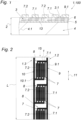
- a building material 1, 100 namely a roofing material, is shown in web form, which was unrolled from a roll (not shown).
- the building material 1, 100 has a composite structure 2, namely a first layer 3, a carrier material layer 4 and an adhesive layer 5 arranged between the carrier material layer 4 and the first layer 3.
- the carrier material layer 4 can be separated from the first layer 3 if necessary, since the first layer 3 is firmly connected to the adhesive layer 5, while the carrier material layer 4 is detachably connected to the adhesive layer 5.
- the first layer 3 with the adhesive layer 5 can thus be glued to another building material 1, 100 (not shown).
- the carrier material layer 4 has a release agent 4.1, in particular silicone, to facilitate this separation.
- the first layer 3 comprises cellulose 6.
- a printed and electrically conductive electrode structure 7 on the layer side 3.1, which faces away from the carrier material layer 4.
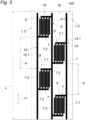
- Such an electrode structure 7 is in Fig. 2 in plan view, for example.
- the electrode structure 7 interacts with the cellulose 6 of the first layer 3 to form a passive sensor 8, namely Moisture sensor, electrical, for example resistive and/or capacitive.
- a moisture level of the cellulose 6 can be determined and the installation state of the building material 1, 100 can be checked.
- a changing dielectric constant of the cellulose 6 can also be detected by adsorption and desorption of water vapor or moisture.
- the capacitive sensor 8 thus reacts to a change in its electrostatic capacity.
- the electrode structure 7 interacts with the cellulose 6 of the first layer 3 to form a temperature sensor.
- interlocking finger electrodes 7.1, 7.2 form the electrode structure 7, which improves the sensitivity of the sensor 8.
- four interlocking finger electrodes 7.1, 7.2 have proven to be sufficient to monitor the building material 1.
- the finger electrodes 7.1, 7.2 can have different distances from each other and/or different lengths and/or widths.
- the finger electrodes 7.1, 7.2 are mirror-symmetrical to each other.
- the building material 1, 100 Due to this functionalization of the building material 1, 100, it can be checked for correct installation even when installed. In addition, the building structure can be monitored using the measurement data from the moisture sensor and/or temperature sensor.
- the building material 1, 100 can therefore be used, for example, to detect water ingress on a roof, which can enable damage to the building structure to be identified early.
- electrode structures 7 are provided repeatedly over the entire length L of the building material 1, 100. This means that the building material 1, 100 can be checked extremely precisely and the building structure can also be monitored seamlessly when installed. Furthermore, it is possible to determine the position or to determine the location of the singularity - which facilitates repair/repair of the building material 1, 100 and/or the building structure.
- the building material 1 according to Fig. 2 has two electrical conductors 9, 10.
- the building material according to Fig. 3 has three electrical conductors 9, 10, 14.
- the building material 1, 100 can thus be electrically contacted relatively easily at one end of the web 1.1, since the first layer 3 also has printed electrical conductors 9, 10, 14, which run in the longitudinal direction 11 of the web, namely along a longitudinal edge 1.2 or 1.3 of the web.
- the electrical conductors 9, 10, 14 form forward and return conductors 9.1, 10.1, 14.1, to which respective forward and return conductors 9.1, 10.1, 14.1 the electrode structures 7 are connected electrically in parallel - like the Figures 2 and 3 to be removed.
- the electrode structures 7 are arranged in rows 15, 16 one after the other, with the electrode structures 7 Fig. 2 in a row 15 and after Fig. 3 are arranged in two rows 15, 16 one after the other. These two rows 15, 16 are offset from each other, preferably offset from each other with a gap, which increases the spatial resolution when detecting a defect in the building material 1.
- the electrode structures 7 are connected in parallel between a first forward conductor 9.1 and a first return conductor 10.1.
- the electrode structures 7 of each row 15, 16 are connected in parallel between the first forward conductor 9.1 and a respective first or second return conductor 10.1 or 14.1.
- the electrode structure 7 is formed by a solid paste or ink with a carbon base, which is applied to the first layer 3 by a printing process.
- This first layer 3 has cellulose 6 - which facilitates printing and also leads to a stable, material-locking connection between the first layer 3 and the electrode structure 7.
- the first layer 3 is provided with a biocidal, fungicidal and/or bactericidal agent as filler 13 or the cellulose 6 is impregnated with it - which gives the building material 1 a high level of durability.
- the filler can also contain a wet strength agent, etc.
- the first layer 3 also has a binding agent application or coating.
- the binding agent or coating color can contain chalk, kaolin, casein, plastic dispersion, antifoaming agents, optical brighteners and/or biocides, etc.
- the adhesive layer 5 has an acrylic base and the carrier material layer 4 consists of a release paper or a release film.
- the adhesive layer 5 has a basis weight of more than 30 g/m 2 , preferably it is 40 g/m 2 .
- the first layer 3 has a basis weight of more than 70 g/m 2 , preferably the thickness is 90 g/m 2 .
- the first layer 3 has a cellulose 6 content of 60 to 90%, preferably 65 to 79%, namely 72%, and the remainder is filler.
- the carrier material layer 4 is preferably a silicone paper as a release paper.
- the distance A between two consecutive electrode structures 7 is greater than or equal to 2 m, which is sufficient to enable a high spatial resolution.
Landscapes
- Engineering & Computer Science (AREA)
- Architecture (AREA)
- Civil Engineering (AREA)
- Structural Engineering (AREA)
- Physics & Mathematics (AREA)
- General Physics & Mathematics (AREA)
- Laminated Bodies (AREA)
Description
- Die Erfindung betrifft einen Baustoff, insbesondere Dachbaustoff, in Rollen- oder Bahnform, mit einer Verbundstruktur, die eine erste Lage, eine Trägermateriallage und eine zwischen Trägermateriallage und ersten Lage angeordnete Klebstoffschicht aufweist, wobei die erste Lage mit der Klebstoffschicht fest verbunden ist und die Trägermateriallage mit der Klebstoffschicht lösbar verbunden ist.
- Aus
WO 2017/061470 A1 is ein flüssigkeitsdetektierendes Element bekannt. - Aus dem Stand der Technik sind ferner aufgerollte Bahnen eines Baustoffs, insbesondere Dachbaustoffs, mit einer Verbundstruktur, beispielsweise für Flachdächer etc., bekannt (
EP0441241B1 ). Derartige Dachbaustoffe weisen im Wesentlichen eine erste Lage, eine Trägermateriallage und eine zwischen Trägermateriallage und ersten Lage angeordnete Klebstoffschicht auf. Diese Lagen sind über die Klebstoffschicht lösbar miteinander verbunden, um diese an andere Baustoffe zu befestigen. Nachteilig kann nach deren Montage vergleichsweise schwer bzw. gar nicht nachvollzogen werden, ob die Montage bestimmungsgemäß erfolgt ist, zumal nach deren Montage diese für eine Überprüfung meist auch nicht mehr zugänglich sind. - Die Erfindung hat sich daher ausgehend vom eingangs geschilderten Stand der Technik die Aufgabe gestellt, einen Baustoff, insbesondere Dachbaustoff, in Rollen- oder Bahnform derart konstruktiv zu verändern, dass dieser selbst nach seiner Montage einer Überprüfung - auch hinsichtlich seiner Standfestigkeit - zugänglich ist.
- Die Erfindung löst die gestellte Aufgabe durch die Merkmale des Anspruchs 1.
- Die erste Lage weist sowohl Cellulose als auch auf der Lagenseite, welche der Trägermateriallage abgewandt ist, mindestens eine aufgedruckte, elektrisch leitfähige Elektrodenstruktur auf, die mit der Cellulose der ersten Lage einen Sensor ausbildet: so kann sich die Möglichkeit eröffnen, den Baustoff in Rollen- oder Bahnform über den, insbesondere passiven, beispielsweise kapazitiven, Sensor auch nach dessen Montage noch zu überprüfen. Über die Einbeziehung der Cellulose der ersten Lage in die Sensorfunktion kann nämlich anhand der Sensordaten auf die Funktionstüchtigkeit des erfindungsgemäßen Baustoffs rückgeschlossen und damit unter anderem der Einbauzustand auf Richtigkeit überprüft werden - dies auch bei verdeckter Montage bzw. Unzugänglichkeit im verbauten Zustand.
- Zudem kann der Baustoff in Rollen- oder Bahnform auch dazu beitragen, die Funktionssicherheit des Bauteils zu überwachen. Anhand der Sensordaten des erfindungsgemäßen Baustoffs kann nämlich beispielsweise das Bauwerk oder Dach auf Wassereintritt, Kondensatbildung bzw. Feuchtigkeit im Allgemeinen sowie auch in Bezug auf unerwartete Temperaturschwankungen etc. überwacht werden.
- Der erfindungsgemäße Baustoff ist daher nicht nur nach seiner Montage auf korrekte Verwendung überprüfbar, sondern kann zusätzlich auch zur Überwachung der Baustruktur beitragen.
- Im Allgemeinen wird erwähnt, dass der Baustoff in Rollen- oder Bahnform ein Dachbaustoff, eine Dachbahn, ein Trockenbaustoff oder ein Bodenbaustoff etc. sein kann.
- Die Messdatenerfassung des Baustoffs wird weiter verbessert, indem über die, vorzugsweise gesamte, Bahnlänge des Baustoffs wiederholt Elektrodenstrukturen vorgesehen sind, die mit der Cellulose der ersten Lage je einen Sensor ausbilden. Außerdem kann damit der Baustoff über seine verbaute Länge verbessert überprüft werden.
- Vorzugsweise sind die Elektrodenstrukturen in Reihe nacheinander angeordnet, um über die Länge des Baustoffs den Einbauzustand auf Richtigkeit überprüfen zu können.
- Je nach Breite des Baustoffs kann es von Vorteil sein, wenn die Elektrodenstrukturen in mehreren, insbesondere in zwei, zueinander versetzten - beispielsweise zueinander auf Lücke mittig versetzten - Reihen angeordnet sind, um so für eine ausreichende Überwachung bzw. Kontrolle des Baustoffs sorgen zu können.
- Weist die erste Lage aufgedruckte elektrische Leiter auf, die in Bahnlängsrichtung verlaufend die Elektrodenstrukturen elektrisch verbinden, kann die elektrische Kontaktierung des Baustoffs erleichtert werden.
- Der Konstruktionsaufwand am Baustoff kann weiter reduziert werden, wenn die elektrischen Leiter aus Hinleiter und Rückleiter bestehen, an welche Hin- und Rückleiter die Elektrodenstrukturen elektrisch parallel verschaltet angeschlossen sind. Durch die parallele Verschaltung der Elektrodenstrukturen kann es zudem einfacher werden, den Baustoff elektrisch zu kontaktieren.
- Die örtliche Auflösung von detektierten Defekten kann weiter erhöht werden, wenn jede Reihe an Elektrodenstrukturen an einem Hin- und einem Rückleiter elektrisch parallel verschaltet angeschlossen sind.
- Sind die Elektrodenstrukturen zwischen den elektrischen Leitern angeordnet, ist die Konstruktion des Baustoffs weiter vereinfachbar - ohne Einschränkungen in der Funktion befürchten zu müssen.
- Eine vergleichsweise einfach handhabbare Möglichkeit zur elektrischen Kontaktierung der Elektrodenstruktur kann sich ergeben, wenn elektrische Leiter am Bahnlängsrand verlaufen.
- Die Sensorempfindlichkeit ist zusätzliche erhöhbar, wenn die gedruckte elektrisch leitfähige Elektrodenstruktur aus einer festen Paste oder Tinte mit einer Karbon-Basis besteht.
- Weist die erste Lage einen bioziden, fungiziden und/oder bakteriziden Wirkstoff als Füllstoff auf, kann dies zur Verbesserung der Beständigkeit des Baustoffs beitragen.
- Die Aufbringung der Elektrodenstruktur kann erleichtert sowie die Empfindlichkeit des Sensors weiter verbessert werden, wenn die erste Lage einen Anteil an Cellulose von 60 bis 90%, vorzugsweise 65 bis 79%, insbesondere 72%, und als Rest Füllstoff aufweist.
- Die Standfestigkeit des Baustoffs kann weiter erhöht werden, wenn die erste Lage ein Flächengewicht von mehr als 70 g/m2, insbesondere 90 g/m2aufweist.
- Konstruktive Einfachheit kann erreicht werden, wenn die erste Lage ein Etikettenpapier ist.
- Weist die Trägermateriallage ein Trennmittel, insbesondere Silikon, auf, kann dies die Handhabung des Baustoffs weiter erleichtern - insbesondere, wenn die Trägermateriallage von der ersten Lage mit der Elektrodenstruktur abgezogen werden soll.
- Eine besonders genaue Überprüfung des Baustoffs kann ermöglicht werden, wenn die Elektrodenstruktur mit der Cellulose der ersten Lage einen Feuchtigkeits- und/oder Temperatursensor ausbildet.
- Die Konstruktion des Baustoffs kann weiter vereinfacht werden, wenn die Elektrodenstruktur ineinandergreifende Fingerelektroden aufweist.
- Für eine ausreichende Ortsauflösung einer Fehlstelle am Baustoff kann ausreichend sein, wenn der Abstand zwischen zwei aufeinander folgenden Elektrodenstrukturen größer gleich 0,5 m, insbesondere größer gleich 2 m ist.
- In den Figuren ist beispielsweise der Erfindungsgegenstand anhand mehrere Ausführungsvarianten näher dargestellt. Es zeigen
- Fig. 1
- eine seitlich abgerissene Ansicht in Querrichtung eines bahnförmigen Baustoffs,
- Fig. 2
- eine Draufsicht auf den Baustoff nach
Fig. 1 dargestellten Baustoff in abgerissener Darstellung nach einem ersten Ausführungsbeispiel und - Fig. 3
- eine Draufsicht auf den Baustoff nach
Fig. 1 dargestellten Baustoff in abgerissener Darstellung nach einem zweiten Ausführungsbeispiel. - Nach den
Figuren 1, 2 und3 wird beispielsweise ein Baustoff 1, 100, nämlich ein Dachbaustoff, in Bahnform gezeigt, welcher von einer nicht dargestellten Rolle abgerollt wurde. Der Baustoff 1, 100 weist eine Verbundstruktur 2 auf, nämlich aus einer ersten Lage 3, einer Trägermateriallage 4 und einer zwischen Trägermateriallage 4 und ersten Lage 3 angeordneten Klebstoffschicht 5. - Die Trägermateriallage 4 kann im Bedarfsfall von der ersten Lage 3 getrennt werden, da die erste Lage 3 mit der Klebstoffschicht 5 fest verbunden ist, während die Trägermateriallage 4 mit der Klebstoffschicht 5 lösbar verbunden ist. Damit kann die erste Lage 3 mit der Klebstoffschicht 5 auf einen anderen nicht dargestellten Baustoff 1, 100 aufgeklebt werden. Außerdem weist die Trägermateriallage 4 ein Trennmittel 4.1, insbesondere Silikon, auf, um diese Trennung zu erleichtern.
- Erfindungsgemäß weist die erste Lage 3 Cellulose 6 auf. Derart ist es möglich, den Baustoff 1, 100 standfest zu funktionalisieren, indem auf der Lagenseite 3.1, welche der Trägermateriallage 4 abgewandt ist, eine aufgedruckte und elektrisch leitfähige Elektrodenstruktur 7 vorgesehen wird. Solch eine Elektrodenstruktur 7 ist in
Fig. 2 in Draufsicht beispielswiese zu erkennen. Die Elektrodenstruktur 7 wirkt mit der Cellulose 6 der ersten Lage 3 zur Ausbildung eines passiven Sensors 8, nämlich Feuchtigkeitssensors, elektrisch, beispielsweise resistiv und/oder kapazitiv, zusammen. Beispielsweise kann in Abhängigkeit der elektrischen Leitfähigkeit der Cellulose 6 auf einen Feuchtegrad der Cellulose 6 geschlossen und damit der Einbauzustand des Baustoffs 1, 100 überprüft werden. Auch kann eine sich ändernde Dielektrizitätskonstante der Cellulose 6 durch Adsorption und Desorption von Wasserdampf oder Feuchtigkeit detektiert werden. Der damit kapazitive Sensor 8 reagiert somit auf eine Änderung seiner elektrostatischen Kapazität. - Vorstellbar ist zudem, dass alternativ oder zusätzlich die Elektrodenstruktur 7 mit der Cellulose 6 der ersten Lage 3 zur Ausbildung eines Temperatursensors zusammenwirkt.
- Wie zudem den
Figuren 2 und3 zu entnehmen, bilden ineinandergreifende Fingerelektroden 7.1, 7.2 die Elektrodenstruktur 7 aus, was die Empfindlichkeit des Sensors 8 verbessert. Insbesondere haben sich vier ineinandergreifende Fingerelektroden 7.1, 7.2 als ausreichend herausgestellt, den Baustoff 1 zu überwachen. Die Fingerelektroden 7.1, 7.2 können unterschiedliche Abstände zueinander und/oder unterschiedliche Länge und/oder Breite aufweisen. Vorzugsweise sind die Fingerelektroden 7.1, 7.2 zueinander spiegelsymmetrisch. - Aufgrund dieser Funktionalisierung des Baustoffs 1, 100 ist dieser selbst im verbauten Zustand auf korrekten Einbau überprüfbar. Zudem ist anhand der Messdaten zum Feuchtigkeitssensors und/oder Temperatursensor die Baustruktur überwachbar. Der Baustoff 1, 100 ist sohin beispielsweise zur Detektion eines Wassereintritts bei einem Dach einsetzbar, wodurch etwa Schäden an der Baustruktur vorzeitig festgestellt werden können.
- Wie in den
Figuren 2 und3 zu erkennen, sind im Ausführungsbeispiel über die gesamte Bahnlänge L des Baustoffs 1, 100 wiederholt Elektrodenstrukturen 7 vorgesehen. Damit ist der Baustoff 1, 100 äußerst genau zu überprüfen bzw. kann im verbauten Zustand auch die Baustruktur lückenlos überwacht werden. Des Weiteren ist es dadurch möglich, anhand einer anschlagenden Elektrodenstruktur 7 die Lage bzw. den Ort der Singularität zu bestimmen - was eine Reparatur/Instandsetzung des Baustoffs 1, 100 und/oder der Baustruktur erleichtert. - Der Baustoff 1 nach
Fig. 2 weist zwei elektrische Leiter 9, 10 auf. Der Baustoff nachFig. 3 weist drei elektrische Leiter 9, 10, 14 auf. Damit ist der Baustoff 1, 100 an einem Bahnende 1.1 verhältnismäßig einfach elektrisch kontaktierbar, da die erste Lage 3 auch aufgedruckte elektrische Leiter 9, 10, 14 aufweist, welche in Bahnlängsrichtung 11 verlaufen, nämlich jeweils an einem Bahnlängsrand 1.2 oder 1.3 entlang. Die elektrischen Leiter 9, 10, 14 bilden Hin- und Rückleiter 9.1, 10.1, 14.1 aus, an welche jeweiligen Hin- und Rückleiter 9.1, 10.1, 14.1 die Elektrodenstrukturen 7 elektrisch parallel verschaltet angeschlossen sind - wie denFiguren 2 und3 zu entnehmen. - Wie in den
Figuren 2 und3 dargestellt, sind die Elektrodenstrukturen 7 in Reihe 15, 16 nacheinander angeordnet, wobei die Elektrodenstrukturen 7 nachFig. 2 in einer Reihe 15 und nachFig. 3 in zwei Reihen 15, 16 nacheinander angeordnet sind. Diese zwei Reihen 15, 16 sind zueinander versetzt, vorzugsweise auf Lücke zueinander versetzt, was eine Ortsauflösung bei der Detektion einer Fehlerstelle am Baumaterial 1 erhöht. - Nach
Fig. 2 sind die Elektrodenstrukturen 7 zwischen einem ersten Hinleiter 9.1 und einem ersten Rückleiter 10.1 parallel verschaltet angeschossen. NachFig. 3 sind die Elektrodenstrukturen 7 jeder Reihe 15, 16 zwischen dem ersten Hinleiter 9.1 und einem jeweiligen ersten bzw. zweiten Rückleiter 10.1 bzw. 14.1 parallel verschaltet angeschossen. - Die Elektrodenstruktur 7 wird durch eine feste Paste oder Tinte mit einer Karbon-Basis gebildet, welche durch ein Druckverfahren auf die erste Lage 3 aufgebracht wird. Diese erste Lage 3 weist Cellulose 6 auf - was ein Drucken erleichtert und auch zu einer standfesten stoffschlüssigen Verbindung zwischen erste Lage 3 und Elektrodenstruktur 7 führt.
- Zudem ist die erste Lage 3 mit einem bioziden, fungiziden und/oder bakteriziden Wirkstoff als Füllstoff 13 versehen bzw. die Cellulose 6 diesbezüglich getränkt - was dem Baustoff 1 eine hohe Beständigkeit gibt. Der Füllstoff kann auch noch ein Nassfestmittel etc. aufweisen.
- Die erste Lage 3 weist zudem einen Bindemittelauftrag bzw. Strich auf. Das Bindemittel bzw. die Streichfarbe kann Kreide, Kaolin, Kasein, Kunststoffdispersion, Antischäumer, optische Aufheller und/oder Biozide etc. enthalten.
- Vorteilhaft hat sich für die Funktionalisierung und Lebensdauer des Baustoffs 1 herausgestellt, wenn die erste Lage 3 ein Etikettenpapier ist, die Klebstoffschicht 5 eine Acrylbasis aufweist und die Trägermateriallage 4 aus einem Trennpapier oder einer Trennfolie besteht.
- Die Klebstoffschicht 5 weist ein Flächengewicht von mehr als 30 g/m2, vorzugsweise beträgt es 40 g/m2.
- Die erste Lage 3 weist ein Flächengewicht von mehr als 70 g/m2 auf, vorzugsweise beträgt die Stärke 90 g/m2. Die erste Lage 3 weist einen Anteil an Cellulose 6 von 60 bis 90%, vorzugsweise 65 bis 79%, nämlich 72%, und als Rest Füllstoff auf.
- Die Trägermateriallage 4 ist vorzugsweise ein Silikonpapier als Trennpapier.
- Der Abstand A zwischen zwei aufeinander folgenden Elektrodenstrukturen 7 größer gleich 2 m, was für ausreichend ist, eine hohe Ortsauflösung zu ermöglichen.
Claims (18)
- Baustoff, insbesondere Dachbaustoff, in Rollen- oder Bahnform, mit einer Verbundstruktur (2), die eine erste Lage (3), eine Trägermateriallage (4) und eine zwischen Trägermateriallage (4) und ersten Lage (3) angeordnete Klebstoffschicht (5) aufweist, wobei die erste Lage (3) mit der Klebstoffschicht (5) fest verbunden ist und die Trägermateriallage (4) mit der Klebstoffschicht (5) lösbar verbunden ist, dadurch gekennzeichnet, dass die erste Lage (3) sowohl Cellulose (6) als auch auf der Lagenseite (3.1), welche der Trägermateriallage (4) abgewandt ist, mindestens eine aufgedruckte, elektrisch leitfähige Elektrodenstruktur (7) aufweist, die mit der Cellulose (6) der ersten Lage (3) einen Sensor (8) ausbildet, wobei über die Bahnlänge (L) des Baustoffs (1) wiederholt Elektrodenstrukturen (7) vorgesehen sind, die mit der Cellulose (6) der ersten Lage (3) je einen Sensor (8) ausbilden.
- Baustoff nach Anspruch 1, dadurch gekennzeichnet, dass über die gesamte Bahnlänge (L) des Baustoffs (1) wiederholt Elektrodenstrukturen (7) vorgesehen sind, die mit der Cellulose (6) der ersten Lage (3) je einen Sensor (8) ausbilden.
- Baustoff nach Anspruch 2, dadurch gekennzeichnet, dass die Elektrodenstrukturen (7) in Reihe (15, 16) nacheinander angeordnet sind.
- Baustoff nach Anspruch 3, dadurch gekennzeichnet, dass die Elektrodenstrukturen (7) in mehreren, insbesondere in zwei, zueinander versetzten, Reihen (15, 16) angeordnet sind.
- Baustoff nach einem der Ansprüche 2 bis 4, dadurch gekennzeichnet, dass die erste Lage (3) aufgedruckte elektrische Leiter (9, 10, 14) aufweist, die in Bahnlängsrichtung verlaufend die Elektrodenstrukturen (7) elektrisch verbinden.
- Baustoff nach Anspruch 5, dadurch gekennzeichnet, dass die elektrischen Leiter (9, 10, 14) aus Hinleiter (9.1) und Rückleiter (10.1, 14.1) bestehen, an welche Hin- und Rückleiter (9.1, 10.1, 14.1) die Elektrodenstrukturen (7) elektrisch parallel verschaltet angeschlossen sind.
- Baustoff nach Anspruch 6, dadurch gekennzeichnet, dass jede Reihe (15, 16) an Elektrodenstrukturen (7) an einem Hin- und einem Rückleiter (9.1, 10.1 bzw. 9.1, 14.1) elektrisch parallel verschaltet angeschlossen sind.
- Baustoff nach einem der Ansprüche 5 bis 7, dadurch gekennzeichnet, dass die Elektrodenstrukturen (7) zwischen den elektrischen Leitern (9, 10, 14) angeordnet sind.
- Baustoff nach einem der Ansprüche 5 bis 8, dadurch gekennzeichnet, dass elektrische Leiter (9, 10, 14) am Bahnlängsrand (1.2, 1.3) verlaufen.
- Baustoff nach einem der Ansprüche 1 bis 9, dadurch gekennzeichnet, dass die gedruckte, elektrisch leitfähige Elektrodenstruktur (7) aus einer festen Paste oder Tinte mit einer Karbon-Basis besteht.
- Baustoff nach einem der Ansprüche 1 bis 10, dadurch gekennzeichnet, dass die erste Lage (3) einen bioziden, fungiziden und/oder bakteriziden Wirkstoff als Füllstoff (13) aufweist.
- Baustoff nach einem der Ansprüche 1 bis 11, dadurch gekennzeichnet, dass die erste Lage (3) einen Anteil an Cellulose (6) von 60 bis 90%, vorzugsweise 65 bis 79%, insbesondere 72%, und als Rest Füllstoff (13) aufweist.
- Baustoff nach einem der Ansprüche 1 bis 12, dadurch gekennzeichnet, dass die erste Lage (3) ein Flächengewicht von mehr als 70 g/m2, insbesondere 90 g/m2, aufweist.
- Baustoff nach einem der Ansprüche 1 bis 13, dadurch gekennzeichnet, dass die erste Lage ein Etikettenpapier ist.
- Baustoff nach einem der Ansprüche 1 bis 14, dadurch gekennzeichnet, die Trägermateriallage (4) ein Trennmittel (4.1), insbesondere Silikon, aufweist.
- Baustoff nach einem der Ansprüche 1 bis 15, dadurch gekennzeichnet, dass die Elektrodenstruktur (7) mit der Cellulose (6) der ersten Lage (3) einen Feuchtigkeits- und/oder Temperatursensor (8) ausbildet.
- Baustoff nach einem der Ansprüche 1 bis 16, dadurch gekennzeichnet, dass die Elektrodenstruktur (7) ineinandergreifende Fingerelektroden (7.1, 7.2) aufweist.
- Baustoff nach einem der Ansprüche 1 bis 17, dadurch gekennzeichnet, dass der Abstand (A) zwischen zwei aufeinander folgenden Elektrodenstrukturen (7) größer gleich 0,5 m, insbesondere größer gleich 2 m, ist.
Applications Claiming Priority (2)
| Application Number | Priority Date | Filing Date | Title |
|---|---|---|---|
| AT510432017 | 2017-12-18 | ||
| PCT/AT2018/060307 WO2019119007A1 (de) | 2017-12-18 | 2018-12-18 | Baustoff, insbesondere dachbaustoff |
Publications (3)
| Publication Number | Publication Date |
|---|---|
| EP3728758A1 EP3728758A1 (de) | 2020-10-28 |
| EP3728758B1 true EP3728758B1 (de) | 2024-10-30 |
| EP3728758B8 EP3728758B8 (de) | 2025-01-22 |
Family
ID=65036543
Family Applications (1)
| Application Number | Title | Priority Date | Filing Date |
|---|---|---|---|
| EP18836451.7A Active EP3728758B8 (de) | 2017-12-18 | 2018-12-18 | Baustoff, insbesondere dachbaustoff |
Country Status (2)
| Country | Link |
|---|---|
| EP (1) | EP3728758B8 (de) |
| WO (1) | WO2019119007A1 (de) |
Families Citing this family (2)
| Publication number | Priority date | Publication date | Assignee | Title |
|---|---|---|---|---|
| WO2023088575A1 (de) | 2021-11-22 | 2023-05-25 | Tagtron Gmbh | Feuchtigkeitssensor und baustoff mit diesem feuchtigkeitssensor |
| DE102023002171A1 (de) * | 2023-05-30 | 2024-12-05 | Ewald Dörken Ag | Baubahn |
Citations (2)
| Publication number | Priority date | Publication date | Assignee | Title |
|---|---|---|---|---|
| US20160166757A1 (en) * | 2012-10-19 | 2016-06-16 | Tatsuta Electric Wire & Cable Co., Ltd. | Liquid detecting device, electrode connector for same, liquid detecting system, and liquid detecting method |
| WO2017061470A1 (ja) * | 2015-10-06 | 2017-04-13 | タツタ電線株式会社 | ケーブル及びケーブル用液体検知部材 |
Family Cites Families (9)
| Publication number | Priority date | Publication date | Assignee | Title |
|---|---|---|---|---|
| BE795489A (fr) * | 1972-02-19 | 1973-05-29 | Tajima Roofing Co | Menbrane bitumeuse stratifiee pour toiture et procedes de sa preparation et de son application |
| GB8717235D0 (en) * | 1987-07-21 | 1987-08-26 | Darling Products Ltd J E | Moisture leak alarm |
| DE4003861A1 (de) * | 1990-02-09 | 1991-08-14 | Hoechst Ag | Selbstklebende bituminoese dach- und dichtungsbahn mit abdeckfolie |
| US5463377A (en) * | 1993-10-08 | 1995-10-31 | The United States Of America As Represented By The United States Department Of Energy | Apparatus for detecting the presence of a liquid |
| GB2420313B (en) * | 2004-11-17 | 2009-04-29 | Drc Polymer Products Ltd | Geomembrane |
| FR2912427B1 (fr) * | 2007-02-14 | 2009-12-11 | Soprema | Procede de fabrication d'une armature de renfort et d'une membrane d'etancheite comprenant une telle armature et produits obtenus. |
| EP2236691A1 (de) * | 2009-03-12 | 2010-10-06 | Otmar Petschnig | Verfahren und Anordnung zum Prüfen von Dächern |
| DE102014220791A1 (de) * | 2014-10-14 | 2016-04-14 | Robert Bosch Gmbh | Sensor zur Bestimmung einer Konzentration von Partikeln in einem Gasstrom |
| US9695593B2 (en) * | 2015-11-10 | 2017-07-04 | Detec Systems Llc | Leak detection in roof membranes |
-
2018
- 2018-12-18 EP EP18836451.7A patent/EP3728758B8/de active Active
- 2018-12-18 WO PCT/AT2018/060307 patent/WO2019119007A1/de not_active Ceased
Patent Citations (2)
| Publication number | Priority date | Publication date | Assignee | Title |
|---|---|---|---|---|
| US20160166757A1 (en) * | 2012-10-19 | 2016-06-16 | Tatsuta Electric Wire & Cable Co., Ltd. | Liquid detecting device, electrode connector for same, liquid detecting system, and liquid detecting method |
| WO2017061470A1 (ja) * | 2015-10-06 | 2017-04-13 | タツタ電線株式会社 | ケーブル及びケーブル用液体検知部材 |
Also Published As
| Publication number | Publication date |
|---|---|
| EP3728758A1 (de) | 2020-10-28 |
| EP3728758B8 (de) | 2025-01-22 |
| WO2019119007A1 (de) | 2019-06-27 |
Similar Documents
| Publication | Publication Date | Title |
|---|---|---|
| EP3564015B1 (de) | Strukturbauteil sowie system und verfahren zur detektion von beschädigungen | |
| EP3728758B1 (de) | Baustoff, insbesondere dachbaustoff | |
| DE20004248U1 (de) | Drucksensor | |
| DE102016208490B4 (de) | Schalungselement zum Ausbilden von Dehnungs- oder Pressfugen in Betonbauteilen | |
| DE212014000025U1 (de) | Abstandsstück zum Einfügen zwischen die einander gegenüber liegenden Oberflächen zweier Teile | |
| DE102017116808A1 (de) | Feuchtetransportelement und Verfahren zu dessen Herstellung | |
| EP3341299B1 (de) | Leimwalze | |
| DE102008023966A1 (de) | Anordnung, Anlage und Verfahren zur Bestimmung des Klingenanpressdrucks | |
| DE10011312B4 (de) | Drucksensor | |
| AT522539B1 (de) | Verfahren und Vorrichtung zum Ermitteln eines Feuchtigkeitszustandes einer Elektrolytmembran in einem Brennstoffzellensystem | |
| WO2002057079A1 (de) | Schabvorrichtung zum reinigen einer rotierenden walze | |
| DE10055586A1 (de) | Vorrichtung zum Erfassen flachen Materials auf einer Transportfläche | |
| EP3330071B1 (de) | Bitumen-dichtungsbahn mit elektrisch leitfähiger schicht | |
| EP1911089B1 (de) | Elektronisches bauelement | |
| WO2013186162A1 (de) | Klebeband für einen fliegenden rollenwechsel | |
| WO2009152900A2 (de) | Vorrichtung zum selektiven bedecken von sauglöchern in einer mantelfläche einer saugwalze zum transportieren von flachmaterialstücken eines vorgegebenen formats | |
| EP3771907B1 (de) | Verfahren zur bestimmung des feuchtegehalts von beton und estrich | |
| EP3977081B1 (de) | Taktiles sensorelement | |
| WO2019206348A2 (de) | Sicherheitskontaktleiste | |
| DE102018106985B4 (de) | Vorrichtung und Verfahren zum Verblocken eines Stapels | |
| DE102005061104B4 (de) | Klebeband für einen fliegenden Rollenwechsel | |
| CH700101A1 (de) | Messschaber zum Messen eines Schaber-Anpressdrucks. | |
| DE102017221540A1 (de) | Verbundwerkstoff | |
| WO2025016963A1 (de) | Sensormodul, sensorband, sensorwalze und verfahren | |
| EP4437335A1 (de) | Feuchtigkeitssensor und baustoff mit diesem feuchtigkeitssensor |
Legal Events
| Date | Code | Title | Description |
|---|---|---|---|
| STAA | Information on the status of an ep patent application or granted ep patent |
Free format text: STATUS: UNKNOWN |
|
| STAA | Information on the status of an ep patent application or granted ep patent |
Free format text: STATUS: THE INTERNATIONAL PUBLICATION HAS BEEN MADE |
|
| PUAI | Public reference made under article 153(3) epc to a published international application that has entered the european phase |
Free format text: ORIGINAL CODE: 0009012 |
|
| STAA | Information on the status of an ep patent application or granted ep patent |
Free format text: STATUS: REQUEST FOR EXAMINATION WAS MADE |
|
| 17P | Request for examination filed |
Effective date: 20200720 |
|
| AK | Designated contracting states |
Kind code of ref document: A1 Designated state(s): AL AT BE BG CH CY CZ DE DK EE ES FI FR GB GR HR HU IE IS IT LI LT LU LV MC MK MT NL NO PL PT RO RS SE SI SK SM TR |
|
| AX | Request for extension of the european patent |
Extension state: BA ME |
|
| DAV | Request for validation of the european patent (deleted) | ||
| DAX | Request for extension of the european patent (deleted) | ||
| 19U | Interruption of proceedings before grant |
Effective date: 20200702 |
|
| 19W | Proceedings resumed before grant after interruption of proceedings |
Effective date: 20210901 |
|
| RAP3 | Party data changed (applicant data changed or rights of an application transferred) |
Owner name: "AUSTYROL" DAEMMSTOFFE GESELLSCHAFT M.B.H. |
|
| STAA | Information on the status of an ep patent application or granted ep patent |
Free format text: STATUS: EXAMINATION IS IN PROGRESS |
|
| 17Q | First examination report despatched |
Effective date: 20220131 |
|
| P01 | Opt-out of the competence of the unified patent court (upc) registered |
Effective date: 20230514 |
|
| GRAP | Despatch of communication of intention to grant a patent |
Free format text: ORIGINAL CODE: EPIDOSNIGR1 |
|
| STAA | Information on the status of an ep patent application or granted ep patent |
Free format text: STATUS: GRANT OF PATENT IS INTENDED |
|
| INTG | Intention to grant announced |
Effective date: 20240426 |
|
| GRAS | Grant fee paid |
Free format text: ORIGINAL CODE: EPIDOSNIGR3 |
|
| RAP3 | Party data changed (applicant data changed or rights of an application transferred) |
Owner name: "AUSTYROL" DAEMMSTOFFE GESELLSCHAFT M.B.H. |
|
| GRAA | (expected) grant |
Free format text: ORIGINAL CODE: 0009210 |
|
| STAA | Information on the status of an ep patent application or granted ep patent |
Free format text: STATUS: THE PATENT HAS BEEN GRANTED |
|
| AK | Designated contracting states |
Kind code of ref document: B1 Designated state(s): AL AT BE BG CH CY CZ DE DK EE ES FI FR GB GR HR HU IE IS IT LI LT LU LV MC MK MT NL NO PL PT RO RS SE SI SK SM TR |
|
| REG | Reference to a national code |
Ref country code: GB Ref legal event code: FG4D Free format text: NOT ENGLISH |
|
| REG | Reference to a national code |
Ref country code: CH Ref legal event code: EP |
|
| REG | Reference to a national code |
Ref country code: IE Ref legal event code: FG4D Free format text: LANGUAGE OF EP DOCUMENT: GERMAN |
|
| REG | Reference to a national code |
Ref country code: DE Ref legal event code: R096 Ref document number: 502018015283 Country of ref document: DE |
|
| RAP4 | Party data changed (patent owner data changed or rights of a patent transferred) |
Owner name: "AUSTYROL" DAEMMSTOFFE GESELLSCHAFT M.B.H. |
|
| REG | Reference to a national code |
Ref country code: CH Ref legal event code: PK Free format text: BERICHTIGUNG B8 |
|
| PGFP | Annual fee paid to national office [announced via postgrant information from national office to epo] |
Ref country code: AT Payment date: 20241227 Year of fee payment: 7 |
|
| REG | Reference to a national code |
Ref country code: LT Ref legal event code: MG9D |
|
| REG | Reference to a national code |
Ref country code: NL Ref legal event code: MP Effective date: 20241030 |
|
| PG25 | Lapsed in a contracting state [announced via postgrant information from national office to epo] |
Ref country code: PT Free format text: LAPSE BECAUSE OF FAILURE TO SUBMIT A TRANSLATION OF THE DESCRIPTION OR TO PAY THE FEE WITHIN THE PRESCRIBED TIME-LIMIT Effective date: 20250228 Ref country code: HR Free format text: LAPSE BECAUSE OF FAILURE TO SUBMIT A TRANSLATION OF THE DESCRIPTION OR TO PAY THE FEE WITHIN THE PRESCRIBED TIME-LIMIT Effective date: 20241030 Ref country code: IS Free format text: LAPSE BECAUSE OF FAILURE TO SUBMIT A TRANSLATION OF THE DESCRIPTION OR TO PAY THE FEE WITHIN THE PRESCRIBED TIME-LIMIT Effective date: 20250228 |
|
| PGFP | Annual fee paid to national office [announced via postgrant information from national office to epo] |
Ref country code: DE Payment date: 20241230 Year of fee payment: 7 |
|
| PG25 | Lapsed in a contracting state [announced via postgrant information from national office to epo] |
Ref country code: FI Free format text: LAPSE BECAUSE OF FAILURE TO SUBMIT A TRANSLATION OF THE DESCRIPTION OR TO PAY THE FEE WITHIN THE PRESCRIBED TIME-LIMIT Effective date: 20241030 Ref country code: NL Free format text: LAPSE BECAUSE OF FAILURE TO SUBMIT A TRANSLATION OF THE DESCRIPTION OR TO PAY THE FEE WITHIN THE PRESCRIBED TIME-LIMIT Effective date: 20241030 |
|
| PG25 | Lapsed in a contracting state [announced via postgrant information from national office to epo] |
Ref country code: BG Free format text: LAPSE BECAUSE OF FAILURE TO SUBMIT A TRANSLATION OF THE DESCRIPTION OR TO PAY THE FEE WITHIN THE PRESCRIBED TIME-LIMIT Effective date: 20241030 |
|
| PG25 | Lapsed in a contracting state [announced via postgrant information from national office to epo] |
Ref country code: ES Free format text: LAPSE BECAUSE OF FAILURE TO SUBMIT A TRANSLATION OF THE DESCRIPTION OR TO PAY THE FEE WITHIN THE PRESCRIBED TIME-LIMIT Effective date: 20241030 |
|
| PG25 | Lapsed in a contracting state [announced via postgrant information from national office to epo] |
Ref country code: NO Free format text: LAPSE BECAUSE OF FAILURE TO SUBMIT A TRANSLATION OF THE DESCRIPTION OR TO PAY THE FEE WITHIN THE PRESCRIBED TIME-LIMIT Effective date: 20250130 |
|
| PG25 | Lapsed in a contracting state [announced via postgrant information from national office to epo] |
Ref country code: LV Free format text: LAPSE BECAUSE OF FAILURE TO SUBMIT A TRANSLATION OF THE DESCRIPTION OR TO PAY THE FEE WITHIN THE PRESCRIBED TIME-LIMIT Effective date: 20241030 Ref country code: GR Free format text: LAPSE BECAUSE OF FAILURE TO SUBMIT A TRANSLATION OF THE DESCRIPTION OR TO PAY THE FEE WITHIN THE PRESCRIBED TIME-LIMIT Effective date: 20250131 |
|
| PGFP | Annual fee paid to national office [announced via postgrant information from national office to epo] |
Ref country code: CH Payment date: 20250123 Year of fee payment: 7 |
|
| PG25 | Lapsed in a contracting state [announced via postgrant information from national office to epo] |
Ref country code: PL Free format text: LAPSE BECAUSE OF FAILURE TO SUBMIT A TRANSLATION OF THE DESCRIPTION OR TO PAY THE FEE WITHIN THE PRESCRIBED TIME-LIMIT Effective date: 20241030 |
|
| PG25 | Lapsed in a contracting state [announced via postgrant information from national office to epo] |
Ref country code: RS Free format text: LAPSE BECAUSE OF FAILURE TO SUBMIT A TRANSLATION OF THE DESCRIPTION OR TO PAY THE FEE WITHIN THE PRESCRIBED TIME-LIMIT Effective date: 20250130 |
|
| PG25 | Lapsed in a contracting state [announced via postgrant information from national office to epo] |
Ref country code: SM Free format text: LAPSE BECAUSE OF FAILURE TO SUBMIT A TRANSLATION OF THE DESCRIPTION OR TO PAY THE FEE WITHIN THE PRESCRIBED TIME-LIMIT Effective date: 20241030 |
|
| PG25 | Lapsed in a contracting state [announced via postgrant information from national office to epo] |
Ref country code: MC Free format text: LAPSE BECAUSE OF FAILURE TO SUBMIT A TRANSLATION OF THE DESCRIPTION OR TO PAY THE FEE WITHIN THE PRESCRIBED TIME-LIMIT Effective date: 20241030 |
|
| PG25 | Lapsed in a contracting state [announced via postgrant information from national office to epo] |
Ref country code: DK Free format text: LAPSE BECAUSE OF FAILURE TO SUBMIT A TRANSLATION OF THE DESCRIPTION OR TO PAY THE FEE WITHIN THE PRESCRIBED TIME-LIMIT Effective date: 20241030 |
|
| PG25 | Lapsed in a contracting state [announced via postgrant information from national office to epo] |
Ref country code: RO Free format text: LAPSE BECAUSE OF FAILURE TO SUBMIT A TRANSLATION OF THE DESCRIPTION OR TO PAY THE FEE WITHIN THE PRESCRIBED TIME-LIMIT Effective date: 20241030 |
|
| PG25 | Lapsed in a contracting state [announced via postgrant information from national office to epo] |
Ref country code: SK Free format text: LAPSE BECAUSE OF FAILURE TO SUBMIT A TRANSLATION OF THE DESCRIPTION OR TO PAY THE FEE WITHIN THE PRESCRIBED TIME-LIMIT Effective date: 20241030 |
|
| PG25 | Lapsed in a contracting state [announced via postgrant information from national office to epo] |
Ref country code: CZ Free format text: LAPSE BECAUSE OF FAILURE TO SUBMIT A TRANSLATION OF THE DESCRIPTION OR TO PAY THE FEE WITHIN THE PRESCRIBED TIME-LIMIT Effective date: 20241030 |
|
| PG25 | Lapsed in a contracting state [announced via postgrant information from national office to epo] |
Ref country code: IT Free format text: LAPSE BECAUSE OF FAILURE TO SUBMIT A TRANSLATION OF THE DESCRIPTION OR TO PAY THE FEE WITHIN THE PRESCRIBED TIME-LIMIT Effective date: 20241030 |
|
| REG | Reference to a national code |
Ref country code: DE Ref legal event code: R097 Ref document number: 502018015283 Country of ref document: DE |
|
| PG25 | Lapsed in a contracting state [announced via postgrant information from national office to epo] |
Ref country code: LU Free format text: LAPSE BECAUSE OF NON-PAYMENT OF DUE FEES Effective date: 20241218 |
|
| PLBE | No opposition filed within time limit |
Free format text: ORIGINAL CODE: 0009261 |
|
| STAA | Information on the status of an ep patent application or granted ep patent |
Free format text: STATUS: NO OPPOSITION FILED WITHIN TIME LIMIT |
|
| PG25 | Lapsed in a contracting state [announced via postgrant information from national office to epo] |
Ref country code: SE Free format text: LAPSE BECAUSE OF FAILURE TO SUBMIT A TRANSLATION OF THE DESCRIPTION OR TO PAY THE FEE WITHIN THE PRESCRIBED TIME-LIMIT Effective date: 20241030 |
|
| GBPC | Gb: european patent ceased through non-payment of renewal fee |
Effective date: 20250130 |
|
| 26N | No opposition filed |
Effective date: 20250731 |
|
| REG | Reference to a national code |
Ref country code: BE Ref legal event code: MM Effective date: 20241231 |
|
| PG25 | Lapsed in a contracting state [announced via postgrant information from national office to epo] |
Ref country code: GB Free format text: LAPSE BECAUSE OF NON-PAYMENT OF DUE FEES Effective date: 20250130 Ref country code: BE Free format text: LAPSE BECAUSE OF NON-PAYMENT OF DUE FEES Effective date: 20241231 |
|
| PG25 | Lapsed in a contracting state [announced via postgrant information from national office to epo] |
Ref country code: FR Free format text: LAPSE BECAUSE OF NON-PAYMENT OF DUE FEES Effective date: 20241230 |
|
| PG25 | Lapsed in a contracting state [announced via postgrant information from national office to epo] |
Ref country code: IE Free format text: LAPSE BECAUSE OF NON-PAYMENT OF DUE FEES Effective date: 20241218 |