EP3727700B1 - Zentrifugenrotor - Google Patents
Zentrifugenrotor Download PDFInfo
- Publication number
- EP3727700B1 EP3727700B1 EP18826285.1A EP18826285A EP3727700B1 EP 3727700 B1 EP3727700 B1 EP 3727700B1 EP 18826285 A EP18826285 A EP 18826285A EP 3727700 B1 EP3727700 B1 EP 3727700B1
- Authority
- EP
- European Patent Office
- Prior art keywords
- centrifuge rotor
- cover
- spring element
- depression
- spring
- Prior art date
- Legal status (The legal status is an assumption and is not a legal conclusion. Google has not performed a legal analysis and makes no representation as to the accuracy of the status listed.)
- Active
Links
Images


Classifications
-
- B—PERFORMING OPERATIONS; TRANSPORTING
- B04—CENTRIFUGAL APPARATUS OR MACHINES FOR CARRYING-OUT PHYSICAL OR CHEMICAL PROCESSES
- B04B—CENTRIFUGES
- B04B5/00—Other centrifuges
- B04B5/04—Radial chamber apparatus for separating predominantly liquid mixtures, e.g. butyrometers
- B04B5/0407—Radial chamber apparatus for separating predominantly liquid mixtures, e.g. butyrometers for liquids contained in receptacles
- B04B5/0414—Radial chamber apparatus for separating predominantly liquid mixtures, e.g. butyrometers for liquids contained in receptacles comprising test tubes
-
- B—PERFORMING OPERATIONS; TRANSPORTING
- B04—CENTRIFUGAL APPARATUS OR MACHINES FOR CARRYING-OUT PHYSICAL OR CHEMICAL PROCESSES
- B04B—CENTRIFUGES
- B04B7/00—Elements of centrifuges
- B04B7/02—Casings; Lids
-
- B—PERFORMING OPERATIONS; TRANSPORTING
- B04—CENTRIFUGAL APPARATUS OR MACHINES FOR CARRYING-OUT PHYSICAL OR CHEMICAL PROCESSES
- B04B—CENTRIFUGES
- B04B7/00—Elements of centrifuges
- B04B7/08—Rotary bowls
-
- F—MECHANICAL ENGINEERING; LIGHTING; HEATING; WEAPONS; BLASTING
- F16—ENGINEERING ELEMENTS AND UNITS; GENERAL MEASURES FOR PRODUCING AND MAINTAINING EFFECTIVE FUNCTIONING OF MACHINES OR INSTALLATIONS; THERMAL INSULATION IN GENERAL
- F16B—DEVICES FOR FASTENING OR SECURING CONSTRUCTIONAL ELEMENTS OR MACHINE PARTS TOGETHER, e.g. NAILS, BOLTS, CIRCLIPS, CLAMPS, CLIPS OR WEDGES; JOINTS OR JOINTING
- F16B21/00—Means for preventing relative axial movement of a pin, spigot, shaft or the like and a member surrounding it; Stud-and-socket releasable fastenings
- F16B21/10—Means for preventing relative axial movement of a pin, spigot, shaft or the like and a member surrounding it; Stud-and-socket releasable fastenings by separate parts
- F16B21/16—Means for preventing relative axial movement of a pin, spigot, shaft or the like and a member surrounding it; Stud-and-socket releasable fastenings by separate parts with grooves or notches in the pin or shaft
- F16B21/18—Means for preventing relative axial movement of a pin, spigot, shaft or the like and a member surrounding it; Stud-and-socket releasable fastenings by separate parts with grooves or notches in the pin or shaft with circlips or like resilient retaining devices, i.e. resilient in the plane of the ring or the like; Details
-
- B—PERFORMING OPERATIONS; TRANSPORTING
- B04—CENTRIFUGAL APPARATUS OR MACHINES FOR CARRYING-OUT PHYSICAL OR CHEMICAL PROCESSES
- B04B—CENTRIFUGES
- B04B7/00—Elements of centrifuges
- B04B7/02—Casings; Lids
- B04B2007/025—Lids for laboratory centrifuge rotors
Definitions
- the present invention relates to a centrifuge rotor according to the preamble of claim 1.
- Centrifuge rotors are used in centrifuges, especially laboratory centrifuges, to separate the components of samples centrifuged therein using inertia. In order to achieve high segregation rates, ever higher rotation speeds are used.
- Laboratory centrifuges are centrifuges whose rotors work at preferably at least 3,000, preferably at least 10,000, in particular at least 15,000 revolutions per minute and are usually placed on tables. In order to be able to place them on a work table, they in particular have a form factor of less than 1 m x 1 m x 1 m, so their installation space is limited.
- the device depth is preferably limited to a maximum of 70 cm.
- samples are centrifuged at certain temperatures.
- samples containing proteins and similar organic substances must not be overheated, so the upper limit for the temperature of such samples is usually in the range of +40°C.
- certain samples are usually cooled in the range of +4°C (the anomaly of water starts at 3.98°C).
- Active and passive systems can be used for temperature control.
- Active cooling systems have a coolant circuit that controls the temperature of the centrifuge vessel, which indirectly cools the centrifuge rotor and the sample containers contained therein.
- Passive systems are based on exhaust air-supported cooling or ventilation. This air is led directly past the centrifuge rotor, which results in temperature control. The air is sucked into the centrifuge bowl through openings, with the suction taking place automatically through the rotation of the centrifuge rotor.
- the samples to be centrifuged are stored in sample containers and these sample containers are rotationally driven by the centrifuge rotor.
- the centrifuge rotors are usually set in rotation by means of a vertical drive shaft that is driven by an electric motor. There are different centrifuge rotors that are used depending on the application.
- the sample containers can contain the samples directly or separate sample containers which contain the sample are inserted into the sample containers, so that a large number of samples can be centrifuged at the same time in a sample container.
- centrifuge rotors usually have a lower part and a lid, with an interior space forming between the lower part and the lid in the closed state of the lid, in which the sample vessels can be arranged in order to centrifuge the samples in a suitable centrifuge. If the sample vessels are arranged at a fixed angle in the centrifuge rotor, then it is a so-called fixed-angle rotor.
- the lower part is usually provided with a hub that can be coupled to the motor-driven drive shaft of the centrifuge.
- the lid in turn, is normally designed to be lockable with the lower part.
- the lid and the lower part there is usually an aerosol-tight seal between the lid and the lower part, with the fixed-angle rotor FA-45-48-11 from Eppendorf® , for example, which can be used, for example, in the laboratory centrifuge 5430 R from Eppendorf® , having a disc-like lid in which a Groove is arranged which is open radially outwards, the groove containing an O-ring as a sealant.
- the lid When closing, the lid is inserted into a corresponding approximately vertical recess in the lower part and clamped downwards, with the O-ring being clamped between the groove and the side wall of the lower part in order to thereby effect the seal.
- the aerosol-tight seal allows the centrifuge containers to be easily transported and manipulated without the risk of the samples contaminating the centrifuge or the environment.
- the closure between the lid and the lower part can be designed differently.
- centrifuge rotors are known in which a locking nut is freely rotatable on the cover and the lower part has a corresponding thread around the hub.
- An example of such a centrifuge rotor is the model F-45-32-5-PCR from Eppendorf ® .
- the lid To close the lid on the base, the lid must be placed on the thread with the locking nut and screwed. This requires two hands, one hand that holds the base and one hand that places and tightens the locking nut. In addition, numerous turns of the locking nut must be made until the closure is tight, which involves increased effort.
- centrifuge rotors are already known in which a type of bayonet lock is used, so that only about one half a turn of a corresponding locking nut must be completed until the closure is tight.
- An example of such a centrifuge rotor is the FA-45-18-11 model from Eppendorf ® .
- the closure is realized in the form of a moving thread, the pitch angle of which is selected so that the locking nut with its locking cams rotates automatically until shortly before the closure position due to the weight of the lid.
- the object of the present invention to improve the centrifuge rotor with respect to the closure between the lower part of the centrifuge rotor and the lid so that genuine one-handed operation is possible.
- the closure should be able to be closed and released again with just one hand.
- the closure should be structurally simpler and also more cost-effective to manufacture.
- the closure is formed by a recess and a corresponding spring element.
- the spring element can itself provide a spring effect or it can also be a Be an element that is resiliently mounted. Thanks to the spring action, the closure can be easily closed and opened again.
- the centrifuge rotor according to the invention thus has a lower part and a lid, wherein the centrifuge rotor has an axis of rotation, wherein the lid can be plugged onto the lower part along the axis of rotation in a closing direction and can be removed along the axis of rotation in a releasing direction, wherein in the closed state of the lid there is a closure between the lower part and the lid, and is characterized in that at least one of the elements lower part and lid has at least one first recess into which at least one spring element engages in the closed state of the lid, which is arranged on the other of the elements lid and lower part.
- the first recess and the spring element are adapted to provide a clip connection.
- a clip connection is a positive locking connection in which at least one locking element is designed to be elastic. This allows the closure to be operated particularly easily and without any additional parts actuating the spring element.
- the first recess is designed to open perpendicular to the axis of rotation.
- the closure is not exposed to any loosening axial forces during centrifugation, which means that there are no moments for the closure to loosen and it is therefore particularly safe.
- the cover is exposed to a closing axial force that is formed, by which it is pressed onto the lower part.
- the groove could be designed asymmetrically, with the side wall being more perpendicular to the axis of rotation in the release direction and the side wall being more inclined to the axis of rotation in the closing direction.
- the groove can also be slightly in relation to the spring element Release direction can be arranged offset, so that the spring element biases the groove in the closing direction.
- the first recess is designed as a first annular groove.
- the lock can then be operated for all azimuthal alignments between the lid and the base, making it very convenient.
- the first recess has a release aid, which is preferably designed as a first chamfer or curve, through which the spring element is brought out of engagement with the first recess when the cover is removed from the lower part. This means that the lock can be operated very easily when loosening and therefore without much effort.
- a closing aid is arranged between the first recess and the lower part in relation to the closing direction, which is preferably designed as a second bevel or curve, through which the spring element is brought into engagement with the first recess when the lid is placed on the lower part.
- the first recess has a third bevel or curve in relation to the release direction on the side facing away from the lower part. This means that the spring element is centered in the first recess during centrifugation, whereby the closure is even better protected against the effects of axial forces during centrifugation.
- the first and/or the second and/or the third bevel has an angle in the range of 30° to 80°, preferably 45° to 75°, in particular 60°, with respect to the axis of rotation. At these angles, a particularly good respective function is guaranteed.
- a curve can also be used, whereby the curve can be designed as a concave or convex curve.
- the spring element is designed as a ring element, preferably as a ring spring, in particular as a diametrical spring.
- a ring spring preferably as a ring spring, in particular as a diametrical spring.
- the diametrical spring makes the closure particularly smooth and secure at the same time.
- an O-ring could also be used, for example.
- a ring element is understood to mean an element that extends around the axis of rotation.
- spring elements can also be provided that surround the axis of rotation only in sections, for example only in a point-like manner.
- spiral or diametrical springs could only be present in sections.
- spring-loaded ball elements could be used as spring elements.
- spring-loaded pressure pieces could be used.
- a diametrical spring is understood to mean a spring whose windings are not arranged parallel to the direction of the cross section of the spring, but rather inclined in a defined direction in one direction.
- the angle of inclination is in the range from 20° to 70°, preferably 30° to 60°, most preferably 40° to 50° and is in particular 45°.
- the spring element is arranged in a second recess, which is preferably designed as a second annular groove, wherein the second annular groove has lateral boundaries that run vertically in particular with respect to the axis of rotation. The spring element is thereby held particularly securely.
- the spring element has a cross section in relation to its windings and that in the open state of the lid at least a quarter, preferably at least half of this cross section is located in the second recess. This makes the closure very smooth and the spring element is held very securely.
- the lid and/or the lower part has an undercut that serves as a handle for carrying the centrifuge rotor, with the undercut preferably protruding from the lid. This makes the centrifuge rotor particularly easy and comfortable to carry with the closure closed.
- a part of the lower part extends through the lid in the closed state and serves as a carrying aid for the centrifuge rotor, this part preferably having a contrasting color compared to the lid. This makes it very safe to carry because the lid cannot be removed involuntarily if the lower part is grabbed.
- the part of the lower part is designed as at least two carrying handle elements which are spaced apart and/or arranged opposite one another with respect to the axis of rotation and which preferably complement each other with corresponding elements of the lid to form a continuous handle. Then it is very comfortable to wear.
- a part of the lower part extends through the lid in the closed state and serves as a carrying aid for the centrifuge rotor, wherein this part of the lower part is designed as at least two carrying handle elements spaced apart from the axis of rotation and/or arranged opposite one another, which preferably complement corresponding elements of the lid to form a continuous handle.
- This design can therefore be used independently of whether at least one of the elements Lower part and lid have at least one first recess into which, when the lid is closed, at least one spring element engages, which is arranged on the other of the elements lid and lower part, can be used for a centrifuge rotor which has a lower part and a lid, wherein the centrifuge rotor has an axis of rotation, wherein the lid can be plugged onto the lower part along the axis of rotation in a closing direction and removed along the axis of rotation in a releasing direction, wherein, when the lid is closed, a closure exists between the lower part and the lid.
- the lid is designed without moving parts in relation to the closure, preferably in one piece. This makes the closure particularly easy and inexpensive to produce because a locking nut cannot rotate relative to the lid.
- the body of the centrifuge rotor in relation to the closure consists only of an annular spring and a recess that accommodates it, i.e. of two parts, which is also very simple and inexpensive to produce and maintain.
- the closure according to the invention can therefore consist of three parts: the ring spring, the recess that receives the ring spring and the first recess, which cooperates with the ring spring to close.
- a first preferred embodiment of the centrifuge rotor 10 according to the invention is shown in various views.
- this centrifuge rotor 10 is rotationally symmetrical and has a lower part 12 and a cover 14, wherein the cover 14 can be placed on the lower part 12 in a closing direction S parallel to the axis of rotation D and can be removed in a release direction L parallel to the axis of rotation D.
- the lower part 12 has a series of evenly spaced holes or compartments 16 for receiving sample vessels in the form of, for example, test tubes (not shown).
- a hub 18 with a hole 20 is arranged centrally in the lower part 12, which can receive a drive shaft of a laboratory centrifuge (both not shown), whereby the centrifuge rotor 10 can be driven.
- Hub 18 has a carrying handle 22 protruding from the cover 14 with an undercut 23 provided for gripping, by means of which the centrifuge rotor 10 can be gripped and carried without thereby loosening the cover 14.
- the cover 14 is formed in one piece and has an operating handle 24 with an undercut 25 provided for gripping.
- a sample chamber 26 is formed between the lower part 12 and the lid 14, which is sealed in an aerosol-tight manner by the outer seal 28 and inner seal 30 arranged between the lower part 12 and the lid 14, which are each rotationally symmetrical with respect to the axis of rotation D.
- the compartments 16 and thus the individual sample vessels are accessible from this sample chamber 26.
- a closure 32 is formed between the lower part 12 and the cover 14, which Fig.3 shown in a detailed view.
- the closure 32 is formed by three elements 34, 36, 38, namely a first recess 34 in the lid 14, the spring element 36 and the second recess 38, which holds the spring element 36.
- the first recess 34 which is designed as an annular groove, is designed perpendicular to the axis of rotation D, opening towards the axis of rotation D and has a first bevel 40, a second bevel 42 and a third bevel 44, wherein the bevels 40, 42, 44 each have an angle of 30° with respect to the axis of rotation D.
- the depth of the first recess 34 with respect to the inner circumferential surface of the actuating handle 24 is 1 mm.
- the height of the first recess 34 is designed in conjunction with the first bevel 40 and the third bevel 44 such that the spring element 36 is received in a press-shaped manner when the closure 32 is closed.
- the cover 14 While there is a tight fit between the operating handle 24 of the cover 14 and the hub 18 of the lower part 12, the cover 14 is arranged radially spaced from the lower part 12 in the region of the closure 32, the distance being 1 mm.
- the second recess 38 has an approximately rectangular cross section, with the corners being rounded for manufacturing reasons.
- the depth of the second recess 38 relative to the outer peripheral surface of the hub 18 is 3 mm.
- the height of the second recess 38 is designed such that the spring element 36 is received in a press-shaped manner when the closure 32 is closed.
- the spring element 36 is designed as a diametrical spring, as shown in the Fig. 4a and 4b is shown in more detail. It is therefore an annular spring that was formed by joining, preferably welding, the ends of a spiral spring.
- the windings 46 are not arranged parallel to the direction of the cross section of the spring, but are inclined in a defined direction.
- the angle of inclination ⁇ which is measured in relation to the radius, is in the range 40° to 50°, in contrast to annular springs made from ordinary spiral springs, where this angle is 0°.
- the cross section ⁇ of the windings 46 is 5.1 mm.
- the spring element 36 Since the depth of the second recess 38 is thus more than half the cross-section ⁇ of the windings 46 of the spring element 36, the spring element 36 is securely held in the second recess 38, which is designed as an annular groove.
- the diametrical spring 36 has 50 to 100 turns made of a high-alloy spring steel X7CrNiAl177 or material number 14568 according to DIN EN 10270-3 with a thickness of 0.4 mm.
- a high-alloy spring steel X7CrNiAl177 or material number 14568 according to DIN EN 10270-3 with a thickness of 0.4 mm instead of this special spring steel, other spring materials can also be used.
- an O-ring could also be used instead of the diametrical spring 36.
- the diametrical spring 36 can be compressed only very slightly in the axial direction but very easily in the radial direction, The diametrical spring 36 always tries to regain its original shape due to its spring elasticity.
- Fig. 3 shows a closed state of the closure 32 between the lower part 12 and the lid 14.
- the lid 14 was placed on the lower part 12 in the closing direction S so that the operating handle 24 can slide down on the hub 18.
- the second chamfer 42 will come into contact with the spring element 36, whereby both axial and radial forces are exerted on the spring element 36.
- the spring element 36 largely resists the axial forces and also converts these into radial forces, which overall cause the windings 46 to be pivoted radially, thereby reducing the radial portion of the cross section ⁇ .
- first recess 34 is designed symmetrically and is located exactly opposite the second recess 38 when the lid 14 is closed, the closure 32 is not exposed to any axial forces when the lid 11 is closed.
- first bevel 40 runs with a greater inclination than the third bevel 44, which thus runs more perpendicular to the axis of rotation D, whereby the spring element 36 exerts a stronger force on the first bevel 40 and thereby the cover 14 is prestressed relative to the lower part 12 in the closing direction S.
- the position of the first recess 34 in relation to the second recess 38 in the closed state of the cover 14 could be changed so that the first recess 34 is offset in the release direction in relation to the second recess 38.
- a force is also exerted on the cover 14 by the spring element 36.
- the seals 28, 30 are closed, whereby the sample space 26 is sealed. Because the closure 32 is located outside the sample space 26 with respect to the seals 28, 30, the quality of the sealing of the sample space 26 is only dependent on the seals 28, 30 used. If annular rubber seals are used that come into contact with pressing surfaces, then an aerosol-tight seal of the sample space 26 from the environment can even be achieved.
- the cover 14 can be moved a little beyond the centered position of the spring element 36 in the first recess 34 in the direction of the lower part 12 along the closing direction S.
- the user In order to release the closure 32 again, the user must simply lift the lid 14 from the lower part 12 in the release direction L using the operating handle 24, for which he, for example, grabs the operating handle 24 with his index and middle fingers and pulls it up and with his thumb on the carrying handle 22 can generate counter pressure.
- the operating handle 24 slides upwards on the hub 18.
- the spring element 36 will increasingly come into contact with the first chamfer 40, as a result of which both axial and radial forces are exerted on the spring element 36.
- the spring element 36 largely resists the axial forces and also converts these into radial forces, which overall cause the windings 46 to be pivoted radially, which reduces the radial portion of the cross section ⁇ .
- the shutter 32 has only three elements, while, for example, the shutter of the EP 2 024 097 A1 comprises more than 10 elements.
- the closure 32 is easy to maintain because only the diametrical spring 36 needs to be replaced.
- the closure 32 is easy to manufacture because the first 34 and second recess 38 can be made by turning and no milling is required.
- the closure 32 is very smooth and particularly safe because the centrifugal forces acting during centrifugation do not exert any axial force on the closure 32, but only radial forces act which further tension the diametrical spring 36 relative to the first recess 34.
- a diametrical spring 36 was described above as the spring element, it is clear that other spring elements can also be used.
- they could be steel balls that are each biased against a spring and that engage in the first recess 34. This can be a number of equally spaced steel balls.
- a rubber-elastic O-ring could also be used instead of the diametric spring 36.
- not a continuous diametrical spring 36, but rather individual diametrical spring sections could be used, with these sections then being stored in second recess sections arranged in corresponding sections.
- leaf springs with correspondingly shaped curves or projections which engage in the first recess 34 could also be used.
- the entire centrifuge rotor 10 can be carried very easily and safely even when the closure 32 is closed, because the fingers surrounding the carrying handle 22 simultaneously press the operating handle 24 downwards in the closing direction S.
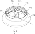
- FIG. 5 to 7 a second preferred embodiment of the centrifuge rotor 100 according to the invention is shown.
- This centrifuge rotor 100 differs only in relation to the design of the carrying handle 102 and the operating handle 104, while the remaining design of the lower part 106 and the lid 108, in particular in relation to the closure 109, is identical and will therefore not be explained again.
- the operating handle 104 and the carrying handle 102 are designed in such a way that they complement each other on the lower part 106 to form a uniform element 102, 104 when the lid 108 is closed.
- the carrying handle 102 is corresponding Fig. 6 with two oppositely arranged carrying handle elements 110a, 110b and respective undercuts 103 for gripping the carrying handle 102 and the operating handle 104 is designed with two oppositely arranged operating handle elements 112a, 112b and respective undercuts 105 for gripping the operating handle 104, which is in the closed state of the lid 108 the lower part 106 fit into each other, their contours being coordinated so that they complement each other rotationally symmetrically to form a uniform handle 114 with a uniform undercut 116.
- the actuating handle elements 112a, 112b protrude radially inwards with respect to an opening 120, this opening 120 being adapted to fit the hub 122 of the lower part 106.
- a disadvantage of this design is that the lid 108 can no longer be positioned freely on the lower part 106, but only with an angular alignment of 90° between the carrying handle 102 and the operating handle 104.
- the carrying handle 102 has the same color, for example black, as the rest of the lower part 106, while the operating handle 104 has the same color, for example red, as the rest of the lid 108.
- the spring element 36 is arranged in a second recess 38 of the hub 18, which is designed as an annular groove, and the spring element 36 engages in a first recess 34 which is arranged on the cover 14, it is clear that a reverse design can also be selected, in which the spring element is arranged on the cover and engages in a first recess arranged on the hub.
- the spring element 36 would remain in the annular groove 34 of the lid and the annular groove 38 of the hub 18 would form the first recess into which the spring element 346 engages during the closing process.
- the cross sections of the annular groove 34 and the annular groove 38 could simply be swapped.
- the present invention provides a centrifuge rotor 10, 100 in which the closure between the lower part of the centrifuge rotor 10, 100 and the lid 14, 108 has been improved so that genuine one-handed operation is possible.
- the closure can be closed and released again with just one hand.
- the closure is structurally simpler and can also be produced more cost-effectively.
Landscapes
- Engineering & Computer Science (AREA)
- General Engineering & Computer Science (AREA)
- Mechanical Engineering (AREA)
- Centrifugal Separators (AREA)
Applications Claiming Priority (2)
| Application Number | Priority Date | Filing Date | Title |
|---|---|---|---|
| DE102017130786.9A DE102017130786A1 (de) | 2017-12-20 | 2017-12-20 | Zentrifugenrotor |
| PCT/EP2018/085334 WO2019121581A1 (de) | 2017-12-20 | 2018-12-17 | Zentrifugenrotor |
Publications (2)
| Publication Number | Publication Date |
|---|---|
| EP3727700A1 EP3727700A1 (de) | 2020-10-28 |
| EP3727700B1 true EP3727700B1 (de) | 2024-04-03 |
Family
ID=64899309
Family Applications (1)
| Application Number | Title | Priority Date | Filing Date |
|---|---|---|---|
| EP18826285.1A Active EP3727700B1 (de) | 2017-12-20 | 2018-12-17 | Zentrifugenrotor |
Country Status (6)
Families Citing this family (6)
| Publication number | Priority date | Publication date | Assignee | Title |
|---|---|---|---|---|
| DE102014112501B4 (de) * | 2014-08-29 | 2017-07-27 | Andreas Hettich Gmbh & Co. Kg | Zentrifuge |
| DE102015113855A1 (de) * | 2015-08-20 | 2017-02-23 | Andreas Hettich Gmbh & Co. Kg | Rotor einer Zentrifuge |
| DE102015113854A1 (de) * | 2015-08-20 | 2017-02-23 | Andreas Hettich Gmbh & Co. Kg | Rotor einer Zentrifuge |
| DE102017130787A1 (de) * | 2017-12-20 | 2019-06-27 | Eppendorf Ag | Zentrifugenrotor |
| EP4180131A1 (de) | 2021-11-11 | 2023-05-17 | Eppendorf SE | Zentrifugenrotor, rotordeckel und rotorunterteil |
| EP4180132A1 (de) | 2021-11-11 | 2023-05-17 | Eppendorf SE | Zentrifugenrotor, rotordeckel und rotorunterteil |
Family Cites Families (13)
| Publication number | Priority date | Publication date | Assignee | Title |
|---|---|---|---|---|
| JPH05345149A (ja) * | 1992-06-12 | 1993-12-27 | Hitachi Koki Co Ltd | 遠心分離機用ロータ |
| US5362300A (en) * | 1993-05-27 | 1994-11-08 | E. I. Du Pont De Nemours And Company | Shell-type centrifuge rotor |
| DE4326231A1 (de) * | 1993-08-05 | 1995-02-09 | Hettich Andreas Fa | Rotorkupplung für einen Zentrifugenrotor |
| US6286838B1 (en) * | 1997-09-15 | 2001-09-11 | Kendro Labatory Products Gmbh | Process and device for sealing a rotor for laboratory centrifuges |
| AU2002362011A1 (en) * | 2001-11-21 | 2003-06-10 | Bal Seal Engineering Co., Inc. | Connector with radial spring |
| US8167285B2 (en) * | 2003-06-04 | 2012-05-01 | Bal Seal Engineering Co., Inc. | Spring latching connectors radially and axially mounted |
| DE102005014218B4 (de) * | 2005-03-29 | 2008-03-06 | Thermo Electron Led Gmbh | Befestigungsvorrichtung eines Deckels für einen Zentrifugenrotor |
| JP2007152209A (ja) * | 2005-12-02 | 2007-06-21 | Kubota Seisakusho:Kk | 遠心分離機用ロータおよび遠心分離機 |
| JP4809474B2 (ja) * | 2006-05-23 | 2011-11-09 | エッペンドルフ アクチエンゲゼルシャフト | 遠心ロータの閉鎖用カバー |
| JP5212907B2 (ja) * | 2008-12-16 | 2013-06-19 | 日立工機株式会社 | 遠心分離機 |
| JP6136509B2 (ja) * | 2012-05-23 | 2017-05-31 | 日立工機株式会社 | 遠心分離機および遠心分離機用ロータおよび遠心分離機用試料容器 |
| DE202012008062U1 (de) * | 2012-08-24 | 2012-10-01 | Sigma Laborzentrifugen Gmbh | Rotor für eine Laborzentrifuge |
| DE102014112501B4 (de) * | 2014-08-29 | 2017-07-27 | Andreas Hettich Gmbh & Co. Kg | Zentrifuge |
-
2017
- 2017-12-20 DE DE102017130786.9A patent/DE102017130786A1/de not_active Withdrawn
-
2018
- 2018-12-17 US US16/955,367 patent/US20200406270A1/en not_active Abandoned
- 2018-12-17 CN CN201880087776.8A patent/CN111655379B/zh active Active
- 2018-12-17 WO PCT/EP2018/085334 patent/WO2019121581A1/de unknown
- 2018-12-17 JP JP2020534270A patent/JP7202384B2/ja active Active
- 2018-12-17 EP EP18826285.1A patent/EP3727700B1/de active Active
Also Published As
| Publication number | Publication date |
|---|---|
| DE102017130786A1 (de) | 2019-06-27 |
| CN111655379B (zh) | 2022-08-30 |
| CN111655379A (zh) | 2020-09-11 |
| JP7202384B2 (ja) | 2023-01-11 |
| JP2021506577A (ja) | 2021-02-22 |
| WO2019121581A1 (de) | 2019-06-27 |
| US20200406270A1 (en) | 2020-12-31 |
| EP3727700A1 (de) | 2020-10-28 |
Similar Documents
| Publication | Publication Date | Title |
|---|---|---|
| EP3727700B1 (de) | Zentrifugenrotor | |
| EP3727699B1 (de) | Zentrifugenrotor | |
| DE69311299T2 (de) | Handhebel für zentrifugenrotor und deckel | |
| DE69913483T2 (de) | Vorrichtung zum verriegeln/entriegeln eines dampfdruck-kochtopfs mit bajonettverschluss | |
| EP0190593A2 (de) | Verschlusskappen für Zweikomponentenpackungssysteme | |
| EP1933985B1 (de) | Kugelmühle mit rastmitteln | |
| EP0115774A1 (de) | Federnspanner | |
| DE2907001A1 (de) | Zentrifugenrotoraggregat | |
| DE202014101096U1 (de) | Ventiloberteil | |
| WO2007068011A1 (de) | Universelle verschlussvorrichtung | |
| DE102011008975A1 (de) | Schraubverschlussöffner | |
| DE69010589T2 (de) | Zentrifugalapparat mit einer Vorrichtung zum Schliessen des Behälters einer Blutzentrifugalkammer. | |
| EP0111292A1 (de) | Deckelknopf mit steuerbarem Dampfauslass | |
| EP2301885B9 (de) | Vorrichtung zum Verschließen von Gefäßen mit einem Verschluss | |
| EP2387542A2 (de) | Verschliesserkopf für behälterverschliessmaschinen sowie behälterverschliessmaschine | |
| DE2121739A1 (de) | Sicherheits-Kappenverschluß für Gefäße mit Hals | |
| DE69603147T2 (de) | Manipulierbarer Behälter aus Kunststoff | |
| WO2017118603A1 (de) | Flaschenverschluss | |
| DE3427429C1 (de) | Isolierkanne | |
| EP4180132A1 (de) | Zentrifugenrotor, rotordeckel und rotorunterteil | |
| DE811919C (de) | Deckelverschluss | |
| DE908580C (de) | Verschlussvorrichtung fuer Flaschen und andere Behaelter | |
| DE102017001839B3 (de) | Lösbarer Verschluss und Flasche mit einem Kronenmundstück | |
| DE2024598A1 (de) | Verschluß für Behälter | |
| EP4431415A1 (de) | Anordnung aus einem aussenbehälter mit einem darin angeordneten innenbehälter und verfahren zum öffnen und zum herstellen einer anordnung |
Legal Events
| Date | Code | Title | Description |
|---|---|---|---|
| STAA | Information on the status of an ep patent application or granted ep patent |
Free format text: STATUS: UNKNOWN |
|
| STAA | Information on the status of an ep patent application or granted ep patent |
Free format text: STATUS: THE INTERNATIONAL PUBLICATION HAS BEEN MADE |
|
| PUAI | Public reference made under article 153(3) epc to a published international application that has entered the european phase |
Free format text: ORIGINAL CODE: 0009012 |
|
| STAA | Information on the status of an ep patent application or granted ep patent |
Free format text: STATUS: REQUEST FOR EXAMINATION WAS MADE |
|
| 17P | Request for examination filed |
Effective date: 20200714 |
|
| AK | Designated contracting states |
Kind code of ref document: A1 Designated state(s): AL AT BE BG CH CY CZ DE DK EE ES FI FR GB GR HR HU IE IS IT LI LT LU LV MC MK MT NL NO PL PT RO RS SE SI SK SM TR |
|
| AX | Request for extension of the european patent |
Extension state: BA ME |
|
| DAV | Request for validation of the european patent (deleted) | ||
| DAX | Request for extension of the european patent (deleted) | ||
| RAP3 | Party data changed (applicant data changed or rights of an application transferred) |
Owner name: EPPENDORF SE |
|
| GRAP | Despatch of communication of intention to grant a patent |
Free format text: ORIGINAL CODE: EPIDOSNIGR1 |
|
| STAA | Information on the status of an ep patent application or granted ep patent |
Free format text: STATUS: GRANT OF PATENT IS INTENDED |
|
| RIC1 | Information provided on ipc code assigned before grant |
Ipc: F16B 21/18 20060101ALI20231103BHEP Ipc: B04B 7/02 20060101ALI20231103BHEP Ipc: B04B 7/08 20060101ALI20231103BHEP Ipc: B04B 5/04 20060101AFI20231103BHEP |
|
| INTG | Intention to grant announced |
Effective date: 20231123 |
|
| GRAS | Grant fee paid |
Free format text: ORIGINAL CODE: EPIDOSNIGR3 |
|
| GRAA | (expected) grant |
Free format text: ORIGINAL CODE: 0009210 |
|
| STAA | Information on the status of an ep patent application or granted ep patent |
Free format text: STATUS: THE PATENT HAS BEEN GRANTED |
|
| AK | Designated contracting states |
Kind code of ref document: B1 Designated state(s): AL AT BE BG CH CY CZ DE DK EE ES FI FR GB GR HR HU IE IS IT LI LT LU LV MC MK MT NL NO PL PT RO RS SE SI SK SM TR |
|
| REG | Reference to a national code |
Ref country code: GB Ref legal event code: FG4D Free format text: NOT ENGLISH |
|
| REG | Reference to a national code |
Ref country code: CH Ref legal event code: EP |
|
| REG | Reference to a national code |
Ref country code: IE Ref legal event code: FG4D Free format text: LANGUAGE OF EP DOCUMENT: GERMAN |
|
| REG | Reference to a national code |
Ref country code: DE Ref legal event code: R096 Ref document number: 502018014394 Country of ref document: DE |
|
| REG | Reference to a national code |
Ref country code: LT Ref legal event code: MG9D |
|
| REG | Reference to a national code |
Ref country code: NL Ref legal event code: MP Effective date: 20240403 |
|
| PG25 | Lapsed in a contracting state [announced via postgrant information from national office to epo] |
Ref country code: NL Free format text: LAPSE BECAUSE OF FAILURE TO SUBMIT A TRANSLATION OF THE DESCRIPTION OR TO PAY THE FEE WITHIN THE PRESCRIBED TIME-LIMIT Effective date: 20240403 |
|
| PG25 | Lapsed in a contracting state [announced via postgrant information from national office to epo] |
Ref country code: NL Free format text: LAPSE BECAUSE OF FAILURE TO SUBMIT A TRANSLATION OF THE DESCRIPTION OR TO PAY THE FEE WITHIN THE PRESCRIBED TIME-LIMIT Effective date: 20240403 |
|
| PG25 | Lapsed in a contracting state [announced via postgrant information from national office to epo] |
Ref country code: IS Free format text: LAPSE BECAUSE OF FAILURE TO SUBMIT A TRANSLATION OF THE DESCRIPTION OR TO PAY THE FEE WITHIN THE PRESCRIBED TIME-LIMIT Effective date: 20240803 |
|
| PG25 | Lapsed in a contracting state [announced via postgrant information from national office to epo] |
Ref country code: BG Free format text: LAPSE BECAUSE OF FAILURE TO SUBMIT A TRANSLATION OF THE DESCRIPTION OR TO PAY THE FEE WITHIN THE PRESCRIBED TIME-LIMIT Effective date: 20240403 |
|
| PG25 | Lapsed in a contracting state [announced via postgrant information from national office to epo] |
Ref country code: FI Free format text: LAPSE BECAUSE OF FAILURE TO SUBMIT A TRANSLATION OF THE DESCRIPTION OR TO PAY THE FEE WITHIN THE PRESCRIBED TIME-LIMIT Effective date: 20240403 Ref country code: HR Free format text: LAPSE BECAUSE OF FAILURE TO SUBMIT A TRANSLATION OF THE DESCRIPTION OR TO PAY THE FEE WITHIN THE PRESCRIBED TIME-LIMIT Effective date: 20240403 |
|
| PG25 | Lapsed in a contracting state [announced via postgrant information from national office to epo] |
Ref country code: GR Free format text: LAPSE BECAUSE OF FAILURE TO SUBMIT A TRANSLATION OF THE DESCRIPTION OR TO PAY THE FEE WITHIN THE PRESCRIBED TIME-LIMIT Effective date: 20240704 |
|
| PG25 | Lapsed in a contracting state [announced via postgrant information from national office to epo] |
Ref country code: PT Free format text: LAPSE BECAUSE OF FAILURE TO SUBMIT A TRANSLATION OF THE DESCRIPTION OR TO PAY THE FEE WITHIN THE PRESCRIBED TIME-LIMIT Effective date: 20240805 |
|
| PG25 | Lapsed in a contracting state [announced via postgrant information from national office to epo] |
Ref country code: ES Free format text: LAPSE BECAUSE OF FAILURE TO SUBMIT A TRANSLATION OF THE DESCRIPTION OR TO PAY THE FEE WITHIN THE PRESCRIBED TIME-LIMIT Effective date: 20240403 |
|
| PG25 | Lapsed in a contracting state [announced via postgrant information from national office to epo] |
Ref country code: CZ Free format text: LAPSE BECAUSE OF FAILURE TO SUBMIT A TRANSLATION OF THE DESCRIPTION OR TO PAY THE FEE WITHIN THE PRESCRIBED TIME-LIMIT Effective date: 20240403 |
|
| PG25 | Lapsed in a contracting state [announced via postgrant information from national office to epo] |
Ref country code: PL Free format text: LAPSE BECAUSE OF FAILURE TO SUBMIT A TRANSLATION OF THE DESCRIPTION OR TO PAY THE FEE WITHIN THE PRESCRIBED TIME-LIMIT Effective date: 20240403 |
|
| PG25 | Lapsed in a contracting state [announced via postgrant information from national office to epo] |
Ref country code: LV Free format text: LAPSE BECAUSE OF FAILURE TO SUBMIT A TRANSLATION OF THE DESCRIPTION OR TO PAY THE FEE WITHIN THE PRESCRIBED TIME-LIMIT Effective date: 20240403 |
|
| PG25 | Lapsed in a contracting state [announced via postgrant information from national office to epo] |
Ref country code: PT Free format text: LAPSE BECAUSE OF FAILURE TO SUBMIT A TRANSLATION OF THE DESCRIPTION OR TO PAY THE FEE WITHIN THE PRESCRIBED TIME-LIMIT Effective date: 20240805 Ref country code: PL Free format text: LAPSE BECAUSE OF FAILURE TO SUBMIT A TRANSLATION OF THE DESCRIPTION OR TO PAY THE FEE WITHIN THE PRESCRIBED TIME-LIMIT Effective date: 20240403 Ref country code: NO Free format text: LAPSE BECAUSE OF FAILURE TO SUBMIT A TRANSLATION OF THE DESCRIPTION OR TO PAY THE FEE WITHIN THE PRESCRIBED TIME-LIMIT Effective date: 20240703 Ref country code: LV Free format text: LAPSE BECAUSE OF FAILURE TO SUBMIT A TRANSLATION OF THE DESCRIPTION OR TO PAY THE FEE WITHIN THE PRESCRIBED TIME-LIMIT Effective date: 20240403 Ref country code: IS Free format text: LAPSE BECAUSE OF FAILURE TO SUBMIT A TRANSLATION OF THE DESCRIPTION OR TO PAY THE FEE WITHIN THE PRESCRIBED TIME-LIMIT Effective date: 20240803 Ref country code: HR Free format text: LAPSE BECAUSE OF FAILURE TO SUBMIT A TRANSLATION OF THE DESCRIPTION OR TO PAY THE FEE WITHIN THE PRESCRIBED TIME-LIMIT Effective date: 20240403 Ref country code: GR Free format text: LAPSE BECAUSE OF FAILURE TO SUBMIT A TRANSLATION OF THE DESCRIPTION OR TO PAY THE FEE WITHIN THE PRESCRIBED TIME-LIMIT Effective date: 20240704 Ref country code: FI Free format text: LAPSE BECAUSE OF FAILURE TO SUBMIT A TRANSLATION OF THE DESCRIPTION OR TO PAY THE FEE WITHIN THE PRESCRIBED TIME-LIMIT Effective date: 20240403 Ref country code: ES Free format text: LAPSE BECAUSE OF FAILURE TO SUBMIT A TRANSLATION OF THE DESCRIPTION OR TO PAY THE FEE WITHIN THE PRESCRIBED TIME-LIMIT Effective date: 20240403 Ref country code: CZ Free format text: LAPSE BECAUSE OF FAILURE TO SUBMIT A TRANSLATION OF THE DESCRIPTION OR TO PAY THE FEE WITHIN THE PRESCRIBED TIME-LIMIT Effective date: 20240403 Ref country code: BG Free format text: LAPSE BECAUSE OF FAILURE TO SUBMIT A TRANSLATION OF THE DESCRIPTION OR TO PAY THE FEE WITHIN THE PRESCRIBED TIME-LIMIT Effective date: 20240403 Ref country code: RS Free format text: LAPSE BECAUSE OF FAILURE TO SUBMIT A TRANSLATION OF THE DESCRIPTION OR TO PAY THE FEE WITHIN THE PRESCRIBED TIME-LIMIT Effective date: 20240703 |
|
| REG | Reference to a national code |
Ref country code: DE Ref legal event code: R097 Ref document number: 502018014394 Country of ref document: DE |
|
| PGFP | Annual fee paid to national office [announced via postgrant information from national office to epo] |
Ref country code: DE Payment date: 20241210 Year of fee payment: 7 |
|
| PG25 | Lapsed in a contracting state [announced via postgrant information from national office to epo] |
Ref country code: DK Free format text: LAPSE BECAUSE OF FAILURE TO SUBMIT A TRANSLATION OF THE DESCRIPTION OR TO PAY THE FEE WITHIN THE PRESCRIBED TIME-LIMIT Effective date: 20240403 |
|
| PG25 | Lapsed in a contracting state [announced via postgrant information from national office to epo] |
Ref country code: EE Free format text: LAPSE BECAUSE OF FAILURE TO SUBMIT A TRANSLATION OF THE DESCRIPTION OR TO PAY THE FEE WITHIN THE PRESCRIBED TIME-LIMIT Effective date: 20240403 |
|
| PG25 | Lapsed in a contracting state [announced via postgrant information from national office to epo] |
Ref country code: RO Free format text: LAPSE BECAUSE OF FAILURE TO SUBMIT A TRANSLATION OF THE DESCRIPTION OR TO PAY THE FEE WITHIN THE PRESCRIBED TIME-LIMIT Effective date: 20240403 Ref country code: SK Free format text: LAPSE BECAUSE OF FAILURE TO SUBMIT A TRANSLATION OF THE DESCRIPTION OR TO PAY THE FEE WITHIN THE PRESCRIBED TIME-LIMIT Effective date: 20240403 |
|
| PG25 | Lapsed in a contracting state [announced via postgrant information from national office to epo] |
Ref country code: SM Free format text: LAPSE BECAUSE OF FAILURE TO SUBMIT A TRANSLATION OF THE DESCRIPTION OR TO PAY THE FEE WITHIN THE PRESCRIBED TIME-LIMIT Effective date: 20240403 |
|
| PG25 | Lapsed in a contracting state [announced via postgrant information from national office to epo] |
Ref country code: SM Free format text: LAPSE BECAUSE OF FAILURE TO SUBMIT A TRANSLATION OF THE DESCRIPTION OR TO PAY THE FEE WITHIN THE PRESCRIBED TIME-LIMIT Effective date: 20240403 Ref country code: SK Free format text: LAPSE BECAUSE OF FAILURE TO SUBMIT A TRANSLATION OF THE DESCRIPTION OR TO PAY THE FEE WITHIN THE PRESCRIBED TIME-LIMIT Effective date: 20240403 Ref country code: RO Free format text: LAPSE BECAUSE OF FAILURE TO SUBMIT A TRANSLATION OF THE DESCRIPTION OR TO PAY THE FEE WITHIN THE PRESCRIBED TIME-LIMIT Effective date: 20240403 Ref country code: EE Free format text: LAPSE BECAUSE OF FAILURE TO SUBMIT A TRANSLATION OF THE DESCRIPTION OR TO PAY THE FEE WITHIN THE PRESCRIBED TIME-LIMIT Effective date: 20240403 Ref country code: DK Free format text: LAPSE BECAUSE OF FAILURE TO SUBMIT A TRANSLATION OF THE DESCRIPTION OR TO PAY THE FEE WITHIN THE PRESCRIBED TIME-LIMIT Effective date: 20240403 |
|
| PLBE | No opposition filed within time limit |
Free format text: ORIGINAL CODE: 0009261 |
|
| STAA | Information on the status of an ep patent application or granted ep patent |
Free format text: STATUS: NO OPPOSITION FILED WITHIN TIME LIMIT |
|
| 26N | No opposition filed |
Effective date: 20250106 |
|
| PG25 | Lapsed in a contracting state [announced via postgrant information from national office to epo] |
Ref country code: SI Free format text: LAPSE BECAUSE OF FAILURE TO SUBMIT A TRANSLATION OF THE DESCRIPTION OR TO PAY THE FEE WITHIN THE PRESCRIBED TIME-LIMIT Effective date: 20240403 |
|
| PG25 | Lapsed in a contracting state [announced via postgrant information from national office to epo] |
Ref country code: MC Free format text: LAPSE BECAUSE OF FAILURE TO SUBMIT A TRANSLATION OF THE DESCRIPTION OR TO PAY THE FEE WITHIN THE PRESCRIBED TIME-LIMIT Effective date: 20240403 |
|
| REG | Reference to a national code |
Ref country code: CH Ref legal event code: PL |
|
| PG25 | Lapsed in a contracting state [announced via postgrant information from national office to epo] |
Ref country code: LU Free format text: LAPSE BECAUSE OF NON-PAYMENT OF DUE FEES Effective date: 20241217 |
|
| GBPC | Gb: european patent ceased through non-payment of renewal fee |
Effective date: 20241217 |