EP3725606A1 - Battery charging and swapping station - Google Patents
Battery charging and swapping station Download PDFInfo
- Publication number
- EP3725606A1 EP3725606A1 EP18888456.3A EP18888456A EP3725606A1 EP 3725606 A1 EP3725606 A1 EP 3725606A1 EP 18888456 A EP18888456 A EP 18888456A EP 3725606 A1 EP3725606 A1 EP 3725606A1
- Authority
- EP
- European Patent Office
- Prior art keywords
- battery
- unit
- swap
- vehicle
- charging
- Prior art date
- Legal status (The legal status is an assumption and is not a legal conclusion. Google has not performed a legal analysis and makes no representation as to the accuracy of the status listed.)
- Withdrawn
Links
- 238000007600 charging Methods 0.000 title claims abstract description 121
- 230000007246 mechanism Effects 0.000 claims description 151
- 238000012546 transfer Methods 0.000 claims description 97
- 230000005540 biological transmission Effects 0.000 claims description 47
- 238000013519 translation Methods 0.000 claims description 21
- 230000032258 transport Effects 0.000 description 15
- 238000010586 diagram Methods 0.000 description 14
- 238000009434 installation Methods 0.000 description 8
- 238000000034 method Methods 0.000 description 8
- 230000008569 process Effects 0.000 description 7
- 230000009471 action Effects 0.000 description 3
- 238000010276 construction Methods 0.000 description 2
- 238000013461 design Methods 0.000 description 2
- 238000006467 substitution reaction Methods 0.000 description 2
- 238000004891 communication Methods 0.000 description 1
- 238000001816 cooling Methods 0.000 description 1
- 238000011161 development Methods 0.000 description 1
- 238000007599 discharging Methods 0.000 description 1
- 238000012423 maintenance Methods 0.000 description 1
Images


Classifications
-
- B—PERFORMING OPERATIONS; TRANSPORTING
- B60—VEHICLES IN GENERAL
- B60L—PROPULSION OF ELECTRICALLY-PROPELLED VEHICLES; SUPPLYING ELECTRIC POWER FOR AUXILIARY EQUIPMENT OF ELECTRICALLY-PROPELLED VEHICLES; ELECTRODYNAMIC BRAKE SYSTEMS FOR VEHICLES IN GENERAL; MAGNETIC SUSPENSION OR LEVITATION FOR VEHICLES; MONITORING OPERATING VARIABLES OF ELECTRICALLY-PROPELLED VEHICLES; ELECTRIC SAFETY DEVICES FOR ELECTRICALLY-PROPELLED VEHICLES
- B60L53/00—Methods of charging batteries, specially adapted for electric vehicles; Charging stations or on-board charging equipment therefor; Exchange of energy storage elements in electric vehicles
- B60L53/30—Constructional details of charging stations
- B60L53/35—Means for automatic or assisted adjustment of the relative position of charging devices and vehicles
- B60L53/36—Means for automatic or assisted adjustment of the relative position of charging devices and vehicles by positioning the vehicle
-
- B—PERFORMING OPERATIONS; TRANSPORTING
- B60—VEHICLES IN GENERAL
- B60K—ARRANGEMENT OR MOUNTING OF PROPULSION UNITS OR OF TRANSMISSIONS IN VEHICLES; ARRANGEMENT OR MOUNTING OF PLURAL DIVERSE PRIME-MOVERS IN VEHICLES; AUXILIARY DRIVES FOR VEHICLES; INSTRUMENTATION OR DASHBOARDS FOR VEHICLES; ARRANGEMENTS IN CONNECTION WITH COOLING, AIR INTAKE, GAS EXHAUST OR FUEL SUPPLY OF PROPULSION UNITS IN VEHICLES
- B60K1/00—Arrangement or mounting of electrical propulsion units
- B60K1/04—Arrangement or mounting of electrical propulsion units of the electric storage means for propulsion
-
- B—PERFORMING OPERATIONS; TRANSPORTING
- B60—VEHICLES IN GENERAL
- B60L—PROPULSION OF ELECTRICALLY-PROPELLED VEHICLES; SUPPLYING ELECTRIC POWER FOR AUXILIARY EQUIPMENT OF ELECTRICALLY-PROPELLED VEHICLES; ELECTRODYNAMIC BRAKE SYSTEMS FOR VEHICLES IN GENERAL; MAGNETIC SUSPENSION OR LEVITATION FOR VEHICLES; MONITORING OPERATING VARIABLES OF ELECTRICALLY-PROPELLED VEHICLES; ELECTRIC SAFETY DEVICES FOR ELECTRICALLY-PROPELLED VEHICLES
- B60L53/00—Methods of charging batteries, specially adapted for electric vehicles; Charging stations or on-board charging equipment therefor; Exchange of energy storage elements in electric vehicles
- B60L53/30—Constructional details of charging stations
-
- B—PERFORMING OPERATIONS; TRANSPORTING
- B60—VEHICLES IN GENERAL
- B60L—PROPULSION OF ELECTRICALLY-PROPELLED VEHICLES; SUPPLYING ELECTRIC POWER FOR AUXILIARY EQUIPMENT OF ELECTRICALLY-PROPELLED VEHICLES; ELECTRODYNAMIC BRAKE SYSTEMS FOR VEHICLES IN GENERAL; MAGNETIC SUSPENSION OR LEVITATION FOR VEHICLES; MONITORING OPERATING VARIABLES OF ELECTRICALLY-PROPELLED VEHICLES; ELECTRIC SAFETY DEVICES FOR ELECTRICALLY-PROPELLED VEHICLES
- B60L53/00—Methods of charging batteries, specially adapted for electric vehicles; Charging stations or on-board charging equipment therefor; Exchange of energy storage elements in electric vehicles
- B60L53/80—Exchanging energy storage elements, e.g. removable batteries
-
- B—PERFORMING OPERATIONS; TRANSPORTING
- B60—VEHICLES IN GENERAL
- B60K—ARRANGEMENT OR MOUNTING OF PROPULSION UNITS OR OF TRANSMISSIONS IN VEHICLES; ARRANGEMENT OR MOUNTING OF PLURAL DIVERSE PRIME-MOVERS IN VEHICLES; AUXILIARY DRIVES FOR VEHICLES; INSTRUMENTATION OR DASHBOARDS FOR VEHICLES; ARRANGEMENTS IN CONNECTION WITH COOLING, AIR INTAKE, GAS EXHAUST OR FUEL SUPPLY OF PROPULSION UNITS IN VEHICLES
- B60K1/00—Arrangement or mounting of electrical propulsion units
- B60K1/04—Arrangement or mounting of electrical propulsion units of the electric storage means for propulsion
- B60K2001/0455—Removal or replacement of the energy storages
- B60K2001/0472—Removal or replacement of the energy storages from below
-
- B—PERFORMING OPERATIONS; TRANSPORTING
- B60—VEHICLES IN GENERAL
- B60S—SERVICING, CLEANING, REPAIRING, SUPPORTING, LIFTING, OR MANOEUVRING OF VEHICLES, NOT OTHERWISE PROVIDED FOR
- B60S5/00—Servicing, maintaining, repairing, or refitting of vehicles
- B60S5/06—Supplying batteries to, or removing batteries from, vehicles
-
- Y—GENERAL TAGGING OF NEW TECHNOLOGICAL DEVELOPMENTS; GENERAL TAGGING OF CROSS-SECTIONAL TECHNOLOGIES SPANNING OVER SEVERAL SECTIONS OF THE IPC; TECHNICAL SUBJECTS COVERED BY FORMER USPC CROSS-REFERENCE ART COLLECTIONS [XRACs] AND DIGESTS
- Y02—TECHNOLOGIES OR APPLICATIONS FOR MITIGATION OR ADAPTATION AGAINST CLIMATE CHANGE
- Y02T—CLIMATE CHANGE MITIGATION TECHNOLOGIES RELATED TO TRANSPORTATION
- Y02T10/00—Road transport of goods or passengers
- Y02T10/60—Other road transportation technologies with climate change mitigation effect
- Y02T10/70—Energy storage systems for electromobility, e.g. batteries
-
- Y—GENERAL TAGGING OF NEW TECHNOLOGICAL DEVELOPMENTS; GENERAL TAGGING OF CROSS-SECTIONAL TECHNOLOGIES SPANNING OVER SEVERAL SECTIONS OF THE IPC; TECHNICAL SUBJECTS COVERED BY FORMER USPC CROSS-REFERENCE ART COLLECTIONS [XRACs] AND DIGESTS
- Y02—TECHNOLOGIES OR APPLICATIONS FOR MITIGATION OR ADAPTATION AGAINST CLIMATE CHANGE
- Y02T—CLIMATE CHANGE MITIGATION TECHNOLOGIES RELATED TO TRANSPORTATION
- Y02T10/00—Road transport of goods or passengers
- Y02T10/60—Other road transportation technologies with climate change mitigation effect
- Y02T10/7072—Electromobility specific charging systems or methods for batteries, ultracapacitors, supercapacitors or double-layer capacitors
-
- Y—GENERAL TAGGING OF NEW TECHNOLOGICAL DEVELOPMENTS; GENERAL TAGGING OF CROSS-SECTIONAL TECHNOLOGIES SPANNING OVER SEVERAL SECTIONS OF THE IPC; TECHNICAL SUBJECTS COVERED BY FORMER USPC CROSS-REFERENCE ART COLLECTIONS [XRACs] AND DIGESTS
- Y02—TECHNOLOGIES OR APPLICATIONS FOR MITIGATION OR ADAPTATION AGAINST CLIMATE CHANGE
- Y02T—CLIMATE CHANGE MITIGATION TECHNOLOGIES RELATED TO TRANSPORTATION
- Y02T90/00—Enabling technologies or technologies with a potential or indirect contribution to GHG emissions mitigation
- Y02T90/10—Technologies relating to charging of electric vehicles
- Y02T90/12—Electric charging stations
Definitions
- the invention relates to the field of battery swapping, and in particular to a battery charging and swap station.
- the current mainstream electric energy replenishment solutions include a charging solution and a battery swapping solution.
- the battery swapping solution can swap a traction battery in a very short time and does not significantly affect the service life of the traction battery, and is therefore one of the main development directions of electric energy replenishment.
- the battery swapping solution is generally completed in a battery charging and swap station.
- the battery charging and swap station is internally provided with a battery rack for storing batteries and a battery swap platform as well as a battery swap robot, such as a Rail Guided Vehicle (RGV) or an Auto Guided Vehicle (AGV), for carrying a fresh/used traction battery between the battery rack and the battery swap platform.
- a battery swap robot such as a Rail Guided Vehicle (RGV) or an Auto Guided Vehicle (AGV) for carrying a fresh/used traction battery between the battery rack and the battery swap platform.
- the battery swap robot implements the transportation of the battery and the swapping of a battery of the electric vehicle by means of reciprocating between the battery rack and the battery swap platform.
- the battery swapping solution has many advantages mentioned above, certain problems inevitably exist.
- the height of the battery swap robot is relatively high such that the battery swap platform needs to be provided with a dedicated lifting device to raise the electric vehicle to a higher height before the battery swap robot enter the bottom of the vehicle for battery swapping.
- this configuration also requires that during the battery swapping, the driver (a passenger or a battery swap service personnel) needs to park the vehicle, gets off the vehicle and waits until the end of the battery swap process, and then gets on the vehicle and drives same away. This process is proper for safety reasons, but results in a very poor user experience.
- a dedicated rail or guide line needs to be laid in the battery charging and swap station, and the rail or the guide line needs to occupy two regions, i.e. the battery rack and the battery swap platform, which fails to implement modular installation and transportation of the battery charging and swap station and causes inconveniences in transportation and installation to the manufacturer of the battery charging and swap station.
- the battery charging and swap station comprises a battery charging and storage module and a battery swap platform module, wherein the battery charging and storage module stores a plurality of batteries, and the battery charging and storage module is configured to dock with and exchange a battery with the battery swap platform module; and wherein the battery swap platform module is configured to transport the battery and to swap a battery of a vehicle.
- the battery swap platform module comprises: a parking platform configured to position a vehicle parked thereon; a locking/unlocking unit configured to remove a used battery from the vehicle and install a fresh battery to the vehicle; and a battery transportation unit configured to transport the used battery removed by the locking/unlocking unit to the battery charging and storage module and to receive the fresh battery from the battery charging and storage module and transport the fresh battery to the locking/unlocking unit.
- the battery transportation unit is further configured to transport the used battery removed by the locking/unlocking unit to the battery charging and storage module without lifting the vehicle, and to receive the fresh battery from the battery charging and storage module and transport the fresh battery to the locking/unlocking unit.
- the battery transportation unit comprises a first driving mechanism and a first transmission mechanism, wherein the first driving mechanism is able to drive the first transmission mechanism to move, and the first transmission mechanism is able to carry the battery.
- the locking/unlocking unit comprises a hoisting mechanism and a locking/unlocking mechanism, wherein the hoisting mechanism is able to hoist the locking/unlocking mechanism to a battery swap position, and the locking/unlocking mechanism is able to lock/unlock the battery at the battery swap position.
- the locking/unlocking unit is further configured with a translation unit, wherein the translation unit enables the locking/unlocking unit to move in forward/backward direction of the vehicle.
- the parking platform is provided with a first positioning mechanism and a second positioning mechanism, wherein the first positioning mechanism enables the vehicle to be positioned in a forward/backward direction of the vehicle, and the second positioning mechanism enables the vehicle to be positioned in a width direction of the vehicle.
- the first positioning mechanism comprises a set of V-shaped rollers and a set of I-shaped rollers, wherein the set of V-shaped rollers enables front/rear wheels of the vehicle to be embedded therein, and the set of V-shaped rollers allows the front/rear wheels of the vehicle to move in the width direction; and the set of I-shaped rollers respectively allows the rear/front wheels of the vehicle to be supported thereon and to move in the width direction.
- the second positioning mechanism comprises a front wheel centring push/pull rod and/or a rear wheel centring push/pull rod, wherein the front wheel centring push/pull rod and/or the rear wheel centring push/pull rod enable the vehicle to be positioned in the width direction by means of pushing/pulling the front/rear wheels of the vehicle.
- the battery swap platform module further comprises a vehicle lifting unit and/or a leveling unit, wherein the vehicle lifting unit is able to raise the vehicle parked on the parking platform by a preset distance; and wherein the leveling unit is able to adjust the degree of parallelism of the vehicle and the parking platform.
- the battery charging and storage module comprises a battery storage device and a battery transfer device, wherein the battery storage device stores a plurality of batteries, and the battery storage device is configured to dock with and exchange the battery with the battery transfer device; and the battery transfer device is configured to receive the used battery from the battery transportation unit and transfer the used battery to the battery storage device, and to receive the fresh battery from the battery storage device and transfer the fresh battery to the battery transportation unit.
- the battery storage device further comprise a plurality of battery rack units, wherein each of the battery rack units is provided with a first battery transfer unit, and the first battery transfer unit is configured to enable the battery to enter/exit the battery rack unit.
- the first battery transfer unit comprises a second driving mechanism and a second transmission mechanism, wherein the second driving mechanism is able to drive the second transmission mechanism to move, and the second transmission mechanism is able to carry the battery.
- the battery transfer device comprises a battery lifting unit and at least one second battery transfer unit, wherein the battery lifting unit is configured to enable the at least one second battery transfer unit to ascend/descend, and the second battery transfer unit is configured to enable the battery to enter/exit the battery transfer device.
- the battery transfer device comprises two second battery transfer units, wherein the two second battery transfer units are configured in such a way that: while or after one of the second battery transfer units receives/transfers the used battery, the other one of the second battery transfer units is able to respectively transfer/receive the fresh battery.
- the battery lifting unit comprises a third driving mechanism and a third transmission mechanism, wherein the third driving mechanism is able to drive the third transmission mechanism to ascend/descend, and the third transmission mechanism is connected to the at least one second battery transfer unit.
- the second battery transfer unit comprises a fourth driving mechanism and a fourth transmission mechanism, wherein the fourth driving mechanism is able to drive the fourth transmission mechanism to move, and the fourth transmission mechanism is able to carry the battery.
- the battery charging and swap station comprises the battery charging and storage module and the battery swap platform module, and comprises no battery swap robot.
- the battery charging and storage module is configured to dock with and exchange the battery with the battery swap platform module
- the battery swap platform module is configured to transport the battery and to swap the battery of a vehicle.
- the battery swap platform module further comprises a parking platform, a locking/unlocking unit and a battery transportation unit, wherein the battery transportation unit is further configured to transport the used battery removed by the locking/unlocking unit to the battery charging and storage module without lifting the vehicle, and to receive the fresh battery from the battery charging and storage module and transport the fresh battery to the locking/unlocking unit.
- the battery charging and swap station of the invention allows to complete the battery swapping without providing the battery swap robot and a vehicle lifting mechanism.
- This configuration eliminates the vehicle lifting process during the battery swapping, speeds up the cycle of battery swapping, and allows to complete the battery swapping without the driver getting off from the vehicle.
- the structure of the battery charging and swap station may be greatly simplified, that is, the arrangement of the battery swap robot,the rail, and the vehicle lifting mechanism is simplified, such that modular transportation and installation of the overall station is allowed with the battery swap platform module and the battery charging and storage module as two separate modules.
- the battery charging and swap station of the invention solves the problems of poor battery swap experience and inconvenient transportation and installation of the existing battery charging and swap stations, realizes miniaturization and monolithic assembly and transportation of the battery charging and swap station, reduces civil work for the battery charging and swap station, facilitates the installation and setup of the charging and replacing power station in a city, and improves battery swap efficiency and the battery swap experience.
- Battery charging and storage module 11. Battery storage device; 111. Battery rack unit; ; 12. Battery transfer device; 121. Battery lifting unit; 1211. Third driving mechanism; 1212. Third transmission mechanism; 122. Second battery transfer unit; 13. Traverse rail; 2. Battery swap platform module; 21. Parking platform; 211. Set of V-shaped rollers; 212. Set of I-shaped rollers; 213. Centring push/pull rod; 22. Battery transportation unit; 23. Translation unit; 3. Battery; 4. Vehicle.
- the terms “install”, “couple” and “connect” should be interpreted in a broad sense unless explicitly stated and limited otherwise, and, for example, can mean a fixed connection, a detachable connection or an integral connection; can mean a mechanical connection or an electrical connection; and can mean a direct connection, an indirect connection by means of an intermediary, or internal communication between two elements.
- install can mean a fixed connection, a detachable connection or an integral connection
- the invention allows miniaturization and monolithic assembly and transportation of the battery charging and swap station, speeds up the cycle of battery swapping, and improves the battery swap experience.
- FIG. 1 is a schematic structural diagram of a battery charging and swap station of the invention.
- the battery charging and swap station of the invention mainly comprises a battery charging and storage module 1 and a battery swap platform module 2, and comprises no battery swap robot.
- the battery charging and storage module 1 stores a plurality of batteries 3, and the battery charging and storage module 1 is configured to dock with and exchange the battery 3 with the battery swap platform module 2.
- the battery swap platform module 2 is configured to transport the battery 3 and swap the battery 3 for an electric vehicle.
- the battery swap platform module 2 further comprises a parking platform 21, a locking/unlocking unit (not shown) and a battery transportation unit 22.
- the parking platform 21 is configured to position the electric vehicle parked thereon, and the locking/unlocking unit is configured to remove a used battery from the electric vehicle and install a fresh battery to the electric vehicle.
- the battery transportation unit 22 is preferably configured to directly transport the used battery removed by the locking/unlocking unit to the battery charging and storage module 1 without lifting the electric vehicle, and to receive the fresh battery from the battery charging and storage module 1 and transport the fresh battery to the locking/unlocking unit.
- the battery charging and storage module 1 comprises a battery storage device 11 and a battery transfer device 12.
- the battery storage device 11 stores the plurality of batteries 3, and the battery storage device 11 is configured to be able to charge, discharge, and cool the batteries 3 stored thereon, and to dock with and exchange the battery 3 with the battery transfer device 12.
- the battery transfer device 12 is configured to receive the used battery from the battery transportation unit 22 and transfer the used battery to the battery storage device 11, and to receive the fresh battery from the battery storage device 11 and transfer the fresh battery to the battery transportation unit 22.
- the battery charging and storage module 1 and the battery swap platform module 2 each may be arranged in one shipping container with one open side, and the open sides of two shipping containers are assembled by means of splicing to form the battery charging and swap station of the invention.
- the locking/unlocking unit first removes the used battery from the electric vehicle, and the removed used battery falls onto the battery transportation unit 22; then the battery transportation unit 22 transports the used battery out of the bottom of the vehicle and reaches the battery transfer device 12, and the battery transfer device 12 receives the used battery and then transfers the fresh battery to the battery transportation unit 22 so as to completes exchange of the battery 3 with the battery transportation unit 22; finally, the battery transportation unit 22 transports the fresh battery to the bottom of the electric vehicle, the fresh battery is installed on the electric vehicle by the locking/unlocking unit, and battery swapping is completed for the electric vehicle.
- the invention by means of dividing the battery charging and swap station into two modules that are functionally independent of each other, i.e. the battery charging and storage module 1 and the battery swap platform module 2, enables the battery charging and swap station to have the advantages of monolithic assembly and transportation, no civil work, and easy installation.
- the configuration in which the battery transportation unit 22 and the locking/unlocking unit are used instead of the existing battery swap robot may thus eliminate the provision of the battery swap robot and a lifting device and achieve the objective of replacing the battery 3 without lifting the electric vehicle, such that the battery charging and swap station has a simpler overall structure and an improved structure stability.
- the above-mentioned configuration reduces the construction cost of the battery swap station, improves the battery swapping stability and battery swap efficiency, and solves many problems present in the existing battery charging and swap station, such as complicated system structure, redundant process of battery swapping, and cumbersome steps for installing and transporting, and low battery swap efficiency.
- the above-mentioned configuration is only intended to explain the principles of the invention, and is not intended to limit the scope of protection of the invention. and adjustments may be made by those skilled in the art to the above-mentioned configuration to adapt to more specific application scenarios without departing from the principles of the invention.
- the battery charging and storage module 1 and the battery swap platform module 2 may also be built using a frame structure, and the battery storage device 11 may also be used to only store the batteries 3 and has no functions of charging, discharging and cooling.
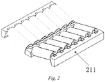
- Fig. 2 is a schematic structural diagram of a set of V-shaped rollers of the invention
- Fig. 3 is a schematic structural diagram of a set of I-shaped rollers of the invention
- Fig. 4 is a schematic structural diagram of a centring push/pull rod of the invention.
- the parking platform 21 is provided with a first positioning mechanism (not shown) capable of positioning the electric vehicle in a forward/backward direction and a second positioning mechanism (not shown in the figures) to position the electric vehicle in a width direction.
- the first positioning mechanism comprises two sets of V-shaped rollers 211 and two sets of I-shaped rollers 212.
- the two sets of V-shaped rollers 211 allow front/rear wheels of the vehicle 4 to be embedded therein so as to complete the positioning of the electric vehicle in the forward/backward direction, and the sets of V-shaped rollers 211 also enable the front/rear wheels of the vehicle 4 to move along the width direction of the electric vehicle.
- the two sets of I-shaped rollers 212 accordingly allow the rear/front wheels of the electric vehicle to be supported thereon and move along the width direction of the electric vehicle.
- the second positioning mechanism comprises a front wheel centring push/pull rod 213 and a rear wheel centring push/pull rod 213.
- the front wheel centring push/pull rod 213 and the rear wheel centring push/pull rod 213 may be provided as the same structure, and the front wheel centring push/pull rod 213 and the rear wheel centring push/pull rod 213 allow to position the electric vehicle in the width direction by pushing/pulling the wheels of the electric vehicle.
- first positioning mechanism and the second positioning mechanism are not invariable, and those skilled in the art may also adopt other position adjustment devices to position the electric vehicle without departing from the principles of the invention, as long as the positioning devices are able to position the electric vehicle on the parking platform 21.
- the battery transportation unit 22 comprises a first driving mechanism (not shown) and a first transmission mechanism (not shown) arranged on one side of the parking platform 21 close to the battery charging and storage module 1.
- the first driving mechanism is able to drive the first transmission mechanism to move, and the first transmission mechanism is able to carry the battery 3 and transport the battery to the locking/unlocking unit when being driven by the first driving mechanism.
- the first driving mechanism may be a power apparatus such as a servo motor, an electric cylinder or an air cylinder, and the first transmission mechanism may be an apparatus or a component that may carry the battery 3 and be used in cooperation with the driving mechanism, such as a sliding table, a conveyor belt, a roller wheel set or a roller set.
- a roller wheel set is used as the first transmission mechanism
- a servo motor is used as the first driving mechanism
- the whole battery transportation unit 22 is fixed on the parking platform 21 or on the ground of the battery charging and swap station, so as to achieve the transportation of the battery 3 between the locking/unlocking unit and the battery charging and storage module 1.
- the locking/unlocking unit may comprise a hoisting mechanism (not shown) and a plurality of locking/unlocking mechanisms (not shown).
- the hoisting mechanism may lower the used battery to the roller wheel set or raise the fresh battery to the battery swap position, and the locking/unlocking mechanism may lock/unlock the battery 3 at the battery swap position.
- the locking/unlocking mechanism is a drive motor and a locking/unlocking head (such as an inner hexagonal lock) arranged on an output shaft of the drive motor, and a plurality of locking/unlocking mechanisms may be fixed on a base plate to ensure the relative positions thereof.
- the hoisting mechanism may use a driving mechanism such as the air cylinder and the servo motor in cooperation with a guiding mechanism such as a guide rail, a sliding table, a cam mechanism and a rigid chain, to realize hoisting of the base plate and the battery 3 and the locking/unlocking mechanism on the base plate.
- the whole base plate may also be embedded in the parking platform 21 or fall on the ground of the battery charging and swap station to increase a space for battery swapping, and some hole structures are provided in positions on the base plate corresponding to the roller wheels, such that the battery 3 may smoothly fall on the roller wheel set after the base plate is lowered.
- the battery swap position may be a position where the locking/unlocking mechanism can lock/unlock the battery 3, for example a position where the locking/unlocking mechanism removes the used battery or installs the fresh battery simply by being driven by the driven motor after the locking/unlocking mechanism is aligned with the chassis of the electric vehicle via the hoisting mechanism.
- the locking/unlocking mechanism it is also possible to provide some positioning pins on the base plate, and the chassis of the electric vehicle is correspondingly provided with positioning holes. By plugging the positioning pins into the positioning holes, the positioning precision of the locking/unlocking mechanism is ensured.
- the invention by means of innovatively providing the battery transportation unit 22 and the locking/unlocking unit in the battery charging and swap station, allows for battery swapping without lifting the electric vehicle and with the battery swap robot and the lifting device eliminated, such that the steps for battery swapping are reduced and the battery swap efficiency and battery swap experience of a user. It can also be seen from the above description that the battery transportation unit 22 and the locking/unlocking unit have simple structures and are easy to implement, the invention also improves the reliability and stability of the battery charging and swap station, reduces construction cost and facilitates large-scale promotion and application.
- the vehicle lifting unit is configured to lift the electric vehicle parked on the parking platform 21 by a preset distance (for example the preset distance is 10 cm or 20 cm), such that enough operation space is available for the entry and exit of the battery 3 and the bottom locking/unlocking mechanism by raising the electric vehicle to effectively avoid interference caused by the vehicle body such as tires.
- the leveling unit is configured to adjust the degree of parallelism of the vehicle 4 and the parking platform 21 so as to keep the locking/unlocking mechanism parallel to the bottom of the vehicle and improving the battery swap accuracy of the locking/unlocking mechanism.
- both the vehicle lifting unit and the leveling unit may be implemented by adopting a motor, an electric cylinder, an air cylinder etc. as a driving power and adopting a vertical slide rail, a cam mechanism, a rigid chain, a screw rod, a gear as a transmission device.
- a servo motor is adopted as the driving power
- a screw slide rail is adopted as a transmission member and is connected to the set of I-shaped rollers 212, and the screw slide rail is driven by the motor to drive the set of I-shaped rollers 212 to move up and down to complete the lifting or leveling of the chassis of the electric vehicle.
- the vehicle lifting unit here may be configured the same as a lifting mechanism for lifting the vehicle 4 in the prior art, except that the vehicle lifting unit enables an increase in the operation space without need to lift the electric vehicle to be very high.
- the lifting mechanism in the prior art needs to lift the electric vehicle by 80 cm to leave enough space for the entry/exit of the battery swap robot, while the vehicle lifting unit in the invention only needs to lift the vehicle 4 by 20 cm, and even 10 cm, to achieve the same objective.
- lifting by 20 cm or 10 cm greatly reduces the danger to a driver sitting in the vehicle when the battery is swapped, such that the drive may stay in the vehicle while the battery is swapped.
- the locking/unlocking unit may also be configured with a translation unit 23.
- the translation unit 23 is configured to enable the locking/unlocking mechanism to move in the forward/backward direction of the vehicle 4. Similar to the foregoing, there may be various methods for driving the translation unit 23, and the motor, the air cylinder, and the electric cylinder etc. may still act as the driving power, and common screw slide rails, racks or the like are used as transmission members to connect to the chassis of the locking/unlocking unit.
- the battery 3 is not arranged at a centre position of the chassis of the electric vehicle, and the battery swap platform module 2 and the battery charging and storage module 1 in the battery charging and swap station are both centred as much as possible for the ease of design and control, which causes noncoincidence of the centres of the battery 3 and the locking/unlocking mechanism (specifically, the midpoint of the battery 3 along the forward/backward direction of the vehicle 4 does not coincide with that of the locking/unlocking mechanism) and mis alignment between the locking/unlocking mechanism and the battery swap position.
- the floor area of the battery swap platform and the battery charging and swap station needs to be increased. If the floor area on a side of the battery swap platform is increased, the midpoint of the vehicle 4 in the forward/backward direction is moved up or down so as to coincide with the midpoint of the battery 3 in that direction.
- the translation unit 23 by means of translation, aligns the midpoint of the locking/unlocking mechanism to that of the battery 3, which both fulfills the ease of design and reduces the overall size of the battery swap platform, such that the floor area of the battery charging and swap station is reduced and the miniaturization of the battery charging and swap station is realized.
- Fig. 5 is a schematic structural diagram of a battery transfer device of the invention.
- the battery storage device 11 further comprises a plurality of battery rack units 111.
- Each of the battery rack unit 111 is provided with a first battery transfer unit (not shown), and the first battery transfer unit comprises a second driving mechanism (not shown) and a second transmission mechanism (not shown).
- the second driving mechanism is able to drive the second transmission mechanism to move, and the second transmission mechanism is able to carry the battery 3, which realizes the function of the battery 3 entering/exiting the battery rack unit 111 for exchanging the battery 3 with the battery transfer device 12.
- each of the battery rack units 111 may be implemented in a modular arrangement, and the capacity of the battery storage unit may be increased by the addition of layers and rows, so as to meet more frequent battery swap requirements and more storage requirements.
- the second driving mechanism may still adopts the motor, the electric cylinder, and the air cylinder etc., and the second transmission mechanism adopts a screw nut, a guide rail, a chain, a roller wheel set, and a roller set, etc., in order to achieve the functions of the battery entering/exiting the battery storage device 11 and exchanging the battery with the battery transfer device 12.
- the battery rack units 111 may also be implemented by splicing an integral frame to improve the overall stability of the battery storage device 11.
- the battery transfer device 12 comprises a battery lifting unit 121 and at least one second battery transfer unit 122.
- the battery lifting unit 121 is configured to raise/lower the at least one battery transfer unit
- the second battery transfer unit 122 is configured to swap the battery 3 with the battery storage device 11 and battery transportation unit 22.
- the battery lifting unit 121 comprises a third driving mechanism 1211 and a third transmission mechanism 1212.
- the third driving mechanism 1211 is able to drive the third transmission mechanism 1212 to ascend/descend, and the third transmission mechanism 1212 is directly or indirectly connected to the at least one second battery transfer unit 122.
- the second battery transfer unit 122 comprises a fourth driving mechanism (not shown) and a fourth transmission mechanism (not shown).
- the fourth driving mechanism is able to drive the fourth transmission mechanism to move, and the fourth transmission mechanism is able to carry the battery 3, which realizes the function of the battery 3 entering/exiting the battery transfer device 12 for exchanging the battery 3 with the battery transfer device 12.
- the battery lifting unit 121 and the battery transfer unit 122 here may still adopt the motor, the electric cylinder, the air cylinder etc. as the third driving mechanism 1211 or the fourth driving mechanism, and adopts the screw nut, the guide rail, the chain, etc. as the third transmission mechanism 1212 or the fourth transmission mechanism, so as to lift and lower the battery and exchange the battery 3 with the battery transportation unit 22 and the battery storage device 11.
- a traverse rail 13 is further provided on the ground of the battery charging and swap station.
- the battery transfer device 12 may move under the guiding of the guide rail so as to dock with each of the battery rack units 111 in the battery transportation unit 22 and the battery storage device 11.
- the battery transfer device 12 may be provided with two second battery transfer units 122 arranged one above another or in left and right rows side by side, and the two battery transfer units are configured such that while or after one of the battery transfer units receives/transfers the used battery, the other one of the battery transfer units is able to transfer/receive the fresh battery.
- the battery transfer units are arranged one above another or in left and right rows side by side such that the battery transfer unit 12 may store two batteries simultaneously. In this way, during the battery swapping, the battery transfer device 12 may complete reception of the used battery and transfer of the fresh battery in a single operation, thus further speeding up the cycle of battery swapping.
- the battery transfer device 12 may be configured to move parallelly relative to the battery storage device 11 by means of the traverse rail 13 such that when the battery storage device 11 or the battery swap platform module 2 needs to be serviced, enough service space is left by translation of the battery transfer device 12, thus reducing the service difficulty.
- the driver drives the electric vehicle into the parking platform 21 and the electric vehicle is positioned with the limiting by the first positioning mechanism and the second positioning mechanism ⁇ the translation unit 23 causes the locking/unlocking unit to translate to a projection position of the battery swap position ⁇ the hoisting mechanism hoists the locking/unlocking mechanism to the battery swap position ⁇ the locking/unlocking mechanism removes the used battery, and the used battery falls on the base plate of the locking/unlocking unit ⁇ the translation unit 23 causes the locking/unlocking unit to translate to an original position, the hoisting mechanism lowers the locking/unlocking unit, and the used battery falls on the roller wheel set of the battery transportation unit 22 ⁇ the battery transportation unit 22 delivers the used battery to the battery transfer device 12, and the upper second battery transfer unit 122 of the battery transfer device 12 receives the used battery ⁇ after the second battery transfer unit 122 receives the used battery, the battery lifting unit 121 raises the two second battery transfer units 122 simultaneously, and then the lower second battery transfer unit 122 docks with the battery transportation unit 22
- the above description of the battery swap process is only to illustrate the working principles of the invention and is not intended to limit the scope of protection of the invention. and adjustments may be made by those skilled in the art to the sequence of actions of the above process or mechanism without departing from the principles of the invention, such that the invention can apply to more specific application scenarios.
- the action of the translation unit 23 causing the locking/unlocking unit to translate to the original position and the action of the hoisting mechanism lowering the locking/unlocking mechanism may also be performed simultaneously.
- the lower second battery transfer unit 122 of the battery transfer device 12 when the battery transportation unit 22 exchanges the battery with the battery transfer device 12, it is also possible for the lower second battery transfer unit 122 of the battery transfer device 12 to first receive the used battery before the upper second battery transfer unit 122 transfers the fresh battery to the battery transportation unit 22.
Abstract
Description
- The invention relates to the field of battery swapping, and in particular to a battery charging and swap station.
- With the popularization of new energy vehicles, how to effectively provide rapid and effective energy replenishment for vehicles with insufficient energy has become a very concerned problem for vehicle owners and major manufacturers. Taking electric vehicles as an example, the current mainstream electric energy replenishment solutions include a charging solution and a battery swapping solution. Compared with the charging solution, the battery swapping solution can swap a traction battery in a very short time and does not significantly affect the service life of the traction battery, and is therefore one of the main development directions of electric energy replenishment. The battery swapping solution is generally completed in a battery charging and swap station. The battery charging and swap station is internally provided with a battery rack for storing batteries and a battery swap platform as well as a battery swap robot, such as a Rail Guided Vehicle (RGV) or an Auto Guided Vehicle (AGV), for carrying a fresh/used traction battery between the battery rack and the battery swap platform. The battery swap robot implements the transportation of the battery and the swapping of a battery of the electric vehicle by means of reciprocating between the battery rack and the battery swap platform.
- Although the battery swapping solution has many advantages mentioned above, certain problems inevitably exist. First, since the battery swap robot has the two functions of battery transportation and swapping integrated therein, the height of the battery swap robot is relatively high such that the battery swap platform needs to be provided with a dedicated lifting device to raise the electric vehicle to a higher height before the battery swap robot enter the bottom of the vehicle for battery swapping. Moreover, this configuration also requires that during the battery swapping, the driver (a passenger or a battery swap service personnel) needs to park the vehicle, gets off the vehicle and waits until the end of the battery swap process, and then gets on the vehicle and drives same away. This process is proper for safety reasons, but results in a very poor user experience. Second, for both the rail guided vehicle and the auto guided vehicle, a dedicated rail or guide line needs to be laid in the battery charging and swap station, and the rail or the guide line needs to occupy two regions, i.e. the battery rack and the battery swap platform, which fails to implement modular installation and transportation of the battery charging and swap station and causes inconveniences in transportation and installation to the manufacturer of the battery charging and swap station.
- Accordingly, there is a need in the art for a novel battery charging and swap station to solve the above problems.
- To solve the above-mentioned problems in the prior art, that is, to solve the problems of poor battery swap experience and inconvenient transportation and installation present in existing battery charging and swap stations, the invention provides a battery charging and swap station. The battery charging and swap station comprises a battery charging and storage module and a battery swap platform module, wherein the battery charging and storage module stores a plurality of batteries, and the battery charging and storage module is configured to dock with and exchange a battery with the battery swap platform module; and wherein the battery swap platform module is configured to transport the battery and to swap a battery of a vehicle.
- In a preferred technical solution of the above-mentioned battery charging and swap station, the battery swap platform module comprises: a parking platform configured to position a vehicle parked thereon; a locking/unlocking unit configured to remove a used battery from the vehicle and install a fresh battery to the vehicle; and a battery transportation unit configured to transport the used battery removed by the locking/unlocking unit to the battery charging and storage module and to receive the fresh battery from the battery charging and storage module and transport the fresh battery to the locking/unlocking unit.
- In a preferred technical solution of the above-mentioned battery charging and swap station, the battery transportation unit is further configured to transport the used battery removed by the locking/unlocking unit to the battery charging and storage module without lifting the vehicle, and to receive the fresh battery from the battery charging and storage module and transport the fresh battery to the locking/unlocking unit.
- In a preferred technical solution of the above-mentioned battery charging and swap station, the battery transportation unit comprises a first driving mechanism and a first transmission mechanism, wherein the first driving mechanism is able to drive the first transmission mechanism to move, and the first transmission mechanism is able to carry the battery.
- In a preferred technical solution of the above-mentioned battery charging and swap station, the locking/unlocking unit comprises a hoisting mechanism and a locking/unlocking mechanism, wherein the hoisting mechanism is able to hoist the locking/unlocking mechanism to a battery swap position, and the locking/unlocking mechanism is able to lock/unlock the battery at the battery swap position.
- In a preferred technical solution of the above-mentioned battery charging and swap station, the locking/unlocking unit is further configured with a translation unit, wherein the translation unit enables the locking/unlocking unit to move in forward/backward direction of the vehicle.
- In a preferred technical solution of the above-mentioned battery charging and swap station, the parking platform is provided with a first positioning mechanism and a second positioning mechanism, wherein the first positioning mechanism enables the vehicle to be positioned in a forward/backward direction of the vehicle, and the second positioning mechanism enables the vehicle to be positioned in a width direction of the vehicle.
- In a preferred technical solution of the above-mentioned battery charging and swap station, the first positioning mechanism comprises a set of V-shaped rollers and a set of I-shaped rollers, wherein the set of V-shaped rollers enables front/rear wheels of the vehicle to be embedded therein, and the set of V-shaped rollers allows the front/rear wheels of the vehicle to move in the width direction; and the set of I-shaped rollers respectively allows the rear/front wheels of the vehicle to be supported thereon and to move in the width direction.
- In a preferred technical solution of the above-mentioned battery charging and swap station, the second positioning mechanism comprises a front wheel centring push/pull rod and/or a rear wheel centring push/pull rod, wherein the front wheel centring push/pull rod and/or the rear wheel centring push/pull rod enable the vehicle to be positioned in the width direction by means of pushing/pulling the front/rear wheels of the vehicle.
- In a preferred technical solution of the above-mentioned battery charging and swap station, the battery swap platform module further comprises a vehicle lifting unit and/or a leveling unit, wherein the vehicle lifting unit is able to raise the vehicle parked on the parking platform by a preset distance; and wherein the leveling unit is able to adjust the degree of parallelism of the vehicle and the parking platform.
- In a preferred technical solution of the above-mentioned battery charging and swap station, the battery charging and storage module comprises a battery storage device and a battery transfer device, wherein the battery storage device stores a plurality of batteries, and the battery storage device is configured to dock with and exchange the battery with the battery transfer device; and the battery transfer device is configured to receive the used battery from the battery transportation unit and transfer the used battery to the battery storage device, and to receive the fresh battery from the battery storage device and transfer the fresh battery to the battery transportation unit.
- In a preferred technical solution of the above-mentioned battery charging and swap station, the battery storage device further comprise a plurality of battery rack units, wherein each of the battery rack units is provided with a first battery transfer unit, and the first battery transfer unit is configured to enable the battery to enter/exit the battery rack unit.
- In a preferred technical solution of the above-mentioned battery charging and swap station, the first battery transfer unit comprises a second driving mechanism and a second transmission mechanism, wherein the second driving mechanism is able to drive the second transmission mechanism to move, and the second transmission mechanism is able to carry the battery.
- In a preferred technical solution of the above-mentioned battery charging and swap station, the battery transfer device comprises a battery lifting unit and at least one second battery transfer unit, wherein the battery lifting unit is configured to enable the at least one second battery transfer unit to ascend/descend, and the second battery transfer unit is configured to enable the battery to enter/exit the battery transfer device.
- In a preferred technical solution of the above-mentioned battery charging and swap station, the battery transfer device comprises two second battery transfer units, wherein the two second battery transfer units are configured in such a way that: while or after one of the second battery transfer units receives/transfers the used battery, the other one of the second battery transfer units is able to respectively transfer/receive the fresh battery.
- In a preferred technical solution of the above-mentioned battery charging and swap station, the battery lifting unit comprises a third driving mechanism and a third transmission mechanism, wherein the third driving mechanism is able to drive the third transmission mechanism to ascend/descend, and the third transmission mechanism is connected to the at least one second battery transfer unit.
- In a preferred technical solution of the above-mentioned battery charging and swap station, the second battery transfer unit comprises a fourth driving mechanism and a fourth transmission mechanism, wherein the fourth driving mechanism is able to drive the fourth transmission mechanism to move, and the fourth transmission mechanism is able to carry the battery.
- Those skilled in the art can understand that, in a preferred technical solution of the invention, the battery charging and swap station comprises the battery charging and storage module and the battery swap platform module, and comprises no battery swap robot. The battery charging and storage module is configured to dock with and exchange the battery with the battery swap platform module, and the battery swap platform module is configured to transport the battery and to swap the battery of a vehicle. The battery swap platform module further comprises a parking platform, a locking/unlocking unit and a battery transportation unit, wherein the battery transportation unit is further configured to transport the used battery removed by the locking/unlocking unit to the battery charging and storage module without lifting the vehicle, and to receive the fresh battery from the battery charging and storage module and transport the fresh battery to the locking/unlocking unit. By achieving the functions of the battery swap robot of transporting and replacing the battery using the battery swap platform module, the battery charging and swap station of the invention allows to complete the battery swapping without providing the battery swap robot and a vehicle lifting mechanism. This configuration eliminates the vehicle lifting process during the battery swapping, speeds up the cycle of battery swapping, and allows to complete the battery swapping without the driver getting off from the vehicle. Meanwhile, the structure of the battery charging and swap station may be greatly simplified, that is, the arrangement of the battery swap robot,the rail, and the vehicle lifting mechanism is simplified, such that modular transportation and installation of the overall station is allowed with the battery swap platform module and the battery charging and storage module as two separate modules. That is to say, the battery charging and swap station of the invention solves the problems of poor battery swap experience and inconvenient transportation and installation of the existing battery charging and swap stations, realizes miniaturization and monolithic assembly and transportation of the battery charging and swap station, reduces civil work for the battery charging and swap station, facilitates the installation and setup of the charging and replacing power station in a city, and improves battery swap efficiency and the battery swap experience.
- The battery charging and swap station of the invention will be described below with reference to accompanying drawings and in conjunction with electric vehicles. In the accompanying drawings:
-
Fig. 1 is a schematic structural diagram of a battery charging and swap station of the invention; -
Fig. 2 is a schematic structural diagram of a set of V-shaped rollers of the invention; -
Fig. 3 is a schematic structural diagram of a set of I-shaped rollers of the invention; -
Fig. 4 is a schematic structural diagram of a centring push/pull rod of the invention; -
Fig. 5 is a schematic structural diagram of a battery transfer device of the invention; -
Fig. 6 is a schematic structural diagram (I) of the battery charging and swap station of the invention with a translation unit; and -
Fig. 7 is a schematic structural diagram (II) of the battery charging and swap station of the invention with the translation unit; - 1. Battery charging and storage module; 11. Battery storage device; 111. Battery rack unit; ; 12. Battery transfer device; 121. Battery lifting unit; 1211. Third driving mechanism; 1212. Third transmission mechanism; 122. Second battery transfer unit; 13. Traverse rail; 2. Battery swap platform module; 21. Parking platform; 211. Set of V-shaped rollers; 212. Set of I-shaped rollers; 213. Centring push/pull rod; 22. Battery transportation unit; 23. Translation unit; 3. Battery; 4. Vehicle.
- Preferred embodiments of the invention are described below with reference to the accompanying drawings. It should be understood by those skilled in the art that these embodiments are only for explaining the technical principles of the invention and are not intended to limit the scope of protection of the invention. For example, although the third transmission mechanism in the figures is described as chain transmission, this configuration is not invariable, and those skilled in the art may make adjustments as desired to adapt to specific applications.
- It should be noted that in the description of the invention, the terms, such as "center", "upper", "lower", "left", "right", "vertical", "horizontal", "inner" and "outer", that indicate directions or positional relationships are based on the directions or positional relationships shown in the drawings only for convenience of description, and do not indicate or imply that the device or element must have a specific orientation, be constructed and operated in a specific orientation, and therefore cannot be understood as limitation to the invention. In addition, the terms "first", "second" and "third" are for descriptive purposes only and should not be construed as indicating or implying relative importance.
- In addition, it should also be noted that, in the description of the invention, the terms "install", "couple" and "connect" should be interpreted in a broad sense unless explicitly stated and limited otherwise, and, for example, can mean a fixed connection, a detachable connection or an integral connection; can mean a mechanical connection or an electrical connection; and can mean a direct connection, an indirect connection by means of an intermediary, or internal communication between two elements. For a person skilled in the art, the specific meaning of the above terms in the invention can be interpreted according to a specific situation.
- In order to solve the problems of poor battery swap experience and inconvenient transportation and installation in the existing battery charging and swap stations, by the configuration in which the battery swap robot in the battery charging and swap station is eliminated and the battery swap robot is substituted with the battery transportation unit and the locking/unlocking unit in the battery swap platform module to realize the functions of transportation and replacement of a traction battery (hereinafter referred to as battery), the invention allows miniaturization and monolithic assembly and transportation of the battery charging and swap station, speeds up the cycle of battery swapping, and improves the battery swap experience.
- Referring to
Fig. 1 first,Fig. 1 is a schematic structural diagram of a battery charging and swap station of the invention. - As shown in
Fig. 1 , the battery charging and swap station of the invention mainly comprises a battery charging andstorage module 1 and a batteryswap platform module 2, and comprises no battery swap robot. The battery charging andstorage module 1 stores a plurality ofbatteries 3, and the battery charging andstorage module 1 is configured to dock with and exchange thebattery 3 with the batteryswap platform module 2. The batteryswap platform module 2 is configured to transport thebattery 3 and swap thebattery 3 for an electric vehicle. The batteryswap platform module 2 further comprises aparking platform 21, a locking/unlocking unit (not shown) and abattery transportation unit 22. Theparking platform 21 is configured to position the electric vehicle parked thereon, and the locking/unlocking unit is configured to remove a used battery from the electric vehicle and install a fresh battery to the electric vehicle. Thebattery transportation unit 22 is preferably configured to directly transport the used battery removed by the locking/unlocking unit to the battery charging andstorage module 1 without lifting the electric vehicle, and to receive the fresh battery from the battery charging andstorage module 1 and transport the fresh battery to the locking/unlocking unit. The battery charging andstorage module 1 comprises abattery storage device 11 and abattery transfer device 12. Thebattery storage device 11 stores the plurality ofbatteries 3, and thebattery storage device 11 is configured to be able to charge, discharge, and cool thebatteries 3 stored thereon, and to dock with and exchange thebattery 3 with thebattery transfer device 12. Thebattery transfer device 12 is configured to receive the used battery from thebattery transportation unit 22 and transfer the used battery to thebattery storage device 11, and to receive the fresh battery from thebattery storage device 11 and transfer the fresh battery to thebattery transportation unit 22. - For example, the battery charging and
storage module 1 and the batteryswap platform module 2 each may be arranged in one shipping container with one open side, and the open sides of two shipping containers are assembled by means of splicing to form the battery charging and swap station of the invention. When thebattery 3 is replaced for the electric vehicle parked on theparking platform 21, it is unnecessary to lift thevehicle 4, and the locking/unlocking unit first removes the used battery from the electric vehicle, and the removed used battery falls onto thebattery transportation unit 22; then thebattery transportation unit 22 transports the used battery out of the bottom of the vehicle and reaches thebattery transfer device 12, and thebattery transfer device 12 receives the used battery and then transfers the fresh battery to thebattery transportation unit 22 so as to completes exchange of thebattery 3 with thebattery transportation unit 22; finally, thebattery transportation unit 22 transports the fresh battery to the bottom of the electric vehicle, the fresh battery is installed on the electric vehicle by the locking/unlocking unit, and battery swapping is completed for the electric vehicle. - As can be seen from the above description, the invention, by means of dividing the battery charging and swap station into two modules that are functionally independent of each other, i.e. the battery charging and
storage module 1 and the batteryswap platform module 2, enables the battery charging and swap station to have the advantages of monolithic assembly and transportation, no civil work, and easy installation. The configuration in which thebattery transportation unit 22 and the locking/unlocking unit are used instead of the existing battery swap robot may thus eliminate the provision of the battery swap robot and a lifting device and achieve the objective of replacing thebattery 3 without lifting the electric vehicle, such that the battery charging and swap station has a simpler overall structure and an improved structure stability. In other words, the above-mentioned configuration reduces the construction cost of the battery swap station, improves the battery swapping stability and battery swap efficiency, and solves many problems present in the existing battery charging and swap station, such as complicated system structure, redundant process of battery swapping, and cumbersome steps for installing and transporting, and low battery swap efficiency. - It should be noted that, the above-mentioned configuration is only intended to explain the principles of the invention, and is not intended to limit the scope of protection of the invention. and adjustments may be made by those skilled in the art to the above-mentioned configuration to adapt to more specific application scenarios without departing from the principles of the invention. For example, the battery charging and
storage module 1 and the batteryswap platform module 2 may also be built using a frame structure, and thebattery storage device 11 may also be used to only store thebatteries 3 and has no functions of charging, discharging and cooling. - The principles of the invention will be further described below with reference to
Figs. 1 to 4 .Fig. 2 is a schematic structural diagram of a set of V-shaped rollers of the invention;Fig. 3 is a schematic structural diagram of a set of I-shaped rollers of the invention; andFig. 4 is a schematic structural diagram of a centring push/pull rod of the invention. - As shown in
Figs. 1 to 4 , in a possible embodiment, theparking platform 21 is provided with a first positioning mechanism (not shown) capable of positioning the electric vehicle in a forward/backward direction and a second positioning mechanism (not shown in the figures) to position the electric vehicle in a width direction. The first positioning mechanism comprises two sets of V-shapedrollers 211 and two sets of I-shapedrollers 212. The two sets of V-shapedrollers 211 allow front/rear wheels of thevehicle 4 to be embedded therein so as to complete the positioning of the electric vehicle in the forward/backward direction, and the sets of V-shapedrollers 211 also enable the front/rear wheels of thevehicle 4 to move along the width direction of the electric vehicle. The two sets of I-shapedrollers 212 accordingly allow the rear/front wheels of the electric vehicle to be supported thereon and move along the width direction of the electric vehicle. The second positioning mechanism comprises a front wheel centring push/pull rod 213 and a rear wheel centring push/pull rod 213. The front wheel centring push/pull rod 213 and the rear wheel centring push/pull rod 213 may be provided as the same structure, and the front wheel centring push/pull rod 213 and the rear wheel centring push/pull rod 213 allow to position the electric vehicle in the width direction by pushing/pulling the wheels of the electric vehicle. Of course, the form and number of the first positioning mechanism and the second positioning mechanism are not invariable, and those skilled in the art may also adopt other position adjustment devices to position the electric vehicle without departing from the principles of the invention, as long as the positioning devices are able to position the electric vehicle on theparking platform 21. - Return to
Fig. 1 , in a possible embodiment, thebattery transportation unit 22 comprises a first driving mechanism (not shown) and a first transmission mechanism (not shown) arranged on one side of theparking platform 21 close to the battery charging andstorage module 1. The first driving mechanism is able to drive the first transmission mechanism to move, and the first transmission mechanism is able to carry thebattery 3 and transport the battery to the locking/unlocking unit when being driven by the first driving mechanism. The first driving mechanism may be a power apparatus such as a servo motor, an electric cylinder or an air cylinder, and the first transmission mechanism may be an apparatus or a component that may carry thebattery 3 and be used in cooperation with the driving mechanism, such as a sliding table, a conveyor belt, a roller wheel set or a roller set. For example, a roller wheel set is used as the first transmission mechanism, a servo motor is used as the first driving mechanism, and the wholebattery transportation unit 22 is fixed on theparking platform 21 or on the ground of the battery charging and swap station, so as to achieve the transportation of thebattery 3 between the locking/unlocking unit and the battery charging andstorage module 1. - In a possible implementation, the locking/unlocking unit may comprise a hoisting mechanism (not shown) and a plurality of locking/unlocking mechanisms (not shown). The hoisting mechanism may lower the used battery to the roller wheel set or raise the fresh battery to the battery swap position, and the locking/unlocking mechanism may lock/unlock the
battery 3 at the battery swap position. For example, the locking/unlocking mechanism is a drive motor and a locking/unlocking head (such as an inner hexagonal lock) arranged on an output shaft of the drive motor, and a plurality of locking/unlocking mechanisms may be fixed on a base plate to ensure the relative positions thereof. The hoisting mechanism may use a driving mechanism such as the air cylinder and the servo motor in cooperation with a guiding mechanism such as a guide rail, a sliding table, a cam mechanism and a rigid chain, to realize hoisting of the base plate and thebattery 3 and the locking/unlocking mechanism on the base plate. The whole base plate may also be embedded in theparking platform 21 or fall on the ground of the battery charging and swap station to increase a space for battery swapping, and some hole structures are provided in positions on the base plate corresponding to the roller wheels, such that thebattery 3 may smoothly fall on the roller wheel set after the base plate is lowered. The battery swap position may be a position where the locking/unlocking mechanism can lock/unlock thebattery 3, for example a position where the locking/unlocking mechanism removes the used battery or installs the fresh battery simply by being driven by the driven motor after the locking/unlocking mechanism is aligned with the chassis of the electric vehicle via the hoisting mechanism. - Further, in order to improve the positioning precision of the locking/unlocking mechanism, it is also possible to provide some positioning pins on the base plate, and the chassis of the electric vehicle is correspondingly provided with positioning holes. By plugging the positioning pins into the positioning holes, the positioning precision of the locking/unlocking mechanism is ensured.
- As described above, compared with the configuration in which the transportation and replacement of the
battery 3 are carried out by the battery swap robot in the prior art, the invention, by means of innovatively providing thebattery transportation unit 22 and the locking/unlocking unit in the battery charging and swap station, allows for battery swapping without lifting the electric vehicle and with the battery swap robot and the lifting device eliminated, such that the steps for battery swapping are reduced and the battery swap efficiency and battery swap experience of a user. It can also be seen from the above description that thebattery transportation unit 22 and the locking/unlocking unit have simple structures and are easy to implement, the invention also improves the reliability and stability of the battery charging and swap station, reduces construction cost and facilitates large-scale promotion and application. - Of course, the above embodiments are not unique, and any adjustment made in forms should fall within the scope of protection of the invention without departing from the principles of the invention.
- For example, in a possible embodiment, in order to increase the space for battery swapping and improve the battery swap accuracy, it is also possible to provide a vehicle lifting unit (not shown) and/or a leveling unit (not shown) on the
parking platform 21. The vehicle lifting unit is configured to lift the electric vehicle parked on theparking platform 21 by a preset distance (for example the preset distance is 10 cm or 20 cm), such that enough operation space is available for the entry and exit of thebattery 3 and the bottom locking/unlocking mechanism by raising the electric vehicle to effectively avoid interference caused by the vehicle body such as tires. The leveling unit is configured to adjust the degree of parallelism of thevehicle 4 and theparking platform 21 so as to keep the locking/unlocking mechanism parallel to the bottom of the vehicle and improving the battery swap accuracy of the locking/unlocking mechanism. In the implementation, both the vehicle lifting unit and the leveling unit may be implemented by adopting a motor, an electric cylinder, an air cylinder etc. as a driving power and adopting a vertical slide rail, a cam mechanism, a rigid chain, a screw rod, a gear as a transmission device. For example: a servo motor is adopted as the driving power, and a screw slide rail is adopted as a transmission member and is connected to the set of I-shapedrollers 212, and the screw slide rail is driven by the motor to drive the set of I-shapedrollers 212 to move up and down to complete the lifting or leveling of the chassis of the electric vehicle. - It should be noted that the vehicle lifting unit here may be configured the same as a lifting mechanism for lifting the
vehicle 4 in the prior art, except that the vehicle lifting unit enables an increase in the operation space without need to lift the electric vehicle to be very high. For example, the lifting mechanism in the prior art needs to lift the electric vehicle by 80 cm to leave enough space for the entry/exit of the battery swap robot, while the vehicle lifting unit in the invention only needs to lift thevehicle 4 by 20 cm, and even 10 cm, to achieve the same objective. Compared with lifting by 80 cm, lifting by 20 cm or 10 cm greatly reduces the danger to a driver sitting in the vehicle when the battery is swapped, such that the drive may stay in the vehicle while the battery is swapped. - Now referring to
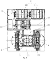
Figs. 6 and7 ,Fig. 6 is a schematic structural diagram (I) of a battery charging and swap station of the invention with a translation unit; andFig. 7 is a schematic structural diagram (II) of the battery charging and swap station of the invention with the translation unit. - In another possible embodiment, in order to further reduce the overall size of the battery swap platform and realize miniaturization of the battery charging and swap station, the locking/unlocking unit may also be configured with a
translation unit 23. Thetranslation unit 23 is configured to enable the locking/unlocking mechanism to move in the forward/backward direction of thevehicle 4. Similar to the foregoing, there may be various methods for driving thetranslation unit 23, and the motor, the air cylinder, and the electric cylinder etc. may still act as the driving power, and common screw slide rails, racks or the like are used as transmission members to connect to the chassis of the locking/unlocking unit. The reason for this arrangement is that thebattery 3 is not arranged at a centre position of the chassis of the electric vehicle, and the batteryswap platform module 2 and the battery charging andstorage module 1 in the battery charging and swap station are both centred as much as possible for the ease of design and control, which causes noncoincidence of the centres of thebattery 3 and the locking/unlocking mechanism (specifically, the midpoint of thebattery 3 along the forward/backward direction of thevehicle 4 does not coincide with that of the locking/unlocking mechanism) and mis alignment between the locking/unlocking mechanism and the battery swap position. At this point, if the midpoint of thebattery 3 along the forward/backward direction of thevehicle 4 is to coincide with that of the locking/unlocking mechanism, the floor area of the battery swap platform and the battery charging and swap station needs to be increased. If the floor area on a side of the battery swap platform is increased, the midpoint of thevehicle 4 in the forward/backward direction is moved up or down so as to coincide with the midpoint of thebattery 3 in that direction. The configuration in which thetranslation unit 23 is used to move the locking/unlocking mechanism in the forward/backward direction of thevehicle 4, thetranslation unit 23, by means of translation, aligns the midpoint of the locking/unlocking mechanism to that of thebattery 3, which both fulfills the ease of design and reduces the overall size of the battery swap platform, such that the floor area of the battery charging and swap station is reduced and the miniaturization of the battery charging and swap station is realized. - Now referring to
Figs. 1 and5, Fig. 5 is a schematic structural diagram of a battery transfer device of the invention. As shown inFig. 1 , thebattery storage device 11 further comprises a plurality ofbattery rack units 111. Each of thebattery rack unit 111 is provided with a first battery transfer unit (not shown), and the first battery transfer unit comprises a second driving mechanism (not shown) and a second transmission mechanism (not shown). The second driving mechanism is able to drive the second transmission mechanism to move, and the second transmission mechanism is able to carry thebattery 3, which realizes the function of thebattery 3 entering/exiting thebattery rack unit 111 for exchanging thebattery 3 with thebattery transfer device 12. In the implementation, each of thebattery rack units 111 may be implemented in a modular arrangement, and the capacity of the battery storage unit may be increased by the addition of layers and rows, so as to meet more frequent battery swap requirements and more storage requirements. The second driving mechanism may still adopts the motor, the electric cylinder, and the air cylinder etc., and the second transmission mechanism adopts a screw nut, a guide rail, a chain, a roller wheel set, and a roller set, etc., in order to achieve the functions of the battery entering/exiting thebattery storage device 11 and exchanging the battery with thebattery transfer device 12. Of course, thebattery rack units 111 may also be implemented by splicing an integral frame to improve the overall stability of thebattery storage device 11. - As shown in
Fig. 5 , in a possible embodiment, thebattery transfer device 12 comprises abattery lifting unit 121 and at least one secondbattery transfer unit 122. Thebattery lifting unit 121 is configured to raise/lower the at least one battery transfer unit, and the secondbattery transfer unit 122 is configured to swap thebattery 3 with thebattery storage device 11 andbattery transportation unit 22. Specifically, thebattery lifting unit 121 comprises athird driving mechanism 1211 and athird transmission mechanism 1212. Thethird driving mechanism 1211 is able to drive thethird transmission mechanism 1212 to ascend/descend, and thethird transmission mechanism 1212 is directly or indirectly connected to the at least one secondbattery transfer unit 122. The secondbattery transfer unit 122 comprises a fourth driving mechanism (not shown) and a fourth transmission mechanism (not shown). The fourth driving mechanism is able to drive the fourth transmission mechanism to move, and the fourth transmission mechanism is able to carry thebattery 3, which realizes the function of thebattery 3 entering/exiting thebattery transfer device 12 for exchanging thebattery 3 with thebattery transfer device 12. In order to ensure the unity of components and facilitate maintenance and replacement, thebattery lifting unit 121 and thebattery transfer unit 122 here may still adopt the motor, the electric cylinder, the air cylinder etc. as thethird driving mechanism 1211 or the fourth driving mechanism, and adopts the screw nut, the guide rail, the chain, etc. as thethird transmission mechanism 1212 or the fourth transmission mechanism, so as to lift and lower the battery and exchange thebattery 3 with thebattery transportation unit 22 and thebattery storage device 11. In addition, in order to couple thebattery transfer device 12 to thebattery storage device 11 and thebattery transportation unit 22 respectively, atraverse rail 13 is further provided on the ground of the battery charging and swap station. Thebattery transfer device 12 may move under the guiding of the guide rail so as to dock with each of thebattery rack units 111 in thebattery transportation unit 22 and thebattery storage device 11. - In a more preferred embodiment, the
battery transfer device 12 may be provided with two secondbattery transfer units 122 arranged one above another or in left and right rows side by side, and the two battery transfer units are configured such that while or after one of the battery transfer units receives/transfers the used battery, the other one of the battery transfer units is able to transfer/receive the fresh battery. The battery transfer units are arranged one above another or in left and right rows side by side such that thebattery transfer unit 12 may store two batteries simultaneously. In this way, during the battery swapping, thebattery transfer device 12 may complete reception of the used battery and transfer of the fresh battery in a single operation, thus further speeding up the cycle of battery swapping. Also, thebattery transfer device 12 may be configured to move parallelly relative to thebattery storage device 11 by means of thetraverse rail 13 such that when thebattery storage device 11 or the batteryswap platform module 2 needs to be serviced, enough service space is left by translation of thebattery transfer device 12, thus reducing the service difficulty. - A possible battery swap process of the battery charging and swap station of the invention will be described briefly with reference to
Figs. 6 and7 . - The driver drives the electric vehicle into the parking platform 21 and the electric vehicle is positioned with the limiting by the first positioning mechanism and the second positioning mechanism →the translation unit 23 causes the locking/unlocking unit to translate to a projection position of the battery swap position →the hoisting mechanism hoists the locking/unlocking mechanism to the battery swap position →the locking/unlocking mechanism removes the used battery, and the used battery falls on the base plate of the locking/unlocking unit →the translation unit 23 causes the locking/unlocking unit to translate to an original position, the hoisting mechanism lowers the locking/unlocking unit, and the used battery falls on the roller wheel set of the battery transportation unit 22 →the battery transportation unit 22 delivers the used battery to the battery transfer device 12, and the upper second battery transfer unit 122 of the battery transfer device 12 receives the used battery →after the second battery transfer unit 122 receives the used battery, the battery lifting unit 121 raises the two second battery transfer units 122 simultaneously, and then the lower second battery transfer unit 122 docks with the battery transportation unit 22 → the lower second battery transfer unit 122 transfers the stored fresh battery to the battery transportation unit 22 →the battery transportation unit 22 receives the fresh battery and transport the fresh battery to the base plate of the locking/unlocking unit →the translation unit 23 causes the locking/unlocking unit to translate to the projection position of the battery swap position again →the hoisting mechanism hoists the locking/unlocking mechanism to the battery swap position again →the locking/unlocking mechanism installs the fresh battery on the electric vehicle →the hoisting mechanism lowers the locking/unlocking mechanism, and the translation unit 23 causes the locking/unlocking unit to translate to the original position →the second positioning mechanism moves in an opposite direction and eliminates the limiting on the tires of the vehicle, and the driver drives the electric vehicle away from the battery charging and swap station.
- Of course, the above description of the battery swap process is only to illustrate the working principles of the invention and is not intended to limit the scope of protection of the invention. and adjustments may be made by those skilled in the art to the sequence of actions of the above process or mechanism without departing from the principles of the invention, such that the invention can apply to more specific application scenarios. As an example, after the locking/unlocking mechanism installs the fresh battery on the electric vehicle, the action of the
translation unit 23 causing the locking/unlocking unit to translate to the original position and the action of the hoisting mechanism lowering the locking/unlocking mechanism may also be performed simultaneously. As another example, when thebattery transportation unit 22 exchanges the battery with thebattery transfer device 12, it is also possible for the lower secondbattery transfer unit 122 of thebattery transfer device 12 to first receive the used battery before the upper secondbattery transfer unit 122 transfers the fresh battery to thebattery transportation unit 22. - Heretofore, the technical solutions of the invention have been described with reference to the preferred embodiments shown in the accompanying drawings; however, those skilled in the art can readily understand that the scope of protection of the invention is obviously not limited to these particular embodiments. Those skilled in the art can make equivalent changes or substitutions to the related technical features without departing from the principles of the invention, and all the technical solutions after the changes or substitutions will fall within the scope of protection of the invention.
Claims (17)
- A battery charging and swap station, characterized by comprising a battery charging and storage module and a battery swap platform module,
wherein the battery charging and storage module stores a plurality of batteries, and the battery charging and storage module is configured to dock with and exchange a battery with the battery swap platform module;
and wherein the battery swap platform module is configured to transport the battery and to swap a battery of a vehicle. - The battery charging and swap station according to claim 1, characterized in that the battery swap platform module comprises:a parking platform configured to position a vehicle parked thereon;a locking/unlocking unit configured to remove a used battery from the vehicle and install a fresh battery to the vehicle; anda battery transportation unit configured to transport the used battery removed by the locking/unlocking unit to the battery charging and storage module and to receive the fresh battery from the battery charging and storage module and transport the fresh battery to the locking/unlocking unit.
- The battery charging and swap station according to claim 2, characterized in that the battery transportation unit is further configured to transport the used battery removed by the locking/unlocking unit to the battery charging and storage module without lifting the vehicle, and to receive the fresh battery from the battery charging and storage module and transport the fresh battery to the locking/unlocking unit.
- The battery charging and swap station according to claim 3, characterized in that the battery transportation unit comprises a first driving mechanism and a first transmission mechanism, wherein the first driving mechanism is able to drive the first transmission mechanism to move, and the first transmission mechanism is able to carry the battery.
- The battery charging and swap station according to claim 2, characterized in that the locking/unlocking unit comprises a hoisting mechanism and a locking/unlocking mechanism, wherein the hoisting mechanism is able to hoist the locking/unlocking mechanism to a battery swap position, and the locking/unlocking mechanism is able to lock/unlock the battery at the battery swap position.
- The battery charging and swap station according to claim 5, characterized in that the locking/unlocking unit is further provided with a translation unit, wherein the translation unit enables the locking/unlocking unit to move in a forward/backward direction of the vehicle.
- The battery charging and swap station according to claim 2, characterized in that the parking platform is provided with a first positioning mechanism and a second positioning mechanism, wherein the first positioning mechanism enables the vehicle to be positioned in a forward/backward direction of the vehicle, and the second positioning mechanism enables the vehicle to be positioned in a width direction of the vehicle.
- The battery charging and swap station according to claim 7, characterized in that the first positioning mechanism comprises a set of V-shaped rollers and a set of I-shaped rollers, wherein the set of V-shaped rollers enables front/rear wheels of the vehicle to be embedded therein, and the set of V-shaped rollers allows the front/rear wheels of the vehicle to move in the width direction; and the set of I-shaped rollers respectively allows the rear/front wheels of the vehicle to be supported thereon and to move in the width direction.
- The battery charging and swap station according to claim 7, characterized in that the second positioning mechanism comprises a front wheel centringpush/pull rod and/or a rear wheel centring push/pull rod, wherein the front wheel centring push/pull rod and/or the rear wheel centring push/pull rod enable the vehicle to be positioned in the width direction by means of pushing/pulling the front/rear wheels of the vehicle.
- The battery charging and swap station according to claim 2, characterized in that the battery swap platform module further comprises a vehicle lifting unit and/or a leveling unit,
wherein the vehicle lifting unit is able to raise the vehicle parked on the parking platform by a preset distance;
and wherein the leveling unit is able to adjust the degree of parallelism between the vehicle and the parking platform. - The battery charging and swap station according to any one of claims 2 to 10, characterized in that the battery charging and storage module comprises a battery storage device and a battery transfer device,
wherein the battery storage device stores a plurality of batteries, and the battery storage device is configured to dock with and exchange the battery with the battery transfer device; and
the battery transfer device is configured to receive the used battery from the battery transportation unit and transfer the used battery to the battery storage device, and to receive the fresh battery from the battery storage device and transfer the fresh battery to the battery transportation unit. - The battery charging and swap station according to claim 11, characterized in that the battery storage device further comprise a plurality of battery rack units, wherein each of the battery rack units is provided with a first battery transfer unit, and the first battery transfer unit is configured to enable the battery to enter/exit the battery rack unit.
- The battery charging and swap station according to claim 12, characterized in that the first battery transfer unit comprises a second driving mechanism and a second transmission mechanism, wherein the second driving mechanism is able to drive the second transmission mechanism to move, and the second transmission mechanism is able to carry the battery.
- The battery charging and swap station according to claim 11, characterized in that the battery transfer device comprises a battery lifting unit and at least one second battery transfer unit, wherein the battery lifting unit is configured to enable the at least one second battery transfer unit to ascend/descend, and the second battery transfer unit is configured to enable the battery to enter/exit the battery transfer device.
- The battery charging and swap station according to claim 14, characterized in that the battery transfer device comprises two second battery transfer units, wherein the two second battery transfer units are configured in such a way that:
while or after one of the second battery transfer units receives/transfers the used battery, the other of the second battery transfer units is able to respectively transfer/receive the fresh battery. - The battery charging and swap station according to claim 14, characterized in that the battery lifting unit comprises a third driving mechanism and a third transmission mechanism, wherein the third driving mechanism is able to drive the third transmission mechanism to ascend/descend, and the third transmission mechanism is connected to the at least one second battery transfer unit.
- The battery charging and swap station according to claim 14, characterized in that the second battery transfer unit comprises a fourth driving mechanism and a fourth transmission mechanism, wherein the fourth driving mechanism is able to drive the fourth transmission mechanism to move, and the fourth transmission mechanism is able to carry the battery.
Applications Claiming Priority (2)
| Application Number | Priority Date | Filing Date | Title |
|---|---|---|---|
| CN201711352515.8A CN108177634A (en) | 2017-12-15 | 2017-12-15 | Electric charging station |
| PCT/CN2018/117872 WO2019114549A1 (en) | 2017-12-15 | 2018-11-28 | Battery charging and swapping station |
Publications (2)
| Publication Number | Publication Date |
|---|---|
| EP3725606A1 true EP3725606A1 (en) | 2020-10-21 |
| EP3725606A4 EP3725606A4 (en) | 2021-09-08 |
Family
ID=62546176
Family Applications (1)
| Application Number | Title | Priority Date | Filing Date |
|---|---|---|---|
| EP18888456.3A Withdrawn EP3725606A4 (en) | 2017-12-15 | 2018-11-28 | Battery charging and swapping station |
Country Status (4)
| Country | Link |
|---|---|
| EP (1) | EP3725606A4 (en) |
| CN (1) | CN108177634A (en) |
| TW (2) | TW201934387A (en) |
| WO (1) | WO2019114549A1 (en) |
Cited By (4)
| Publication number | Priority date | Publication date | Assignee | Title |
|---|---|---|---|---|
| EP3725605A4 (en) * | 2017-12-15 | 2021-09-08 | NIO (Anhui) Holding Co., Ltd. | Battery charging and replacement station |
| US11400829B1 (en) | 2021-07-13 | 2022-08-02 | Popion Mobility Inc. | Methods and systems for battery-vehicle interface solutions for supporting use of swappable batteries in electric vehicles |
| EP4026739A4 (en) * | 2019-09-06 | 2023-01-11 | Hangzhou Hikrobot Co., Ltd. | Battery replacement method and battery replacement device for agv |
| WO2024062911A1 (en) * | 2022-09-22 | 2024-03-28 | 三菱重工業株式会社 | Battery exchange device, battery exchange system, and battery exchange method |
Families Citing this family (37)
| Publication number | Priority date | Publication date | Assignee | Title |
|---|---|---|---|---|
| CN108177634A (en) * | 2017-12-15 | 2018-06-19 | 蔚来汽车有限公司 | Electric charging station |
| CN109502305B (en) * | 2018-06-29 | 2021-10-01 | 蔚来(安徽)控股有限公司 | Transmission and operation platform, power change station and transmission and operation method |
| CN109501766A (en) * | 2018-06-29 | 2019-03-22 | 蔚来汽车有限公司 | It is modular to change electric system |
| CN108945164B (en) * | 2018-07-05 | 2024-02-02 | 上海蔚来汽车有限公司 | Vehicle positioning platform |
| CN108860093B (en) * | 2018-08-03 | 2022-02-11 | 蔚来(安徽)控股有限公司 | Bottom plate leveling mechanism, track and trade electric installation |
| CN109515399A (en) * | 2018-08-22 | 2019-03-26 | 蔚来汽车有限公司 | Vehicle body position adjusts equipment, vehicle body method of adjustment and computer readable storage medium |
| CN109484374A (en) * | 2018-09-27 | 2019-03-19 | 蔚来汽车有限公司 | It changes electric system, electrical changing station and changes method for electrically |
| CN109334628B (en) * | 2018-10-18 | 2024-01-19 | 博众精工科技股份有限公司 | Automobile power exchanging station |
| CN109334629A (en) * | 2018-10-18 | 2019-02-15 | 博众精工科技股份有限公司 | A kind of battery cache mechanism of automobile electrical changing station |
| CN109278720B (en) * | 2018-10-18 | 2024-02-02 | 博众精工科技股份有限公司 | Motor replacing mechanism of automobile power replacing station |
| TWI683761B (en) * | 2018-12-05 | 2020-02-01 | 銓發科技股份有限公司 | Platform type vehicle positioning system |
| TWI700204B (en) * | 2018-12-05 | 2020-08-01 | 銓發科技股份有限公司 | Platform type vehicle positioning system |
| CN110001602B (en) * | 2018-12-07 | 2023-05-12 | 蔚来控股有限公司 | Battery quick-change and conveying system, battery level-change table and battery charging and replacing station |
| CN109866649A (en) * | 2018-12-07 | 2019-06-11 | 蔚来汽车有限公司 | Battery access system, battery access method and electric charging station for electric charging station |
| CN110077365B (en) * | 2018-12-07 | 2023-01-03 | 蔚来控股有限公司 | Quick power change system and quick power change method |
| CN209581426U (en) * | 2018-12-07 | 2019-11-05 | 蔚来汽车有限公司 | Modularization changes level platform, modular assembly, module and electric charging system |
| CN210150219U (en) * | 2018-12-07 | 2020-03-17 | 蔚来汽车有限公司 | Battery connection device and battery transfer unit |
| CN109552272A (en) * | 2018-12-26 | 2019-04-02 | 苏州紫荆清远新能源汽车技术有限公司 | Method for electrically is changed in a kind of mobile battery replacement device and movement |
| CN109795459B (en) * | 2019-03-13 | 2023-01-17 | 上海捷焕智能科技有限公司 | High-efficiency electric automobile battery replacement station |
| CN112455274B (en) * | 2019-09-06 | 2023-12-01 | 杭州海康机器人股份有限公司 | Battery disassembling mechanism and battery disassembling method of AGV |
| CN112519627B (en) * | 2019-09-17 | 2023-03-10 | 杭州海康机器人股份有限公司 | AGV battery replacement method and battery replacement station |
| CN111674285A (en) * | 2020-05-19 | 2020-09-18 | 博众精工科技股份有限公司 | Lateral battery replacement method for battery replacement platform |
| CN112140939A (en) * | 2020-06-24 | 2020-12-29 | 武汉蔚来能源有限公司 | Battery changing platform, battery changing station and battery changing method |
| CN111942212A (en) * | 2020-07-20 | 2020-11-17 | 浙江吉智新能源汽车科技有限公司 | Trade power station and trade electric system in interchangeable storehouse |
| CN112550060B (en) * | 2021-01-07 | 2022-05-24 | 东莞市恒浩新能源科技有限公司 | Device for replacing battery panel of electric automobile |
| CN114670662A (en) * | 2021-04-21 | 2022-06-28 | 北京新能源汽车股份有限公司 | Torque control method, device and equipment |
| CN112959919A (en) * | 2021-04-23 | 2021-06-15 | 上海火亮新能源科技有限公司 | New energy automobile battery replacement system and battery replacement method |
| CN113532356B (en) * | 2021-06-10 | 2023-04-18 | 苏州瀚川智能科技股份有限公司 | Automatic height measurement and leveling mechanism for vehicle of battery replacement station |
| CN113352935A (en) * | 2021-06-15 | 2021-09-07 | 浙江吉利控股集团有限公司 | Vehicle power exchanging station |
| CN113561842A (en) * | 2021-07-29 | 2021-10-29 | 昆山斯沃普智能装备有限公司 | Be applied to and fill battery access storehouse that trades power station |
| CN215474535U (en) * | 2021-08-24 | 2022-01-11 | 博众精工科技股份有限公司 | Charging and battery-replacing station |
| CN113859005A (en) * | 2021-09-18 | 2021-12-31 | 博众精工科技股份有限公司 | Charging and battery-replacing station |
| CN113665425B (en) * | 2021-10-25 | 2022-02-01 | 深圳市浩霸电池有限公司 | Automatic unlocking and replacing device for chassis battery of passenger vehicle |
| CN113696778B (en) * | 2021-10-29 | 2022-01-18 | 江苏索尔新能源科技股份有限公司 | Battery turnover adjusting device for battery changing station |
| CN114633657B (en) * | 2022-03-03 | 2024-03-01 | 蔚来汽车科技(安徽)有限公司 | Wheel positioning method, system, medium, device and charging and replacing station |
| WO2023168668A1 (en) * | 2022-03-10 | 2023-09-14 | 时代电服科技有限公司 | Battery swapping method and apparatus, and controller and battery swapping station |
| CN115257658A (en) * | 2022-09-02 | 2022-11-01 | 蔚来汽车科技(安徽)有限公司 | Trade electric installation and trade power station including should trading electric installation |
Family Cites Families (27)
| Publication number | Priority date | Publication date | Assignee | Title |
|---|---|---|---|---|
| US20030209375A1 (en) * | 1999-01-25 | 2003-11-13 | Zip Charge Corporation | Electrical vehicle energy supply system, electrical vehicle battery, electrical vehicle battery charging apparatus, battery supply apparatus, and electrical vehicle battery management system |
| CN1204029C (en) * | 1999-10-15 | 2005-06-01 | 财团法人工业技术研究院 | Exchange station for charging battery of electric vehicle |
| US8006793B2 (en) * | 2008-09-19 | 2011-08-30 | Better Place GmbH | Electric vehicle battery system |
| FR2944502B1 (en) * | 2009-04-20 | 2012-03-09 | Reel | DEVICE FOR MOVING AND FIXING A COMPONENT BETWEEN TWO POSITIONS. |
| CN101559758B (en) * | 2009-06-01 | 2010-11-17 | 奇瑞汽车股份有限公司 | Rapid installation and rapid change system of electric automobile battery and rapid installation and rapid change method thereof |
| JP2011031813A (en) * | 2009-08-04 | 2011-02-17 | Nissan Motor Co Ltd | Vehicle positioning apparatus |
| CN102060005B (en) * | 2010-12-23 | 2012-10-03 | 柳崇禧 | Automatic battery quick replacement system and method for electric vehicles |
| CN102259639A (en) * | 2011-03-07 | 2011-11-30 | 北京理工大学 | Mobile integrated vehicle-mounted dynamic battery fast-replacing system |
| CN102267437B (en) * | 2011-04-28 | 2013-04-03 | 北京邮电大学 | Fast power transformation station of battery box of electric automobile and replacement method of battery box |
| FR2977219B1 (en) * | 2011-07-01 | 2015-06-26 | Renault Sa | POSITIONING A MOTOR VEHICLE AND EXCHANGING THE VEHICLE'S POWER BATTERY |
| CN102795204B (en) * | 2012-08-16 | 2015-02-11 | 王俊 | Electric car chassis battery charging and replacing station and battery replacing method using same |
| CN202743216U (en) * | 2012-08-16 | 2013-02-20 | 王俊 | Electric automotive chassis battery charging-replacing station |
| CN104590218A (en) * | 2013-10-09 | 2015-05-06 | 黄金富知识产权咨询(深圳)有限公司 | Energy supply system of electric car |
| US9688252B2 (en) * | 2014-04-23 | 2017-06-27 | Tesla, Inc. | Battery swapping system and techniques |
| CN103921769A (en) * | 2014-04-30 | 2014-07-16 | 北京洁天电动汽车加电科技有限公司 | Wheel limiting equipment for multi-type vehicle locating platform |
| CN104787011B (en) * | 2015-04-13 | 2017-06-09 | 深圳精智机器有限公司 | Change electric installation and battery replacement device |
| CN106043246A (en) * | 2016-06-22 | 2016-10-26 | 蔚来汽车有限公司 | Small-size automatic power exchanging station |
| CN106143183A (en) * | 2016-06-27 | 2016-11-23 | 蔚来汽车有限公司 | The small-sized automatic charging and conversion electric station of electric automobile |
| CN206107206U (en) * | 2016-09-06 | 2017-04-19 | 深圳精智机器有限公司 | Battery changing equipment |
| CN106627515A (en) * | 2016-12-29 | 2017-05-10 | 西安航天精密机电研究所 | Unlocking transferring device for chassis type battery |
| CN111645561A (en) * | 2016-12-30 | 2020-09-11 | 上海电巴新能源科技有限公司 | Battery replacement method for replacing battery of electric automobile in quick-change system |
| CN111347919A (en) * | 2016-12-30 | 2020-06-30 | 上海电巴新能源科技有限公司 | Battery replacing platform, battery replacing mobile platform and quick-change system for replacing batteries of electric vehicle |
| CN106494370B (en) * | 2016-12-30 | 2019-03-15 | 上海电巴新能源科技有限公司 | Tripper changes electromigration moving platform and quick-change system |
| CN107097762B (en) * | 2017-05-15 | 2020-06-30 | 上海蔚来汽车有限公司 | Track-guided battery replacing robot, battery charging and replacing station and battery replacing method |
| CN108177635A (en) * | 2017-12-15 | 2018-06-19 | 蔚来汽车有限公司 | Electric charging station |
| CN108177634A (en) * | 2017-12-15 | 2018-06-19 | 蔚来汽车有限公司 | Electric charging station |
| CN207809354U (en) * | 2017-12-15 | 2018-09-04 | 蔚来汽车有限公司 | Electric charging station |
-
2017
- 2017-12-15 CN CN201711352515.8A patent/CN108177634A/en active Pending
-
2018
- 2018-11-28 EP EP18888456.3A patent/EP3725606A4/en not_active Withdrawn
- 2018-11-28 WO PCT/CN2018/117872 patent/WO2019114549A1/en unknown
- 2018-12-14 TW TW107145361A patent/TW201934387A/en unknown
- 2018-12-14 TW TW107217055U patent/TWM581072U/en unknown
Cited By (4)
| Publication number | Priority date | Publication date | Assignee | Title |
|---|---|---|---|---|
| EP3725605A4 (en) * | 2017-12-15 | 2021-09-08 | NIO (Anhui) Holding Co., Ltd. | Battery charging and replacement station |
| EP4026739A4 (en) * | 2019-09-06 | 2023-01-11 | Hangzhou Hikrobot Co., Ltd. | Battery replacement method and battery replacement device for agv |
| US11400829B1 (en) | 2021-07-13 | 2022-08-02 | Popion Mobility Inc. | Methods and systems for battery-vehicle interface solutions for supporting use of swappable batteries in electric vehicles |
| WO2024062911A1 (en) * | 2022-09-22 | 2024-03-28 | 三菱重工業株式会社 | Battery exchange device, battery exchange system, and battery exchange method |
Also Published As
| Publication number | Publication date |
|---|---|
| WO2019114549A1 (en) | 2019-06-20 |
| TW201934387A (en) | 2019-09-01 |
| TWM581072U (en) | 2019-07-21 |
| CN108177634A (en) | 2018-06-19 |
| EP3725606A4 (en) | 2021-09-08 |
Similar Documents
| Publication | Publication Date | Title |
|---|---|---|
| EP3725606A1 (en) | Battery charging and swapping station | |
| EP3725605A1 (en) | Battery charging and replacement station | |
| WO2019000955A1 (en) | Battery charging and swapping station and battery swapping method | |
| WO2019105458A1 (en) | Battery swapping station and control method therefor | |
| WO2019165722A1 (en) | Battery compartment, new energy automobile battery swap station and battery storage and transfer method | |
| CN106891865B (en) | Chassis type battery replacement station for electric automobile and battery replacement method thereof | |
| CN106043247B (en) | Modular extensible power station switching equipment and charging rack | |
| CN109501755B (en) | Automatic battery replacing platform and battery replacing station of electric automobile | |
| EP3689688A1 (en) | Automatic battery changing system for electric vehicle | |
| CN109501753B (en) | Automatic battery replacing platform and battery replacing station of electric automobile | |
| EP3705357A1 (en) | Automatic battery swap station for electric vehicle | |
| WO2019052188A1 (en) | Battery changing system for electric vehicle | |
| WO2020024866A1 (en) | Battery swapping station and system, and method for swapping battery pack for vehicle | |
| CN107795175B (en) | Intelligent vehicle holds in palm and carries defeated car | |
| CN207647266U (en) | Intelligent vehicle support carries transport vehicle | |
| TWM570253U (en) | Automatic battery replacement platform for electric vehicle and battery replacement station thereof | |
| EP3730359A1 (en) | Battery swapping actuating mechanism | |
| EP3705354A1 (en) | Battery pack storage system and automatic battery swapping station for electric car | |
| CN115848321A (en) | Trade power station parking mechanism and trade electric equipment | |
| CN215663040U (en) | Battery changing station | |
| WO2019052184A1 (en) | Automatic battery changing system for electric vehicle | |
| EP3699043B1 (en) | Transporter docking device, power exchange transporter and docking method | |
| CN207809354U (en) | Electric charging station | |
| CN219769838U (en) | Miniature power exchange station | |
| CN109484372B (en) | Method and controller for controlling power battery circulation in battery swapping system |
Legal Events
| Date | Code | Title | Description |
|---|---|---|---|
| STAA | Information on the status of an ep patent application or granted ep patent |
Free format text: STATUS: THE INTERNATIONAL PUBLICATION HAS BEEN MADE |
|
| PUAI | Public reference made under article 153(3) epc to a published international application that has entered the european phase |
Free format text: ORIGINAL CODE: 0009012 |
|
| STAA | Information on the status of an ep patent application or granted ep patent |
Free format text: STATUS: REQUEST FOR EXAMINATION WAS MADE |
|
| 17P | Request for examination filed |
Effective date: 20200713 |
|
| AK | Designated contracting states |
Kind code of ref document: A1 Designated state(s): AL AT BE BG CH CY CZ DE DK EE ES FI FR GB GR HR HU IE IS IT LI LT LU LV MC MK MT NL NO PL PT RO RS SE SI SK SM TR |
|
| AX | Request for extension of the european patent |
Extension state: BA ME |
|
| RAP1 | Party data changed (applicant data changed or rights of an application transferred) |
Owner name: NIO (ANHUI) HOLDING CO., LTD. |
|
| RIN1 | Information on inventor provided before grant (corrected) |
Inventor name: ZHAO, ZHILING Inventor name: QI, WENGANG Inventor name: YANG, CHAO Inventor name: YAN, BINGYONG |
|
| DAV | Request for validation of the european patent (deleted) | ||
| DAX | Request for extension of the european patent (deleted) | ||
| A4 | Supplementary search report drawn up and despatched |
Effective date: 20210809 |
|
| RIC1 | Information provided on ipc code assigned before grant |
Ipc: B60K 1/04 20190101ALN20210803BHEP Ipc: B60L 53/36 20190101ALI20210803BHEP Ipc: B60L 53/80 20190101ALI20210803BHEP Ipc: B60S 5/06 20190101AFI20210803BHEP |
|
| STAA | Information on the status of an ep patent application or granted ep patent |
Free format text: STATUS: THE APPLICATION IS DEEMED TO BE WITHDRAWN |
|
| 18D | Application deemed to be withdrawn |
Effective date: 20220306 |