EP3725465B1 - Angetriebener befestigungsmitteltreiber - Google Patents
Angetriebener befestigungsmitteltreiber Download PDFInfo
- Publication number
- EP3725465B1 EP3725465B1 EP20162176.0A EP20162176A EP3725465B1 EP 3725465 B1 EP3725465 B1 EP 3725465B1 EP 20162176 A EP20162176 A EP 20162176A EP 3725465 B1 EP3725465 B1 EP 3725465B1
- Authority
- EP
- European Patent Office
- Prior art keywords
- length
- magazine
- fasteners
- pivot member
- slot
- Prior art date
- Legal status (The legal status is an assumption and is not a legal conclusion. Google has not performed a legal analysis and makes no representation as to the accuracy of the status listed.)
- Active
Links
- 230000000903 blocking effect Effects 0.000 claims description 52
- 239000000463 material Substances 0.000 claims description 3
- 238000000034 method Methods 0.000 claims description 3
- 230000005540 biological transmission Effects 0.000 description 9
- 230000004913 activation Effects 0.000 description 1
- 238000002485 combustion reaction Methods 0.000 description 1
- 238000004891 communication Methods 0.000 description 1
- 238000010276 construction Methods 0.000 description 1
- 238000001816 cooling Methods 0.000 description 1
- 238000010304 firing Methods 0.000 description 1
- 239000012530 fluid Substances 0.000 description 1
- 238000003780 insertion Methods 0.000 description 1
- 230000037431 insertion Effects 0.000 description 1
- 238000004519 manufacturing process Methods 0.000 description 1
- 239000002184 metal Substances 0.000 description 1
- 238000012986 modification Methods 0.000 description 1
- 230000004048 modification Effects 0.000 description 1
Images


Classifications
-
- B—PERFORMING OPERATIONS; TRANSPORTING
- B25—HAND TOOLS; PORTABLE POWER-DRIVEN TOOLS; MANIPULATORS
- B25C—HAND-HELD NAILING OR STAPLING TOOLS; MANUALLY OPERATED PORTABLE STAPLING TOOLS
- B25C1/00—Hand-held nailing tools; Nail feeding devices
- B25C1/001—Nail feeding devices
- B25C1/005—Nail feeding devices for rows of contiguous nails
-
- B—PERFORMING OPERATIONS; TRANSPORTING
- B25—HAND TOOLS; PORTABLE POWER-DRIVEN TOOLS; MANIPULATORS
- B25C—HAND-HELD NAILING OR STAPLING TOOLS; MANUALLY OPERATED PORTABLE STAPLING TOOLS
- B25C5/00—Manually operated portable stapling tools; Hand-held power-operated stapling tools; Staple feeding devices therefor
- B25C5/16—Staple-feeding devices, e.g. with feeding means, supports for staples or accessories concerning feeding devices
- B25C5/1637—Supports for the staples being fed
- B25C5/1641—Supports for the staples being fed allowing the feeding of a variety of elements
- B25C5/1658—Supports for the staples being fed allowing the feeding of a variety of elements of different sizes of staples
-
- B—PERFORMING OPERATIONS; TRANSPORTING
- B25—HAND TOOLS; PORTABLE POWER-DRIVEN TOOLS; MANIPULATORS
- B25C—HAND-HELD NAILING OR STAPLING TOOLS; MANUALLY OPERATED PORTABLE STAPLING TOOLS
- B25C5/00—Manually operated portable stapling tools; Hand-held power-operated stapling tools; Staple feeding devices therefor
- B25C5/16—Staple-feeding devices, e.g. with feeding means, supports for staples or accessories concerning feeding devices
- B25C5/1665—Staple-feeding devices, e.g. with feeding means, supports for staples or accessories concerning feeding devices with means for preventing jamming or aiding unjamming within the drive channel
Definitions
- the present invention relates to powered fastener drivers, and more particularly to a powered fastener driver according to the preamble of claim 1, adapted to operate with fasteners of varying sizes.
- a powered fastener driver is known from US 2008/067212 A1 .
- fasteners may be used to attach hardware, e.g., piping clips (conduit, PVC sprinkler pipes), ceiling wire (conduit, HVAC ducts), and straps (HVAC ducts) to walls, ceilings, etc.
- piping clips conduit, PVC sprinkler pipes
- ceiling wire conduit, HVAC ducts
- straps HVAC ducts
- fasteners are driven into a workpiece by a powered fastener driver.
- the fasteners are collated into a strip and positioned within a magazine of the powered fastener driver.
- Some magazines can accommodate fasteners of different lengths.
- the present invention provides a powered fastener driver according to claim 1, including a magazine in which fasteners of a first length or fasteners of a second length greater than the first length are receivable.
- the magazine includes a shear block located at a first end of the magazine, a loading portion located at a second end of the magazine opposite the first end, and a feed channel extending lengthwise through the magazine between the shear block and the loading portion.
- the loading portion of the magazine includes first and second slots that are each configured to receive fasteners of the corresponding first and second lengths for entry into the feed channel.
- the loading portion of the magazine further includes a feed channel access gate configured to prevent fasteners of the first length from being loaded into the second slot.
- the feed channel access gate is configured as a pivot member pivotable about a pivot axis between a first, blocking position blocking access to the second slot, and a second, bypass position permitting access to the second slot.
- a spring biases the feed channel access gate toward the blocking position.
- the pivot member may include a blocking tab configured to obstruct a portion of the second slot when the pivot member is in the blocking position.
- the blocking tab may include an inclined portion inclined toward the second end of the magazine and configured to move the pivot member further toward the blocking position when a fastener of the first length is loaded into the second slot.
- the pivot member may include a ramp configured to engage a tip of the fasteners of the first length or a tip of the fasteners of the second length.
- the tip of the fastener of the first length may engage the ramp and move the pivot member to the bypass position.
- the tip of the fastener of the second length may engage the ramp and move the pivot member to the bypass position.
- the tip of the fastener of the first length may not engage the ramp and the pivot member may remain in the blocking position.
- the ramp may include a first chamfer inclined away from the second end of the magazine by a first chamfer angle.
- the blocking tab may include a second chamfer inclined toward the second end of the magazine by a second chamfer angle that is greater than the first chamfer angle.
- the second chamfer may be configured to move the pivot member to the bypass position by engagement with the tip of one of the fasteners of the first length and the fasteners of the second length.
- the pivot member may be coupled to the magazine by a pin that defines the pivot axis.
- the pivot member may include a pair of parallel pivot arms spaced apart by a distance.
- Each pivot arm may include a pivot aperture of a diameter.
- a ratio of the distance to the diameter may be greater than 1.5.
- the feed channel may define a feed direction along which the fasteners of the first and the second length are inserted into the magazine.
- the pivot axis may be parallel to the feed direction.
- the feed channel may define a feed direction along which the fasteners of the first and the second length are inserted into the magazine.
- the pivot axis may be inclined with respect to the feed direction by a pivot axis angle of between 5 degrees and 60 degrees.
- An embodiment of the present invention provides a powered fastener driver including a magazine in which fasteners of a first length or fasteners of a second length greater than the first length are receivable.
- the magazine includes a shear block located at a first end of the magazine, a loading portion located at a second end of the magazine opposite the first end, and a feed channel extending lengthwise through the magazine between the shear block and the loading portion along a feed direction.
- the loading portion of the magazine includes first and second slots that are configured to receive fasteners of the corresponding first and second lengths for entry into the feed channel.
- the loading portion of the magazine further includes a feed channel access gate configured to prevent fasteners of the first length from being loaded into the second slot corresponding to the fasteners of the second length.
- the feed channel access gate is configured as a pivot member pivotable about a pivot axis parallel to the feed direction between a first, blocking position blocking access to the second slot, and a second, bypass position permitting access to the second slot.
- the magazine may include a pusher biased toward the shear block.
- the pusher may be configured to urge the fasteners toward the shear block.
- the pivot member may be coupled to the magazine by a pin that defines the pivot axis.
- the pivot member may be configured to be manufactured from a blank sheet of material that is subjected to a stamping and forming process.
- the pivot member may include a blocking tab that obstructs a portion of the second slot when the pivot member is in the blocking position.
- the blocking tab may have an inclined portion and a chamfer located on opposite sides thereof.
- the inclined portion may be engageable with the fasteners of the first length to move the pivot member further toward the blocking position when the fasteners of the first length are inserted into the second slot.
- the chamfer may be engageable with the fasteners of the first length to move the pivot member toward the bypass position when the fasteners of the first length are removed from the first slot.
- the chamfer may be engageable with the fasteners of the second length to move the pivot member toward the bypass position when the fasteners of the second length are removed from the second slot.
- the pivot member may include a ramp configured to engage a tip of the fasteners of the first length or a tip of the fasteners of the second length.
- the tip of the fastener of the first length may engage the ramp and move the pivot member to the bypass position.
- the tip of the fastener of the second length may engage the ramp and move the pivot member to the bypass position.
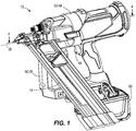
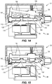
- FIGS. 1-6 illustrate a power tool, such as a gas spring-powered fastener driver 10, operable to drive fasteners (e.g., nails, tacks, staples, etc.) held within a magazine 14 into a workpiece.
- the fastener driver 10 is configured as a multi-shot powered nailer including a magazine 14 holding a collated strip of nails, allowing the user to perform multiple fastening operations without having to manually reload the fastener driver after each driving cycle.
- the fasteners can instead be embodied as staples, brads, etc.
- the fastener driver 10 can drive two different-length nails depending, for example, on the thickness of the workpiece to be fixed in place.
- the magazine 14 is capable of accommodating either short nails 16a ( FIG.
- the magazine 14 will be described below in the context of the gas spring-powered fastener driver 10, the magazine 14 can equally be applied to other types of fastener drivers (e.g., a combustion nailer, a gas-free nailer, a pneumatic nailer, etc.).
- fastener drivers e.g., a combustion nailer, a gas-free nailer, a pneumatic nailer, etc.
- the gas spring-powered fastener driver 10 includes a cylinder 18 and a moveable piston 22 positioned within the cylinder 18.
- the fastener driver 10 further includes a driver blade 26 that is attached to the piston 22 and moveable therewith.
- the fastener driver 10 does not require an external source of air pressure, but rather includes a storage chamber cylinder 30 of pressurized gas in fluid communication with the cylinder 18.
- the cylinder 18 and moveable piston 22 are positioned within the storage chamber cylinder 30.
- the driver 10 further includes a fill valve 34 coupled to the storage chamber cylinder 30. When connected with a source of compressed gas, the fill valve 34 permits the storage chamber cylinder 30 to be refilled with compressed gas if any prior leakage has occurred.
- the fill valve 34 may be configured as a Schrader valve, for example.
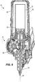
- the cylinder 18 and the driver blade 26 define a driving axis 38, and during a driving cycle the driver blade 26 and piston 22 are moveable between a ready position (i.e., top dead center; see FIG. 5 ) and a driven position (i.e., bottom dead center; see FIG. 6 ).
- the fastener driver 10 further includes a lifting assembly 42, which is powered by a motor 46 ( FIG. 4 ), and which is operable to move the driver blade 26 from the driven position to the ready position.
- the lifting assembly 42 drives the piston 22 and the driver blade 26 to the ready position by energizing the motor 46.
- the gas above the piston 22 and the gas within the storage chamber cylinder 30 is compressed.
- the piston 22 and the driver blade 26 are held in position until released by user activation of a trigger 48 ( FIG. 1 ).
- the compressed gas above the piston 22 and within the storage chamber 30 drives the piston 22 and the driver blade 26 to the driven position, thereby driving the nail 16a, 16b into a workpiece.
- the illustrated fastener driver 10 therefore operates on a gas spring principle utilizing the lifting assembly 42 and the piston 22 to further compress the gas within the cylinder 18 and the storage chamber cylinder 30. Further detail regarding the structure and operation of the fastener driver 10 is provided below.
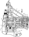
- the fastener driver 10 includes a housing 50 formed from clamshell housing halves.
- the housing 50 includes a cylinder support portion 54 ( FIG. 1 ) in which the storage chamber cylinder 30 is at least partially positioned, and a transmission housing portion 58 in which a transmission 62 is at least partially positioned.
- the transmission 62 is a component of the lifting assembly 42, which raises the driver blade 26 from the driven position to the ready position.
- the motor 46 is also a component of the lifting assembly 42 and is coupled to the transmission housing portion 58 for providing torque to the transmission 62 when activated.
- a battery 66 ( FIG. 1 ) is electrically connectable to the motor 46 for supplying electrical power to the motor 46.
- the driver may be powered from an AC voltage input (i.e., from a wall outlet), or by an alternative DC voltage input (e.g., a DC power support).
- the transmission 62 rotatably couples to a motor output shaft 74, and includes a transmission output shaft 78 extending to a lifter 82 of the lifting assembly 42 ( FIG. 3 ).
- the lifter 82 is operable to move the driver blade 26 from the driven position to the ready position.
- the transmission 62 provides torque to the lifter 82 from the motor 46.
- a fan 86 is rotatably coupled to the motor shaft 74 to generate cooling airflow within an interior of the fastener driver 10.
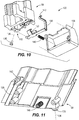
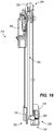
- the magazine 14 includes a shear block 90 at one end that is fastened to a nosepiece 94 ( FIG. 3 ) of the fastener driver 10 to secure the magazine 14 to the fastener driver 10.
- the magazine 14 also includes a loading portion 98 at the opposite end that receives the nails 16a, 16b for loading into the magazine 14.
- the nails 16a, 16b enter through the loading portion 98 and advance into a feed channel 102 ( FIG. 12 ) that extends within the magazine 14 from the loading portion 98 to the shear block 90.
- a pusher 106 is biased toward the shear block 90 and urges the loaded nails 16a, 16b toward the shear block 90.
- the feed channel 102 includes a long nail slot 110 and a short nail slot 114, each configured to receive a respective long nail 16b ( FIG. 13 ) or short nail 16a ( FIG. 14 ).
- a respective long nail 16b FIG. 13
- short nail 16a FIG. 14
- the short and long nails 16a, 16b will be loaded such that a tip portion 118 of either type is located in the same location relative to the driver blade 26 when the nail 16a or 16b is next to be fired.
- the loading portion 98 also includes a feed channel access gate 122 to prevent the short nails 16a from being improperly loaded into the long nail slot 110.
- the feed channel access gate 122 is configured as a pivot member 126 attached to the magazine 14 by a pin 130 and rotatable about a pivot axis 134 ( FIG. 10 ).
- the pivot member 126 swings about the pivot axis 134 within a space enclosed by a bracket 138, between a blocking position ( FIG. 12 ) and a bypass position ( FIG. 13 ).
- the pivot member 126 includes a blocking tab 142, and the pivot member 126 is biased by a spring 146 toward the blocking position ( FIG. 12 ) at which the blocking tab 142 occupies and obstructs a portion of the long nail slot 110.
- the pivot member 126 also includes a ramp 150 located adjacent a forward end 154 of the feed channel 102.
- the tip portion 118 of the long nails 16b engages the ramp 150, causing the pivot member 126 to pivot toward the bypass position at which the blocking tab 142 vacates the long nail slot 110 and the long nails 16b are thus permitted to enter the feed channel 102.
- the tip portion 118 of the short nails 16a engages the ramp 150, causing the pivot member 126 to pivot toward the bypass position such that the short nails 16a are permitted to enter the feed channel 102.
- FIG. 15 illustrates a scenario in which an attempt is made to improperly load the short nails 16a into the feed channel 102 via the long nail slot 110.
- the tip portion 118 of the short nails 16a do not reach sufficiently far to engage the ramp 150 of the pivot member 126.
- the pivot member 126 remains in the blocking position at which the blocking tab 142 obstructs the long nail slot 110, and the short nails 16a cannot enter the feed channel 102.
- the feed channel access gate 122 reduces the number of jams that otherwise may result during operation of the fastener driver 10.
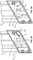
- FIGS. 16-28 illustrate another magazine 214 having a feed channel access gate 322 according to another embodiment of the invention.
- the magazine 214 is similar to the magazine 14 and includes substantially the same structure as the magazine 14. Accordingly, the following description focuses primarily on the structure and features that are different from the embodiments described above in connection with FIGS. 1-15 .
- Features and elements that are described in connection with FIGS. 1-15 are numbered in the 200 and 300 series of reference numerals in FIGS. 16-28 . It should be understood that features of the magazine 214 that are not explicitly described below have the same properties as the features of the magazine 14.
- the magazine 214 includes a shear block 290 at a first end 292 that is fastened to the nosepiece 94 ( FIG. 3 ) of the fastener driver 10 to secure the magazine 214 to the fastener driver 10.
- the magazine 214 also includes a loading portion 298 at an opposite second end 300 that receives the nails 16a, 16b for loading into the magazine 214.
- the nails 16a, 16b enter through the loading portion 298 and advance into a feed channel 302 ( FIG. 21 ) that extends within the magazine 214 from the loading portion 298 to the shear block 290.
- a pusher 306 ( FIG. 17 ) is biased toward the shear block 290 and urges the loaded nails 16a, 16b toward the shear block 290.
- the feed channel 302 includes a long nail slot 310 and a short nail slot 314, each configured to receive the respective long or short nails 16b, 16a ( FIGS. 13 and 14 ).
- the long and short nails 16b, 16a When properly loaded into a respective slot 310, 314, the long and short nails 16b, 16a will be loaded such that the tip portion 118 ( FIGS. 13 and 14 ) of either type is located in the same location relative to the driver blade 26 ( FIG. 6 ) when the nail 16a or 16b is next to be fired.
- the loading portion 298 also includes a feed channel access gate 322 to prevent the short nails 16a from being improperly loaded into the long nail slot 310.
- the feed channel access gate 322 is configured as a pivot member 326 attached to the magazine 214 by a pin 330 and rotatable about a pivot axis 334 ( FIG. 19 ).
- the pivot member 326 swings about the pivot axis 334 within a space enclosed by a bracket 338, between a blocking position ( FIG. 21 ) and a bypass position ( FIG. 22 ).
- the pivot member 326 includes a blocking tab 342, and the pivot member 326 is biased by a spring 346 toward the blocking position ( FIG. 21 ) at which the blocking tab 342 occupies and obstructs a portion of the long nail slot 310.
- the pivot member 326 also includes a ramp 350 located adjacent a forward end 354 of the feed channel 302.
- the feed channel access gate 322 operates in a manner similar to that described above with regard to FIGS. 13-14 .
- the tip portion 118 of the long nails 16b engages the ramp 350, causing the pivot member 326 to pivot toward the bypass position at which the blocking tab 342 vacates the long nail slot 310 and the long nails 16b are thus permitted to enter the feed channel 302.
- the tip portion 118 of the short nails 16a engages the ramp 350, causing the pivot member 326 to pivot toward the bypass position such that the short nails 16a are permitted to enter the feed channel 302.
- the tip portion 118 of the short nails 16a does not reach sufficiently far to engage the ramp 350 of the pivot member 326.
- the pivot member 326 remains in the blocking position at which the blocking tab 342 obstructs the long nail slot 310, and the short nails 16a cannot enter the feed channel 302.
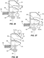
- FIGS. 23-28 illustrate the pivot member 326 in greater detail.
- the pivot member 326 may be manufactured from a blank sheet of material (e.g., metal) that is subjected to a stamping and forming process.
- the pivot member 326 is formed having a shape that is generally easier to manufacture than that of the pivot member 126 described above.
- the pivot member 326 includes a pair of parallel pivot arms 358 that each define a respective pivot aperture 362.
- Each pivot aperture 362 is centered about the pivot axis 334 and cooperates to receive the pin 330.
- the pivot arms 358 are separated from one another by a distance L ( FIG. 24 ), and each pivot aperture includes a diameter D ( FIG. 25 ).
- a ratio of the distance L to the diameter D is greater than 1.5 (i.e., L/D > 1.5).
- An L/D ratio greater than 1.5 generally prevents against binding or window locking as the pivot member 326 pivots about the pivot axis 334, thus providing better support and smoother operation.
- the blocking tab 342 includes an inclined portion 366 inclined generally toward the pivot axis 334 and toward the second end 300 ( FIG. 16 ) of the magazine 214.
- the nails 16a, 16b perceive an inclined angle ⁇ measured generally between the inclined portion 366 and the pivot arm 358.
- the inclined portion 366 causes the pivot member 326 to move further toward the blocking position ( FIG. 21 ) if the short nails 16a are inserted into the long nail slot 310.
- the inclined portion 366 further helps to prevent the blocking tab 342 from failing due to wear.
- the ramp 350 includes a first chamfer 370 inclined generally away from the pivot axis 334 and away from the second end 300 ( FIG. 16 ) of the magazine 214.
- the nails 16a, 16b perceive a first chamfer angle ⁇ measured generally between the first chamfer 370 and the pivot arm 358.
- the first chamfer 370 causes the pivot member 326 to move toward the bypass position ( FIG. 22 ) upon contact with the nails 16a, 16b.
- the first chamfer angle ⁇ allows a nail insertion force to be minimal but greater than 4.5N (one pound (i.e., 1 lbf)).
- the blocking tab 342 includes a second chamfer 374 that is inclined generally toward the pivot axis 334 and toward the second end 300 ( FIG. 16 ) of the magazine 214.
- the nails 16a, 16b perceive a second chamfer angle ⁇ measured generally between the second chamfer 374 and the pivot arm 358.
- the second chamfer 374 causes the pivot member 326 to move toward the bypass position ( FIG. 22 ) upon contact with the nails 16a, 16b.
- the second chamfer angle ⁇ is greater than the first chamfer angle ⁇ , thereby allowing the nails 16a, 16b to be removed from the magazine 214 with minimal force required.
- the pivot axis 334 is inclined relative to the feed direction indicated by the arrow in FIG. 29 .
- a pivot axis angle B is measured generally between the pivot axis 334 and the feed direction. In the illustrated embodiment, the pivot axis angle B measures approximately 30 degrees. In other embodiments, the pivot axis angle may measure more or less than 30 degrees (e.g., between 5 and 60 degrees), so that the pivot axis 334 is more or less inclined relative to the feed direction.
- the inclination of the pivot axis 334 causes the blocking tab 342 and the ramp 350 to move slightly downward (i.e., in a direction opposite the feed direction) as the blocking tab 342 and the ramp 30 vacate the feed channel 302.
- the downward motion of the blocking tab 342 and the ramp 350 can cause self-locking (i.e. jamming) of the pivot member 326 when the nails 16a, 16b are inserted into the magazine 214.
- the pivot axis 334 may be inclined in the opposite way, which can cause self-locking of the pivot member 326 when the nails 16a, 16b are removed from the magazine.
- FIG. 30 illustrates another magazine 214A having a feed channel access gate 322A according to another embodiment of the invention.
- the magazine 214A is similar to the magazine 214 and includes substantially the same structure as the magazine 214.
- the magazine 214A differs from the magazine 214 in that the magazine 214A includes a pivot member 326A rotatable about a pivot axis 334A oriented parallel to the feed direction indicated by the arrow in FIG. 30 . Because the pivot axis 334A is parallel to the feed direction, the blocking tab 342A and the ramp 350A move in and out of the magazine 214A (i.e., in and out of the page in FIG. 30 ) and do not have a downward (i.e., in a direction opposite the feed direction) component of motion. This prevents the pivot member 326A from self-locking when the nails 16a, 16b are inserted into the magazine 214A, or when the nails 16a, 16b are removed from the magazine 214A.
Landscapes
- Engineering & Computer Science (AREA)
- Mechanical Engineering (AREA)
- Portable Nailing Machines And Staplers (AREA)
Claims (15)
- Angetriebenes Befestigungselement-Eintreibgerät (10), das Folgendes umfasst:ein Magazin (14, 214, 214A), in dem Befestigungselemente einer ersten Länge (16a) oder Befestigungselemente einer zweiten Länge (16b), die größer ist als die erste Länge, aufgenommen werden können, wobei das Magazin Folgendes einschließt:einen Scherblock (90, 290), der an einem ersten Ende des Magazins angeordnet ist,einen Ladeabschnitt (98, 298), der an einem zweiten Ende des Magazins, entgegengesetzt zu dem ersten Ende, angeordnet ist, undeinen Zufuhrkanal (102, 302), der sich zwischen dem Scherblock und dem Ladeabschnitt in Längsrichtung durch das Magazin erstreckt,wobei der Ladeabschnitt des Magazins einen ersten Schlitz (114, 314) und einen zweiten Schlitz (110, 310), die jeweils dafür konfiguriert sind, Befestigungselemente der entsprechenden ersten und zweiten Länge zum Eintritt in den Zufuhrkanal aufzunehmen, und eine Zufuhrkanal-Zugangspforte (122, 322, 322A), die dafür konfiguriert ist, zu verhindern, dass Befestigungselemente der ersten Länge in den zweiten Schlitz geladen werden, einschließt,dadurch gekennzeichnet, dassdie Zufuhrkanal-Zugangspforte als ein Schwenkelement (126, 326, 326A) konfiguriert ist, das um eine Schwenkachse (134, 334, 334A) schwenkbar ist zwischen einer ersten Sperrstellung, die einen Zugang zu dem zweiten Schlitz sperrt, und einer zweiten Umgehungsstellung, die einen Zugang zu dem zweiten Schlitz erlaubt, undwobei das angetriebene Befestigungselement-Eintreibgerät ferner eine Feder (146, 246) umfasst und wobei die Feder das Schwenkelement hin zu der Sperrstellung vorspannt.
- Angetriebenes Befestigungselement-Eintreibgerät nach Anspruch 1, wobei das Schwenkelement eine Sperrlasche (142, 342) einschließt, die dafür konfiguriert ist, einen Abschnitt des zweiten Schlitzes zu versperren, wenn sich das Schwenkelement in der Sperrstellung befindet.
- Angetriebenes Befestigungselement-Eintreibgerät nach Anspruch 2, wobei die Sperrlasche einen geneigten Abschnitt (366) einschließt, der hin zu dem zweiten Ende des Magazins geneigt und dafür konfiguriert ist, das Schwenkelement weiter hin zu der Sperrstellung zu bewegen, wenn ein Befestigungselement der ersten Länge in den zweiten Schlitz geladen wird.
- Angetriebenes Befestigungselement-Eintreibgerät nach Anspruch 2 oder 3, wobei das Schwenkelement eine Rampe (150, 350, 350A) einschließt, die dafür konfiguriert ist, eine Spitze (118) der Befestigungselemente der ersten Länge oder eine Spitze (118) der Befestigungselemente der zweiten Länge in Eingriff zu nehmen.
- Angetriebenes Befestigungselement-Eintreibgerät nach Anspruch 4, wobei, wenn ein Befestigungselement der ersten Länge in den ersten Schlitz geladen wird, die Spitze des Befestigungselements der ersten Länge die Rampe in Eingriff nimmt und das Schwenkelement zu der Umgehungsstellung bewegt.
- Angetriebenes Befestigungselement-Eintreibgerät nach Anspruch 4 oder 5, wobei, wenn ein Befestigungselement der zweiten Länge in den zweiten Schlitz geladen wird, die Spitze des Befestigungselements der zweiten Länge die Rampe in Eingriff nimmt und das Schwenkelement zu der Umgehungsstellung bewegt.
- Angetriebenes Befestigungselement-Eintreibgerät nach Anspruch 4, wobei, wenn ein Befestigungselement der ersten Länge in den zweiten Schlitz geladen wird, die Spitze des Befestigungselements der ersten Länge die Rampe nicht in Eingriff nimmt und das Schwenkelement in der Sperrstellung verbleibt.
- Angetriebenes Befestigungselement-Eintreibgerät nach einem der Ansprüche 4 bis 7, wobei die Rampe eine erste Abschrägung (370) einschließt, die um einen ersten Abschrägungswinkel (α) weg von dem zweiten Ende des Magazins geneigt ist.
- Angetriebenes Befestigungselement-Eintreibgerät nach Anspruch 8, wobei die Sperrlasche eine zweite Abschrägung (374) einschließt, die um einen zweiten Abschrägungswinkel (β), der größer ist als der erste Abschrägungswinkel, hin zu dem zweiten Ende des Magazins geneigt ist, und
wobei die zweite Abschrägung dafür konfiguriert ist, durch Eingriff mit der Spitze eines der Befestigungselemente der ersten Länge und der Befestigungselemente der zweiten Länge das Schwenkelement zu der Umgehungsstellung zu bewegen. - Angetriebenes Befestigungselement-Eintreibgerät nach einem der vorhergehenden Ansprüche, wobei:(i) das Schwenkelement durch einen Zapfen (130, 330), der die Schwenkachse definiert, an das Magazin gekoppelt ist,
und/oder(ii) das Schwenkelement ein Paar von parallelen Schwenkarmen (358) einschließt, die um eine Entfernung (L) voneinander beabstandet sind, wobei jeder Schwenkarm eine Schwenköffnung (362) mit einem Durchmesser (D) einschließt, wobei ein Verhältnis der Entfernung zu dem Durchmesser größer als 1,5 ist,
und/oder(iii) der Zufuhrkanal eine Zufuhrrichtung definiert, entlang derer die Befestigungselemente der ersten und der zweiten Länge in das Magazin eingesetzt werden, und die Schwenkachse parallel zu der Zufuhrrichtung ist,
und/oder(iv) der Zufuhrkanal eine Zufuhrrichtung definiert, entlang derer die Befestigungselemente der ersten und der zweiten Länge in das Magazin eingesetzt werden, und die Schwenkachse in Bezug auf die Zufuhrrichtung um einen Schwenkachsenwinkel (B) von zwischen 5 Grad und 60 Grad geneigt ist. - Angetriebenes Befestigungselement-Eintreibgerät nach Anspruch 1, wobei:die Schwenkachse parallel zu der Zufuhrrichtung ist.
- Angetriebenes Befestigungselement-Eintreibgerät nach Anspruch 11, wobei das Magazin einen Drücker (106, 306) einschließt, der hin zu dem Scherblock vorgespannt wird, und wobei, wenn die Befestigungselemente der ersten Länge oder die Befestigungselemente der zweiten Länge in dem Magazin aufgenommen werden, der Drücker dafür konfiguriert ist, die Befestigungselemente hin zu dem Scherblock zu drängen.
- Angetriebenes Befestigungselement-Eintreibgerät nach Anspruch 11 oder 12, wobei das Schwenkelement durch einen Zapfen (130, 330), der die Schwenkachse definiert, an das Magazin gekoppelt ist.
- Angetriebenes Befestigungselement-Eintreibgerät nach einem der Ansprüche 11 bis 13, wobei das Schwenkelement dafür konfiguriert ist, aus einer unbearbeiteten Materialbahn gefertigt zu werden, die einem Stanz- und Formvorgang unterworfen wird.
- Angetriebenes Befestigungselement-Eintreibgerät nach einem der Ansprüche 11 bis 14, wobei das Schwenkelement eine Sperrlasche (142, 342) einschließt, die einen Abschnitt des zweiten Schlitzes versperrt, wenn sich das Schwenkelement in der Sperrstellung befindet, wobei die Sperrlasche einen geneigten Abschnitt (366) und eine Abschrägung, die auf entgegengesetzten Seiten derselben angeordnet sind, einschließt, wobei der geneigte Abschnitt mit den Befestigungselementen der ersten Länge in Eingriff gebracht werden kann, um das Schwenkelement weiter hin zu der Sperrstellung zu bewegen, wenn die Befestigungselemente der ersten Länge in den zweiten Schlitz eingesetzt werden, die Abschrägung mit den Befestigungselementen der ersten Länge in Eingriff gebracht werden kann, um das Schwenkelement hin zu der Umgehungsstellung zu bewegen, wenn die Befestigungselemente der ersten Länge aus dem ersten Schlitz entfernt werden, und die Abschrägung mit den Befestigungselementen der zweiten Länge in Eingriff gebracht werden kann, um das Schwenkelement hin zu der Umgehungsstellung zu bewegen, wenn die Befestigungselemente der zweiten Länge aus dem zweiten Schlitz entfernt werden,
und, wahlweise,
wobei das Schwenkelement eine Rampe (150, 350, 350A) einschließt, die dafür konfiguriert ist, eine Spitze (118) der Befestigungselemente der ersten Länge oder eine Spitze (118) der Befestigungselemente der zweiten Länge in Eingriff zu nehmen,
und, wahlweise,
wobei, wenn ein Befestigungselement der ersten Länge in den ersten Schlitz eingesetzt wird, die Spitze des Befestigungselements der ersten Länge die Rampe in Eingriff nimmt und das Schwenkelement zu der Umgehungsstellung bewegt, und
wobei, wenn ein Befestigungselement der zweiten Länge in den zweiten Schlitz eingesetzt wird, die Spitze des Befestigungselements der zweiten Länge die Rampe in Eingriff nimmt und das Schwenkelement zu der Umgehungsstellung bewegt.
Applications Claiming Priority (2)
| Application Number | Priority Date | Filing Date | Title |
|---|---|---|---|
| US201962817650P | 2019-03-13 | 2019-03-13 | |
| US201962834998P | 2019-04-17 | 2019-04-17 |
Publications (2)
| Publication Number | Publication Date |
|---|---|
| EP3725465A1 EP3725465A1 (de) | 2020-10-21 |
| EP3725465B1 true EP3725465B1 (de) | 2021-12-08 |
Family
ID=69804518
Family Applications (1)
| Application Number | Title | Priority Date | Filing Date |
|---|---|---|---|
| EP20162176.0A Active EP3725465B1 (de) | 2019-03-13 | 2020-03-10 | Angetriebener befestigungsmitteltreiber |
Country Status (3)
| Country | Link |
|---|---|
| US (2) | US11433521B2 (de) |
| EP (1) | EP3725465B1 (de) |
| CN (1) | CN212240860U (de) |
Families Citing this family (4)
| Publication number | Priority date | Publication date | Assignee | Title |
|---|---|---|---|---|
| CN219255473U (zh) | 2020-03-25 | 2023-06-27 | 米沃奇电动工具公司 | 紧固件驱动器 |
| EP4537985A3 (de) * | 2022-02-21 | 2025-07-30 | Kyocera Senco Industrial Tools, Inc. | Magazinhalterführung für ein werkzeug zum eintreiben von befestigungsmitteln |
| US20230356376A1 (en) * | 2022-05-03 | 2023-11-09 | Milwaukee Electric Tool Corporation | One-piece fill valve for powered fastener driver |
| US20250229395A1 (en) * | 2024-01-12 | 2025-07-17 | Milwaukee Electric Tool Corporation | Powered fastener driver |
Family Cites Families (26)
| Publication number | Priority date | Publication date | Assignee | Title |
|---|---|---|---|---|
| DE8901289U1 (de) | 1989-01-14 | 1989-06-08 | Paslode GmbH, 6236 Eschborn | Nageleintreibgerät |
| US5803338A (en) * | 1996-11-26 | 1998-09-08 | Senco Products, Inc. | Fastener driving tool for locating a pre-existing hole in a first workpiece and driving a fastener therethrough into a second workpiece |
| US6053389A (en) | 1998-08-05 | 2000-04-25 | Sup Drogon Enterprise Co., Ltd. | Nailing gun magazine specially designed for big nail set |
| US6592016B2 (en) | 2000-01-13 | 2003-07-15 | Max Co., Ltd. | Nailing machine |
| JP2001198846A (ja) | 2000-01-13 | 2001-07-24 | Max Co Ltd | 釘打機のノーズ部内における釘の案内構造 |
| DE60122091T2 (de) | 2000-11-16 | 2007-03-08 | Max Co. Ltd. | Zuführvorrichtung von Nagelstreifen für Nagelmaschinen |
| JP3757786B2 (ja) * | 2000-11-17 | 2006-03-22 | 日立工機株式会社 | 釘打機のマガジン装置 |
| US6808101B2 (en) | 2002-05-24 | 2004-10-26 | Illinois Tool Works Inc. | Framing tool with automatic fastener-size adjustment |
| US6679414B2 (en) | 2002-06-13 | 2004-01-20 | Illinois Tool Works Inc. | Interchangeable magazine for a tool |
| US6739490B1 (en) | 2002-06-24 | 2004-05-25 | Illinois Tool Works Inc. | Fastener supply and positioning mechanism for a tool |
| US7143508B2 (en) | 2002-09-18 | 2006-12-05 | Black & Decker Inc. | Nail spacing verification assembly |
| US7025242B1 (en) | 2002-09-18 | 2006-04-11 | Black & Decker Inc. | Adjustable angle magazine |
| JP4348995B2 (ja) | 2003-05-08 | 2009-10-21 | マックス株式会社 | 釘打機における釘の打出し案内機構 |
| US6908021B1 (en) * | 2004-02-04 | 2005-06-21 | Nailermate Enterprise Corp. | Safety catch mechanism of nail guns |
| JP4618537B2 (ja) | 2004-07-15 | 2011-01-26 | 日立工機株式会社 | 釘打機 |
| TWI286966B (en) * | 2006-01-17 | 2007-09-21 | Basso Ind Corp | Structure against malposition for nail case |
| US20080067212A1 (en) * | 2006-09-14 | 2008-03-20 | Wan-Fu Wen | Magazine for Nail Gun |
| EP2083969B1 (de) | 2006-10-20 | 2013-01-02 | Stanely Fastening Systems, L.P. | Eintreibgerät mit mechanismen zur begrenzung der nagelbewegung |
| US8931676B2 (en) | 2007-08-27 | 2015-01-13 | Black & Decker Inc. | Nailer having mechanism for pre-positioning nail |
| FR2920332B1 (fr) | 2007-09-05 | 2010-04-23 | Spit Soc Prospect Inv Techn | Outil de fixation pour la fixation d'elements de differentes longueurs |
| JP5701658B2 (ja) * | 2011-03-31 | 2015-04-15 | 株式会社マキタ | 打ち込み工具 |
| ITBO20110303A1 (it) * | 2011-05-25 | 2012-11-26 | Fasco Srl | Dispositivo a caricatore per chiodatrice e simili |
| US20130320062A1 (en) * | 2012-06-04 | 2013-12-05 | Illinois Tool Works Inc. | Dual channel magazine lockout system |
| TWM463638U (zh) | 2013-06-05 | 2013-10-21 | Basso Ind Corp | 防止釘排錯位的釘匣裝置 |
| US9527196B2 (en) | 2013-11-06 | 2016-12-27 | Illinois Tool Works Inc. | Fastener driving tool with an automatic nose chamber guide member |
| EP3398719A1 (de) | 2017-05-05 | 2018-11-07 | Illinois Tool Works Inc. | Magazin eines fixierungswerkzeugs |
-
2020
- 2020-02-26 US US16/801,711 patent/US11433521B2/en active Active
- 2020-03-10 EP EP20162176.0A patent/EP3725465B1/de active Active
- 2020-03-13 CN CN202020318792.8U patent/CN212240860U/zh active Active
-
2022
- 2022-09-01 US US17/901,238 patent/US20220410357A1/en not_active Abandoned
Also Published As
| Publication number | Publication date |
|---|---|
| US20200290189A1 (en) | 2020-09-17 |
| US20220410357A1 (en) | 2022-12-29 |
| US11433521B2 (en) | 2022-09-06 |
| EP3725465A1 (de) | 2020-10-21 |
| CN212240860U (zh) | 2020-12-29 |
Similar Documents
| Publication | Publication Date | Title |
|---|---|---|
| US20220410357A1 (en) | Powered fastener driver | |
| EP4153382B1 (de) | Trockenfeuersperre und letzte befestigungselementrückhaltevorrichtung für angetriebenen befestigungselementtreiber | |
| US7757920B2 (en) | Combustion nailer workpiece contact element with enhanced gripping | |
| US20230150101A1 (en) | Powered fastener driver | |
| US12172275B2 (en) | Fastener driving tool | |
| US7025242B1 (en) | Adjustable angle magazine | |
| US20060231582A1 (en) | Stapler | |
| US20060102683A1 (en) | Adjustable angle magazine with pick-off pivot assembly | |
| US6986448B2 (en) | Fastener driving tool for spacing object from substrate | |
| US5711471A (en) | Magnetic biased driving element for a fastener driving tool | |
| US8757464B2 (en) | Powered stapling device | |
| US20060108390A1 (en) | Articulating pusher assembly | |
| US20250262735A1 (en) | Powered fastener driver | |
| US20250229395A1 (en) | Powered fastener driver | |
| US20240391075A1 (en) | Duplex nailer, magazine, and duplex nail for the same | |
| US7143508B2 (en) | Nail spacing verification assembly | |
| US20250375865A1 (en) | Fastening tool having position biased released valve | |
| US8844785B2 (en) | Powered stapler and method of operating same | |
| JPH0121732Y2 (de) | ||
| WO2004085119A2 (en) | Power tool for metal piercing fasteners |
Legal Events
| Date | Code | Title | Description |
|---|---|---|---|
| PUAI | Public reference made under article 153(3) epc to a published international application that has entered the european phase |
Free format text: ORIGINAL CODE: 0009012 |
|
| STAA | Information on the status of an ep patent application or granted ep patent |
Free format text: STATUS: REQUEST FOR EXAMINATION WAS MADE |
|
| 17P | Request for examination filed |
Effective date: 20200310 |
|
| AK | Designated contracting states |
Kind code of ref document: A1 Designated state(s): AL AT BE BG CH CY CZ DE DK EE ES FI FR GB GR HR HU IE IS IT LI LT LU LV MC MK MT NL NO PL PT RO RS SE SI SK SM TR |
|
| AX | Request for extension of the european patent |
Extension state: BA ME |
|
| GRAP | Despatch of communication of intention to grant a patent |
Free format text: ORIGINAL CODE: EPIDOSNIGR1 |
|
| STAA | Information on the status of an ep patent application or granted ep patent |
Free format text: STATUS: GRANT OF PATENT IS INTENDED |
|
| INTG | Intention to grant announced |
Effective date: 20210706 |
|
| GRAS | Grant fee paid |
Free format text: ORIGINAL CODE: EPIDOSNIGR3 |
|
| GRAA | (expected) grant |
Free format text: ORIGINAL CODE: 0009210 |
|
| STAA | Information on the status of an ep patent application or granted ep patent |
Free format text: STATUS: THE PATENT HAS BEEN GRANTED |
|
| AK | Designated contracting states |
Kind code of ref document: B1 Designated state(s): AL AT BE BG CH CY CZ DE DK EE ES FI FR GB GR HR HU IE IS IT LI LT LU LV MC MK MT NL NO PL PT RO RS SE SI SK SM TR |
|
| REG | Reference to a national code |
Ref country code: GB Ref legal event code: FG4D |
|
| REG | Reference to a national code |
Ref country code: AT Ref legal event code: REF Ref document number: 1453400 Country of ref document: AT Kind code of ref document: T Effective date: 20211215 Ref country code: CH Ref legal event code: EP |
|
| REG | Reference to a national code |
Ref country code: DE Ref legal event code: R096 Ref document number: 602020001194 Country of ref document: DE |
|
| REG | Reference to a national code |
Ref country code: IE Ref legal event code: FG4D |
|
| REG | Reference to a national code |
Ref country code: LT Ref legal event code: MG9D |
|
| REG | Reference to a national code |
Ref country code: NL Ref legal event code: MP Effective date: 20211208 |
|
| PG25 | Lapsed in a contracting state [announced via postgrant information from national office to epo] |
Ref country code: RS Free format text: LAPSE BECAUSE OF FAILURE TO SUBMIT A TRANSLATION OF THE DESCRIPTION OR TO PAY THE FEE WITHIN THE PRESCRIBED TIME-LIMIT Effective date: 20211208 Ref country code: LT Free format text: LAPSE BECAUSE OF FAILURE TO SUBMIT A TRANSLATION OF THE DESCRIPTION OR TO PAY THE FEE WITHIN THE PRESCRIBED TIME-LIMIT Effective date: 20211208 Ref country code: FI Free format text: LAPSE BECAUSE OF FAILURE TO SUBMIT A TRANSLATION OF THE DESCRIPTION OR TO PAY THE FEE WITHIN THE PRESCRIBED TIME-LIMIT Effective date: 20211208 Ref country code: BG Free format text: LAPSE BECAUSE OF FAILURE TO SUBMIT A TRANSLATION OF THE DESCRIPTION OR TO PAY THE FEE WITHIN THE PRESCRIBED TIME-LIMIT Effective date: 20220308 |
|
| REG | Reference to a national code |
Ref country code: AT Ref legal event code: MK05 Ref document number: 1453400 Country of ref document: AT Kind code of ref document: T Effective date: 20211208 |
|
| PG25 | Lapsed in a contracting state [announced via postgrant information from national office to epo] |
Ref country code: SE Free format text: LAPSE BECAUSE OF FAILURE TO SUBMIT A TRANSLATION OF THE DESCRIPTION OR TO PAY THE FEE WITHIN THE PRESCRIBED TIME-LIMIT Effective date: 20211208 Ref country code: NO Free format text: LAPSE BECAUSE OF FAILURE TO SUBMIT A TRANSLATION OF THE DESCRIPTION OR TO PAY THE FEE WITHIN THE PRESCRIBED TIME-LIMIT Effective date: 20220308 Ref country code: LV Free format text: LAPSE BECAUSE OF FAILURE TO SUBMIT A TRANSLATION OF THE DESCRIPTION OR TO PAY THE FEE WITHIN THE PRESCRIBED TIME-LIMIT Effective date: 20211208 Ref country code: HR Free format text: LAPSE BECAUSE OF FAILURE TO SUBMIT A TRANSLATION OF THE DESCRIPTION OR TO PAY THE FEE WITHIN THE PRESCRIBED TIME-LIMIT Effective date: 20211208 Ref country code: GR Free format text: LAPSE BECAUSE OF FAILURE TO SUBMIT A TRANSLATION OF THE DESCRIPTION OR TO PAY THE FEE WITHIN THE PRESCRIBED TIME-LIMIT Effective date: 20220309 |
|
| PG25 | Lapsed in a contracting state [announced via postgrant information from national office to epo] |
Ref country code: NL Free format text: LAPSE BECAUSE OF FAILURE TO SUBMIT A TRANSLATION OF THE DESCRIPTION OR TO PAY THE FEE WITHIN THE PRESCRIBED TIME-LIMIT Effective date: 20211208 |
|
| PG25 | Lapsed in a contracting state [announced via postgrant information from national office to epo] |
Ref country code: SM Free format text: LAPSE BECAUSE OF FAILURE TO SUBMIT A TRANSLATION OF THE DESCRIPTION OR TO PAY THE FEE WITHIN THE PRESCRIBED TIME-LIMIT Effective date: 20211208 Ref country code: SK Free format text: LAPSE BECAUSE OF FAILURE TO SUBMIT A TRANSLATION OF THE DESCRIPTION OR TO PAY THE FEE WITHIN THE PRESCRIBED TIME-LIMIT Effective date: 20211208 Ref country code: RO Free format text: LAPSE BECAUSE OF FAILURE TO SUBMIT A TRANSLATION OF THE DESCRIPTION OR TO PAY THE FEE WITHIN THE PRESCRIBED TIME-LIMIT Effective date: 20211208 Ref country code: PT Free format text: LAPSE BECAUSE OF FAILURE TO SUBMIT A TRANSLATION OF THE DESCRIPTION OR TO PAY THE FEE WITHIN THE PRESCRIBED TIME-LIMIT Effective date: 20220408 Ref country code: ES Free format text: LAPSE BECAUSE OF FAILURE TO SUBMIT A TRANSLATION OF THE DESCRIPTION OR TO PAY THE FEE WITHIN THE PRESCRIBED TIME-LIMIT Effective date: 20211208 Ref country code: EE Free format text: LAPSE BECAUSE OF FAILURE TO SUBMIT A TRANSLATION OF THE DESCRIPTION OR TO PAY THE FEE WITHIN THE PRESCRIBED TIME-LIMIT Effective date: 20211208 Ref country code: CZ Free format text: LAPSE BECAUSE OF FAILURE TO SUBMIT A TRANSLATION OF THE DESCRIPTION OR TO PAY THE FEE WITHIN THE PRESCRIBED TIME-LIMIT Effective date: 20211208 |
|
| PG25 | Lapsed in a contracting state [announced via postgrant information from national office to epo] |
Ref country code: PL Free format text: LAPSE BECAUSE OF FAILURE TO SUBMIT A TRANSLATION OF THE DESCRIPTION OR TO PAY THE FEE WITHIN THE PRESCRIBED TIME-LIMIT Effective date: 20211208 Ref country code: AT Free format text: LAPSE BECAUSE OF FAILURE TO SUBMIT A TRANSLATION OF THE DESCRIPTION OR TO PAY THE FEE WITHIN THE PRESCRIBED TIME-LIMIT Effective date: 20211208 |
|
| REG | Reference to a national code |
Ref country code: DE Ref legal event code: R097 Ref document number: 602020001194 Country of ref document: DE |
|
| PG25 | Lapsed in a contracting state [announced via postgrant information from national office to epo] |
Ref country code: IS Free format text: LAPSE BECAUSE OF FAILURE TO SUBMIT A TRANSLATION OF THE DESCRIPTION OR TO PAY THE FEE WITHIN THE PRESCRIBED TIME-LIMIT Effective date: 20220408 |
|
| PLBE | No opposition filed within time limit |
Free format text: ORIGINAL CODE: 0009261 |
|
| STAA | Information on the status of an ep patent application or granted ep patent |
Free format text: STATUS: NO OPPOSITION FILED WITHIN TIME LIMIT |
|
| PG25 | Lapsed in a contracting state [announced via postgrant information from national office to epo] |
Ref country code: MC Free format text: LAPSE BECAUSE OF FAILURE TO SUBMIT A TRANSLATION OF THE DESCRIPTION OR TO PAY THE FEE WITHIN THE PRESCRIBED TIME-LIMIT Effective date: 20211208 Ref country code: DK Free format text: LAPSE BECAUSE OF FAILURE TO SUBMIT A TRANSLATION OF THE DESCRIPTION OR TO PAY THE FEE WITHIN THE PRESCRIBED TIME-LIMIT Effective date: 20211208 Ref country code: AL Free format text: LAPSE BECAUSE OF FAILURE TO SUBMIT A TRANSLATION OF THE DESCRIPTION OR TO PAY THE FEE WITHIN THE PRESCRIBED TIME-LIMIT Effective date: 20211208 |
|
| 26N | No opposition filed |
Effective date: 20220909 |
|
| PG25 | Lapsed in a contracting state [announced via postgrant information from national office to epo] |
Ref country code: SI Free format text: LAPSE BECAUSE OF FAILURE TO SUBMIT A TRANSLATION OF THE DESCRIPTION OR TO PAY THE FEE WITHIN THE PRESCRIBED TIME-LIMIT Effective date: 20211208 |
|
| REG | Reference to a national code |
Ref country code: BE Ref legal event code: MM Effective date: 20220331 |
|
| PG25 | Lapsed in a contracting state [announced via postgrant information from national office to epo] |
Ref country code: LU Free format text: LAPSE BECAUSE OF NON-PAYMENT OF DUE FEES Effective date: 20220310 Ref country code: IE Free format text: LAPSE BECAUSE OF NON-PAYMENT OF DUE FEES Effective date: 20220310 Ref country code: FR Free format text: LAPSE BECAUSE OF NON-PAYMENT OF DUE FEES Effective date: 20220331 |
|
| PG25 | Lapsed in a contracting state [announced via postgrant information from national office to epo] |
Ref country code: BE Free format text: LAPSE BECAUSE OF NON-PAYMENT OF DUE FEES Effective date: 20220331 |
|
| PG25 | Lapsed in a contracting state [announced via postgrant information from national office to epo] |
Ref country code: IT Free format text: LAPSE BECAUSE OF FAILURE TO SUBMIT A TRANSLATION OF THE DESCRIPTION OR TO PAY THE FEE WITHIN THE PRESCRIBED TIME-LIMIT Effective date: 20211208 |
|
| REG | Reference to a national code |
Ref country code: CH Ref legal event code: PL |
|
| PG25 | Lapsed in a contracting state [announced via postgrant information from national office to epo] |
Ref country code: LI Free format text: LAPSE BECAUSE OF NON-PAYMENT OF DUE FEES Effective date: 20230331 Ref country code: CH Free format text: LAPSE BECAUSE OF NON-PAYMENT OF DUE FEES Effective date: 20230331 |
|
| PG25 | Lapsed in a contracting state [announced via postgrant information from national office to epo] |
Ref country code: MK Free format text: LAPSE BECAUSE OF FAILURE TO SUBMIT A TRANSLATION OF THE DESCRIPTION OR TO PAY THE FEE WITHIN THE PRESCRIBED TIME-LIMIT Effective date: 20211208 Ref country code: CY Free format text: LAPSE BECAUSE OF FAILURE TO SUBMIT A TRANSLATION OF THE DESCRIPTION OR TO PAY THE FEE WITHIN THE PRESCRIBED TIME-LIMIT Effective date: 20211208 |
|
| PG25 | Lapsed in a contracting state [announced via postgrant information from national office to epo] |
Ref country code: HU Free format text: LAPSE BECAUSE OF FAILURE TO SUBMIT A TRANSLATION OF THE DESCRIPTION OR TO PAY THE FEE WITHIN THE PRESCRIBED TIME-LIMIT; INVALID AB INITIO Effective date: 20200310 |
|
| PG25 | Lapsed in a contracting state [announced via postgrant information from national office to epo] |
Ref country code: TR Free format text: LAPSE BECAUSE OF FAILURE TO SUBMIT A TRANSLATION OF THE DESCRIPTION OR TO PAY THE FEE WITHIN THE PRESCRIBED TIME-LIMIT Effective date: 20211208 |
|
| PG25 | Lapsed in a contracting state [announced via postgrant information from national office to epo] |
Ref country code: MT Free format text: LAPSE BECAUSE OF FAILURE TO SUBMIT A TRANSLATION OF THE DESCRIPTION OR TO PAY THE FEE WITHIN THE PRESCRIBED TIME-LIMIT Effective date: 20211208 |
|
| PGFP | Annual fee paid to national office [announced via postgrant information from national office to epo] |
Ref country code: DE Payment date: 20250327 Year of fee payment: 6 |
|
| PGFP | Annual fee paid to national office [announced via postgrant information from national office to epo] |
Ref country code: GB Payment date: 20250327 Year of fee payment: 6 |